

Page 1

Upgrading Routers from
Version 5 to Version 10.0
Router Software Version 10.0
Site Manager Software Version 4.0
Part No. 112938 Rev. A
February 1996
Page 2

4401 Great America Parkway 8 Federal Street
Santa Clara, CA 95054 Billerica, MA 01821
Copyright © 1988–1996 Bay Networks, Inc.
All rights reserved. Printed in the USA. February 1996.
The information in this document is subject to change without notice. The statements, configurations, technical data, and
recommendations in this document are believed to be accurate and reliable, but are presented without express or implied
warranty. Users must take full responsibility for their applications of any products specified in this document. The
information in this document is proprietary to Bay Networks, Inc.
The software described in this document is furnished under a license agreement and may only be used in accordance with the
terms of that license. A summary of the Software License is included in this document.
Restricted Rights Legend
Use, duplication, or disclosure by the United States Government is subject to restrictions as set forth in subparagraph
(c)(1)(ii) of the Rights in Technical Data and Computer Software clause at DFARS 252.227-7013.
Notice for All Other Executive Agencies
Notwithstanding any other license agreement that may pertain to, or accompany the delivery of, this computer software, the
rights of the United States Government regarding its use, reproduction, and disclosure are as set forth in the Commercial
Computer Software-Restricted Rights clause at FAR 52.227-19.
Trademarks of Bay Networks, Inc.
ACE, AFN, BCN, BLN, BN, CN, FRE, LN, Optivity, SynOptics, SynOptics Communications, Wellfleet and the Wellfleet
logo are registered trademarks and AN, ANH, ASN, BaySIS, BayStack, BCNX, BLNX, BNX, EZ Internetwork, EZ LAN,
FN, PathMan, PhonePlus, PPX, Quick2Config, RouterMan, SPEX, Bay Networks, Bay Networks Press, the Bay Networks
logo and the SynOptics logo are trademarks of Bay Networks, Inc.
Third-Party T rademarks
All other trademarks and registered trademarks are the property of their respective owners.
Statement of Conditions
In the interest of improving internal design, operational function, and/or reliability, Bay Networks, Inc. reserves the right to
make changes to the products described in this document without notice.
Bay Networks, Inc. does not assume any liability that may occur due to the use or application of the product(s) or circuit
layout(s) described herein.
Portions of the code in this software product are Copyright © 1988, Regents of the University of California. All rights
reserved. Redistribution and use in source and binary forms of such portions are permitted, provided that the above copyright
notice and this paragraph are duplicated in all such forms and that any documentation, advertising materials, and other
materials related to such distribution and use acknowledge that such portions of the software were developed by the
University of California, Berkeley. The name of the University may not be used to endorse or promote products deri ved from
such portions of the software without specific prior written permission.
SUCH PORTIONS OF THE SOFTWARE ARE PROVIDED “AS IS” AND WITHOUT ANY EXPRESS OR IMPLIED
WARRANTIES, INCLUDING, WITHOUT LIMITATION, THE IMPLIED WARRANTIES OF MERCHANTABILITY
AND FITNESS FOR A PARTICULAR PURPOSE.
In addition, the program and information contained herein are licensed only pursuant to a license agreement that contains
restrictions on use and disclosure (that may incorporate by reference certain limitations and notices imposed by third parties).
Page 3

Bay Networks Software License
Note:
This is Bay Networks basic license document. In the absence of a
software license agreement specifying varying terms, this license — or the
license included with the particular product — shall govern licensee’s use of
Bay Networks software.
This Software License shall govern the licensing of all software provided to licensee by Bay Networks (“Software”).
Bay Networks will provide licensee with Software in machine-readable form and related documentation
(“Documentation”). The Software provided under this license is proprietary to Bay Networks and to third parties from
whom Bay Networks has acquired license rights. Bay Networks will not grant any Software license whatsoev er , either
explicitly or implicitly, except by acceptance of an order for either Software or for a Bay Networks product
(“Equipment”) that is packaged with Software. Each such license is subject to the following restrictions:
1. Upon delivery of the Software, Bay Networks grants to licensee a personal, nontransferable, none xclusiv e license
to use the Software with the Equipment with which or for which it was originally acquired, including use at any
of licensee’s facilities to which the Equipment may be transferred, for the useful life of the Equipment unless
earlier terminated by default or cancellation. Use of the Software shall be limited to such Equipment and to such
facility. Software which is licensed for use on hardware not offered by Bay Networks is not subject to restricted
use on any Equipment, however, unless otherwise specified on the Documentation, each licensed copy of such
Software may only be installed on one hardware item at any time.
2. Licensee may use the Software with backup Equipment only if the Equipment with which or for which it was
acquired is inoperative.
3. Licensee may make a single copy of the Software (but not firmware) for safekeeping (archives) or backup
purposes.
4. Licensee may modify Software (but not firmware), or combine it with other software, subject to the provision
that those portions of the resulting software which incorporate Software are subject to the restrictions of this
license. Licensee shall not make the resulting software available for use by any third party.
5. Neither title nor ownership to Software passes to licensee.
6. Licensee shall not provide, or otherwise make available, any Software, in whole or in part, in any form, to any
third party. Third parties do not include consultants, subcontractors, or agents of licensee who have licensee’s
permission to use the Software at licensee’s facility, and who have agreed in writing to use the Software only in
accordance with the restrictions of this license.
7. Third-party owners from whom Bay Networks has acquired license rights to software that is incorporated into
Bay Networks products shall have the right to enforce the provisions of this license against licensee.
8. Licensee shall not remove or obscure any copyright, patent, trademark, trade secret, or similar intellectual
property or restricted rights notice within or affixed to any Software and shall reproduce and affix such notice on
any backup copy of Software or copies of software resulting from modification or combination performed by
licensee as permitted by this license.
4401 Great America Parkway, Santa Clara, CA 95054
8 Federal Street, Billerica, MA 01821
Bay Networks, Inc.
Page 4

Bay Networks Software License
9. Licensee shall not reverse assemble, reverse compile, or in any way reverse engineer the Software. [Note: For
licensees in the European Community, the Softw are Directiv e dated 14 May 1991 (as may be amended from time
to time) shall apply for interoperability purposes. Licensee must notify Bay Networks in writing of any such
intended examination of the Software and Bay Networks may provide review and assistance.]
10. Notwithstanding any foregoing terms to the contrary, if licensee licenses the Bay Networks product “Site
Manager,” licensee may duplicate and install the Site Manager product as specified in the Documentation. This
right is granted solely as necessary for use of Site Manager on hardware installed with licensee’s network.
11. This license will automatically terminate upon improper handling of Software, such as by disclosure, or Bay
Networks may terminate this license by written notice to licensee if licensee fails to comply with any of the
material provisions of this license and fails to cure such failure within thirty (30) days after the receipt of written
notice from Bay Networks. Upon termination of this license, licensee shall discontinue all use of the Software
and return the Software and Documentation, including all copies, to Bay Networks.
12. Licensee’s obligations under this license shall survive expiration or termination of this license.
(continued)
4401 Great America Parkway, Santa Clara, CA 95054
8 Federal Street, Billerica, MA 01821
Bay Networks, Inc.
Page 5

About This Guide
If you are responsible for upgrading Bay Networks™ Router Software Version 5
to Router Software Version 10.0 and Site Manager Version 4.0, read this guide for
• Upgrade prerequisites and initial preparations (Chapter 1)
• Instructions for copying files to your Site Manager workstation or PC
(Chapter 2 for PC users; Chapter 3 for UNIX users)
• Instructions for converting and customizing files on your workstation or PC
(Chapter 4)
• Instructions for transferring converted and customized files from your Site
Manager workstation or PC to the router and testing these files (Chapter 5)
• Instructions for converting Version 5 traffic filters to Version 10.0 and sample
traffic filter conversions (Appendix A)
• Version 5 and Version 10.0 interoperability issues (Appendix B)
Each chapter in the guide represents one phase of the upgrade process. You
complete each upgrade phase by accomplishing a set of goals or tasks. Complete
each task by following its subordinate
procedure and numbered steps.
xiii
Page 6

Upgrading Routers from Version 5 to Version 10.0
Audience
Written for system and network managers, this guide assumes that
• You have a working knowledge of Bay Networks router software, Site
Manager, and the Technician Interface.
• You have experience managing and configuring Bay Networks routers.
Before Y ou Begin
Before using this guide, you must complete the following procedures:
• Ensure that your router is currently running Bay Networks Version 5 router
software. Also, be sure you are running Bay Networks Site Manager Version
xx
or later.
1.
• Ensure that the workstation or PC on which you plan to install Site Manager is
configured according to the requirements outlined in
Quick-Starting Routers and BNX Platforms
• Ensure that the router you want to upgrade meets Version 10.0 hardware and
Flash free-space prerequisites. If you need help meeting the prerequisites,
contact the Bay Networks Technical Response Center in your area.
.
Bay Networks Customer Support
Bay Networks provides live telephone technical support to our distributors,
resellers, and service-contracted customers from two U.S. and three international
support centers. If you have purchased your Bay Networks product from a
distributor or authorized reseller, contact the technical support staff of that
distributor or reseller for assistance with installation, configuration,
troubleshooting, or integration issues.
Customers also have the option of purchasing direct support from Bay Networks
through a variety of service programs. The programs include priority access
telephone support, on-site engineering assistance, software subscription, hardware
replacement, and other programs designed to protect your investment.
xiv
Page 7

CompuServe
About This Guide
To purchase any of these support programs, including PhonePlus™ for 24-hour
telephone technical support, call 1-800-2LANWAN. Outside the U.S. and
Canada, call (408) 764-1000. You can also receive information on support
programs from your local Bay Networks field sales office, or purchase Bay
Networks support directly from your reseller. Bay Networks provides several
methods of receiving support and information on a nonpriority basis through the
following automated systems.
Bay Networks maintains an active forum on CompuServ e. All you need to join us
online is a computer, a modem, and a CompuServe account. We also recommend
using the CompuServe Information Manager software, available from
CompuServe.
The Bay Networks forum contains libraries of technical and product documents
designed to help you manage and troubleshoot your Bay Networks products.
Software agents and patches are available, and the message boards are monitored
by technical staff and can be a source for problem solving and shared experiences.
Customers and resellers holding Bay Networks service contracts can visit the
special libraries to acquire advanced levels of support documentation and
software.
To open an account and receive a local dial-up number, call CompuServe at
1-800-524-3388 and ask for Representative No. 591.
• In the United Kingdom, call Freephone 0800-289378.
• In Germany, call 0130-37-32.
• In Europe (except for the United Kingdom and Germany), call
(44) 272-760681.
• Outside the U.S., Canada, and Europe, call (614) 529-1349 and ask for
Representative No. 591, or consult your listings for an office near you.
Once you are online, you can reach our forum by typing the command GO
BAYNETWORKS at any ! prompt.
xv
Page 8

Upgrading Routers from Version 5 to Version 10.0
InfoFACTS
InfoFACTS is the Bay Networks free 24-hour fax-on-demand service. This
automated system contains libraries of technical and product documents designed
to help you manage and troubleshoot your Bay Networks products. The system
can return a fax copy to the caller or to a third party within minutes of being
accessed.
W orld Wide Web
The World Wide Web (WWW) is a global information system for file distribution
and online document viewing via the Internet. You need a direct connection to the
Internet and a Web Browser (such as Mosaic or Netscape).
Bay Networks maintains a WWW Home Page that you can access at http://
www.baynetworks.com. One of the menu items on the Home Page is the
Customer Support Web Server, which offers technical documents, software
agents, and an E-mail capability for communicating with our technical support
engineers.
How to Get Help
For additional information or advice, contact the Bay Networks Technical
Response Center in your area:
United States 1-800-2LAN-WAN
Valbonne, France (33) 92-966-968
Sydney, Australia (61) 2-903-5800
Tokyo, Japan (81) 3-328-005
xvi
Page 9

Conventions
.
angle brackets (< >) Indicate that you choose the text to enter based on the
arrow character (➔) Separates menu and option names in instructions.
About This Guide
description inside the brackets. Do not type the
brackets when entering the command. Example: if
command syntax is
192.32.10.12
Example: Protocols
<ip_address>
➔
AppleTalk identifies the
, you enter
ping
AppleTalk option in the Protocols menu.
ping
bold text
Indicates text that you need to enter and command
dinfo
names in text. Example: Use the
command.
brackets ([ ]) Indicate optional elements. You can choose none, one,
or all of the options.
italic text
Indicates variable values in command syntax
descriptions, new terms, file and directory names, and
book titles.
quotation marks (“ ”) Indicate the title of a chapter or section within a book.
screen text
ellipsis points Horizontal (. . .) and vertical ellipsis points indicate
Indicates data that appears on the screen. Example:
Bay Networks Trap Monitor Filters
.
()
.
Set
omitted information.
vertical line (|) Indicates that you enter only one of the parts of the
command. The vertical line separates choices. Do not
type the vertical line when entering the command.
Example: If the command syntax is
show at routes
show at routes
nets
|
, you enter either
show at nets
or
, but not both.
xvii
Page 10

Upgrading Routers from Version 5 to Version 10.0
Ordering Bay Networks Publications
To purchase additional copies of this document or other Bay Networks
publications, order by part number from Bay Networks Press™ at the following
numbers. You may also request a free catalog of Bay Networks Press product
publications.
Phone: 1-800-845-9523
FAX - U.S./Canada: 1-800-582-8000
FAX - International: 1-916-939-1010
Acronyms
AFN
ALN Access Link Node
BOOTP Bootstrap Protocol
CN Concentrator Node
CPU Central Processing Unit
CSMA/CA Carrier Sense Multiple Access with Collision Avoidance
FN Feeder Node
FTP File Transfer Protocol
HDLC High-Level Data Link Control
HSSI high-speed serial interface
IP Internet Protocol
IPX Internet Packet Exchange
LAN local area network
LN Line Node
MAC media access control
MIB Management Information Base
NCL Network Control Language
OSPF Open Shortest Path First
PPP Point-to-Point Protocol
PPX Parallel Packet Express
PROM Programmable Read-Only Memory
RAM random-access memory
Access Feeder Node
xviii
Page 11

About This Guide
RIP Routing Information Protocol
SIMM Single In-Line Memory Module
SMDS Switched Multimegabit Data Service
TCP/IP Transmission Control Protocol/Internet Protocol
TFTP Trivial File Transfer Protocol
VME Versa Module Euro
xix
Page 12

Page 13

Chapter 1
Preparing to Upgrade
This chapter describes upgrade prerequisites and initial preparations for
upgrading routers running Version 5 software to Router Software Version 10.0 and
Site Manager Software Version 4.0.
The procedure for upgrading routers from Version 5 to Version 10.0 consists of a
series of high-level tasks, each representing one phase of the upgrade process. Y ou
complete each upgrade phase by accomplishing a set of goals or tasks. Complete
each task by following its subordinate
The router upgrade procedure applies to the following routers:
• AFN
• ALN
•FN
•LN
•CN
®
™
®
®
procedure and numbered steps.
1-1
Page 14

Upgrading Routers from Version 5 to Version 10.0
Router Upgrade Prerequisites
Do not begin this router software upgrade process until you verify that the router
meets the prerequisites described in this chapter for
• Minimum hardware
• Contiguous free space on a Flash volume
• Boot PROM version
Note:
If you need help meeting the prerequisites of the Version 10.0 router
software upgrade procedure as described in this section, contact the Bay
Networks Technical Response Center in your area.
Minimum Hardware Requirements
Before you upgrade an AFN, ALN, FN, LN, or CN router to Router Software
Version 10.0, perform the following steps to ensure that the router meets all
minimum hardware configuration and revision level requirements:
1.
Ensure that the VME router you want to upgrade contains a Flash
memory controller and a Flash card.
1-2
To determine whether your VME router contains a Flash memory controller,
look at Slot 1 in the router module. The Flash memory controller resides in
this slot.
Version 10.0 router software runs on Flash media only.
Note:
The PCMCIA/Floppy switch on a SYSCON-II Flash controller should
x
be in the Floppy position, with the router running Version 5.
2.
Complete any planned (optional) upgrade from 2-MB Flash to 4-MB
software.
Flash support on a router.
This procedure includes a Boot PROM upgrade for a Flash controller module.
3.
Determine whether any other new router hardware requires software or
PROM upgrades to work properly.
Page 15

Contiguous Free Space on a Flash Volume
You must determine the amount of free space that you need on the Flash card to
accommodate the customized Version 10.0 router software image and
configuration files. The amount of contiguous free space available on the target
Flash volume must be greater than the combined size of the customized Version
10.0 router software image and associated files (such as
appropriate, a Version 10.0 PROM image).
After you first boot the Flash card that contains the default
determine the amount of contiguous free space available in a selected volume
dinfo
by entering the
command. The
Table 1-1.
Table 1-1. Determining Available and Contiguous Free Space on Flash
Card
Field Meaning
Total Size Total number of bytes (used and unused) on the volume.
Available Free Space Number of unused bytes on the volume.
Contiguous Free Space Number of unused bytes in the largest block available on
the volume. This space is actual usable memory.
dinfo
Preparing to Upgrade
config, ti.cfg
config
command displays the data shown in
, and, if
file, you can
Boot PROM Version
Starting with Version 8.10 of the router software, Bay Networks implemented a
new naming convention for router software image files in AN™, AFN (with
Flash), ASN™, and BN
for FN, ALN, LN, and CN routers remains
The new naming convention provides the following benefits:
• Simplifies how you manage router software image files on your Site Manager
workstation, beginning with Version 8.10.
• Reduces the complexity of performing future upgrades in a network
containing different routers.
®
routers. The Version 10.0 router software image name
ace.out
.
1-3
Page 16

Upgrading Routers from Version 5 to Version 10.0
Upgrade the Boot PROM in the router when you want to implement the new
naming convention and an y new features that depend on the newest version of the
Boot PROM program.
Note:
Bay Networks strongly recommends that you upgrade the Boot and
Diagnostic PROMs in an AFN (Flash) router before upgrading the router’s
software image to Version 10.0. The Version 10.0 software requires a Version
3.04 Boot/Diagnostic PROM in the AFN.
The Boot PROM program in CN, FN, LN, and ALN (VME) routers looks only for
the router software image name
ace.out
upgrade the Boot PROM in any of these VME routers unless you are also
upgrading that router from 2-MB Flash to 4-MB Flash support. (The router
requires Version 8.10 or later Boot PROM code to support the 4-MB Flash card.)
You upgrade the Boot PROM on a SYSCON-II Flash controller for FN, ALN, LN,
and CN routers using the Technician Interface.
Before Version 8.10, the Boot program in AFN routers (with Flash) looked only
for the software image name
boot.exe.
and Diagnostic PROMs in an AFN (with Flash) look first for the Version 8.10 or
later router software image name
cannot find
afn.exe
, it searches next for the Version 7–8.0x image name,
at system boot time. It is not necessary to
Once updated for Version 8.10, the Boot
afn.exe
at system boot time. If the Boot program
boot.exe
.
1-4
For instructions about upgrading PROMs on the AFN, ALN, CN, FN, and LN
routers, refer to the sources listed in Table 1-2.
Table 1-2. PROM Upgrade References
When Upgrading
PROMs on Router Refer to
AFN (Flash)
FN, ALN, LN, or CN “Router Upgrade Prerequisites,” unless you want to first
Installing a Flash Memory Upgrade in an Access Feeder Node
(This document comes with the AFN Flash upgrade kit.) To
continue with the Version 10.0/4.0 upgrade process, go to “Initial
Upgrade Preparations,” following this section.
upgrade the router from 2-MB Flash to 4-MB Flash support. If
so, refer to
Cards,
Upgrading SYSCON -II Boot PROMs for 4-MB Flash
supplied with your 4-MB Flash upgrade kit.
.
Page 17

Note:
If you recently installed in the AFN a Flash card containing an image
that is Version 8.10, the AFN already has the Boot and Diagnostic PROMs
that look for the router software image name
to convert and upgrade Version 5.xx configuration files still residing on the
AFN to Version 10.0. If so, go to Chapter 4 to transfer files to the workstation
for conversion. If you created new (Version 8.10 or later) configuration files
for the AFN using Site Manager, go instead to Chapter 5 to complete the
upgrade for an AFN.
Initial Upgrade Preparations
Before you can upgrade your router from Version 5 to Version 10.0, you must
complete the following tasks:
• Satisfy startup requirements
• Inspect your upgrade kit
• Connect an ASCII console to the router
afn.exe
Preparing to Upgrade
. However, you may need
• Verify X.25 certifiability (configuration-dependent)
• Review interoperability issues
This section describes each task in greater detail.
1-5
Page 18

Upgrading Routers from Version 5 to Version 10.0
Satisfying Startup Requirements
Before you attempt the Version 5 to Version 10.0 upgrade procedure, ensure that
• Your router is currently running Bay Networks Version 5 router software.
• You know the hardware configuration of the router you want to upgrade
(router model, link modules, and slot assignments for link modules).
Note:
Later in the upgrade procedure, you must enter the router’s hardware
configuration in each of the upgraded configuration files.
• You know how to back up the Version 5 router software and files.
• You have a working knowledge of the operating system and the windowing
software on the UNIX workstation or PC you will use to run Site Manager
software.
• You have a 4-MB Flash card on which to store the Version 10.0 router
software image and associated files. A 2-MB Flash card will no longer
accommodate the Version 10.0 router software image and associated files.
1-6
• You have considered minimum hardware revisions (for example, a link
module with hot-swap capability may require a hardware revision for Version
10.0).
• You have considered your memory requirements carefully. Based on the
number of protocols installed on your router, you may require additional
memory to run these protocols.
If you have questions regarding memory requirements, contact the Bay
Networks Technical Response Center in your area.
• You have read these Bay Networks publications:
— Read Me First
(Version 10.0)
— Release Notes for Router Software Version 10.0
— Release Notes for Site Manager Software Version 4.0
— Known Anomalies (
Version 10.0
)
Page 19

Preparing to Upgrade
• You have available these Bay Networks Version 10.0 publications:
— Quick-Starting Routers and BNX Platforms
— Modifying Software Images for Routers
— Using Site Manager Software
— Using Technician Interface Software
— Configuring Routers
— Managing Routers and BNX Platforms
— Configuring Traffic Filters and Protocol Prioritization
Contact your Bay Networks sales representative if
• You do not have the guides listed in this section
• You want additional copies of any guide in the Version 10.0 document set
If you will be running Site Manager Version 4.0 on a Windows/DOS PC, you
should have available user documentation for your WinSock-compatible TCP/IP
stack software. (If you are using Distinct TCP/IP Version 3.31 to support Site
Manager Version 4.0, have available the Distinct TCP/IP for Microsoft Windows
manual.)
1-7
Page 20

Upgrading Routers from Version 5 to Version 10.0
Inspecting Your Upgrade Kit
Check your upgrade kit to ensure that it contains the Router Software Version 10.0
and Site Manager Version 4.0 upgrade components listed in Table 1-3.
Table 1-3. Router Software and Site Manager Software Upgrade Components
Component
Software Storage Media
and Printed Media
Management Platform
Router Software Version 10.0 includes
• Platform-specific Router Software image files
• Platform-specific Boot and Diagnostic image
files
• configuration file (
• debug.al file
• install.bat file
• ti.cfg file
• ti_asn.cfg file (for ASN router only)
Site Manager Software Version 4.0 includes
• Technician Interface Scripts
• Distinct TCP/IP Version 3.31 for Site
Manager
Version 10.0 online documentation library CD-ROM on High Sierra file
Version 10.0 upgrade documentation:
• Router upgrade documents
(Version 5–10.0 and Version 7–9.
• Site Manager Release Notes
• Router Software Release Notes
• Read Me First (if available)
• Known Anomalies
*
config
)
xx
to 10.0)
CD-ROM on High Sierra file
format
format
Printed media UNIX workstation or
UNIX workstation or
Windows/DOS PC
UNIX workstation or
Windows/DOS PC
Windows/DOS PC
• Implementing BayRS Version10.0
in a Bay Networks Router Environment
Distinct TCP/IP for Microsoft Windows Run
TIme Installation and Configuration Guide
*
Distinct TCP/IP Version 3.31 is a Windows Sockets (WinSock) compatible TCP/IP application program that ships with
Site Manager 4.0. Site Manager uses Distinct TCP/IP software to communicate with Bay Networks routers.
Printed media UNIX workstation or
Windows/DOS PC
1-8
Page 21
Connecting an ASCII Console to the Router
You use a standard ASCII console or an ASCII terminal emulation program on a
PC or UNIX workstation to manage certain aspects of the router upgrade process.
ASCII terminal connections you established to run a Version 5.xx router also run a
Version 10.0 router.
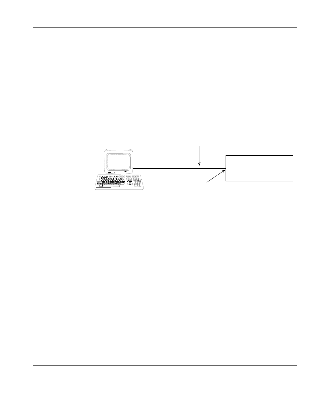
Connecting an ASCII Terminal Device to the Router’s Console Port
Figure 1-1 shows how to connect an ASCII terminal device directly to the router’s
console port. This connection supports local logon to the router’s Technician
Interface.
RS-232-C console cable*
Terminations:
receptacle to plug
VT220
Console
port
Preparing to Upgrade
Bay Networks
Router
Use Cable No. 7525 for FN, ALN, LN, and CN routers.
Use Cable No. 7526 only for AFN routers.
Figure 1-1. ASCII Terminal Device Connected to the Router Console Port
1-9
Page 22

Upgrading Routers from Version 5 to Version 10.0
Connecting a Router to the Network through a Modem
Figure 1-2 shows how to connect a router to the dial network through a Hayescompatible modem. With this configuration, you log on to the router’s Technician
Interface from a remote PC or UNIX workstation. (You configure the PC or UNIX
workstation with an ASCII terminal emulation program and a connection to the
dial network through another Hayes-compatible modem.)
Dial Network
Network interface
cable
*
Use Cable No. 7825 for AFN, FN, ALN, LN, and CN routers.
Modem
RS-232-C modem cable
Terminations: plug to plug
Figure 1-2. Modem Connected to the Router Console Port
Bay Networks
Router
*
1-10
Page 23

Verifying X.25 Certifiability
If the router you want to upgrade does not currently support any X.25
configurations, go to “Reviewing Interoperability Issues.”
If you need to upgrade a Version 5 router supporting X.25 to a Version 10.0 router
supporting X.25, read this section.
Due to possible differences between older and newer link modules supporting
connections to your X.25 network, you must verify that a Version 5 router you
want to upgrade to Version 10.0 can meet X.25 certification requirements. If you
have not done so before receiving this upgrade kit, you may need to replace some
link modules so that the router passes X.25 certification.
Refer to Appendix B for information on the hardware you need to ensure that the
routers you are upgrading meet X.25 certification requirements upon completion
of the upgrade.
Reviewing Interoperability Issues
Before you upgrade from Version 5 to Version 10.0, review the following
interoperability issues between Version 5 and Version 10.0 routers:
Preparing to Upgrade
• Point-to-point connections over a synchronous line
• PPP software
• AppleTalk OUI values for routing over SMDS or Frame Relay
Note: You do not need to remove features unsupported in Version 10.0 from a
Version 5 configuration file.
Refer to Appendix B for more detailed information about these issues, then go to
Chapter 2 or 3 to begin the router upgrade process.
1-11
Page 24

Page 25

Chapter 2
Starting the Upgrade:
Copying Files to Your Personal Computer
This chapter describes how to install or copy the following files to a personal
computer (PC):
• Site Manager Version 4.0 files
• Router Software Version 10.0 files
• Version 5 router files
For instructions on how to copy these files to a UNIX Site Manager workstation,
go to Chapter 3.
Task 1: Installing the Site Manager Software
Follow the instructions provided in Quick-Starting Routers and BNX Platforms to
install your Version 4.0 Site Manager software and Distinct 3.31 TCP/IP software
on a PC.
Site Manager on the PC uses a Windows Socket-compatible TCP/IP stack to
communicate across the IP network. Before you can upgrade Site Manager 4.0 on
your PC, you must first upgrade the TCP/IP stack on that PC. Site Manager ships
with the Distinct TCP/IP for Microsoft Windows software, Version 3.31, a
Distinct Corporation application. Distinct TCP/IP provides an interface between
Site Manager and the TCP/IP network. Earlier versions of Distinct TCP/IP will
not work with Site Manager 4.0 for the PC.
If you use another Windows Socket-compatible TCP/IP stack to support Site
Manager, refer to the user documentation supplied by the manufacturer of the
TCP/IP stack for installation instructions.
2-1
Page 26

Upgrading Routers from Version 5 to Version 10.0
Task 2: Installing the Router Software
Follow the instructions provided in Modifying Software Images for Routers to
install Version 10.0 router software on a Site Manager PC.
Task 3: Backing Up Version 5 Files from Router to PC
Bay Networks recommends that you back up to your PC the software image and
config files currently stored on the router. It is important to maintain backup
copies of these files to ensure that you can restore router operation in case you
encounter malfunctions during the upgrade process.
You back up Version 5 files to your Site Manager PC via diskette or via the IP
network. (In Chapter 4, you use the backup copy of your Version 5 router
configuration file as the source for the conversion utility convert.exe.) Choose the
file backup or transfer method most appropriate for your requirements.
Transferring Files via Diskette
You can physically transport the router diskette with Version 5 configuration files
to your Site Manager PC, then copy the files to the local hard drive. Perform the
following steps:
2-2
1. Enter the following Network Control Language (NCL) command at the
operator’s console of the router you want to upgrade:
remove
Remove the diskette from the diskette drive of the router.
2.
3. Insert the router diskette into the diskette drive of the PC.
4. Copy all files from the router diskette to the desir ed directory on y our PC
hard drive using MS-DOS commands or the Windows File Manager.
For example, copy the files to the \wf\v580backup directory, where v580 is the
version of your router software.
5. Remove the router diskette from the PC’s diskette drive.
6. Reinsert the diskette into the router’s diskette drive.
7. Enter the following NCL command at the router operator’s console:
insert
Page 27

Starting the Upgrade: Copying Files to Your Personal Computer
When you finish transferring files from the router to your PC, go to Chapter 4.
Transferring Files via the Network
You can transfer (back up) Version 5 files from the router to your Site Manager PC
via your IP network using a TFTP-capable application program running on your
PC. When you use the TFTP-capable program, be sure to
• Use the IP address of your router as the host address for the TFTP operation.
• Copy all the files (including those within directories) from the router diskette
volume to the desired directory on your PC hard drive using binary-mode
GET file operations.
For example, transfer the files to the \wf\v580.bkp directory, where v580 is the
version of your router software.
For instructions on how to perform a TFTP binary-mode GET file operation from
your Site Manager PC, refer to the user documentation supplied by the
manufacturer of your TFTP-capable software.
Table 2-1 lists the Version 5 files you must transfer (back up) from the router’s
default file system volume to your PC.
Table 2-1. Version 5 Files to Transfer to the PC
At root level In the /help directory
ace.out atstat.hlp ipxstat.hlp
config bufstat.hlp lbstat.hlp
dmap.out cirstat.hlp ncl.hlp
/help conf.hlp stats.hlp
log dnstat.hlp system.hlp
netboot.out eventlog.hlp t1stat.hlp
vrtx.out ipstat.hlp xrxstat.hlp
When you finish backing up your Version 5 files, go to Chapter 4 to upgrade your
Version 5 files (config and router software image) for use with the Version 10.0
router software.
2-3
Page 28

Page 29

Starting the Upgrade:
Copying Files to Your UNIX Workstation
This chapter describes how to install or copy the following files to a UNIX
workstation:
• Site Manager Version 4.0 files
• Router Software Version 10.0 files
• Version 5 router files
For instructions on how to copy these files to a PC, refer to Chapter 2.
Task 1: Installing the Site Manager Software
Chapter 3
To install Version 4.0 Site Manager software on a UNIX workstation, follow the
instructions provided in Quick-Starting Routers and BNX Platforms.
Task 2: Installing the Router Software
To install your Version 10.0 router software on your Site Manager workstation,
follow the instructions provided in Modifying Software Images for Routers.
Task 3: Backing Up Version 5 Files from Router to Workstation
Bay Networks recommends that you back up to your workstation the software
image and config files currently stored on the router. It is important to maintain
backup copies of these files to ensure that you can restore router operation in case
you encounter malfunctions during the upgrade process.
3-1
Page 30

Upgrading Routers from Version 5 to Version 10.0
Back up your Version 5 files via diskette or via the IP network to your Site
Manager workstation. (In Chapter 4, you use the backup copy of your Version 5
router configuration file as the source for the conversion utility, convert.exe.)
Choose the file backup or transfer method most appropriate for your requirements
and workstation type.
Transferring Files to a Workstation
Table 3-1 describes how to transfer Version 5 files to workstations.
Table 3-1. Transferring Files to a Workstation
For this workstation type Follow these instructions
UNIX workstation with 3 1/2-inch disk
drive that can read DOS diskettes
under the personal computer file
system (pcfs)
IBM RS/6000 and HP 9000 without
3 1/2-inch disk drive
Physically transfer your Version 5 files to that
workstation via router diskette. For this
procedure, go to “Transferring Configuration
Files to a Sun SPARCstation via Diskette.”
Use TFTP to transfer your Version 5 files to the
workstation via your IP network. For this
procedure, go to “Transferring Files via the
Network,” at the end of this chapter.
Transferring Configuration Files to a Sun SPARCstation via Diskette
To transfer your Version 5 files to the local hard drive of your Sun SPARCstation:
1. Enter this NCL command at the operator’s console of the router you
want to update:
remove
Remove the diskette from the diskette drive of the router.
2.
3. Insert the diskette into the diskette drive of the SPARCstation.
4. Get superuser privileges by entering this command at the UNIX prompt:
su
Create a directory for your Version 5 files.
5.
3-2
For example, enter this command at the UNIX prompt, where v580 is the
version number of your router software:
mkdir /usr/wf/v580backup
Page 31

Starting the Upgrade: Copying Files to Your UNIX Workstation
6. Mount the SPARCstation pcfs by entering this command:
mount -t pcfs /dev/fd0 /pcfs
This allows your SPARCstation to read the DOS-formatted diskette from the
router.
7. Copy all of your files from the Version 5 router to the hard drive of the
SPARCstation by entering this command:
cp -r /pcfs/✱
<directory>
<directory> is the directory you created in Step 5 of this procedure.
8. Unmount the pcfs by entering this command:
unmount /pcfs
Eject the diskette from the diskette drive by entering this command:
9.
eject
Remove the diskette from the diskette drive.
10.
11. Insert the diskette into the diskette drive of the router.
12. Enter this NCL command at the router operator’s console:
insert
When you finish transferring the Version 5 files to your UNIX Site Manager
workstation, go to Chapter 4.
Transferring Files via the Network
You can retrieve Version 5 files from the router and transfer them to your UNIX
Site Manager workstation using a TFTP binary-mode GET file operation. For
more information on how to use the UNIX tftp command, refer to your UNIX
system user documentation or online system man pages.
3-3
Page 32

Upgrading Routers from Version 5 to Version 10.0
Table 3-2 lists the Version 5 files you must transfer (back up) from the router’s
default file system volume.
Table 3-2. Version 5 Files to Transfer to the Workstation
At root level In the
ace.out atstat.hlp ipxstat.hlp
config bufstat.hlp lbstat.hlp
dmap.out cirstat.hlp ncl.hlp
/help conf.hlp stats.hlp
log dnstat.hlp system.hlp
netboot.out eventlog.hlp t1stat.hlp
vrtx.out ipstat.hlp xrxstat.hlp
/help
directory
When you finish backing up your Version 5 files, go to Chapter 4 to upgrade your
Version 5 files (config and router software image) for use with the Version 10.0
router software.
3-4
Page 33

Chapter 4
Continuing the Upgrade:
Converting and Customizing Files
This chapter describes how to
• Customize the software image for a router
• Convert Version 5 configuration files from a router
• Verify and further customize converted (upgraded) configuration files
Refer to the following table for the tasks you need to perform to convert and
customize files.
If your Site Manager workstation is a Perform only the instructions in Tasks
DOS PC running Windows 1, 2A, and 3
UNIX workstation 1, 2B, and 3
4-1
Page 34

Upgrading Routers from Version 5 to Version 10.0
Task 1: Customizing the Router Software Image
Note: Before you begin Task 1, read “About Converting Configuration Files.”
Site Manager provides a tool, the Image Builder, that lets you customize a Version
10.0 software image for the Version 5 router that you want to upgrade. To access
the Image Builder, select Tools➔Image Builder from the main Site Manager
window.
Make sure that the image you want to customize resides on the Site Manager
workstation or PC.
To customize a software image:
• Remove any nonessential files (protocols) that you will not use. For example,
you might want to remove specific protocols to make more space a vailable on
the target Flash card (NVFS) volume.
• Add components (protocols) that you removed inadvertently. For example,
you might have remov ed files that you decide you want in the router software
image.
4-2
• Save the customized router software image to your current directory on your
Site Manager workstation or PC.
In addition to customizing a Version 10.0 software image by removing or adding
protocols, you can use the Image Builder tool to do the following:
• Display a router software image as a list of individual components.
• Display the additional router software shipped from Bay Networks as a list of
individual components.
• Report the size of selected files and the projected size of the new router
software image.
• Save an image to a specified directory on your Site Manager workstation or
PC.
• Archive all files loaded into the Image Builder to the directory builder_dir on
your Site Manager workstation or PC.
Page 35

Continuing the Upgrade: Converting and Customizing Files
Refer to Modifying Software Images for Routers for instructions on customizing
the router software image for a router you want to upgrade. When you finish
customizing the router software image, follow the instructions for converting a
Version 5 config file on a PC (Task 2A) or on a UNIX workstation (Task 2B).
About Converting Configuration Files
To transfer a Version 5 configuration file to the router you want to upgrade, you
must first convert the configuration file to a Version 7.56 binary file using the
convert.exe utility.
The Site Manager installation software automatically installs the convert.exe
utility on your Site Manager workstation or PC. The convert.exe utility reads the
existing Version 5 config file, upgrades configuration parameters and related
features in that file, and creates the following new files:
• A Version 7.56 binary configuration file
The convert.exe utility names this file <filename>.v7, where <filename> is
the name of the file it reads (typically config).
• An ASCII report that provides details about each translation mapping
The convert.exe utility names this file <filename>.rpt, where <filename> is
the name of the file it read (typically config) and rpt signifies “report.” Use
this file for troubleshooting only.
When you want to review a config.rpt file for troubleshooting purposes, you can
print the file to the screen or to a printer, or you can display the file using a text
editor.
4-3
Page 36

Upgrading Routers from Version 5 to Version 10.0
The following is an excerpt from a sample config.rpt file created by convert.exe.
-SYSTEM (
+LOCATION=~xyz~System Location = xyz
+CONTACT=~Local User ~System Contact = Local User
-LOGGER=1Enable Logging = Yes
-RESET=1Automatic Reboot = Yes
-AUTO=1Auto Enable = Yes
+NAME=RFS_1_CFG5System Name = RFS_1_CFG5
+SESSION (
+MODE=0Session Mode = User
-REFRESH=3Screen Refresh Rate = 3
-TTYPE=4Terminal = ANSI
+MODEM=0Enable Modem Control = No
+STOPBITS=4Stop Bits = 2
+CHARBITS=8Bit / Char. = 8
+PARITY=0Parity = None
+BAUD=9600Baud Rate = 9600
-XON=1Flow Control = XON/XOFF
-DEVID=2Device ID = Console
-FILTER=4Event Filter Level = Show All Events
)
+SESSION (
+MODE=1Session Mode = Disk Logging
-LOGSIZE=200Log File Size = 200
-FILTER=4Event Filter Level = Show All Events
)
4-4
+SESSION (
+MODE=4Session Mode = Telnet
-REFRESH=3Screen Refresh Rate = 3
-TTYPE=2Terminal = VT100
-DEVID=12Device ID = Telnet
-FILTER=4Event Filter Level = Show All Events
)
-SLOT_MTU (
-SLOT_MTU=1Size = 4852 Bytes
-SLOT=4Slot = 4
Page 37

Continuing the Upgrade: Converting and Customizing Files
To interpret the contents of the config.rpt file, refer to Table 4-1.
Table 4-1. Format of the
Format Symbol Description
Plus (+) sign Precedes each successful parameter translation. The Version 5
Minus (-) sign Precedes each unsuccessful parameter translation.
The convert.exe utility does not provide error checking. Any configuration errors
in the existing config file also appear in the newly upgraded file. Use the Version 5
Configuration Editor to correct errors before converting the file. You can also use
the Version 4.0 Configuration Manager to correct errors after converting the file.
Modifying the Configuration File
Before you convert the Version 5 configuration file, you should delete the
following protocols and related features from the Version 5 configuration file:
• SMDS (Switched Multimegabit Data Service), BOOTP, EGP, IPSO security,
OSI, PPP, TCP, and X.25
• Frame Relay
config.rpt
parameter and setting appear to the left of the first equal sign in
capital letters, and the new (upgraded) Version 7.56 parameter and
setting appear to the right.
File
The Version 10.0 router software cannot use convert.exe output for Frame
Relay circuits originally defined in your Version 5 configuration file.
• PPP synchronous lines
You must delete PPP circuits from any Version 5 config file you want to
upgrade to a Version 7.56 file. After upgrading the Version 5 file, you add the
PPP circuits back into the configuration under Site Manager Version 4.0.
• Traffic filters
Appendix A of this guide contains guidelines for creating Version 10.0 filters.
Configuring Traffic Filters and Protocol Prioritization describes how to use
Site Manager to configure the filters.
• Route filters
4-5
Page 38

Upgrading Routers from Version 5 to Version 10.0
• System records (such as the contact person and location of the router)
The Version 10.0 router software does not support these features. The Site
Manager main menu provides fields for this information.
• Version 5 features that are not supported in Version 7.56
These features are AppleTalk zone filters, source routing hop-count reduction,
and encapsulated SNMP traps.
You delete these protocols and related features from the configuration file because
the convert.exe utility will not upgrade them in its Version 7.56 output file.
File Conversion Considerations
When you are converting configuration files, remember to do the following:
• Verify default parameter settings
If a Version 5 parameter has a default setting and that setting differs from the
default setting in Version 7.56, the parameter automatically adopts the
Version 7.56 default setting. Make sure that you verify all configuration
parameters before booting a converted configuration file on a router.
4-6
• Configure an SNMP community
If you do not have an SNMP community configured in the configuration file
you are upgrading, Site Manager automatically converts your configuration
file to have the SNMP community “public” with a wildcard manager
(0.0.0.0). Bay Networks strongly recommends that you restrict read-write
access to the router. See Configuring SNMP, BOOTP, DHCP, and RARP
Services for details on configuring an SNMP community.
Page 39

Continuing the Upgrade: Converting and Customizing Files
Configuration File Upgrade Procedure Summary
The following steps summarize the upgrade procedure for Version 5 configuration
files:
1. Convert a Version 5 config file to a binary Version 7.56 config file.
Alternatively, you can create a new config file for the router you want to
upgrade. For more information about creating ne w configuration files, refer to
Configuring Routers.
2. Open the new Version 7.56 configuration file and perform the following
functions:
• Re-identify the router’s hardw are configuration (router type, module type
per slot, and so forth) in the file.
• Check for default parameters and correct any new parameter settings in
the file according to your network configuration requirements.
• Add any new Version 10.0 features and traffic filters you want in the file.
3. Use TFTP to transfer the new Version 7.56 configuration file to a router
running Version 10.0 software.
This is the router that you booted off startup.cfg.
4. Boot the router using the converted Version 7.56 configuration file.
5. Save the converted Version 7.56 configuration file to Flash on the router
running the Version 10.0 router software.
Specify a file name other than config (for example, config.new).
This updates the MIB version stamp on the Version 7.56 configuration file to
Version 10.0, resulting in a new configuration file that contains Version 10.0
configuration parameters and features.
6. Save the completed configuration to Flash on the target router.
Note: Steps 3 through 6 of this procedure are described in detail in Chapter 5.
4-7
Page 40

Upgrading Routers from Version 5 to Version 10.0
Task 2A: Converting a Version 5 Configuration File on a PC
To convert a Version 5 config file on a PC to a Version 7.56 configuration file:
1. Open the File Manager from the Program Manager window.
2. Double-click on convert.exe in the appropriate directory.
The Convert Utility window opens.
By default, the convert.exe utility resides in the \wf directory.
3. Select Run from the Action menu.
The Source File Specification window opens.
4. Select the drive that contains the config file in the Drives scroll box.
The drive selection appears at the lower right corner of the window.
5. In the Directories scroll box, select the directory that contains your
configuration file.
6. Select the filename in the File Name scroll box.
For example, if your filename is config, select it in the scroll box. The path to
the filename (for example, \wf\v580backup) appears in the File Name box.
4-8
7. Click on OK.
The convert.exe utility upgrades the config file to a Version 7.56 configuration
file.
During the upgrade, the convert.exe utility displays any incompatibilities it
finds between the Version 5 config file and the Version 7.56 software
requirements on the screen in this format:
Note:
Note: During file conversion, messages generated by the convert.exe utility do
<text of message>
not necessarily indicate a problem in the conversion pr ocess. Incompatibilities
do not prevent translation of the rest of the file.
Page 41

Continuing the Upgrade: Converting and Customizing Files
Example
The following is an example of what you see when you run convert.exe on a
Version 5 config file:
This program will put the version 7 file in: cfg10.v7
and it will put a report on what it translated in:
cfg10.rpt
PLEASE NOTE:
This program is more strict than the router itself when
interpreting configuration files, so you may see messages
that look like:
Note: <text of message> (continuing translation)
This is normal, and does not prevent translation of the
rest of the configuration.
Note: couldn't find OSPF Interface Password for 0.0.0.0
(continuing translation)
Note: couldn't find OSPF Interface Password for 0.0.0.0
(continuing translation)
Note: Making the SNMP Community 'public' Read/Write
(necessary for series7)
Translation completed
8. Click on OK.
If the file conversion is successful, the Control Message window displays this
message:
Config file - c:\<
dumped successfully into the file:
c:\
<pathname>\<filename>
Report dumped successfully into the file:
c:\
<pathname>\<filename>
a. Click on OK, then select Exit from the File menu.
b. Go to “Task 3: Customizing a Converted Configuration File” to add
pathname
.v7
.rp
>\config
the router hardware configuration to the converted file.
4-9
Page 42

Upgrading Routers from Version 5 to Version 10.0
If the conversion fails, a message indicates that the convert.exe utility was
unable to convert your config file due to errors it detected in that file. In this
case, perform the following troubleshooting steps:
a. T ry again to transfer your Version 5 configuration file from the router
to the workstation or PC using TFTP.
b. Convert the file again using the convert.exe utility.
If this proves unsuccessful, use Site Manager to build a new (Version 10.0)
configuration file for the router you want to upgrade.
Task 2B: Converting a Version 5 Configuration File on a UNIX
Workstation
To convert a Version 5 config file to a Version 7.56 configuration file:
1. Select the directory that contains the Version 5 config file.
For example, /usr/wf/v580backup
2. Convert the Version 5 config file using the convert.exe utility.
Enter the following command:
4-10
/usr/wf/bin/convert config
The convert.exe utility displays any incompatibilities it finds between the
Version 5 config file and the Version 7.56 software requirements on the screen
in this format:
Note: <text of message> (continuing translation).
Note: During file conversion, the messages generated by the convert.exe
utility do not indicate a problem in the conversion process. Incompatibilities
do not prevent translation of the rest of the file.
If the conversion succeeds, the Control Message window displays this
message:
Translation completed
Go to “T ask 3: Customizing a Converted Configuration File” to add the router
hardware configuration to the converted file.
Page 43

Continuing the Upgrade: Converting and Customizing Files
If the conversion fails, a message indicates that the convert.exe utility was
unable to convert your config file due to errors it detected in that file. In this
case, perform the following troubleshooting steps:
a. T ry again to transfer your Version 5 configuration file from the router
to the workstation or PC using TFTP.
b. Try again to convert the file using the convert.exe utility.
If this proves unsuccessful, use Site Manager to build a new (Version 10.0)
configuration file for the router you want to upgrade.
Task 3: Customizing a Converted Configuration File
After you convert a configuration file, you must use the Configuration Manager to
re-identify or re-establish the router’s hardware configuration in the resulting
Version 7.56 config file. You do this by restoring the definitions of any link
modules, circuits, protocols, filters, or other features not mapped automatically by
convert.exe into your Version 7.56 configuration file. The Configuration Manager
reassociates the circuit and protocol configurations that existed on those link
modules and slots in the router you are upgrading.
After you re-establish the hardware configuration in the converted configuration
file, you must
• Add an IP interface to the configuration file if it does not already contain one.
• Verify (and, if necessary, adjust) Version 7.56 default settings in the file.
• Add any Point-to-Point circuits deleted just prior to file conversion.
• Upgrade any Frame Relay circuits in the configuration.
• Create traffic filters, if appropriate, for the configuration and location of the
router in your network.
• Inspect the file and make any other corrections you deem necessary.
You also use the Configuration Manager to enhance your converted and redefined
configuration file with new features.
4-11
Page 44

Upgrading Routers from Version 5 to Version 10.0
Identifying the Router Hardware Configuration
This section describes how to use Site Manager to add router type (AFN, LN, CN,
ALN, FN) and link module information to a configuration file that you have
converted successfully.
To add the router’s hardware information to a config file:
1. Start up Site Manager.
• From a UNIX workstation, enter this command
wfsm &
• From a PC, double-click on the PC Site Manager icon.
The Site Manager window opens.
2. Select the Tools option in the menu bar.
The Tools menu opens.
3. Select the Configuration Manager.
A menu appears to the right of the Tools menu.
4-12
4. Select Local File.
The Open Configuration File window opens.
5. Select the filename <filename>.v7 in the scroll box.
6. Click on OK.
A popup window prompts you for the router type.
7. Click on the box identifying the router type. Then select Confirm.
The Configuration Manager window opens, displaying the number of slots on
the router you are configuring. The slots are numbered from the bottom up in
the Configuration Manager window. All VME-based routers have a
SYSCON-II and SYSIO in Slot 1. You must configure all other slots.
Remember that Site Manager displays Slots 1–n as they appear when viewing
the router from the back; that is, the bottom slot is Slot 1, and so forth.
Page 45

8. Select the first available empty slot under the Description column.
A popup window displays the link module types.
9. Click on the appropriate link module. Then click on OK.
Site Manager automatically displays the connector names associated with the
link module you selected.
10. Repeat Steps 8 and 9 for each link module in the router.
11. Select File➔Save As.
The Save Configuration File window appears.
12. Type confighd (for config with hardware) in the Enter File Name box.
13. Select Save in the Save Configuration File window. Then click on OK in
the confirmation window.
Site Manager in local mode saves confighd as a Version 7.56 configuration
file.
Adding an IP Interface
Continuing the Upgrade: Converting and Customizing Files
You must configure an IP interface on the router to enable the router to support a
connection to a Site Manager workstation.
If your
confighd
Includes an IP interface Go to the next section, “Verifying and
Does not include an IP interface 1. Use the Configuration Manager to open the
file Then
Customizing Default Settings.”
file and add the interface.
2. Save the file.
If necessary, refer to
instructions on how to add a new IP interface.
Configuring Routers
for
Later in the Version 5 to Version 10.0 upgrade process, you replace the default
configuration file on the router with a converted or new configuration file that
includes the required IP interface. You provide the IP address of this interface to
Site Manager, which can then establish a connection to the router you want to
upgrade.
4-13
Page 46

Upgrading Routers from Version 5 to Version 10.0
Verifying and Customizing Default Settings
To verify and change default settings in the confighd file:
1. Open the confighd file.
2. Carefully inspect the parameter settings in this file.
Be aware that default settings for some parameters changed between Version
5.xx and Version 10.0.
3. Modify or add new settings to meet your network configuration
requirements.
If you need to Refer to
Redefine PPP circuits deleted before conv erting the
Version 5
Delete and redefine Frame Relay circuits, which do
not upgrade when you run
Restore protocols deleted by
new protocols
Add new (Version 10.0) features “Adding Version 10.0 Features”
Add new (Version 10.0) traffic filters “Adding Traffic Filters”
Do none of the above Chapter 5, to complete the
config
file
convert.exe
convert.exe, or
add
“Redefining Point-to-Point Circuits”
“Redefining Frame Relay Circuits”
“Re-entering and Adding
Protocols”
upgrade to Version 10.0
Note: Save your edits and enhancements to the confighd file.
4-14
Page 47

Continuing the Upgrade: Converting and Customizing Files
Redefining Point-to-Point Circuits
If the router you are upgrading needs to support PPP over a synchronous line, read
this section.
Before running convert.exe, you deleted from your Version 5 config file any
synchronous lines running PPP. If file conversion was successful, you can restore
the synchronous lines running PPP in your new (Version 10.0) config file.
For information on how to use the Configuration Manager to enable PPP on a
synchronous line, refer to Configuring PPP Services.
If you need to configure PPP on a synchronous line between a Version 5 router
and a Version 10.0 router, refer to Appendix B.
Redefining Frame Relay Circuits
If the router needs to support Frame Relay circuits, follow the instructions in this
section.
Deleting and Configuring Frame Relay Interfaces
The upgrade procedure does not convert all Frame Relay circuit records. Some
Site Manager screens will not display unconverted records. You must delete all
interfaces on which Frame Relay was configured and reconfigure them, as
follows:
1. Open the confighd file, which is your most up-to-date configuration file,
using the Configuration Manager.
Note: This file is already open if you followed the steps in the previous section
and did not exit. Note that the filename appears near the top of the window.
2. Select Circuits➔Delete Circuits.
The Circuit List window displays the circuits.
3. Select each circuit on which Frame Relay was configured in the original
Version 5 config file you converted.
4. Select Delete.
5. Select Done.
4-15
Page 48

Upgrading Routers from Version 5 to Version 10.0
For each circuit you deleted in Step 4, select Circuit➔Add Circuit and
6.
reconfigure the circuit.
For information about configuring Frame Relay circuits, refer to Configuring
Frame Relay Services.
7. Save your changes to the confighd file.
Re-entering and Adding Protocols
In “About Converting Configuration Files,” we recommended that you delete the
following protocols and related features from the original Version 5 configuration
file:
• SMDS
• BOOTP
• EGP
• IPSO security
• OSI
• PPP
4-16
• TCP
• X.25 configuration details
If your original Version 5 configuration file included any of these protocols or
related features, you can re-enter them using the Configuration Manager.
To restore deleted protocols or add new protocols to your confighd file, refer to
Configuring Routers and to the configuration guides for those protocols.
Remember to save your changes to the confighd file.
Page 49

Adding Version 10.0 Features
To add Version 10.0 features to the confighd file:
1. Open the confighd file.
2. Manually configure Version 10.0 features that the convert.exe utility does
not support.
Add the new configuration features you want.
3. Save your changes to the confighd file.
Adding T raffic Filters
Before adding any Version 10.0 traffic filters to the confighd file, read Appendix A
to review the differences between the Version 5 and Version 10.0 filtering
implementations and strategies. For details on using Site Manager to configure
filters, refer to Configuring Traffic Filters and Protocol Prioritization.
To add traffic filters:
1. Open the confighd file.
Continuing the Upgrade: Converting and Customizing Files
2. Add any Version 10.0 traffic filters you want in the confighd file using the
Configuration Manager.
3. Save your additions to the file.
4-17
Page 50

Page 51

Chapter 5
Completing the Upgrade:
Transferring and Testing Customized Files
This chapter describes the tasks you need to perform to transfer and test the
customized files. After you have completed these steps, you have completed the
upgrade procedure.
Table 5-1 lists the tasks you must complete to transfer and customize files.
Table 5-1. Transferring and Testing Customized Files
Task
Number Title
1 Booting the Router from a Flash Volume
2 Registering the Backplane Type
3 Configuring an Initial IP Connection
4 Testing the Initial IP Configuration File
5 Transferring a Customized Software Image
6 Testing the Customized Software Image
7 Transferring a Converted (or Replacement) Configuration File
8 Testing the Converted (or Replacement) Configuration File
9 Transferring Scripts to the Router
5-1
Page 52

Upgrading Routers from Version 5 to Version 10.0
Task 1: Booting the Router from a Flash Volume
Before you attempt to boot the router from a Flash volume, ensure that
• You backed up your Version 5 router software image and configuration files,
log files, and any other files critical for router recovery, in case you encounter
problems during the upgrade process. (Refer to Chapter 2 (PC) or Chapter 3
(UNIX workstation) for instructions.)
• You configured the router you want to upgrade to Version 10.0 to boot from a
Flash file system volume.
• The router contains a Flash card and you have inserted the Flash card in the
slot to the right.
• The Flash card contains a Version 7–9.xx router software image, a default
config file, and the ti.cfg file.
Note: If you do not boot the router from a Version 7–9.xx router software
image (ace.out), you cannot transfer the Version 10.0 router software image to
a Flash card from your Site Manager workstation or PC. You must boot your
router from a Flash card that contains Router Software Version 7–9.xx.
5-2
You boot the router from a Version 7–9.xx Flash file system volume to initialize
the Technician Interface on the router. You use the Technician Interface to
• Register the router’s backplane type (Task 2)
• Configure and initialize your initial IP connection (Task 3)
To boot the router from a Flash volume:
1. Press the Reset button on the router.
After the router boots successfully, the Technician Interface welcome
message (or related message your network administrator has substituted)
appears:
Welcome to the Technician Interface
Login:
Page 53

Completing the Upgrade: Transferring and Testing Customized Files
2. At the Login prompt, enter the following command to gain system
administrator access.
Manager
The default Technician Interface prompt ($) appears on your ASCII console
screen after you log in.
3. Go to “Task 2: Registering the Backplane Type.”
Task 2: Registering the Backplane Type
To register the backplane type of your FN, ALN, LN, or CN (not AFN) router
from the Technician Interface:
1. Enter the backplane command, followed by the backplane type
backplane
<type>
<type> is FN, LN, or CN
Note: If you have an LN or ALN router, enter backplane LN
2. Press the Reset button.
After the router boots successfully, the following message appears at the
console:
Welcome to the Backbone Technician Interface
Login:
Caution: Boot the router after entering the
ensures that the backplane type registers. You enter the
backplane command. This
backplane
command
only once during the life of a system controller unless you insert that contr oller
in another FN, ALN, LN, or CN router.
3. Log in to the Technician Interface as Manager.
Continue the upgrade process with “Task 3: Configuring an Initial IP
Connection.”
5-3
Page 54

Upgrading Routers from Version 5 to Version 10.0
Task 3: Configuring an Initial IP Connection
You configure an initial Internet Protocol connection to
• Use the IP network as a medium for transporting your customized image and
converted configuration files from the workstation or the PC to the router.
• Ensure that your Site Manager workstation or PC can communicate with the
router during the remainder of the upgrade process.
Refer to Quick-Starting Routers and BNX Platforms for details on using the
Technician Interface to configure and save an initial IP connection to a file.
Note: Make sure that you save the initial IP configuration as startup.cfg. You
will need this file later in the upgrade procedure.
Task 4: Testing the Initial IP Configuration File
After you save the initial IP connection configuration to a file on the router’ s Flash
card, use Site Manager to establish an IP connection between the workstation or
the PC and the router.
5-4
To establish an IP connection to the router:
1. Display the Site Manager window.
2. Select Options➔Router Connections.
The Router Connections Options window opens.
3. Enter the IP address of the router in the Node Name/IP Address box.
4. Click on OK.
When Site Manager establishes a connection to the router, it closes the Router
Connections Options window and displays the IP address of the router in the
Site Manager window.
Page 55

Completing the Upgrade: Transferring and Testing Customized Files
Task 5: Transferring a Customized Software Image
This section describes how to prepare the router to receive the customized image
and how to transfer the customized image to the router.
Preparing a Router to Receive the Customized Image
Refer to Table 5-2 to find the section that corresponds to your router hardware
configuration.
Table 5-2. Section Corresponding to Your Hardware Configuration
If the number of Flash
cards in the router is Refer to
1 “Preparing a Flash Card to Receive the Customized
Image”
2 “Transferring a Customized Image to the Router”
Preparing a Flash Card to Receive the Customized Image
To prepare a Flash memory card to receive a customized image:
1. Delete the existing router software image from the Flash memory card
using the Router Files Manager.
The filename of the image disappears from the Router Files Manager window.
After you delete the image, compare the “ Available free space” field displayed
in the Router Files Manager window to the “Contiguous free space” field.
Although you deleted a file (in this case, the image), it continues to take up
space until you compact the contents of the Flash card. (See Managing
Routers and BNX Platforms for more information about file compaction.)
2. Compact the contents of the Flash card.
Select Commands➔Compact in the Router Files Manager window.
3. Click on OK in the confirmation window.
An hourglass appears for the duration of the file compaction. After several
minutes, a window displays the following message, where x is the volume you
are compacting:
Last file system command, “compact x:”, finished successfully.
5-5
Page 56

Upgrading Routers from Version 5 to Version 10.0
Click on OK in the message window.
4.
The available free space and contiguous free space are now equal.
Continue to the next section to copy your new, customized Version 10.0 router
software image to the router.
Transferring a Customized Image to the Router
To transfer a customized image file to the router you want to upgrade, use the
Router Files Manager. To access the Router Files Manager, select Tools➔Router
Files Manager in the Site Manager window.
To transfer your customized image to the router:
1. Select File➔TFTP in the Router Files Manager window.
This invok es the TFTP (T ri vial File T ransfer Protocol) software to e xecute file
transfers.
2. Select Put File.
The TFTP Put File window displays the Local Filename box.
5-6
3. Enter the local directory path and filename of the image you customized.
4. Click on OK.
The TFTP Put File window displays the destination volume and filename of
the image in the Remote Filename box.
If you are using a router with two Flash cards, change the volume number in
the Remote Filename box from “1” to “2.” This indicates that you want to
save the file to the second (left) Flash card.
Otherwise, do not change the volume number displayed in the box.
5. Verify that the image filename you transfer to the router you are
upgrading is one of the following:
Router Image Filename
FN, ALN, LN, or CN
AFN (Flash)
ace.out
afn.exe
Page 57

Completing the Upgrade: Transferring and Testing Customized Files
6. Click on OK.
7. Click on OK in the confirmation window.
On UNIX workstations, a window displays the following message:
“wftftp” process started in background [pid 5606]
8. Click on OK.
On UNIX workstations, a window displays the following message:
“wftftp” -h <IP Number> -T 1.500000-...” command completed
successfully [pid 5607]
If Then
The transfer completed successfully. Click on OK.
The Router Files Manager window displays the
image filename in the list of files.
The transfer failed.
*
If the transferred failed, do not reboot the router.
*
1. Recheck your setup for this TFTP operation.
2. Try the transfer again.
If you need assistance, call the Bay Networks
Technical Response Center.
Go to “Task 6: Testing the Customized Software Image.”
5-7
Page 58

Upgrading Routers from Version 5 to Version 10.0
Task 6: Testing the Customized Software Image
To test the Version 10.0 customized software image you transferred to the router
in Task 5, you must
• Boot the router and verify that it booted successfully
• Copy the customized image to primary Flash
Booting the Router
To boot the router:
1. In the Site Manager window, select Administration➔Boot Router.
The Boot Router window opens, displaying default filenames for the router
software image and the configuration file.
If Then
You transferred the image to Volume 2 Click on the box inside the “1:” box and
continue with Step 2.
You did not transfer the image to
Volume 2
Go to Step 3.
5-8
2. Click on “2:” to indicate that you want to boot using the Flash memory
card on the left side of the Flash System Controller board.
The “1:” to the right of the Boot Image field changes to a “2:”. Note that the
volume specification next to the Configuration field is “1:”. Do not change
this volume.
3. Change the name of the file in the Configuration box to startup.cfg.
You created startup.cfg in Task 3.
4. Click on Boot.
Wait a few minutes for the router to finish booting.
5. Verify that the router booted successfully.
Select Vie w➔Refresh Display in the Site Manager window.
Page 59

Completing the Upgrade: Transferring and Testing Customized Files
If the router booted successfully, it establishes a connection and displays system
information (such as the system name, contact, location, description, and MIB
version). This confirms that the router can boot with the customized image.
If Site Manager does not display system information in its main window, the
router did not boot successfully. In this case, perform the following steps:
1. Try again to transfer the customized image to the router (see Task 5).
2. Boot the router again.
If the problem persists, call the Bay Networks Technical Response Center in your
area.
Copying the Customized Image to Primary Flash
After you verify that your router is running the Version 10.0 router software
image, you can copy the customized image from your backup Version 10.0 Flash
card to the primary Flash card. Do this when you are ready to delete the Version
7–9.xx image from your primary Flash card.
Note: If you boot the router without specifying the volume from which to read
the image, and the PCMCIA/Floppy switch is in the PCMCIA position, the
router boots from the image in Volume 1 (the Flash card on the right side of
the Flash System Controller). Volume 2 (the Flash card on the left) currently
contains your customized image, while Volume 1 contains a Version 7–9.xx
router software image.
To replace the existing image in Volume 1 with your customized Version 10.0
image, ace.out or afn.exe (as appropriate for the router):
1. In the Router Files Manager window, delete ace.out (or boot.exe for an
AFN router) from Volume 1.
After you delete the old image, compare the “Available free space” field
displayed in the Router Files Manager window to the “Contiguous free space”
field. You cannot load a file onto the Flash card if the file is larger than the
available “Contiguous free space”.
To make available a maximum amount of contiguous free space, you must
compact the remaining contents of the Flash card. For more information about
file compaction, refer to Managing Routers and BNX Platforms.
5-9
Page 60

Upgrading Routers from Version 5 to Version 10.0
Compact the contents of the Flash card.
2.
Select Commands➔Compact in the Router Files Manager window.
3. Click on OK in the confirmation window.
An hourglass appears for the duration of the file compaction. After several
minutes, a window displays the following message, where x is the volume you
are compacting:
Last file system command, “compact <x>:”, finished successfully.
4. Click on OK in the message window.
The available free space and the contiguous free space are now equal.
5. Display the files on Volume 2 and select the image file (ace.out or afn.exe)
you want to copy.
6. Select Commands➔Copy.
The Router Files Manager displays the source filename in the Copy File
window.
7. V erify that the sour ce filename is 2:ace.out. or 2:afn.exe, then click on OK.
The Copy File window prompts you for the destination filename.
5-10
8. In the Destination field, overtype 2:ace.out with 1:ace.out or 1:afn.exe.
This specifies the new volume and filename you want to give this file.
9. Click on OK.
A confirmation window opens.
10. Click on OK.
The router copies ace.out or afn.exe to Volume 1.
11. Verify that the size of the ace.out or afn.exe file that you copied to Volume
1 matches the size of the ace.out or afn.exe file in Volume 2.
Continue to “Task 7: Transferring a Converted (or Replacement) Configuration
File.”
Page 61

Completing the Upgrade: Transferring and Testing Customized Files
Task 7: Transferring a Converted (or Replacement) Configuration
File
T o transfer your converted and customized configuration file (or your new Version
10.0 configuration file) to the router you want to upgrade:
1. Select File➔TFTP in the Router Files Manager window.
2. Select Put File.
The TFTP Put File window displays the Local Filename box.
3. Enter the local directory path and name of your most up-to-date Version
10.0 configuration file.
4. Click on OK.
The TFTP Put File window displays the destination volume and name of the
configuration file in the Remote Filename box.
5. Change the name of the file in the destination volume to something other
than config.
For example, change the name of the file to config.new.
6. Click on OK.
Caution: Avoid writing over config or startup.cfg until you successfully test
your new customized configuration file (for example, config.new) on the
router.
7. Click on OK in the confirmation window.
A window displays the following message:
“wftftp” process started in background [pid 5606]
8. Click on OK.
A window displays the following message:
“wftftp” -h <IP Number> -T 1.500000-...” command completed
successfully [pid 5607]
9. Click on OK.
The Router Files Manager window displays the name of the configuration file
in the list of files.
5-11
Page 62

Upgrading Routers from Version 5 to Version 10.0
Continue to Task 8 for details on booting your router with the converted (or new
replacement) configuration file.
Task 8: Testing the Converted (or Replacement) Configuration
File
T o test the converted (or replacement) configuration file that you transferred to the
router in Task 7, you must
• Boot the router.
• Verify that the router booted successfully.
• Verify that the router routes traffic according to your configuration.
Booting the Router
To boot the router:
1. In the Site Manager window, select Administration➔Boot Router.
The Boot Router window opens, displaying default filenames for the router
software image and the configuration file.
2. Change the name of the file in the Configuration box to the name of the
converted or customized file that you transferred in Task 7.
3. Click on Boot.
Wait a few minutes for the router to finish booting.
4. Go to the next section to verify that the router booted successfully.
Verifying that the Router Booted Successfully
Verify that the router booted correctly with the new configuration file by selecting
View➔Refresh Display in the Site Manager window.
If the router booted successfully, Site Manager establishes a connection to the
router and displays system information (such as the system name, contact,
location, description, and MIB version). This confirms that the router can boot
with the new converted or replacement configuration file.
5-12
Page 63

Completing the Upgrade: Transferring and Testing Customized Files
If Site Manager does not display system information in its main window, the
router did not boot successfully. In this case, perform the following steps:
1. Reboot the router with your startup.cfg file to re-establish IP connectivity.
2. Examine your customized config file for errors using the Configuration
Manager in local mode.
If the problem persists, call the Bay Networks Technical Response Center in your
area.
Verifying that the Router Routes Traffic According to Your Configuration
Use the Statistics Manager and Events Manager tools to verify that the router
routes traffic according to your configuration.
Refer to Managing Routers and BNX Platforms for details on using these tools.
Replacing the Existing Configuration File with the Version 10.0
Configuration File
To replace the existing configuration file with your converted and edited Version
10.0 configuration file:
1. Open the Configuration Manager in dynamic mode.
2. Select File➔Save As.
The Save Configuration File menu appears.
3. Enter the filename config and select the correct volume where your Flash
card resides.
4. Click on Save.
5-13
Page 64

Upgrading Routers from Version 5 to Version 10.0
Task 9: Transferring Scripts to the Router
Transfer from your Site Manager PC or workstation to the router any Version 10.0
Technician Interface scripts useful for your router configuration. You can use the
scripts to display statistical and configuration information about various router
services, and to display or disable these services.
Technician Interface Script Descriptions
The Technician Interface scripts are .bat and .mnu files that you must transfer to a
memory card in each router you want to upgrade from Version 5 to Version 10.0.
• The .bat file enables you to generate information about a protocol or service
that the router supports.
• The .mnu file enables you to display this information by selecting commands
from menus.
Each script contains all the subcommands required to support the options that it
provides. For a complete list of script files and definitions, refer to Using
Technician Interface Scripts.
5-14
For each router you want to upgrade to Version 10.0, you must transfer a
minimum set of scripts, regardless of which protocol-specific scripts you want to
run on your router (Table 5-3).
Table 5-3. Minimum Set of Scripts to Transfer to a Router
Script Filename Description
show.bat
setpath.bat
menu.bat
main.mnu
monitor.bat
Displays the top-lev el menu from which y ou can select
Helps you isolate problems such as circuits that are not
working, packets that are not being forwarded, and so
forth.
Sets the search path and aliases for the script commands.
Provides a menu from which you can select the script you
want to run.
.bat
files currently on the system.
Displays the same information as the show command, b ut
refreshes the display periodically so you can examine
trends and changes.
Page 65

Completing the Upgrade: Transferring and Testing Customized Files
In addition to the required script files listed in Table 5-3, you can transfer to your
router any protocol-specific scripts to support the protocols on the router you are
upgrading to Version 10.0. For example, if you want to run only IP and Frame
Relay on a router, transfer to that router the following script files: ip.bat, ip.mnu,
fr.bat, and fr.mnu.
Transferring Script Files
Before you transfer scripts, do the following:
1. Compact the Flash card on your router.
Select Command➔Compact from the Router Files Manager window in Site
Manager. This gives you more contiguous free space on a Flash card.
2. Check the size of the scripts you want to transfer to your router.
Verify that the amount of contiguous free space you have on a Flash card in
your router exceeds the size of the scripts to be transferred.
We recommend that you use the Bay Networks implementation of the File
Transfer Protocol (FTP) to transfer script files from your workstation or PC to the
router. This method enables you to load more than one file at a time. For
information on how to load scripts, refer to Using Technician Interface Scripts.
5-15
Page 66

Page 67

Appendix A
Understanding Version 10.0 Traffic Filters
Read this appendix if you previously configured traffic filters using the Version 5
Configuration Editor tool, and you want to convert (re-create) those filters using
the Configuration Manager tool accessible under Site Manager.
This appendix provides
• A list of differences between Version 5 and Version 10.0 traffic filters
• Instructions for converting Version 5 traffic filters to Version 10.0
To create Version 10.0 traffic filters that are identical to your existing Version 5
traffic filters, you must
• Understand the differences between Version 5 filters and Version 10.0 filters,
especially concerning filter precedence levels.
• Identify the fields and ranges of traffic you want to drop, accept, forward,
direct, or log.
Once you have this information, you can use the Configuration Manager to create
the necessary filters. Refer to Configuring Traffic Filters and Protocol
Prioritization for details on creating the filters.
A-1
Page 68

Upgrading Routers from Version 5 to Version 10.0
Comparing Version 5 and Version 10.0 Filters
Table A-1 compares the rules for configuring Version 5 versus Version 10.0 traffic
filters.
Table A-1. Comparing Version 5 and Version 10.0 Traffic Filters
Version 5 Filters Version 10.0 Filters
You can configure inbound traffic filters only. You can configure outbound traffic filters (on
synchronous circuits only), as well as inbound
traffic filters.
You can define multiple filters at the same
precedence level (31 possible levels).
You can identify multiple fields within a filter, and
multiple ranges within each field.
The highest precedence level f or a V ersion 5 filter
is 31; the lowest is 1.
A Rule Number assigned to each filter enables
you to keep track of how many filters you define
on an interface (maximum of 31 filters).
The Rule Number and Precedence Level
assigned to a filter are unrelated numbers.
You can change the precedence level assigned to
a filter.
You configure a drop-all action by specifying a
field plus the action “drop all.”
You must define each filter at a different
precedence level (31 possible levels).
No change.
Precedence levels are reversed. The highest
precedence level for a Version 10.0 filter is 1; the
lowest is 31.
A Filter Number assigned to each filter enables
you to keep track of how many filters you define
on an interface (maximum of 31 filters).
The Filter Number and Precedence Level
assigned to a filter are the same number. Filter
Number 1 = Precedence Level 1 (highest); Filter
Number 31 = Precedence Level 31 (lowest).
You can change the precedence level assigned to
a filter, then Site Manager automatically adjusts
(reassigns) the precedence levels assigned to all
other filters on the same circuit.
You configure the “drop-all” action explicitly by
specifying a field and entering as filter
parameters the minimum and maximum values
possible for that field.
You cannot assign a name to a filter. You can assign a descriptive name to any
inbound or outbound traffic filter.
A-2
Page 69

Understanding Version 10.0 Traffic Filters
Converting Version 5 Combination Filters to Version 10.0 Filters
This section describes how to convert Version 5 combination filters to Version
10.0 filters.
Forwarding Strategy
If your filtering strategy involves forwarding most traffic and dropping only
specified packets, configure filters only for the specific types of traffic you want to
drop.
Firewall Strategy
If your filtering strategy involves blocking most traffic and accepting only
specified packets (a “firewall” strategy), begin with a drop-all filter on the
interface. Add more specific, higher-precedence accept and drop filters to achieve
the desired result on that interface.
The drop-all filter describes the broadest range of packets you need to block from
the interface. From this group of packets, you specify the other, higher -precedence
filters, which create exceptions or “holes” in the drop-all range.
To ensure that all unwanted traffic gets dropped:
1. Choose a field that appears in every packet of the protocol you want to
filter.
2. Determine the length of the field.
3. Determine the maximum possible value of the field.
4. Determine the minimum value of the field.
5. Enter these values when you define the drop-all filter.
A-3
Page 70

Upgrading Routers from Version 5 to Version 10.0
Figure A-1 shows the result of a drop-all filter (filter at Precedence Level 8)
working in combination with more specific, higher-precedence filters (filters at
Precedence Levels 1 through 7) on an interface.
• The fields shown in this example are IP address ranges (although you can
choose any appropriate field).
• The Filtered Result shown at the top of the diagram indicates IP address
intervals over which the interface will drop or accept packets it receives.
• Note that the highest precedence filter in a given address range determines the
final result of combined filtering within that range.
• Note that each precedence level supports only one Version 10.0 filter. (Version
5 software allowed you to configure multiple filters at the same precedence
level.)
A-4
Page 71

Understanding Version 10.0 Traffic Filters
Filtered result:
(address ranges dropped or accepted)
Accept
Accept
Accept
Highest
1
Drop Value
2
3
4
Accept
Range
Accept
Accept
Accept
Drop Range
Key: Addresses
=
dropped
Accept
Range
Accept
5
Higher precedence filters
6
7
8
Drop Range
Accept Range
Accept Range
Drop-all Range (IPaddresses)
Figure A-1. Configuring Version 10.0 Filters on an Interface
A-5
Page 72

Upgrading Routers from Version 5 to Version 10.0
Filter Precedence Reversed in Version 10.0
In Version 5, you could use precedence to override a “drop” filter with an “accept”
filter. The same is true in Version 10.0, but the precedence levels have been
reversed numerically (1 = highest precedence; 31 = lowest precedence).
Site Manager requires you to define filters starting with the highest-precedence
(lowest-numbered) filter, and ending with the lowest-precedence (highestnumbered) filter. For this reason, design the entire combined filtering scheme for
an interface first, then enter each filter, beginning with No. 1, the highestprecedence filter.
Router Performance
If possible, use a strategy that accomplishes your filtering goals mainly with drop
filters, since these result in more efficient router performance.
Example of Version 10.0 Filtering on a Circuit
The following example (Table A-2) uses one drop-all filter and one accept filter
with two specific values. The result of the combination of these filters on a single
circuit is that all inbound packets bearing an address from 192.32.25.00 to
192.32.28.255 are dropped, except for packets addressed for destinations
192.32.28.55 and 192.32.28.70.
A-6
Table A-2. Version 10.0 Filtering on a Circuit
Filter Type
Accept 1 (highest) 1 192.32.28.55 192.32.28.55
Drop 2 (lowest) 2 192.32.25.00 192.32.28.255
Filter Precedence
Level
Filter Number Start of Range End of Range
192.32.28.70 192.32.28.70
Page 73

Appendix B
Interoperability
This appendix describes Version 5 and Version 10.0 interoperability issues that
may be of concern to you, depending on the current configuration of your Version
5 routers. The interoperability issues are
• X.25 certifiability of Version 5 routers
• Point-to-point connections over a synchronous line
• PPP Version 10.0 compatibility with previous versions
• PPP software incompatibilities
• AppleTalk OUI values for routing over SMDS or Frame Relay
Verifying X.25 Certifiability
If you are configuring your router to run X.25, refer to Table B-1, then read this
section.
Table B-1. Configuring a Router to Run X.25
Router Software
Version
Version 7.60 or earlier The behavior of the serial controller chips on link modules
Version 7.60 or later The MK Thompson 5025 serial controller chip in the link
Action
differs slightly from the X.25 standard, making them
noncertifiable in X.25 networks.
modules now performs the LAPB function of X.25. This
change significantly improves performance. However, you
may still need to replace some link modules that have earlier
versions of the MK5025 chip set to ensure that the router
passes X.25 certification.
B-1
Page 74

Upgrading Routers from Version 5 to Version 10.0
Follow these guidelines to ensure that you are using a link module that can pass
X.25 certification:
• Do not upgrade AFN hardware.
• Do not replace link modules delivered after June 1992.
• Upgrade link modules directly attached to the X.25 network that were
delivered before October 1991.
• Inspect only the link modules directly attached to the X.25 network that were
delivered between October 1991 and June 1992. Determine which modules to
replace by removing the link module from the router and reading the revision
level of any MK5025 chip on that module. If the revision level is C03 or later ,
do not replace.
Note: If you need hardware to upgrade your router for X.25 support, order it
from Bay Networks. Specify that the r outer needs this hardware to satisfy X.25
certification requirements.
Configuring Point-to-Point over a Synchronous Line
This section describes how to configure a point-to-point connection using the
Point-to-Point protocol over a synchronous line between a Version 5 and a Version
10.0 router.
HDLC Local/Remote Address Settings
On Version 5 routers, you must designate an HDLC “local address” and “remote
address” at each end of a point-to-point synchronous line. The router at each end
receives packets at the designated local address and send packets to the remote
(destination) address.
For each of these parameters, you use Version 5 NCL to either
• Set an implicit address value of DCE (which the router recognizes as a value
of 0x01) or DTE (0x03).
• Set a unique explicit address value in the hexadecimal range 0x00 to 0x99,
inclusive.
B-2
Page 75

Interoperability
Whatever local-remote address pair you assign at one end of a point-to-point
synchronous line, you reverse on the Version 5 router at the opposite end of the
line. For example, the synchronous circuit on Router A in Figure B-1 has an
explicit local address (LA) value of 0x04 and a remote (destination) address (RA)
of 0x05. In this case, you configure the synchronous circuit on Router B at the
opposite end of the same line with a local address (LA) value of 0x05 and a
remote address (RA) value of 0x04.
Router A Router B
Packets
0x04
LA
Sync Line
0x05
RA
Packets
Figure B-1. Address Assignments on a Point-to-Point Synchronous Line
0x05
0x04
LA
RA
The Version 5 Configuration Guide
• States correctly that you should not use the well-known DCE and DTE values
0x01 and 0x03 for any explicit local or remote address on a point-to-point
circuit
• States erroneously that the local and remote address values are decimal rather
than hexadecimal numbers
On Version 10.0 routers, you use the Version 4.0 Configuration Manager and
follow essentially the same guidelines for local-remote address pair assignments
at each end of a point-to-point synchronous line. The Configuration Manager
allows you to choose 0x02, 0x04, 0x05, 0x06, and 0x07 as (1-byte) explicit v alues
for Local Address or Remote Address in the synchronous line parameters window.
(You can extend an explicit local or remote address value to 2 bytes in length by
enabling the Extended Address parameter under the Sync circuit line parameter
group.)
The Version 10.0 Technician Interface imposes no constraints on the values you
choose for the local-remote address pair.
B-3
Page 76

Upgrading Routers from Version 5 to Version 10.0
Point-to-Point Configuration Guidelines
If you want to configure a point-to-point synchronous line between a Version 5
and a Version 10.0 router, follow the guidelines in Table B-2 and in the subsection
that follows.
Table B-2. Point-to-Point Configuration Guidelines
If you need to Then
Configure a synchronous circuit on the local
router to DTE
Configure a synchronous circuit on the local
router to DCE
Use explicit values for the local-remote
address pair
Configure the synchronous circuit on the router at the other
end of the same synchronous line to DTE as well.
Configure the synchronous circuit on the router at the other
end of the line to DCE as well.
Limit your selections to 0x02, 0x04, 0x05, 0x06, and 0x07 at
each end. Ho w ever, if this constr aint pro ves impractical due
to the requirements of your existing Version 5 router and
network configuration, use the Technician Interface on the
Version 10.0 router to
• Override Version 4.0 Configuration Manager explicit
local-remote addressing constraints for Version 10.0
routers.
• Match (and reverse) the V ersion 5 local-remote address
assignments on your Version 10.0 router.
Connecting a Version 10.0 Router to a Version 5 Router
To connect a Version 10.0 router to a Version 5 router, point-to-point over a
synchronous line, enter the following commands at the Technician Interface:
s wfSyncEntry.wfSyncLocalAddress.
commit
s wfSyncEntry.wfSyncRemoteAddress.<
commit
<slot>.<connector> <integer value>
slot
>.<
connector
> <
integer value
;
>;
B-4
save config
<slot>.<connector>
<config name>
is the slot and connector (that is, the synchronous circuit) you
want to configure.
<integer value>
is any explicit address value in the range 0x00 to 0x99, e xcluding
0x01 (the DCE setting) and 0x03 (the DTE setting).
Page 77

The Version 5 synchronous circuit BOFL timer has a default value different from
the Version 7–9.xx BOFL default value. Version 5 routers use a synchronous
circuit BOFL default value of 10. Version 7–9.xx routers have a synchronous
circuit BOFL default value of 5, but you can change it to match the BOFL v alue of
the Version 5 router at the opposite end of the synchronous line.
PPP Version 10.0 Compatibility with Previous Versions
A router running the Bay Networks Version 10.0 PPP implementation
communicates with a router running Version 9.0x using the Link Control Protocol
(LCP) on each line, just as if both routers were running Version 9.0x. In this case,
the routers use either random or address-based load-balancing algorithms. A
multilink circuit using PPP cannot communicate with a router running a version
earlier than 9.00 because versions earlier than 9.00 use a multiline circuit in which
LCP is run on only one line.
PPP Software Incompatibilities
If you need to configure PPP to run over a point-to-point connection between a
Version 5 and a Version 8.xx–10.0 router, you need to read this section.
Interoperability
Version 5.x router software uses a Bay Networks proprietary implementation of
PPP. Version 7–10.0 routers support a new implementation of PPP. The new
implementation complies with the established requirements of Internet RFCs
1331, 1333, 1548, and 1661. Version 10.0 routers also support the multilink
feature, described in RFC 1717.
With the different implementations of PPP, each adhering to a different set of
RFCs, the following functions will not work between a Version 5.x and a
Version 9.xx or 10.0 router:
• Link Quality Monitoring (LQM)
• Source-routing over Token Ring networks
B-5
Page 78

Upgrading Routers from Version 5 to Version 10.0
For communication over a synchronous line between a Version 5 router running
PPP and a Version 10.0 router running PPP, make the following configuration
checks:
• On the Version 10.0 router
— The type of synchronous line service (MIB object ID
1.3.6.1.4.1.18.3.4.5.1.18, wfSyncService) must have a value of
Transparent. (This is the default setting for the Service parameter in the
Edit Sync Parameters window. To access the parameter through the
Configuration Manager, click on the appropriate synchronous connector
and select Edit Line Details.)
• On the Version 5.x router
— The LQM Time parameter must have a value of 0, which disables Link
Quality Monitoring on the Version 5.x router.
— The Quality of Service parameter must have a value of LLC1, the default
setting.
For information on how to check these Version 5.x parameters, refer to your
Version 5.x configuration guide.
AppleTalk OUI Values for Routing over SMDS or Frame Relay
Bay Networks routers running software earlier than Version 5.77 and configured
to route AppleTalk over SMDS or Frame Relay use an Organizationally Unique
Identifier (OUI) value of 0 instead of 0x080007, the value appropriate for
Datagram Delivery Protocol (DDP) packets. Your router supports the correct OUI
value upon completion of the upgrade to Version 10.0.
B-6
Page 79

Glossary
ace.out
afn.exe
an.exe
asn.exe
bn.exe
booting
BOOTP
config
Directed Netboot
DLCMI
DOS
Router software image containing executable files used to boot FN, LN, ALN,
AFN with diskette, and CN routers.
Router software image containing executable files used to boot an AFN router.
Router software image containing executable files used to boot an AN or ANH
router.
Router software image containing executable files used to boot an ASN router.
Router software image containing executable files used to boot a BN router.
The process in which a device obtains information and begins to process it to
attain a state of normal operation.
Bootstrap Protocol, a TCP/IP network protocol that lets network nodes request
startup and configuration information from a BOOTP server node.
Network configuration file containing proprietary protocol services code.
Bay Networks procedure for getting router startup files from a TFTP server on
the IP network.
Data Link Control Management Interface. Specification for the use of Frame
Relay products that defines a method of exchanging status information between
devices.
The primary disk operating system used by IBM and compatible personal
computers.
driver
dynamic
Ethernet
A hardware device or program that controls or regulates another device.
The ability of a display or view to change as a result of ongoing network activity.
Type of network cabling and signaling that operates at the data link layer of the
OSI model.
Glossary-1
Page 80

Flash Memory
Removable Personal Computer Memory Card International Association
(PCMCIA) standard memory card. The ASN uses a Flash memory card to
provide storage for its nonvolatile file system (NVFS), called the local file
system.
Frame Relay
freboot.exe
frediag.exe
HDLC
image
IP
Local Boot
MB
MIB
modem
Standard, connection-oriented protocol for use between data terminal equipment
and data communications equipment. Frame Relay complies with the ANSI
Annex D and LMI Frame Relay management specifications, along with the
CCITT (now ITU-T) Annex A specification.
Copy of the bootstrap image resident on the Boot PROM for the BCN and BLN
router.
Copy of the diagnostic image resident on the Diagnostic PROM for the BCN and
BLN.
High-Level Data Link Control, a protocol that provides error correction at the
data link layer.
One or more executable files used to boot a router; for example, asn.exe.
The Internet Protocol defined in RFC 791.
Bay Networks procedure for getting router startup files from the file system
stored in local Flash memory.
Megabytes.
Management Information Base. A standard or proprietary database that contains
network configuration parameters and statistics.
A modulator-demodulator, a device that converts digital signals used by
computers to analog signals that can be transmitted over telephone lines, and
vice versa.
MS-DOS
multicast packets
Netboot
node
packet
Glossary-2
Microsoft Disk Operating System. A v ersion of DOS used by computers that are
compatible with IBM personal computers.
Targeted broadcast packets sent to a defined group.
Bay Networks procedure for getting router startup files from a BOOTP server on
the IP network.
On local area networks, a device that is connected to the network and is capable
of communicating with other network devices.
A unit of data sent across a network.
Page 81

Ping
A program that is useful for testing and debugging networks. Ping sends an echo
packet to the specified host and waits for a response. It then reports success or
failure and statistics about its operation.
PPP
router
Site Manager
SNMP
stack
Telnet
Technician
Interface
TFTP
Windows
WinSock
Point-to-Point Protocol, a protocol that provides a way of running IP over serial
lines. It uses a variation of HDLC.
A device that connects two or more networks and can direct traffic based on
network resource availability.
Bay Networks network management application. It is an SNMP-based graphical
user interface used by network administrators to manage Bay Networks routers.
Simple Network Management Protocol, a network management protocol on
TCP/IP networks.
A group of drivers that work together to span the layers in the network protocol
hierarchy.
Internet standard protocol for remote terminal connection service. Telnet is
described in RFC 854.
A software command-line interface, operating in router memory, that
administrators use to manage Bay Networks routers.
Trivial File Transfer Protocol. A protocol that enables file sharing over TCP/IP
networks.
Microsoft Windows, the graphical user interface on which the router software
runs.
Windows Sockets. An application programming interface (API) support for IP
environments.
Glossary-3
Page 82

Page 83

A
Index
accept filters, A-3
access to router, read-write, 4-6
adding
hardware, 4-12
IP to a config file, 4-13
AppleTalk, 1-11
ASCII
reports
printed/displayed for troubleshooting, 4-5
asn.exe image. See also image, software
available, 1-3
B
backplane command, 5-3
backplane type registration, 5-3
backplane, registering, 5-3
Bay Networks
Convert Utility window, 4-8
Bay Networks publications, ordering, xviii
blocking filters, A-3
boot
from a converted config file, 5-12
from a customized image, 5-8
from default file, 5-2
image, 5-8
option, 5-8
PROM versions, 1-3, 1-4
BOOTP, 4-5, 4-16
BOOTP server, definition of, Glossary-1
C
certification, X.25, 1-11, 3-1
circuit
configuration, 4-11
community, SNMP, 4-6
compact memory, 5-5
compatibility between Version 5 and Version 8.x
routers, 1-11
confighd file, 4-13, 4-15, 4-17
configuration
booting from a converted file, 5-12
circuit, 4-11
editor, 4-5
file
adding an IP interface to, 4-13
conversion on a PC, 4-8
conversion on a UNIX workstation, 4-10
conversion, resultant default settings, 4-14
conversion/upgrade, 4-1
customizing after conversion to Version 8,
4-11
router hardware identification, 4-12
transfer from remote routers, 2-3, 3-3
transfer to a PC, 2-2
transfer to a UNIX workstation, 3-1
filters, A-5
hardware, 4-12
initial IP connection, 5-4
Manager, 4-5
parameters, 4-6
saving a converted file, 5-13
configuration file
Index-1
Page 84

deleting protocols and related features, 4-5
configuration file, definition of, Glossary-1
connection
cabling ASCII console to router, 1-11
initial IP, 5-4
Site Manager to router via IP, 5-4
console, ASCII, 1-11
contiguous free space, 5-5
contiguous freespace, 1-3
conversions, resulting from v5 file, 4-14
convert
.exe
capabilities, 4-4
error checking, 4-5
installation, 4-3
resultant output, 4-3
config files, 4-1
filters
version 5 to version 8.10, A-3
converted config file
booting from, 5-12
customizing, 4-11
on a PC, 4-8
on a UNIX workstation, 4-10
saving, 5-13
copy
config files
Version 5, 3-1
via diskette to PC, 2-2
via diskette to SPARCstation, 3-2
via TFTP to PC, 2-3
via TFTP to workstation, 3-3
customized image to primary Flash, 5-9
files
to your PC, 2-1
to your UNIX workstation, 3-3
correcting file conversion errors, 4-5
customized image
booting with, 5-8
copying, 5-9
transferring, 5-6
verifying, 5-5
customizing
converted config files, 4-11
router software, 4-2
D
Datagram Delivery Protocol (DDP), B-6
default
file
booting the router from, 5-2
settings after config file conversion, 4-14
differences between Version 5 and Version 8.x,
4-6
documentation required, 1-6, 1-7
driver
defininition of, Glossary-1
drop
action, A-2
filter, A-3
traffic
firewall strategy, A-3
forwarding strategy, A-3
E
EGP, 4-5, 4-16
error checking, convert.exe, 4-5
errors, correcting after file conversion, 4-11
Ethernet, Glossary-1
F
features
not upgraded automatically via convert.exe,
4-5
unsupported, 1-11, 4-15, A-6
file
config testing after conversion/customization,
5-1
confighd, 4-13, 4-14, 4-15, 4-17
Index-2
Page 85

filters
accept, A-3
blocking, A-3
configuring, A-5
converting version 5 to version 8.10, A-3
converting/recreating, A-1
drop-all, A-3
effects on router performance, A-6
firewall strategy, A-3
forwarding strategy, A-3
inbound traffic, A-2
maximum number per interface, A-2
precedence levels, A-2
precedence reversal in v8.x, A-6
route, 4-5
rule numbers, A-2
traffic, 4-5, A-1
flash
compacting, 5-5
copying the customized image to, 5-9
Flash memory
defined, Glossary-2
Flash memory, definition of, Glossary-2
Frame Relay, 1-11, 4-5
defined, Glossary-2
Frame Relay, definition of, Glossary-2
free space on a Flash volume
contiguous, 1-3
copying to primary flash, 5-9
names, 1-3
preparing router to receive, 5-5
transferring an, 5-6
verifying an, 5-5
image, software
defined, Glossary-2
inbound traffic, A-2
Initial IP connection, 5-4
initial preparations for upgrading, 1-5
installing
router software, 2-1, 3-1
Site Manager 2.10
on a PC, 2-1
on UNIX, 3-1
interoperability, 1-11, B-2
IP
adding to a config file, 4-13
initial connection, 5-4
verifying initial connection config, 5-4
IPSO, 4-5, 4-16
L
link modules
hardware requirements for X.25 certification,
1-11
identifying in converted config, 4-12
H
hardware
identifying router in config files, 4-12
link modules for X.25, 1-11
minimum requirements, 1-2
HDLC encapsulation, Glossary-2
I
image
boot, 5-8
booting from an, 5-8
M
manually performed config upgrades, 4-5
memory
card, 5-8
compacting, 5-5
flash, 5-4, 5-9, Glossary-2
MIB
defined, Glossary-2
Index-3
Page 86

N
names
image, 1-4
NCL command, 3-2, 3-3
Network Control Language, 2-2
O
Organizationally Unique Identifier (OUI), 1-11,
B-6
OSI, 4-5, 4-16
P
PCMCIA/Floppy switch, 1-2, 5-9
performance, router with filters, A-6
physical connection to router, 1-11
PPP, 4-5, 4-16
PPP wide-area protocol, Glossary-3
precedence
filter, A-6
level, A-2
reversal in v8.x, A-6
printing/displaying ASCII report, 4-5
public community, SNMP, 4-6
publications required for upgrading a router, 1-6
R
read/write access, 4-6
recreating filters, A-1
registering backplane type, 5-3
registering the router backplane type, 5-3
requirements
boot PROM version, 1-3
for upgrading, xiii, 3-1
hardware configuration and revision lev els, 1-2
physical connection from ASCII console to
router, 1-11
publications, 1-7
X.25 certification, 1-11
route filters, 4-5
router
booting
from a customized image, 5-8
from v7.x/v8.0x default file, 5-2
from v8.10, 5-8
hardware, identification in config files, 4-12
installing image on a PC, 2-2
IP connection to Site Manager, 5-4
software
image names, 1-3, 1-4
installing, 2-2
on UNIX workstations, 3-1
installing on a PC, 2-1
installing on a UNIX workstation, 3-1
type, 4-12
Router Files Manager, 5-5
router software image. See image, software
rule number, filter, A-2
S
saving
a converted config file as default file, 5-13
scripts, TI, 5-14
Site Manager, Glossary-3
installing
on a PC, 2-1
on a UNIX workstation, 3-1
SMDS, 1-11, 4-5, 4-16
SNMP (Simple Network Management Protocol),
4-6
software
installing
router software, 2-2
router software on a UNIX workstation, 3-1
Site Manager 2.10 on UNIX, 3-1
Site Manager on a PC, 2-1
media, 1-8
Index-4
Page 87

verifying the image, 5-5
Source File Specification window, 4-8
starting the upgrade, 2-1, 3-1
startup requirements, 1-6
system records, 4-6
T
TCP
not upgraded via convert.exe, 4-5
restoring, 4-16
Technician Interface, Glossary-3
testing
a customized image, 5-5
converted/replacement config files on router,
5-12
TFTP
defined, Glossary-3
to PC, 2-3
to UNIX workstation, 3-3
TI scripts, minumum required to be transferred to
router, 5-14
tools
Configuration Manager, 4-5
traffic
dropping/blocking strategy for filtering, A-3
filters, 4-5, A-1
forwarding strategy for filtering, A-3
inbound filters, A-2
undesireable
See also "filters", A-3
transferring
converted/replacement config files to router,
5-11
customized image to router, 5-6
files to a PC, 2-2
files to a PC via TFTP, 2-3, 3-3
TI scripts, 5-14
v5 files to a workstation, 3-1
U
unsupported features, 1-11
unwanted traffic, A-3
upgrade
config files, 4-1
kit, 1-8
precautions, 1-2
requirements, xiii, 3-1
software media, 1-8
starting the, 2-1
using UNIX workstations, 3-1
upstream router
defined, Glossary-3
V
verifying
a customized image, 5-5
initial IP connection file, 5-4
version
5.77, B-6
Configuration Editor 5.x tool, A-1
converting filters, A-3
Version 5
config files, copying, 2-1, 3-1
features not supported in Version 8.x, 4-6
X
X.25
certification, 1-11, 3-1
link modules certifiable, 1-11
not upgraded via convert.exe, 4-5
restoring to config, 4-16
Index-5
Page 88

 Loading...