

Avaya Octel 50 Installation Manual

Octel 50
Installation Guide
Octel Messaging
585-313-134
Comcode 108503004
101-1840-000
Issue 1
June 1999


Octel 50
Installation Guide
585-313-134
Comcode 108503004
101-1840-000
Issue 1
June 1999

Copyright © 1999 Octel Communication Corporation, a subsidiary of Lucent
Technologies Inc. All Rights Reserved. Printed in the U.S.A.
Notice
Every effort was made to ensure that the information in this book was complete and
accurate at the time of printing. However, information is subject to change without notice.
Your Responsibility for Your System’s Security
Toll fraud is the unauthorized use of your telecommunications system by an unauthorized
party, for example, persons other than your company’s employees, agents,
subcontractors, or persons working on your company’s behalf. Note that there is a risk of
toll fraud associated with your telecommunications system and, if toll fraud occurs, it can
result in substantial additional charges for your telecommunications services.
You and your system manager are responsible for the security of your system, such as
programming and configuring your equipment to prevent unauthorized use. The system
manager is also responsible for reading all installation, instruction, and system
administration documents provided with this product in order to fully understand the
features that can introduce risk of toll fraud and the steps that can be taken to reduce that
risk.
The manufacturer does not unconditionally warrant that this product is immune from or
will prevent unauthorized use of common-carrier telecommunications services or facilities
accessed, or any charges that result from such unauthorized use.
Trademarks
Touch-Tone is a registered trademark of American Telephone and Telegraph Company.
Dialogic is a registered trademark of Dialogic Corporation.
Rhetorex is a registered trademark of Rhetorex, Inc.
TR112 is a trademark of Brooktrout Technology. Inc.
Sentinel is a registered trademark of Rainbow Technologies, Inc.
Microsoft, MS-DOS, Windows, and Windows NT are registered trademarks of Microsoft
Corporation.

FCC Part 15 Requirements
The components of the Octel 50 system described in this manual have been deemed to
comply with FCC Part 15.
Octel 50 equipment has been tested and found to comply with the limits for Class B
computing devices in accordance with the specifications in Subpart J of Part 15 of the
FCC rules. These specifications are designed to provide reasonable protection against
interference.
Some telephone companies require you to notify them if you connect electronic
communications equipment to the telephone lines. Provide the telephone company with
the FCC registration and Ringer Equivalence Numbers (REN). The sum of the RENs from
all equipment on one phone line must be less than 5. Note that the Octel 50 ringer
equivalence is approximately 0.5.
FCC Part 68 Requirements
The components of the Octel 50 system described in this manual have been deemed to
comply with the requirements of Part 68 of the FCC rules. Octel 50 equipment has a label
that contains the FCC registration and Ringer Equivalence Numbers (RENs) for the
board.
Some telephone companies require you to notify them if you connect electronic
communications equipment to the telephone lines. Provide the telephone company with
the FCC registration and Ringer Equivalence Numbers. The sum of the RENs from all
equipment on one phone line must be less than 5. Note that the Octel 50 ringer
equivalence is approximately 0.5.
The REN is used to determine the number of devices you can connect to the telephone
line and still be assured that all of those devices ring properly when the number is called.
In most areas, the sum of the RENs of all devices should not exceed 5. To be certain of
the number of devices you may connect to the line as determined by the RENs, call the
local telephone company and request information on the maximum REN for the calling
area.
The local telephone company must be notified prior to installation that you are connecting
a registered device to the phone system. You must also provide the following information
to the telephone company for it to select the correct type of service for its lines:
•
Service type: Loop Start or Ground Start—see paragraph 4.1 of the Configuration
Note for the switch
•
Jack required: Multiple RJ-14
•
Order in which you want incoming lines to be when they are connected to the
jacks
•
Ringer Equivalence Number: 0.5A
The telephone company may make changes in its technical operation or procedures. If
these changes affect the use of this equipment, the telephone company is required to
provide you advance notice.

Ordering Information
Use the following information when ordering additional copies of this manual:
Call: Lucent Technologies BCS Publications Center
Voice 1-800-457-1235
Fax 1-800-457-1764
International Voice 1-317-322-6791
International Fax 1-317-322-6849
Write: Lucent Technologies BCS Publications Center
2855 North Franklin Road
Indianapolis, IN 46219
Order: Document No. 585-313-134
Comcode 108503004
Issue 1.0, June 1999
How to Comment on This Manual
Use the feedback form located after this section to send your comments and
recommendations for changes.

Customer Feedback Form
We would like to hear from you about the quality of the documentation, products, and service. Your
comments will help us provide increased satisfaction t o our cu st omer s . Would you please take a
few minutes and complete the following questionnaire and fax it to 303-538-1741.
Please rate the effectiveness of this Implementation and Service Manual in the following areas:
Area Excellent Good Fair Poor
1 Organization
2 Clarity
3 Completeness
4 Accuracy
5 Illustrations
6 Overall satisfaction
Please provide any other comments.
Document:
Products:
Service:


Table of Contents
Chapter 1 - Installation Overview.................................................................. 1-1
Octel 50 System Overview..........................................................................................1-2
Related Documentation...............................................................................................1-2
Chapter 2 - Determining System Needs .......................................................2-1
Step 1: Determining the System Application and Requirements............................... 2-2
Step 2: Determining the Hardware Requirements .................................................... 2-3
Hard Drive Size..................................................................................................... 2-3
CPU and Memory Requirements.......................................................................... 2-3
Step 3: Consider Additional Hardware Needs........................................................... 2-4
Monitor.................................................................................................................. 2-4
3½-inch Floppy Drive ............................................................................................ 2-4
Parallel Port........................................................................................................... 2-4
Serial Port (Optional)............................................................................................. 2-4
Mouse ................................................................................................................... 2-4
Printer (Optional)................................................................................................... 2-5
Modem (Optional) ................................................................................................. 2-5
Tape Backup (Optional) ........................................................................................ 2-5
Voice Boards......................................................................................................... 2-5
Brooktrout TR112 Fax Boards (Optional) ............................................................. 2-5
Uninterruptible Power Supply (Optional)............................................................... 2-5
Chapter 3 - Installing the Hardware..............................................................3-1
Step 1: Assembling All Materials............................................................................... 3-2
Materials Checklist................................................................................................ 3-2
Step 2: Verifying Phone System Readiness.............................................................. 3-3
Confirming Dial Tone ............................................................................................ 3-3
Verifying the Phone System Configuration............................................................ 3-3
Compiling Phone System Configuration Information ............................................ 3-3
Step 3: Configuring the Voice Boards ....................................................................... 3-3
Configuring Dialogic Boards.................................................................................. 3-4
Configuring Rhetorex Boards................................................................................ 3-6
Step 4: Configuring the Fax Boards .......................................................................... 3-7
Configuring Brooktrout TR112 Boards.................................................................. 3-8
Setting the TR112 Port Address ...................................................................... 3-8
Setting the TR112 Board’s Hardware Interrupt Level ...................................... 3-9
Setting the TR112 Board’s DMA Channel ....................................................... 3-9
Step 5: Installing the Voice and Fax Board(s) in the PC ........................................... 3-9
Step 6: Connecting the Telephone and Fax Lines .................................................. 3-10
Connecting the Voice Boards.............................................................................. 3-10
Connecting the Fax Lines ................................................................................... 3-10
Understanding Transfer Method vs. Non-Transfer Method........................... 3-11
Connecting the TR112 Board for the Transfer Method.................................. 3-12
Connecting TR112 Boards for the Non-Transfer Method.............................. 3-12
Step 7: Installing the Serial Integration Device......................................................... 3-12
Octel 50 Installation Guide
I

TABLE OF CONTENTS
Step 8: Installing the Uninterruptible Power Supply ................................................ 3-13
Step 9: Installing and Testing Other Peripherals..................................................... 3-13
Step 10: Installing the Sentinel................................................................................ 3-13
Chapter 4 - Installing the Software ............................................................... 4-1
Verifying the PC is Ready for Installation....................................................................4-2
Making Backup Copies of Software............................................................................4-2
Installing Octel 50 Software.........................................................................................4-3
Confirming Files ..........................................................................................................4-6
Sample Files ..........................................................................................................4-7
AUTOEXEC.BAT..............................................................................................4-7
CONFIG.SYS....................................................................................................4-8
RUNSMO3.BAT................................................................................................4-8
Editing the AUTOEXEC.BAT, CONFIG.SYS, RUNSMO3.BAT Files ....................4-9
Defining an Alternate Keypad Format .........................................................................4-9
Octel 50 System Files ...............................................................................................4-10
Chapter 5 - Running the SMDI Utility............................................................ 5-1
Installing the SMDI Utility.............................................................................................5-2
Running SMDI as a Standalone Utility ........................................................................5-3
Chapter 6 - Configuring Dial Plan.................................................................6-1
Identifying Local Area Code and Prefixes ...................................................................6-2
Running Dial Plan After Installation.............................................................................6-2
Deleting a Prefix..........................................................................................................6-3
Activating Dial Plan ................................................................................................6-3
Understanding How Dial Plan Works.....................................................................6-4
Chapter 7 - Integrating with the Phone System...........................................7-1
Running the Switch Integrator Utility ...........................................................................7-2
Running the Switch Integrator After Installation ..........................................................7-3
Chapter 8 - Setting Up the System................................................................8-1
Running System Setup................................................................................................8-2
Running System Setup After Installation.....................................................................8-3
Configuring System Setup Parameters.......................................................................8-3
General Parameters...............................................................................................8-3
Receptionist Parameters........................................................................................8-7
General Transfer Parameters..............................................................................8-12
Time/Date Parameters.........................................................................................8-13
Message Timing Parameters...............................................................................8-15
Subscriber Parameters ........................................................................................8-18
Caller Parameters ................................................................................................8-22
AMIS Parameters.................................................................................................8-23
Fax Parameters ...................................................................................................8-35
Fax Extensions.....................................................................................................8-40
Call Queuing Parameters.....................................................................................8-41
Intercom Paging Parameters...............................................................................8-45
Octel 50 Installation Guide
II

TABLE OF CONTENTS
Call Transfer Parameters.....................................................................................8-48
Call Screening Parameters ..................................................................................8-55
Call Waiting Parameters......................................................................................8-58
Dialing Parameters...............................................................................................8-59
Message Delivery Parameters.............................................................................8-62
Message Waiting Light Parameters.....................................................................8-64
Uninterruptable Power Supply Parameters..........................................................8-68
Inband Signaling Parameters...............................................................................8-68
Inband Code for Go to Voice Mail........................................................................8-71
Inband Code for Go to Immediate Record...........................................................8-74
Inband Code for Go to Immediate Transfer to Extension ....................................8-76
Inband Code for Go to Immediate Subscriber Login to Mailbox ..........................8-78
Inband Code for Busy Extension..........................................................................8-80
Inband Code for No Answer Extension................................................................8-82
Inband Code for Go to Voice Mail and Get Mailbox.............................................8-84
Inband Code for Go to Automated Attendant and Get Mailbox ...........................8-85
Inband Code Default............................................................................................8-86
Hangup Detection Parameters.............................................................................8-88
Channel Specific Parameters ..............................................................................8-91
PC Configuration Parameters ..............................................................................8-97
Simplified Message Desk Interface Parameters..................................................8-99
Low-Level Voice Board Parameters...................................................................8-100
Chapter 9 - Defining Phone System Signals ................................................ 9-1
Running Call Analysis..................................................................................................9-2
Determining If You Should Run Call Analysis........................................................9-2
Meeting the Requirements to Run Call Analysis....................................................9-2
Using CCA for Rhetorex and Dialogic Boards .......................................................9-3
Running CCA After Installation ..............................................................................9-6
Running AccuCall–Call Analysis for Rhetorex ............................................................9-6
Common AccuCall Problems/Solutions ...............................................................9-13
Running Call Progress Characterization (CPC) Call Analysis for Dialogic................9-14
Chapter 10 - Integrating with an Unterruptible Power Supply.................. 10-1
Understanding UPS Integration.................................................................................10-2
Running UPS Integration...........................................................................................10-3
Chapter 11 - Setting Up the Fax Retrieval Utility .......................................11-1
Understanding Fax Retrieval.................................................................................... 11-2
Adding Fax Retrieval Documents into the Brooktrout System ................................. 11-2
Changing a Fax Retrieval Document Number ......................................................... 11-3
Setting Up a Header or Footer Page for the Brooktrout Board................................ 11-4
Activating Fax Retrieval............................................................................................ 11-4
Chapter 12 - Maintaining the System..........................................................12-1
Starting and Shutting Down Octel 50 ....................................................................... 12-2
Starting Octel 50 ................................................................................................. 12-2
Shutting Down Octel 50 ...................................................................................... 12-2
Octel 50 Installation Guide
III

TABLE OF CONTENTS
Adding Additional Boards to the System.................................................................. 12-2
Adding Rhetorex Boards..................................................................................... 12-2
Adding Dialogic Boards....................................................................................... 12-3
Using Quick Assist ................................................................................................... 12-3
Verifying Octel 50 File Integrity ........................................................................... 12-4
Running a Partial Mailbox Update....................................................................... 12-5
Running an Update on All Mailboxes.................................................................. 12-7
Rebuilding All Mailboxes................................................................................... 12-10
Running Quick Assist as Part of Routine Octel 50 Maintenance...................... 12-12
Using the Log File Utility......................................................................................... 12-13
Understanding the Automatic Data Recovery Utility............................................... 12-13
Protecting Your System.......................................................................................... 12-14
Security Checklist.............................................................................................. 12-18
Chapter 13 - Testing and Troubleshooting the Octel 50 System.............. 13-1
Testing and Troubleshooting Octel 50......................................................................13-2
Octel 50 Installation Test Plan...................................................................................13-2
Part 1—Integration, Greeting, and Messaging Testing........................................13-3
Part 2—Octel 50 Special Feature Testing............................................................13-9
Using the Octel 50 System Troubleshooting Table.................................................13-16
Octel 50 System Troubleshooting Table............................................................13-16
Understanding Call Flow for Specific Call Handling Conditions..............................13-40
Determining a Switch’s Disconnect Signal..............................................................13-40
Displaying Features Enabled on the Sentinel..........................................................13-41
Interpreting the View Sentinel Information .........................................................13-41
Using the Command Line Interface.........................................................................13-42
Opening and Closing the Command Line Interface...........................................13-42
Closing Business Hours.....................................................................................13-42
Opening Business Hours ...................................................................................13-42
Clearing the Printer ............................................................................................13-43
Clearing the Screen ...........................................................................................13-43
Copying Files......................................................................................................13-43
Changing the System Date................................................................................13-44
Changing the System Time................................................................................13-44
Activating Debug Mode......................................................................................13-44
Deactivating Debug Mode..................................................................................13-44
Activating and Deactivating Digit Grabber .........................................................13-45
Disabling and Enabling Ports.............................................................................13-45
Dropping Ports...................................................................................................13-46
Restarting the System........................................................................................13-46
Shutting Down the System.................................................................................13-46
Performing a Force System Shutdown ..............................................................13-46
Displaying Memory Statistics .............................................................................13-47
Displaying the Status of System Setup Parameters ..........................................13-47
Resetting System Statistics................................................................................13-47
Displaying File Command Settings ....................................................................13-48
Displaying the System Version Number.............................................................13-48
Repeating the Most Recent Command..............................................................13-48
Octel 50 Installation Guide
IV

TABLE OF CONTENTS
Chapter 14 - Understanding Phrase Files and Using V-Edit.....................14-1
Understanding Octel 50 Phrase Files....................................................................... 14-2
SO3-ALL.VAP and SO3-ALL.VOX Phrase Files...................................................... 14-2
SO3-D1.VAP and SO3-D1.VOX Phrase Files.......................................................... 14-6
Preparing Professionally-Recorded Phrases for System Use................................ 14-23
Using the Multilingual Capabilities.......................................................................... 14-23
First additional language:............................................................................. 14-23
Second additional language:........................................................................ 14-23
Third additional language:............................................................................ 14-23
Fourth additional language: ......................................................................... 14-24
Using Dialogic V-Edit.............................................................................................. 14-24
Installing Dialogic V-Edit.................................................................................... 14-24
Preparing Existing Phrase Files for Use with V-Edit......................................... 14-25
Starting Dialogic V-Edit ..................................................................................... 14-25
Opening or Creating a Phrase File.................................................................... 14-27
Recording New Phrases ................................................................................... 14-27
Adding Blank Phrases to a Phrase File............................................................. 14-28
Listening to Phrases.......................................................................................... 14-28
Rerecording a Phrase....................................................................................... 14-29
Editing a Phrase................................................................................................ 14-30
Selecting a Segment of a Phrase ................................................................ 14-30
Copying a Segment of a Phrase into a File ................................................. 14-31
Inserting a Phrase into the Current File ....................................................... 14-31
Trimming an Existing Phrase....................................................................... 14-32
Deleting a Phrase.............................................................................................. 14-32
Writing a Phrase to a File.................................................................................. 14-33
Reading a Phrase into a File............................................................................. 14-34
Adding Text Records to a Phrase File .............................................................. 14-34
Creating or Editing a Text Record................................................................ 14-34
Converting an ASCII-Based Text Record for Use with V-Edit..................... 14-35
Deleting Text Records....................................................................................... 14-35
Deleting an Individual Text Record.............................................................. 14-35
Deleting All of the Text Records in a Phrase File ........................................ 14-36
Printing Text Records........................................................................................ 14-36
Saving Text Records to a File........................................................................... 14-36
Removing Unused Space from Phrases........................................................... 14-37
Removing Silence from Phrases....................................................................... 14-37
Exiting V-Edit..................................................................................................... 14-38
Using a Modified Phrase File with Octel 50 ...................................................... 14-38
Using Rhetorex V-Edit............................................................................................ 14-39
Installing Rhetorex V-Edit.................................................................................. 14-39
Preparing an Existing Phrase File for Use with V-Edit...................................... 14-40
Starting Rhetorex V-Edit ................................................................................... 14-41
Dialing into V-Edit.............................................................................................. 14-43
Opening an Existing Phrase.............................................................................. 14-43
Reviewing an Existing Phrase........................................................................... 14-43
Recording Phrases............................................................................................ 14-44
Selecting a Segment of a Phrase...................................................................... 14-44
Octel 50 Installation Guide
V

TABLE OF CONTENTS
Modifying the Display Scale.............................................................................. 14-45
Saving and Assigning Display Settings............................................................. 14-46
Deleting Phrases or Segments of Phrases....................................................... 14-46
Copying Phrases or Segments of Phrases ....................................................... 14-47
Pasting into Phrases ......................................................................................... 14-47
Exiting V-Edit..................................................................................................... 14-48
Preparing the Phrases for Use with Octel 50.................................................... 14-49
Index ................................................................................................................I-1
Octel 50 Installation Guide
VI

Installation Overview
The
Octel 50 Installation Guide
for installing, configuring, and maintaining the Octel 50 system. This manual contains
comprehensive step-by-step procedures that help you:
•
Install and configure the Octel 50 system
•
Configure Octel 50
•
Maintain the Octel 50 system
CHAPTER 1
is designed to provide technical information and guidance
•
Troubleshoot the Octel 50 system
This manual provides information on using all available Octel 50 features and options.
Note, however, that all features and options are not available with all Octel 50 systems.
Tabs for this
their corresponding sections. Use the Additional Information tab for storing release notes,
manual updates, or other materials you may receive periodically for the Octel 50 system.
Octel 50 Installation Guide
Installation Guide
are provided in separate wrapping. Insert the tabs before
1-1

Installation Overview Octel 50 System Overview
Octel 50 System Overview
Octel 50 is an automated attendant and voice and fax messaging system that controls call
handling. As an automated attendant, Octel 50 greets incoming callers and instructs them
on how to proceed through the system using the messaging features. This type of
technology gives total control of a call to the user. If an extension is busy or there is no
answer, Octel 50 can take a message from the caller or transfer the call to another
extension.
The automated attendant features in Octel 50 can also provide callers with company
directories, automatically transfer callers from rotary phones to an operator, and answer
calls with after-hours or holiday greetings. The attendant can screen callers for the
subscriber, provide music or product messages while a caller is on hold in a queue, and
redirect a call either before it is transferred to an extension or only if the extension is busy
or not answered.
Octel 50’s messaging features eliminate “telephone tag” and incorrect or lost messages.
The system’s voice messaging features allow subscribers to send, receive, delete, skip,
redirect, review, and update messages. Subscribers can pause, fast-forward, and rewind
messages; send copies of messages to other subscribers; designate messages as listenonly, private, or urgent; confirm message reception; and forward messages. The system’s
fax features allow subscribers to send and receive fax messages and to include fax
documents in voice response applications that they create. The AMIS Interface Module
(AIM) allows subscribers to send and receive messages to and from other voice mail
systems that support the AMIS-analog protocol.
Octel 50 is a voice-prompted, menu-driven system. Through voice prompts, the system
conveys information that includes the options subscribers can choose from to proceed. As
subscribers become familiar with the voice prompts for the options they use most often,
they can interrupt the prompts by pressing the telephone keypad button for an option
before the prompt is completely voiced.
Related Documentation
The following materials provide additional information that complements the information
presented in the
•
Octel 50 Quick Reference Guide
Reference Guide
paths to accessing voice mail features. Twenty-five
provided with each system shipped.
•
Octel 50 Supervisor’s Guide
site who will be responsible for maintaining the installed Octel 50 system. The
Administration Guide
provides information on creating, modifying, and deleting mailboxes; setting and
modifying automated attendant features; generating system reports, and using
various other system features such as AMIS, V-Trees, and fax retrieval.
•
Configuration Notes—Each switch supported by Octel 50 has an associated
Configuration Note that provides comprehensive, switch-specific integration
considerations. Configuration Notes are updated monthly. For information on
obtaining the latest version of configuration notes, contact a technical support
representative.
Installation Guide:
shows system subscribers the telephone keypress navigation
can be left with the system supervisor at the site. The book
—An easy-to-reference, foldout card, the
Quick Reference Guides
—The supervisor is the individual at the customer
Quick
are
Octel 50 Installation Guide
1-2

Determining System Needs
This section discusses items you should consider before you set up the Octel 50 system
hardware and install the system software. The steps in this section help you:
•
Determine system application and requirements
•
Determine hardware requirements
CHAPTER 2
Octel 50 Installation Guide
2-1

Determining System Needs Step 1: Determining the System Application and Requirements
Step 1: Determining the System Application and Requirements
Before installing the Octel 50 system, it is important to identify what tasks the system is
expected to perform. This determines what options may be required and which system
features you should enable. Use the following table as a guide.
Considerations Associated System Features
What type of phone system is the customer using; what
type of integration is necessary?
Number of phone extensions Number of ports
How many subscribers use the system? Number of mailboxes
Do certain subscribers require different features? Class of service
How many and what type voice boards are required? Number of ports
What options does the customer want callers to hear
when they first call into the system?
What morning, afternoon, evening, office closed, or
holiday prompts does the customer want?
What kind of information or background music does the
customer want callers to hear while they are on hold?
How many languages are supported on the system?
Have the appropriate voice files been ordered?
Does the customer want different lines answered with
different types of greetings? Do several companies
share one system, each requiring a unique greeting?
When and where do subscribers want to receive
notification of new messages in their system
mailboxes?
During which days and hours does the customer want
the system to voice daily greetings?
Does the customer want to be able to send faxes to
callers requesting information?
Does the customer want subscribers to be able to
receive faxes in their voice mailboxes?
Does the customer want to be able to send messages
via a network to other voice mail systems?
Integrator/SMDI
Attendant Menu
System prompts
Call Queuing phrases
Multiple languages
Greeting by port
Message delivery
Business Hours
Fax Solution module
AMIS Interface module
O
CTEL
50 I
NSTALLATION GUIDE
2-2

Determining System Needs Step 2: Determining the Hardware Requirements
Step 2: Determining the Hardware Requirements
The following hardware requirements are the minimum requirements for adequate system
performance.
Hard Drive Size
To determine the minimum amount of disk storage space needed to operate the system,
enter the information in the following list, then use the formula provided to calculate the
required hard drive size:
a. Number of subscribers _____
b. Average message length in seconds 45
c. Number of new and saved messages per subscriber (avg.) 5
d. Message seconds (a x b x c) _____
e. Audiotex (V-Trees) time in seconds (avg.) 1800
f. Total time in seconds (d + e) _____
g. Total recorded hours (f÷3600) _____
h. Megabytes needed for messages (g x 13.5) _____
i. Megabytes needed for Octel 50 software, prompts, 20
and up to 1000 subscribers
j. Megabytes needed for each additional 1000 subscribers _____
(5 for each additional 1000)
k. Estimated number of pages needed for fax applications _____
l. Megabytes needed for fax applications (k÷15) _____
Total Megabytes Needed (h + i + j + l) _____
If you are installing optional software, such as remote maintenance software, make sure
you allow sufficent hard drive space. See the documentation for the optional software you
are installing to identify hard drive space requirements.
CPU and Memory Requirements
The following table provides the minimum CPU and memory required for a PC to run
Octel 50. Do not attempt to run Octel 50 with memory capacity less than that listed here.
The PC’s BIOS should be millennium-compliant. See the PC’s documentation or contact
the PC manufacturer for information.
Ports CPU Clock Speed
4 386SX 16 640KB 1 MB 1 MB
6 386SX 16 640KB 1 MB 1 MB
8 386SX 20 640KB 2 MB 1 MB
12 386SX 20 640KB 2 MB 1 MB
16 386DX 25/33 640KB 3 MB 1 MB
O
CTEL
50 I
NSTALLATION GUIDE
MHz
RAM Extended
Memory
Ext. Memory
for Fax
2-3

Determining System Needs Step 3: Consider Additional Hardware Needs
If you want the system to put the voice files in RAMDisk, 1 megabyte of memory is
required. For additional information on RAMDisk, see Chapter 4, “Installing the Software.”
At least 1 additional megabyte should be installed as a SMARTDrive. SMARTDrive is a
DOS 5.0 or higher disk-caching utility that allocates memory (cache) for storing
information usually read from the hard drive.
For example, suppose there is 4 MB of memory on the system. Octel 50 resides in 450K
of the base 640K RAM (the first megabyte). If a RAMDisk is selected during installation, it
uses the second megabyte. If SMARTDrive is chosen, it uses the third and fourth
megabytes.
Step 3: Consider Additional Hardware Needs
The following hardware requirements represent the minimum to effectively run Octel 50.
Some additional hardware, such as a printer, modem (for remote maintenance), and tape
backup unit can optionally be used with the Octel 50 system. This optional hardware is not
supplied and the optional hardware is not supported by technical support.
Monitor
An VGA or better monitor should be used.
3½-inch Floppy Drive
One 1.44 megabyte, 3½-inch drive is necessary to install software and perform system
backups.
Parallel Port
A parallel port is required for the Sentinel® protection device and the optional printer. This
port must be bidirectional, as most are today.
Serial Port (Optional)
Depending on the system configuration, up to 4 serial (RS-232) ports may be required:
•
Mouse (unless using a bus-type mouse)
•
UPS integration
•
Serial integration
•
External modem for remote diagnostics
If you require additional serial ports, contact your authorized representative.
Mouse
A mouse can be used with the system, but is not required for full functionality of the
system.
O
CTEL
50 I
NSTALLATION GUIDE
2-4

Determining System Needs Step 3: Consider Additional Hardware Needs
Printer (Optional)
A printer can be attached to the Octel 50 PC to produce hard copies (for example,
reports). The printer, which must connect to a parallel port, can be attached to the back of
the system’s sentinel unit.
If you attach a printer to the system’s sentinel, make sure you leave the printer on at all
times and never shut off power to the printer while it is connected to the sentinel. It is
recommended that you disconnect the printer from the sentinel when you are not using it.
Modem (Optional)
A modem may be used for remote diagnostics. Modems with a minimum speed of 9600
bps are recommended. An external modem that can utilize interrupts 10 through 15 is
recommended. It is suggested that you use COM2 for the modem. Contact your
authorized representative for additional information.
Tape Backup (Optional)
A tape backup unit can be used to archive the entire Octel 50 system or a portion of it (for
example, phrase files). Make sure a DOS-compatible tape backup unit is used.
Voice Boards
Dialogic® and Rhetorex® voice boards are supported for the Octel 50 system. Octel 50
only recognizes a voice board if the EPROM has been programmed to contain the proper
“signature.” If a nonsignatured board is detected during initialization, its ports are
disabled.
Brooktrout TR112 Fax Boards (Optional)
A Brooktrout TR112 fax board may be installed to use the Fax Solution fax mail and fax
retrieval features. Octel 50 only recognizes a fax board if the EPROM has been
programmed to contain the proper “signature.” If a nonsignatured board is detected
during initialization, its ports are disabled.
Call your authorized representative for additional information.
Uninterruptible Power Supply (Optional)
An Uninterruptible Power Supply (UPS) protects the Octel 50 PC from a sudden loss of
power. You must connect the UPS to a serial port if you plan to run UPS integration. It is
suggested that you connect the UPS to COM1.
Call your authorized representative for additional information.
O
CTEL
50 I
NSTALLATION GUIDE
2-5

Determining System Needs Step 3: Consider Additional Hardware Needs
Notes:
O
CTEL
50 I
NSTALLATION GUIDE
2-6

Installing the Hardware
This section provides information for configuring and installing the hardware required to
run Octel 50. The steps in this section help you:
•
Assemble the required materials
•
Preparing the phone system
•
Configure and install the voice boards
CHAPTER 3
•
Configure and install the fax boards
•
Connect phone and fax lines
•
Install peripheral hardware
Octel 50 Installation Guide
3-1

Installing the Hardware Step 1: Assembling All Materials
Step 1: Assembling All Materials
The following list of materials should be assembled before beginning the hardware
installation.
Materials Checklist
Assembled PC, including:
CPU (Memory and hard disk should already be installed.)
CPU power cord
Monitor-to-CPU cord
Monitor
Monitor power cord
Keyboard
Printer and cable (Optional)
Voice and fax boards
Sentinel
UPS
UPS cable
Butt set
Digit grabber
Ground strap
Modular RJ-14 cables (4-connector)
Power strip
2500 set (at least one)
Phone system documentation
Octel 50 Configuration Note for the customer’s switch
Line simulator
DOS installation disks and manual
Octel 50 software
Octel 50 manuals
Hard disk utility software and manual
One or two boxes of high-density disks for system backup
Mouse, software, and manual (Optional)
Modem, software, and manual (Optional)
Tape backup, software, and manual (Optional)
Tool kit (Phillips and flathead screwdrivers, wire strippers, crimping tool,
punch down tool, etc.)
Optional items, such as a modem or tape backup unit are not provided with the Octel 50
system nor are they supported by technical support.
Octel 50 Installation Guide
3-2

Installing the Hardware Step 2: Verifying Phone System Readiness
Step 2: Verifying Phone System Readiness
Before beginning hardware installation, you must prepare the phone system by:
•
Confirming the presence of a dial tone on each board used
•
Verifying that the phone system is configured properly
•
Compiling phone system configuration information
Confirming Dial Tone
The first step in preparing the phone system at the customer site is to establish the
presence of dial tone.
To confirm the presence of a dial tone on the phone system:
1. Connect one end of a modular plug into the phone system.
2. Plug the other end of the modular plug into a 2500 set, a telephone test set, or the
proprietary telephone instrument if using a Dialogic D/42D-NS or D/42D-SX
integration.
3. Lift the handset and confirm that a dial tone is present.
Verifying the Phone System Configuration
Verify that the phone system is configured properly for the system:
•
Ensure that the phone system technician followed the procedures detailed in the
latest Configuration Note when programming the phone system.
•
If a Configuration Note is not available for the customer’s switch, contact a
technical support representative for information on the codes required.
Compiling Phone System Configuration Information
Obtain the following phone system configuration information:
•
List of hunt groups configured for the phone system, if there are any.
•
List of active phone system features, such as a distinctive ring or auto answer, so
you can ensure they do not conflict with the intended system application.
Step 3: Configuring the Voice Boards
Voice boards provide the interface between Octel 50 and the phone system that allows
them to communicate. You must configure the voice boards for use with the Octel 50
system before you install them.
Voice boards contain ports, which are the interface between a voice board and a phone
system channel. The Octel 50 system supports a maximum of 16 ports. System access to
ports is controlled by the sentinel attached to the Octel 50 PC.
The boards you install in the Octel 50 PC must be purchased from an authorized
representative so they are programmed with the proper signature. If a nonsignatured
board is detected during Octel 50 system initialization, the board is disabled. In addition,
Octel 50 Installation Guide
3-3
Installing the Hardware Step 3: Configuring the Voice Boards
the system writes an entry to the log file identifying the location of the nonsignatured
board.
The Octel 50 system supports Dialogic voice boards for new systems. Rhetorex boards
are supported for existing systems in which they are already installed.
Use caution when handling voice boards as they are electrostatic-sensitive. Ensure you
ground the PC, the work area, and the ground end of the antistatic wrist strap prior to
handling a board, and always use antistatic wrist straps and electrostatic-dissipative mats
while handling a board.
Configuring Dialogic Boards
Octel 50 supports the DIALOG/4 and D/42D-SX boards for new Octel 50 systems. In
addition, the Dialogic D/4xD board is supported for existing systems in which it is already
installed.
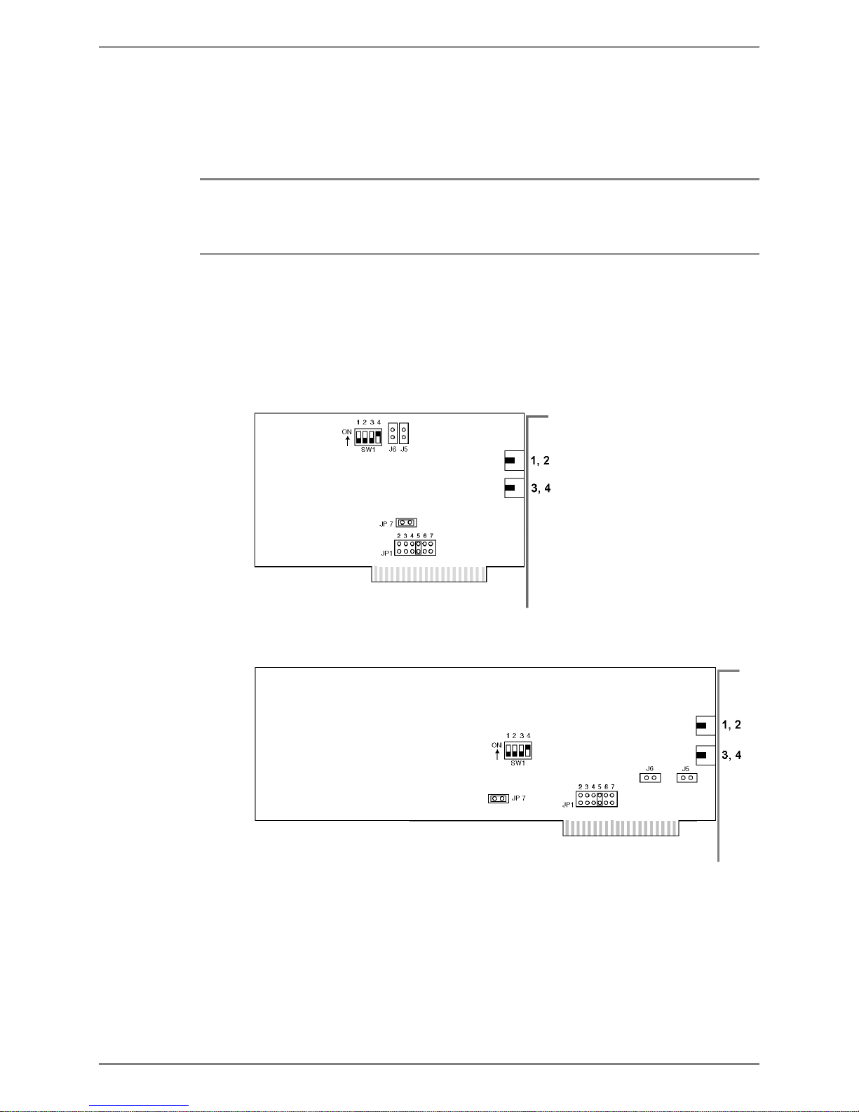
The following figure illustrates the DIALOG/4 board.
The following diagram illustrates the D/4xD board. The location of the relevant jumpers
and switches on the D/42D-SX board is approximately the same as on the D/4xD board.
Dialogic boards are all configured the same way for Octel 50. Complete the following
steps, as required, to configure each Dialogic board:
•
Set the board’s base shared memory address
•
Modify the board’s base memory segment
•
Set the board’s hardware interrupt
•
Set the default line state
Octel 50 Installation Guide
3-4
Installing the Hardware Step 3: Configuring the Voice Boards
•
Configure for multiple boards
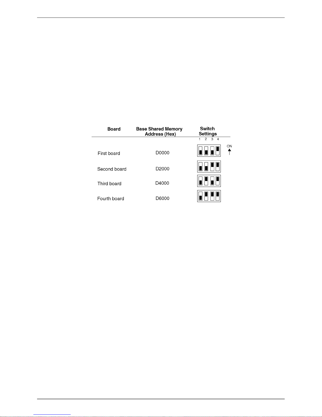
Setting the board’s base shared memory address–The base shared memory address
allows the voice board to communicate with the voice driver and, in turn, the Octel 50
system. SW1 determines the Dialogic board’s base shared memory address.
If you are only installing one Dialogic board, leave SW1 at the default setting unless it
conflicts with another component. If you are installing multiple boards or there is a conflict,
you can change the base shared memory address by configuring the first three jumpers
on SW1.
The following figure illustrates the recommended jumper settings for the boards. The first
column lists the board number, the second column lists the base shared memory address
that should be assigned to each board, and the third column represents the jumper
settings that correspond to the base shared memory address.
Modifying the board’s base memory segment–The shared memory block on the PC is
called a segment. You can set most Dialogic boards to an address in the D segment,
which is the default. If you cannot use the D segment due to a conflict or for some other
reason, a technical support representative can advise you to use an address in segment
A or C.
To use an alternate segment, you must install one of two jumpers on the Dialogic board:
•
Install the JP5 jumper if you assign the voice board an address using the A
segment, such as A0000.
•
Install the JP6 jumper if you assign the voice board an address using the C
segment, such as C0000.
Do not change the settings of either of these jumpers unless a technical support
representative directs you to set the voice board to an address using an alternate
segment.
Setting the board’s hardware interrupt–The JP1 jumper block sets the Dialogic boards’
hardware interrupt level, also called the IRQ. Interrupt settings for these boards range
from 2 through 7. Install the jumper that corresponds to the interrupt level you want to
use. You must set all Dialogic boards to the same interrupt level. The recommended
interrupt is IRQ5. Depending on the system configuration, you may have to try different
interrupts before you find one that does not conflict with other devices.
The interrupt levels typically assigned to standard computer components are as follows:
IRQ3 = COM2
IRQ4 = COM1
IRQ5 = LPT2
Octel 50 Installation Guide
3-5
Installing the Hardware Step 3: Configuring the Voice Boards
IRQ6 = disk drive
IRQ7 = LPT1
Setting the board’s default line state–The fourth jumper on SW1 determines whether
the lines connected to the voice board return a ring-no-answer signal or a busy signal
when the Octel 50 system is not running. Make sure this jumper is always on to indicate
that the lines should return a busy when the Octel 50 system is not running.
Configuring for multiple boards–If you are installing multiple Dialogic boards, remove
the JP7 jumper clip on all but the first board. If you are using a single board, leave the JP7
jumper clip installed.
Configuring Rhetorex Boards
Rhetorex 432, 4132 and 4108 boards are supported for existing systems in which they
are already installed.
All Rhetorex boards are configured the same way for Octel 50. All Rhetorex boards are
factory-set to a default address of 300 hex. If you are only installing one voice board,
leave the port address at the factory default unless it conflicts with the address of another
system component. If you are using multiple Rhetorex boards, you must assign a unique
port address to each board. Check with your PC manual to determine an available port
address.
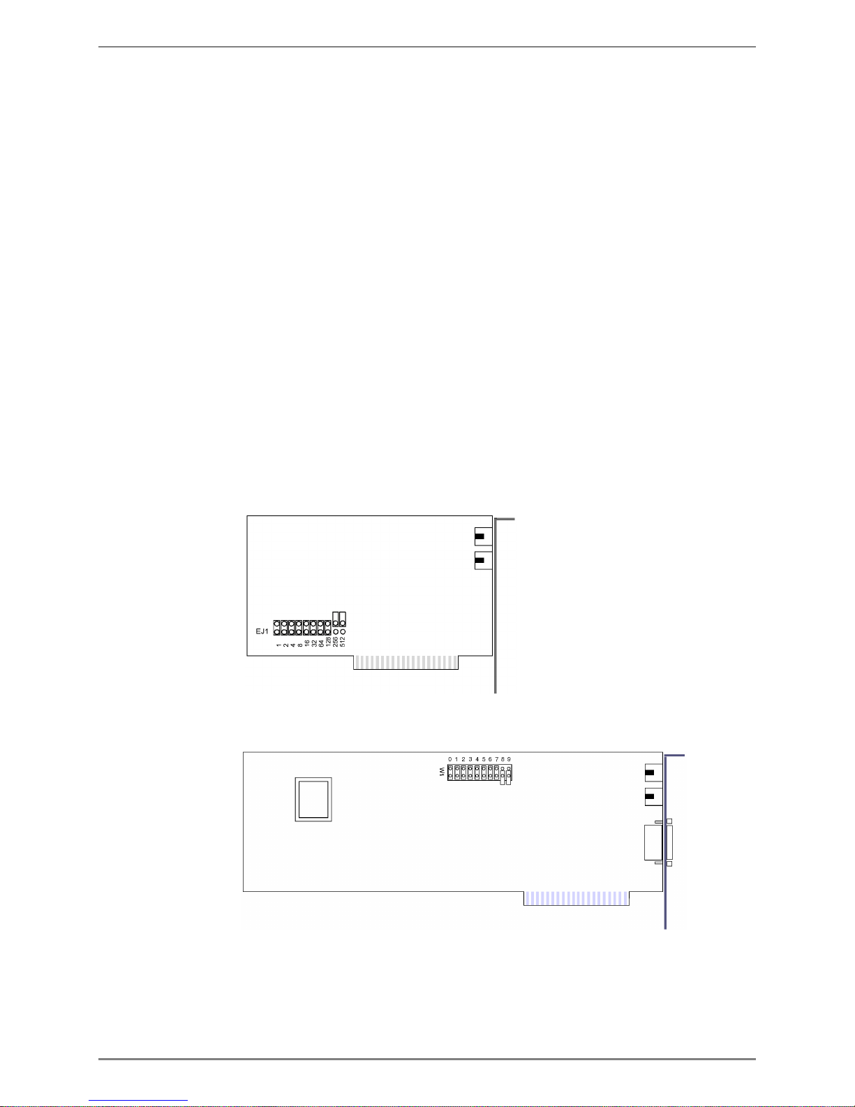
The following figure illustrates the default settings for the 432 board. On the 432 board,
the EJ1 jumper block sets the port address.
The following figure illustrates the default settings for the 4132 and 4108 boards. On the
432 board, the W1 jumper block sets the port address.
Octel 50 Installation Guide
3-6

Installing the Hardware Step 4: Configuring the Fax Boards
The following figure displays recommended jumper settings for the 432 board. The first
column lists the board number, the second column lists the port address that should be
assigned to each board, and the third column represents the jumper settings that
correspond to the port address.
The following figure displays recommended jumper settings for the 4132 and 4108
boards. The first column lists the board number, the second column lists the port address
that should be assigned to each board, and the third column represents the jumper
settings that correspond to the port address.
Step 4: Configuring the Fax Boards
Fax boards allow the Octel 50 system to use the Fax Solution features. You must
configure the fax boards for use with the Octel 50 system before you install them.
Fax boards contain ports, which are the interface between the fax board and a phone
system channel. The Octel 50 system supports a maximum of 12 fax channels.
Octel 50 supports the Brooktrout TR112 fax board.
The boards you install in the Octel 50 PC must be purchased from an authorized
representative so they are programmed with the proper signature.
Octel 50 Installation Guide
3-7

Installing the Hardware Step 4: Configuring the Fax Boards
Use caution when handling fax boards as they are electrostatic-sensitive. Make sure you
ground the PC, the work area, and the ground end of the antistatic wrist strap prior to
handling a board, and always use antistatic wrist straps and electrostatic-dissipative mats
while handling a board.
Configuring Brooktrout TR112 Boards
The TR112 is a 2-port fax card for use with the Fax Solution module.
Before installing the TR112 board, you must:
•
Set the board’s port address
•
Set the interrupt level
•
Set the DMA channel
Setting the TR112 Port Address
The PC and the Brooktrout boards communicate with each other through a shared
memory block that resides within the memory address space of the PC. You can modify
the physical address offset where this memory block is located by changing the dip
switches of SW1.
The default setting, 220, is acceptable for the first TR112 board. However, if you are
installing more than one TR112 board, the address must be changed as shown in the
following figure. The SW1 switch is located in the lower-right corner of the board and
contains eight dip switches.
Octel 50 Installation Guide
3-8
 Loading...