

Page 1

Managing Your Network Using the HTTP Server
BayRS Version 13.0 0
Site Manager Software Version 7.00
BCC Version 4.05
Part No. 303552-A Rev 00
October 1998
Page 2

4401 Great America Parkway 8 Federal Street
Santa Clara, CA 95054 Billerica, MA 01821
Copyright © 1998 Bay Netw ork s, Inc.
All rights reserved. Pr inted in the USA. October 1998.
The information in this document is subject to change without notice. The statements, confi gurations, technica l data,
and recomm endations in this docum ent are believed to be accurate and reliable, but are presented without express or
implied warranty. U sers must take full respons ibility for their applications of any products specified in this do cum ent.
The information in this document is proprietary to Bay Networks, Inc.
The software described in this document is furnished under a license agreement and may only be used in accordance
with the te rms of that license. A summary of the Soft w are License is include d in this docum ent.
Trademarks
AN, BCN, BLN, BN, FRE, Optivity, PPX , and Bay Networks are registered trademarks a nd A dvanced Remote No de,
ANH, ARN, ASN, BayRS, BaySecur e, BayStac k, BaySt ream, BCC, SP EX, Syst em 5000, and th e Bay Netw ork s logo
are trademarks of Bay Net w orks, Inc.
Microsoft , MS, MS-DOS, Win32, Windows, Inter net Explorer, and Windows NT are reg istered trademarks of
Microsoft Corporation.
All other trademarks and registered trademarks are the property of their respective owners .
Restricted Rights Legend
Use, duplication, or disclosure by the United States Government is subject to restrict ions as set forth in subparagraph
(c)(1)(ii) of the Rights in Technical Data and Computer Software clause at DFARS 252.227-7013.
Notwithstanding any other license agreement th at may pertain to, or accompany the delivery of, this computer
software, the ri ghts of the Un ited States Gove rnment re garding its use, reproduction, and disclosure are as set forth in
the Commercial Computer Software-Restricted Rights clause at FAR 52.227-19.
Statement of Conditions
In the interest of improving internal design, operational function, and/or reliability, Bay Networks, Inc. reserves the
right to make changes to the products described in this document without notice.
Bay Networks, Inc. does not assume an y liability that may occur due to the use or applic ation of the product(s) or
circuit layout(s) described herein.
Portions of the code in this software product may be Copyright © 1988, Regents of the University of California. All
rights reserve d. Redistribution and use in source and binary forms of such portions are permitted, provided that the
above copyright notice and this paragrap h are duplicated in all su ch forms and th at any docume ntation, adverti sing
materials, and other materials related to such distribution and use acknowledge that such portions of the software were
deve loped by th e U niversity of California, Berkeley. The nam e of the University may not be used to endorse or
promote products derived from such portions of the software without specific prior written permission.
SUCH PORTIONS OF THE SOFTWARE ARE PROVIDED “AS IS” AND WITHOUT ANY EXPRESS OR
IMPLIED WARRANTIES, INCLUDING, WITHOUT LIMITATION, THE IMPLIE D WARRANTIES OF
MERCHANTABILITY AND FITNESS FOR A PARTICULAR PURPOSE.
In additi on, the program and information contained herein are li censed only pursuant to a license agreement that
contains restrictions on use and disclosu re (that may incorporate by refer ence certain limitations and not ices imposed
by thir d pa rt ie s).
ii
303552-A Rev 00
Page 3

Bay Networks, Inc. Software License Agreement
NOTICE: Please carefully read this license agreement before copying or using the accompanying software or
instal ling the hardware unit with pre-enabled software (e ach of which is referred to as “Softw are” in this Agreement).
BY COPYING OR USING THE SOFTWARE, YOU ACCEPT ALL OF THE TERMS AND CONDITIONS OF
THIS LICENSE AGREEMENT. THE TERMS EXPRESSED IN THIS AGREEMENT ARE THE ONLY TERMS
UNDER WHICH BAY NETWORKS WILL PERMIT YOU TO USE THE SOFTWARE. If you do not accept these
terms and conditions, return the product, unused and in the o riginal shipping container, within 30 days of purchas e to
obtain a credit for the full purchase price.
1. License Grant. Bay Networks, Inc. (“Bay Networks”) gra nts the end user of the Software (“Lice nsee”) a personal,
nonexcl usive, nontransferable license: a) to use the Software either on a single computer or, if applic able, on a singl e
authori zed de vi ce ide ntified by host ID, fo r whi ch it was origi nal ly acq uired ; b) to cop y th e Softw ar e so le ly fo r bac kup
purposes in support of authorized us e of the Software; and c) to us e and copy the associated user manual solely in
support of authorized use of the Soft w are by Licensee. This li cense applies to the Software only and does not extend
to Bay Networks Agent software or other Bay Networks softw are products. Bay Networks Agent software or other
Bay Networks software products are licensed for use under the terms of the applicable Bay Networks, Inc. Software
License Agreement that accompanies such software and upon payment by the end user of the applicable licen se fees
for such software.
2. Restrictions on use; reservation of rights. The Software and user manuals are protect ed under copyright laws.
Bay Networks and/or its licensors retain all title and ownership in both the Sof tware and user manuals, including any
revis ions made by Bay Networks or its licensors. The copyright notice must be reproduced and included wi th any
copy of any por tion of the Sof tw are or use r manua ls . Licens ee may not modif y, translate, dec ompi le , disas se mble , use
for any compe ti ti v e an al ysis, r e v erse e ngi ne er , dis tr ib ute , o r c rea te der i vative work s f ro m the Softw are or u se r man ual s
or any copy, in whole or in part. Except as expressly provided in this Agreement, Licensee may not copy or transfer
the Softw are or user man uals, in whole or in part. Th e Software and user manuals embody Bay Networks’ and it s
licenso rs’ confidential and proprietary intell ectual property. Licensee shall not sublicense, assign , or otherwise
disclos e to any third party the Software, or any information about the operation, design, performance, or
implementation of the Software and user manuals that is confidential to Bay Networ ks and its licensors; however,
Licensee m ay grant permission to its consul tants, subcontractors, and agents to use the Software at Licensee’ s facility,
provided they have agreed to use the Software only in accordance with the terms of th is license.
3. Limited warranty. Bay Networks warrants each item of Software, as delivered by Bay Network s and properly
installed and operated on Bay Networks hardware or other equipment it is originally licensed for, to function
substantially as described in i ts accompanying user manual during its warranty period, wh ich begins on the date
Softwar e is fi r st shi pped to Licen see . If any it em of Soft war e fai ls to so func ti on du ring i ts warr anty pe ri od, as t he so le
remedy Bay Ne tworks will at its discretion provide a suitable fix, pat ch, or workaround for the problem tha t m ay be
included in a future Software release. Bay Networks further warrants to Licensee that the media on which the
Softwar e is provided will be fr ee from defects in materials and workmanship under normal use for a period of 90 days
from the date Software is first shipped to Licensee. Bay Networks will replace defective media at no charge if it is
returned to Bay Netw orks during the warranty per iod along with proof of the date of shipmen t. This warran ty does not
apply i f the media has been damaged as a result of acci dent, misuse, or abuse. The Licensee assumes all re sponsibility
for selection of the Software to achieve Licensee’s intended results and for the installation, use, and results obtained
from the Software. Bay Networks does not warrant a) that the functions cont ained in the software w ill meet the
Licensee ’s requirements, b) that the Software will operate in the har dw are or software combinations that the Licensee
may select, c) that th e operation of the Software will be uninterrupted or error free, or d) that all defects in the
operati on of the Software wi ll be corrected. Bay Networks is not ob ligated to remedy any Software defect that cannot
be repro duced with the latest Software release. Thes e warranties do not apply to the Sof tware if it has been (i) altered,
except by Bay Networks or in accordance with its instructions; (ii) used in conjunction with another vendor’s product,
resulting in the defect; or (iii) damaged by im proper environm ent, abuse, misuse, accident, or neglige nce. THE
FOREGOING WARRANTIES AND LIMITATIONS ARE EXCLUSIVE REMEDIES AND ARE IN LIEU OF ALL
OTHER WARRANTIES EXPRESS OR IMPLIED, INCLUDING WITHOUT LIMITATION ANY WARRANTY OF
MERCHANTABILITY OR FITNESS FOR A PARTICULAR PURPOSE. Licensee is responsible for the security of
303552-A Rev 00
iii
Page 4

its own data and information and for maint aining adequate procedures apart from the Software to reconstruct lost or
altered files, data, or programs.
4. Limitati on of liabili ty. IN NO EVENT WILL BAY NETWORKS OR ITS LICENSORS BE LIABLE FOR ANY
COST OF SUBSTITUTE PROCUREMENT; SPECIAL, INDIRECT, INCIDENTAL, OR CONSEQUENTIAL
DAMAGES ; OR ANY DAMAGES RESULTING FROM INACCURATE OR LOST DAT A OR LOSS OF USE OR
PROFITS ARISING OUT OF OR IN CONNECTION WITH THE PERFORMANCE OF THE SOFTWARE, EVEN
IF BAY NETWORKS HAS BEEN ADVISED OF THE POSSIBILITY OF SUCH DAMAGES. IN NO EVENT
SHALL THE LIABILITY OF BAY NETWORKS RELATING TO THE SOFTWARE OR THIS AGREEMENT
EXCEED THE PRICE PAID TO BAY NETW ORKS FOR THE SOFTWARE LICENSE.
5. Governmen t L i c en s ees. This provisio n applies to all Software and documentation acquired directly or indirectly
by or on behalf of the United States Government. The Software and documentation are commercial products, licensed
on the open market at market prices, and were developed entirely at private expense and without the use of any U.S.
Government funds. The license to the U.S. Government is granted only with restricte d rights, and use, duplication, or
disclos ure by the U.S. Gover n m ent is subject to the restrictions set forth in subparagraph (c)(1) of the Commercial
Computer So ftware––Restricted Rights clause of FAR 52.227-19 and the limitations set out in this license for civilian
agencies , and subparagraph (c) (1)(ii) of the Rights in Technical Data and Computer Software clause of DFARS
252.227-7013, for agencies of t he D e partment of Defense or their suc cessors, whiche ver is applicable.
6. Use of Software in the European Communi ty. This prov ision applies to all Software acquired for use within the
European Comm unity. If Lice nsee uses the Software within a countr y in the European Community, the Softwar e
Directive enacted by the Counc il of European Communities Directive dated 14 May, 1991, w ill apply to the
examination of the Software to facilitate interoperability. License e agrees to notify Bay Networks of any such
intended examination of the Software and may procure support and assistance from Bay Networ ks.
7. Term and termination. This license is effective until terminated; however, all of the restrictions with respect to
Bay Networks’ copyright in the Software and user manuals will cease being effective at the date of expiration of the
Bay Networks copyright; those r estrictions relating to use and disclosure of Bay N etworks’ confidential information
shall continue in effect. Licensee may terminate this license at any time. The license will automatically terminate if
Licensee fails to co m ply with any of the terms and conditions of the license. Upon terminat ion for any reason,
Licensee will immediately destroy or return to Bay Networks the Software, user manuals, and all copies. Bay
Networks is not liable to Licensee for damages in any form solely by reason of the termination of this license.
8. Export and Re-export. Licensee agrees not to export, direct ly or indirectly, the Software or related technical data
or information without first obtaining any required export licenses or other governmental approvals. Without limiting
the fore going, Licensee, on behalf of itself and its subsidiaries and affiliates, agrees that i t will not, without first
obtaining all export licenses and appro vals required by the U.S. Government: (i) export , re-export, transfer, or diver t
any such Sof tware or technical data, or any direct product thereof, to any coun try to which such exports or re-exports
are rest ricted or embargoed under United States ex port control laws a nd regulations, or to any national or resident of
such rest ricted or embargoed countries; or (ii) provide the Software or related technical data or inf ormation to any
military end user or for any military end use, including the design, develop ment, or production of any chemical,
nuclear, or biological weapons.
9. General. If any provision of this Agreement is held to be invalid or unenforceable by a court of competent
jurisdiction, the remainder of the provisions of this Agreement shall remain in full force and effect. This Agreement
will be governed by the laws of the state of California.
Should you have any questions concerning this Agreement, contact Bay Networks, Inc., 440 1 G reat America
Parkway, P.O. Box 58185, Santa Clara, Californi a 95054-8185.
LICENSEE ACKNOW LEDGES THAT LICENSEE HAS READ THIS AGREEMENT, UNDERSTANDS IT, AND
AGREES TO BE BOUND BY ITS TERMS AND CONDITIONS. LICENSEE FUR THER AGREES THAT THIS
AGREEMENT IS THE ENTIRE AND EXCLUSIVE AGREEMENT BETWEEN BAY NETWORKS AND
LICENSEE, WHICH SUPERSEDES ALL PRIOR ORAL AND WRITTEN AGREEMENTS AND
COMMUNICATIONS BETWEEN THE PARTIES PERTAINING TO THE SUBJECT MATTER OF THIS
AGREEMENT. NO DIFFERENT OR ADDITIONAL TERMS WILL BE ENFORCEABLE AGAINST BAY
NETWORKS UNLESS BAY NETWORKS GIVES ITS EXPRESS WRITTEN CONSENT , INCLUDING AN
EXPRESS WAIVER OF THE TERMS OF THIS AGREEMENT.
iv
303552-A Rev 00
Page 5

Contents
Preface
Before You Begin ............................................................................................................xvii
Text Conventions ................................................................... ........................................xviii
Acronyms .........................................................................................................................x ix
Bay Networks Technical Publications ..............................................................................xx
How to Get Help ..............................................................................................................xxi
Chapter 1
Sta rtin g th e HTT P Server
Browser Requ i r e men ts ...................... ....................................................................... ......1-2
Starting the HTTP Server Using install.bat .....................................................................1-2
Starting the HTTP Server Using the BCC or Site Manager ............................................1-3
Chapter 2
HTTP Server Concepts
What the HTTP Server Does .......................................................................................... 2-1
Navigating the HTTP Server Interface ............................................................................2-3
Chapter 3
HTTP Server Security
User Name/Password Security .......................................................................................3-1
Network Address Filtering ..............................................................................................3-2
Chapter 4
Using the HTTP Server
Getting Help ....................................................................................................................4-1
Specifyin g a Device ...................................................................................... ..................4-2
Viewing Overall System Status .......................................................................................4-3
Viewing Hardware Summary Infor mation .................................................................4-5
Viewing PROM Summary Information .....................................................................4-6
Viewing Software Image Summary Information .......................................................4-7
303552-A Rev 00
v
Page 6

Viewing System Resource Summary Information ....................................................4-8
Viewing System Task Summary Information ............................................................4-9
Chapter 5
Viewing Circuit Alerts and Events
Displaying Circuit Alerts ..................................................................................................5-2
Viewing the Event Log ....................................................................................................5-2
Specifying the Contents of the Event Log Display .. .................................................5-3
Interpreting Event Messages ...................................................................... ....... ......5-4
Chapter 6
Viewing Router Service Statistics
Viewing TFTP Statistics ..................................................................................................6-2
Viewi ng TCP Statistics ........................................................................................... ........6-3
Viewing FTP Statistics ....................................................................................................6-4
Viewing Telnet Statistics ................................................................................................. 6-4
Viewi ng Bo o tP Sta tistics ...... ....................................................................... ....................6-5
Viewi ng Bo o tP Traffic Statistics ................................................................................6-5
Viewing BootP Interface Statistics ............................................................................6-5
Viewi ng Bo o tP Cli e n t Sta tistics ... ......................................................... ....................6-6
Viewing BootP Preferred Server Statistics ...............................................................6-6
Viewing BootP Relay Agent Statistics ...................................... ....... ....... ..... ....... ......6-7
Viewi ng SNMP Statistics ....... ........................................... ..............................................6-7
Viewing SNMP Counter Statistics ............................................................................ 6-8
Viewing SNMP Community Statistics .......................................................................6-8
Viewing SNMP Entity Trap Statistics ........................................................................6-9
Viewing SNMP Exception Statistics .......................................................................6-10
Viewing HTTP Statistics ............................................................................................... 6 -10
Viewing HTTP Server Configuration Statistics .......................................................6-11
Viewing HTTP Counter Summary Statistics ........................................... .......... ......6-12
Viewing HTTP Request Statistics ....................... .. ....... .......... ....... .. ....... .......... .. ....6-13
Viewing HTTP Response Statistics ........................................................................6-14
vi
303552-A Rev 00
Page 7

Chapter 7
Viewing Router Port Statistics
Changing the Administrative Status of a Port ................................................................. 7-2
Viewi ng Traffic Statistics for All Ports ........... ............................ .......................................7-2
Viewing Ethernet Port Statistics ..................................................................................... 7-3
Viewi ng Eth e rnet Su mmary Statistics .......................... ............................................7-4
Viewi ng Eth e rnet Tra ffi c Sta tistics ............................................................................7-4
Viewi ng Eth e rnet Rec eive Error Statistics ............................................................. ...7-5
Viewing Ethernet Transmit Error Statistics ...............................................................7-5
Viewing Synchronous (Sync) Port Statistics ................................................................... 7-6
Viewing Synchronous Summary Statistics ...............................................................7-6
Viewing Synchronous Traffic Statistics .....................................................................7-7
Viewing Synchronous Receive Error Statistics ........................................................7-7
Viewing Synchronous Transmit Error Statistics ........................................................7-8
Viewing Synchronous System Error Statistics .........................................................7-8
Viewing FDDI Por t Statistics ...........................................................................................7-9
Viewing FDDI Summary Statistics ...........................................................................7-9
Viewing FDDI Traffic Statistics ...............................................................................7-10
Viewing FDDI Receive Error Statistics ...................................................................7-10
Viewing FDDI Transmit Error Statistics ..................................................................7 -11
Viewing FDDI System Error Statistics ....................................................................7-11
Viewing HSSI Port Statistics .........................................................................................7-12
Viewing HSSI Summary Statistics ......................................................................... 7 -12
Viewing HSSI Traffic Statistics ...............................................................................7-13
Viewing HSSI Receive Error Statistics ...................................................................7-13
Viewi ng HSSI Tran s mi t Err o r Sta tistics ..... ........................................... ..................7-14
Viewing HSSI System Error Statistics ....................................................................7-14
Viewing Token Ring Port Statistics ...............................................................................7 -15
Viewing Token Ring Summary Statistics ................................................................7-15
Viewing Token Ring Traffic Statistics ......................................................................7-16
Viewing Token Ring Receive Error Sta tistics .........................................................7-16
Viewing Token Ring Transmit Error Statistics .........................................................7-17
Viewing Token Ring System Error Statistics ..........................................................7-17
303552-A Rev 00
vii
Page 8

Chapter 8
Viewing Rout er P rotoc ol Stat i s tics
Changing the Administrative Status of a Port ................................................................. 8-2
Viewi ng IP Sta tistics ....... ......................................................... .......................................8-2
Viewi ng IP Su mmary Stat istics ................................................................................8-3
Viewi ng IP Traffic Statistics .............................................................................. ........8-4
Viewing IP Interface Statistics ..................................................................................8-5
Viewing IP Route Statistics ......................................................................................8-6
Viewi ng IP ARP Cac he Sta tistics ....... ............... .......................................................8-7
Viewing IP RIP Interface Statistics ........................................................................... 8-8
Viewing IP ICMP Statistics .......................................................................................8-8
Viewing ICMP Counter Statistics .............................................................................8-9
Viewing ICMP Received Statistics .........................................................................8-10
Viewing ICMP Transmitted Statistics ...................................................................... 8 -11
Viewing IPX Statistics ...................................................................................................8-11
Viewing IPX Summary Statistics ............................................................................8-12
Viewing IPX Traffic Statistics ..................................................................................8-13
Viewing IPX Interface Statistics ..............................................................................8-13
Viewing IPX Forwarding Statistics ..........................................................................8-14
Viewing IPX Host Statistics ....................................................................................8 -14
Viewing IPX Route Statistics ..................................................................................8-15
Viewing IPX Service Statistics ...............................................................................8 -15
Viewing IPX RIP Interface Statistics .......................................................................8-16
Viewing IPX SAP Statistics .................................................................................... 8 -16
Viewing AppleTalk Statistics .........................................................................................8-17
Viewing AppleTalk Summary Statistics ..................................................................8-17
Viewing AppleTalk Traffic Statistics ........................................................................8-18
Viewing AppleTalk Interface Statistics ....................................................................8-18
Viewing AppleTalk Route Statistics ........................................................................8-19
Viewing AppleTalk ARP Cache Statistics ...............................................................8 -19
Viewing AppleTalk Zone Statistics ......................................................................... 8 -20
viii
303552-A Rev 00
Page 9

Chapter 9
Customizing HTTP Server Parameters
Disabling and Reenabling the HTTP Server ................................................................... 9-2
Specifying the Port Number for the HTTP Server ...........................................................9-3
Specifying the Maximum Number of Cached Archives ...................................................9-4
Specifying the Maximum Time of Cached Archives .......................................................9-5
Appendix A
Site Manag er Param et ers
Appendix B
Viewing HTTP Server Statistics Using the Statistics Manager
Selecting the Screens to Display ........................................ .......... ....... .. ....... .......... .......B-2
Star ti n g the Statistic s Lau n c h Facility ............... . .. ... .. .... . .. .... . .. ... .. .. ... .. .. ... .. .. ... .. ............. B-3
Viewing HTTP Request Statistics ...................................................................... ....... .....B-4
Viewing HTTP Response Statistics ............................................................................... B-5
Viewing HTTP Server Configuration Statistics .............................................................. B-6
Viewing HTTP Summary Statistics ................................................................................B-7
Index
303552-A Rev 00
ix
Page 10

Page 11

Figures
Figure 2-1. Initial HTTP Server Window .....................................................................2-2
Figure 2-2. Navigational Frame .......................................................................... ....... .2-4
Figure 4-1. Initial HTTP Server Window .....................................................................4-3
Figure 4-2. System Inform ation Summary .................................................................4-4
Figure 4-3. Hardware Information Summary .............................................................. 4-5
Figure 4-4. PROM Information Summary ...................................................................4-6
Figure 4-5. Software Image Information Summary ....................................................4-7
Figure 4-6. System Resource Summary .................................................................... 4-8
Figure 4-7. System Task Summary ............................................................................4-9
Figure 5-1. Circuit Alert Display .................................................................................5-2
Figure 5-2. Event Log Dis play ............ .............. ..........................................................5-3
Figure 6-1. TFTP Statistics .........................................................................................6-2
Figure 6-2. TCP Statisti cs ............................................................. .............................6-3
Figure 6-3. FTP Statistics ...........................................................................................6-4
Figure 6-4. Telnet Statistics ........................................................................................ 6-4
Figure 6-5. BootP Traffic Statistics ................... ..........................................................6-5
Figure 6-6. BootP Relay Agent Interface Statistics ....................................... ....... ..... .6-6
Figure 6-7. BootP Client Statistics ..............................................................................6-6
Figure 6-8. BootP Preferred Server Statistics ............................................................6-7
Figure 6-9. BootP Relay Agent Statistics ....................... .......... .. ....... ....... .......... .. ......6-7
Figure 6-10. SNMP Counter Statistics ......................................................................... 6-8
Figure 6-11. SNMP Community Statistics ....................................................................6-9
Figure 6-12. SNMP Entity Trap Statistics .....................................................................6-9
Figure 6-13. SNMP Exception Statistics ....................................................................6-10
Figure 6-14. HTTP Server Configuration Statistics ....................................................6-11
Figure 6-15. HTTP Summary Statistics ......................................................................6 -12
Figure 6-16. HTTP Request Statistics ........................................................................6-13
Figure 6-17. HTTP Response Statistics .....................................................................6-14
Figure 7-1. Port Traffic Statistics ................................................................................7-3
303552-A Rev 00
xi
Page 12

Figure 7-2. Ethernet Summary Statis ti cs .... ...............................................................7-4
Figure 7-3. Ethernet Traffic Statistics ... ......................................................... .............7-4
Figure 7-4. Ethernet Receive Er r o r Sta tistics .............................................................7-5
Figure 7-5. Ethernet Transmit Error Statistics ............................................................7-5
Figure 7-6. Synchronous Summary S tatistics ............................................................7-6
Figure 7-7. Synchronous Traffic Statistics ..................................................................7-7
Figure 7-8. Synchronous Receive Error Statistics ...................................................... 7-7
Figure 7-9. Synchronous Transmit Error Statistics .....................................................7-8
Figure 7-10. Synchronous System Error Statistics .......................................................7-8
Figure 7-11. FDDI Summary Statistics .........................................................................7-9
Figure 7-12. FDDI Traffic Statistics .............................................................................7-10
Figure 7-13. FDDI Receive Error Statistics ................................................................7-10
Figure 7-14. FDDI Transmit Error Statistics ................................................................7-11
Figure 7-15. FDDI System Error Statistics .................................................................7-11
Figure 7-16. HSSI Summary Statistics .......................................................................7-12
Figure 7-17. HSSI Traffic Statistics .............................................................................7-13
Figure 7-18. HSSI Receive Error Statistics ................................................................7-13
Figure 7-19. HSSI Transmit Error Statistics ................................................................7-14
Figure 7-20. HSSI System Error Statistics .................................................................7-14
Figure 7-21. Token Ring Summary Statistics .............................................................7-15
Figure 7-22. Token Ring Traffic Statistics ...................................................................7-16
Figure 7-23. Token Ring Receive Error Statistics .......................................................7-16
Figure 7-24. Token Ring Transmit Error Statistics ...................................................... 7-17
Figure 7-25. Token Ring System Error Statistics ........................................................7-17
Figure 8-1. IP Summary Statistics .................. ............................................................8-3
Figure 8-2. IP Traffic Statistics ....................................................................................8-4
Figure 8-3. IP Interface Statistics ...............................................................................8-5
Figure 8-4. IP Route Statistics ....................................................................................8-6
Figure 8-5. IP ARP Cache Statistics ..........................................................................8-7
Figure 8-6. IP RIP Interface Statistics ........................................................................8-8
Figure 8-7. ICMP Counter Statistics ........................................................................... 8-9
Figure 8-8. ICMP Received Statistics .......................................................................8-10
Figure 8-9. ICMP Transmitted Statistics ................................................................... 8 -11
Figure 8-10. IPX Summary Statistics ......................................................................... 8 -12
Figure 8-11. IPX Traffic Statistics ...............................................................................8-13
xii
303552-A Rev 00
Page 13

Figure 8-12. IPX Interface Statistics ...........................................................................8-13
Figure 8-13. IPX Forwarding Statistics .......................................................................8-14
Figure 8-14. IPX Host Statistics ................................................................................. 8 -14
Figure 8-15. IPX Route Statistics ...............................................................................8-15
Figure 8-16. IPX Service Statistics .............................................................................8-15
Figure 8-17. IPX RIP Interface Statistics ....................................................................8-16
Figure 8-18. IPX SAP Interface Statistics ...................................................................8-16
Figure 8-19. AppleTalk Summary Statistics ...............................................................8-17
Figure 8-20. AppleTalk Traffic Statistics .....................................................................8-18
Figure 8-21. AppleTalk Interface Statistics .................................................................8-18
Figure 8-22. AppleTalk Route Statistics .....................................................................8-19
Figure 8-23. AppleTalk ARP Table Statistics ..............................................................8-19
Figure 8-24. AppleTalk Zone Statistics .......................................................................8-20
Figure A-1. Edit HTTP Global Parameters Window ...................................................A-2
Figure B-1. Statistics Manager Window .................................................. ....... ....... .....B-2
Figure B-2. Statistics Launch Facility Window ...................................................... .....B-3
Figure B-3. HTTP Request Statistics Window .......................................... .......... .. .....B-4
Figure B-4. HTTP Response Statistics Window ........................................................ B-5
Figure B-5. HTTP Server Configuration Window .......................................................B-6
Figure B-6. HTTP Summary Statistics Window .........................................................B-7
303552-A Rev 00
xiii
Page 14

Page 15

Tables
Table 5-1. Event Message Severity Levels .................................................. ....... ......5-4
303552-A Rev 00
xv
Page 16

Page 17

Preface
This guide describes the
do to start and customize the HTTP Serv er on a Bay Networks® router.
You can use the Bay Command Console (BCC
HTTP Server on a router. In this guide, you will find instructions for using both
the BCC and Site Manager .
Before You Begin
Before using this guide, you must complete the following procedure s. For a new
router:
• Install the router (see the inst allation guide that came with your router).
• Connect the router to the network and create a pilot configuration file (see
Quick-Starting Routers, Configuring BayStack Remote Access, or Connecti ng
ASN Routers to a Network).
Make sure tha t you are running the latest version of Bay Networks BayRS
Site Manager software. For information about upgrading BayRS and Site
Manager, see the upgr ading guide for your version of B ayRS.
Hypertext Transfer Protocol (
™
) or Site Manager to conf igure the
HTTP) Server and what you
™
and
303552-A Rev 00
xvii
Page 18

Managing Your Network Using the HTTP Server
Text Conventions
This guide use s the following text conventions:
angle brackets (< >) Indicate that you choose the text to enter based on the
description inside the brackets. Do not type the
brackets when entering the command.
Example: If the command syntax is:
bold text
<ip_address>
ping
ping 192.32.10.12
Indicates text tha t you need to enter and command
, you enter:
names and options.
Example: Enter
Example: Use the
show ip {alerts | routes
command.
dinfo
}
braces ({}) Indicate required elements in syntax descriptions
where there is more than one option. You must choose
only one of the options. Do not type the braces when
entering the command.
Example: If the command syntax is:
, you must enter either:
show ip {alerts | routes
show ip alerts or show ip routes
}
.
brackets ([ ]) Indicate optional elements in syntax descriptions. Do
not type the brackets when entering the command.
Example: If the command syntax is:
, you can enter either:
show ip interfaces [-alerts
show ip interfaces
or
]
show ip interfaces -alerts
.
xviii
303552-A Re v 00
Page 19

Preface
italic text Indicates file and directory names, new terms, book
titles, and variables in command syntax descriptions.
Where a variable is two or more words, the words are
connected by an underscore.
Example: If the command syntax is:
<
show at
valid_route
valid_route>
is one va riable and you subs titu te one value
for it.
screen text Indicates system output , fo r exa mple, prompts and
system messages.
Example:
Set Ba y Netw orks Tr ap Mo nito r Fil ters
separator ( > ) Shows menu paths.
Example: Protocol s > IP identifies the IP option on the
Protocols menu.
|
vertical line (
) Separates choices for command keywords and
arguments. Enter only one of the choices. Do not type
the vertical line when entering the command.
Example: If the command syntax is:
Acronyms
303552-A Rev 00
, you enter either:
show ip {alerts | rou tes
show ip alerts
or
}
show ip routes
ARP Address Resolutio n Protocol
BootP Bootstrap Protoco l
FDDI Fiber Distributed Data Interface
FTP File Tra nsfer Protocol
GUI graphical user interface
HSSI High-Speed Ser ia l Interface
HTTP Hypertext T ransfer Protocol
ICMP Internet Control Message Protocol
IP Internet Protocol
, but not both.
xix
Page 20

Managing Your Network Using the HTTP Server
IPX Internetwor k Packet Excha n ge
ISO Int ernational Organiz ation for Standardization
LAN local area networ k
MAC media access control
MIB management information base
MTU maximum transmission unit
OSPF O pen Shor te st Path Fi rst
PPP Point-to-Point Protocol
PROM programmable read-only memory
RIP Routing Information Protocol
SAP Service Advertising Protocol
SNMP Simple Network Management Protocol
TCP Tra nsmission Control Protocol
TFTP Trivial File Transfer Protocol
WAN wide area network
Bay Netwo rks Technical Publicati o ns
You can now print Bay Networks technical manuals and release notes free,
directly from the Int ernet. Go to support.bayn etworks.com/libr ary/tpubs/. Fi nd the
Bay Networks product for which you need doc umenta tion. Then locate the
specific category and model or version for your hardwa re or software product.
Using Adobe Acrobat Reader, you can open the manuals and release notes, search
for the sections you need, and print them on most standard printers. You can
download Acrobat Reader free from the Adobe Systems Web site,
www.adobe.com.
xx
303552-A Re v 00
Page 21

You can purchase Bay Networks documentation sets, CDs, and selected technic al
publications through the Bay Networks Collateral Catalog. The catalog is located
on the World Wide Web at support.baynetworks.c om/catalog. html and is divided
into sections arran ged alpha betically:
• The “ CD ROMs” section lists available CDs.
• The “Guides/Books” section lists books on te chnical topics.
• The “Technical Manuals” section li sts available printed documentation set s.
Make a note of the part num bers and prices of the items that you want to order.
Use the “Marketing Collateral Catalog description” link to place an order and to
print the order form.
How to Get Help
For product assista nce, support contracts, or information about educational
services, go to the following URL:
http://www.baynetworks.com/corporate/contacts/
Preface
303552-A Rev 00
Or telephone the Bay Networks Technical Solutions Center at:
800-2LANWAN
xxi
Page 22

Page 23

Chapter 1
Starting the HTTP Server
The Bay Networks® HTTP Server is an embedded Web-based device
management tool accessible from a ny standard W eb browser. The HTTP Server is
included with the Bay Networks router operating system software . Using HTTP
Server softw are, you can monitor network devi ces, viewing summary, fault, and
statistical inf ormation on a device-by-device basis.
Before you can use the HTTP Server to monitor a router, you must ensure that
your browser is at the corr ect version and that its setti ngs are appropriate to
support the HTTP Server softwa re. You must also configure and enable the HTTP
Server softw are on the router using the Quick-Start installation script install.bat,
Site Manager, or the Bay Command Console (BCC
™
).
This chapter describes how you do each of these tasks.
Topic Page
Browser Requiremen ts
Starting the HTTP Server Using install.bat 1-2
Starting the HTTP Server Using the BCC or Site Manager 1-3
303552-A Rev 00 1-1
1-2
Page 24
Managing Your Network Using the HTTP Server
Browser Requirements
The HTTP Server softwar e requires a Web browser that suppor ts frames, such as
Netscape 3.0 or higher and Microsoft® Internet Expl orer® 3.0 or higher. You can
use the default se ttings f or thes e browse rs. If you hav e change d these set tings, you
must ensure that Java is enabled.
Internet Explorer all ows you to store your browser password. For
Note:
security reasons , it is wise not to store your password.
Starting the HTTP Server Using
A new router comes with a flash memory card containing the software image for
the router , two configuration files (conf ig and ti.cfg), and the Quick-Start scrip t
install.bat.
The Quick-Start installation script creates an initial IP network int erface on the
router, so that your router can communicate with the configuration workstation
from which you will manage the rout er. The install.bat script prompt s you to ent er
the network information that dynamically configur es the initial IP interface.
As the following exa mple shows, step 7 of the script asks whether you want to
enable HTTP. Answer yes to this question. (The default is no.)
Step 7. Enable HTTP
Enable the HTTP (Web) Server
----------------------------
Do you want to enable the HTTP (Web) server? (y/n)[n]:
HTTP server en abled.
For complete instructions on running the install.bat scrip t and verifying
Note:
that the installation is successful, see Quick-Starting Routers.
install.bat
y
1-2 303552-A Rev 00
Page 25

p
p
Starting the HTTP Server
When you enable the HTTP Server during the Quick-St art procedure , you can use
the HTTP Server after completing the install.bat proc edure . I f necessary, you can
modify the default HTTP Serv e r settings (see Chapter 9, “Customizing HTTP
Server Parameters).
After you run the install. bat script, you can install Site Manager software, as
described in Quick-Starting Routers.
Starting the HTTP Server Using the BCC or Site Manager
If you did not use the Quick-Start procedure to start the HTTP Server, you can
start it using the BCC or Site Manager. Before you start the HTTP Server, verify
that you configured IP on an interface.
You can start the HTTP Server using defa ult values for all parameters. If you
decide to change any of the default value s, see Chapter 9, “Customizing HTTP
Server Parameters.”
Using the BCC
Adding the HTTP Server to a router automatically loads TCP on all slots. To add
the HTTP Server to a router, navigate to the box prompt and enter:
htt
For example, the following command adds HTTP Server to a router:
box#
htt
http#
303552-A Rev 00 1-3
Page 26

Managing Your Network Using the HTTP Server
Using Site Manager
You can configure HTTP Serve r sof tware in an y Conf igur ation Manager m ode. To
start HTTP Server software, complete the following tasks:
Site Manager Procedure
You do this System responds
1. In the Configuration M anager window,
Protocols
choose
2. Choose
3. Choose
4. Choose
5. Choose
6. Choose
7. Choose
8. Choose
Global Protocols
TCP
Create TCP
Protocols
Global Protocols
HTTP
Create HTTP
.
. The Global Protocols menu opens.
. The TCP menu opens.
. You return to the Configuration Manager
. The Protocols menu opens.
. The Global Protocols menu opens.
. The HTTP menu opens.
. You return to the Configuration Manager
The Protocols menu opens.
window.
window.
When you complete this procedure, the HTTP Server softwa re is configured on
the router.
1-4 303552-A Rev 00
Page 27

Chapter 2
HTTP Server Concepts
With HTTP Server sof twar e, you can acce ss de vice inform ation f rom anywher e in
the network using an y stan dard Web browser that conform s to HTTP and HTML
specific ations. The HTTP Server is part of the router operating system for all Bay
Networks non-VME-based GAME routers. This chapter provides an overview of
the HTTP Server.
Topic Page
What the HTTP Server Does
Navigating the HTTP Server Int erface 2-3
To obtain Web-acc es sible data, you must configur e the embed ded HTTP Serv er
software on the router. Chapt er 1, “
configura tion procedure.
What the HTTP Server Does
The HTTP Server is a graphical user inte rface (GUI) that lets you vie w real -time
device sum maries, events, alerts, and statistics. The HTTP Server graphically
displays information similar to (and a subset of) the text- only information
ava ilable through the BCC
point-and-cli ck interf ace, you a lso ha v e direct acc ess to online doc umentati on and
Bay Networks Technical Support.
Starting the HTTP Server,” summarizes the
show, enable
, and
disable
2-1
commands. Through this
303552-A Rev 00 2-1
Page 28
Managing Your Network Using the HTTP Server
The information that you gathe r through the HTTP Server interface can help you
monitor your net work’s performance on a de vice -by- de vice basis. You can see, for
example, where conges tion is occurring or where transmission or reception
problems exist . F or detailed information a bout interpreting this inf ormation, refer
to Troubleshooting Routers and Event Messages for Routers.
Banner
frame
Navigational
frame
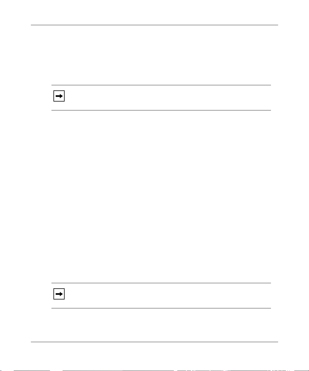
Figure 2-1
is an example of the HTTP Server interface viewed with the Netscape
Navigato r 3. 01 browser.
Note:
The examples in this book were gene rate d using Netscape Navigator
3.01, but you can use any standards-compliant We b browser with the HTTP
Server. You must use a browser that supports the use of frames.
Display
frame
Figure 2-1. Initial HTTP Server Window
2-2 303552-A Rev 00
Page 29

HTTP Server Concepts
This is the first window you see when you specify a device or when you click on
the Summary folder ic on, then on the Info icon in the navigational frame. The top
frame is the banner; it shows the Bay Networks logo and the device type. The
banner also identifies the device by name, specifies its physical location and IP
address, and lists the name of the contact person responsible for that device. The
IP address is a link that you can click on to establish a Tel net connection to the
device.
The first three rows of the display frame (System Infor mation) repeat the device
name, location, and contac t inf ormation. This frame also provide s the following
information:
• Up Time -- time elapsed since the last device reset
• MIB Version -- version num ber of the management information base ( MIB)
for the router sof twar e
• Software Version -- version number and creation date and time of the router
software image
The navigational frame contains links to each monitored function. Initially, these
links are all folders.
Navigating the HTTP Server Interface
The folders (and the documents they contain) in the naviga tional frame are active
links to devic e information. Figure 2-2
navigat ional frame.
303552-A Rev 00 2-3
shows the initial conte nts of this
Page 30

Managing Your Network Using the HTTP Server
Figure 2-2. Navigational Frame
This frame contains expandable folders. Clicking on a folde r shows its contents.
Click on a document to vie w it s infor mation in the displ ay frame. To close (that is,
collapse) a folder’s contents, click again on the folder icon.
Initially, the navigational frame contains the f ollowing folders:
• Summary -- System information, hardware status, PROM infor mation,
software image information, system resource information, and system task
information
• Fault -- Circuit alerts and the event log
• Statistics -- Services, ports, and protocols
• Support -- Help, release notes, tec hnical manuals, and customer support links
Click on each folder in turn to display the information for the device you are
monitoring.
Chapter 3, “
HTTP Server Se curity,” provides an overvi ew of the security features
ava ilable with the HTTP Server. Chapters 4 through 8 provide a catalog of the
summary, fault, and statistical displays available when you clic k on the various
folders in the navigational frame.
2-4 303552-A Rev 00
Page 31

Chapter 3
HTTP Server Security
The HTTP Server allo ws access to device information from anywhere in the
network. To protect your network information, you may want to implement
security controls. The HTTP Server offers two levels of access control:
user name/password se curity and network address filtering.
Topic Page
User Name/Password Secur ity
Network Address Filteri ng 3-2
User Name/Password Security
The HTTP Server con trols access to networ k device information by grouping that
information into colle ctions that share the same security attributes, calle d realms.
The HTTP Server define s two security realms on the router: User and Manager.
These are the sam e as the logins for the Technician Interface. Similarly, a
user name/password authorization mechanism controls access to each realm.
• User access privile ges let you view informat ion.
• Manager access privileges grant complete access to the router, letting you, for
example, enable and disable an interface.
Before allo wing any Manager-level operations, however, the HTTP Serve r
requires that the system administrator set a nonnull Manager password. If the
system administrat or does not set a User password, the HTTP Server accepts an
empty (null) string as the password. Generally, the system administrator sets
passwords using Technician Interface commands, just as for console access
through the Technician Interface.
3-1
303552-A Rev 00 3-1
Page 32

Managing Your Network Using the HTTP Server
If you have User access privileges and attempt to access information requiring
Manager privileges (or, if you attempt to use the Manager login with a null
password), the HTTP Server prompts you for the Manager password. If you do
not provide the appropriate password, an error messag e ap pears, and you cannot
perform tha t op eration.
For specific information about how to set user names and passwords, see Using
Technician Interface Software. For inf ormation about securing a router as part of
the Quick-Start procedur e, see Quick-Starting Routers.
Networ k Address Filter ing
For additiona l security, you can implement IP access control filters when you
configure IP on the r outer. These filters further restrict access to the router,
limiting access to specific IP addresses or IP address ranges.
You must also ensure that IP is appropriately conf igured to support HTTP. To do
this, you must ensure that:
• The c onfiguration for the IP service also has HTTP configured.
• The appropriate access policy filters are configured for HTTP.
You specify these requirements as part of the IP configuration process, using the
BCC. For additional information about IP access control filters and how to
configure them, see Configuring IP Utilitie s. For general instructions about using
the BCC, see Using the Bay Command Console (BCC).
3-2 303552-A Rev 00
Page 33

Chapter 4
Using the HTTP Server
This chapter describes how to use the HTTP Server to monitor the operation of
your network. If you have not configured and enabled the HTTP Server on your
router, see Chapter 1, “
how to use the informat ion from the HTTP Server to troubleshoot the de vices in
your network, refer to Trouble shooting Routers.
T opic Page
Starting the HTTP Serv er.” For specific descr iptions of
Getting Help
Specifying a De vice 4-2
Viewing Overall System Status 4-3
Getting Help
Click on the Support folder icon in the navigational frame, then on Help for help
on the HTTP Server. Alternatively, you can click on the text Support next to the
folder icon.
Other icons unde r the Support folder link to the Release Notes, the full Bay
Networks route r documentation set online , and the Bay Networks Technical
Solutions Center.
4-1
303552-A Rev 00 4-1
Page 34

Managing Your Network Using the HTTP Server
After opening one of these li nks, choose File > Clo se to r eturn to th e HTTP Serv er
page on the Web browser. Clicking on File > Exit shuts down the browse r. The
Back button may not be available on linked pages.
In the figures tha t follow, the background color is white for legibility.
Note:
Unless you changed your browser preferences to ove rride the standard
settings, the background color on your windows will be gray.
Specifying a Device
T o monit or the status of a device on your networ k, f irst sta rt your Web browser . In
the Location fi eld, enter:
<
http://
router IP address
>
<router IP address>
is an IP address on the device that you want to monitor, for
example:
http://192.168.12.54
The browser disp lays a summary window, similar to that in Figure 4-1.
4-2 303552-A Rev 00
Page 35

Using the HTTP Server
Figure 4-1. Initial HTTP Server Window
Viewing Overall System Status
Use the summary information to get an overall picture of the operat ional state of
the router. To see the types of summary infor mation availa ble, click on the
Summary folder icon in the navigational frame. The summary provides hardware
and software in formation that can h el p in troubleshooting problems and knowing
exactly how this router is configur ed, what its internal resource usage is, and
similar information.
Click on the other links in the navigational frame for detailed event reports and
other device statistics. The following sections describe the summary displays.
Figure 4-2
on the text Summary, or when you click on the Summary folder icon, then on the
Info icon.
303552-A Rev 00 4-3
is the first display you see when you specify a devic e, when you click
Page 36

Managing Your Network Using the HTTP Server
Figure 4-2. System Information Summary
The System Information in the display frame provides the following information:
• Device name -- the mnemonic name that the system administrator assigns
• Location -- the location, as defined by the system administrator
• Contact person responsible for that device, as defined by the system
administrator
• Up time -- the time elapsed since the last device reset
• MIB version -- the version number of the mana gement information base
(MIB) for the router software
• Software version -- the version number and creation date and time of the
router software image
For detailed inf ormation about interpreting the information obtained through this
interface, refer to Troubleshooting Routers.
4-4 303552-A Rev 00
Page 37

Viewing Hardware Summary Information
Click on Summary > Hardware in the navigational frame to view the summary
information for the specified hardware device. Figure 4-3 shows a sample
hardware summary displa y.
Using the HTTP Server
Figure 4-3. Hardware Information Summar y
The hardware summary lists the model name and seri al number of the device, as
well as the type, revision, and serial number of the processor an d link modul e in
each slot.
303552-A Rev 00 4-5
Page 38
Managing Your Network Using the HTTP Server
Viewing PROM Summary Information
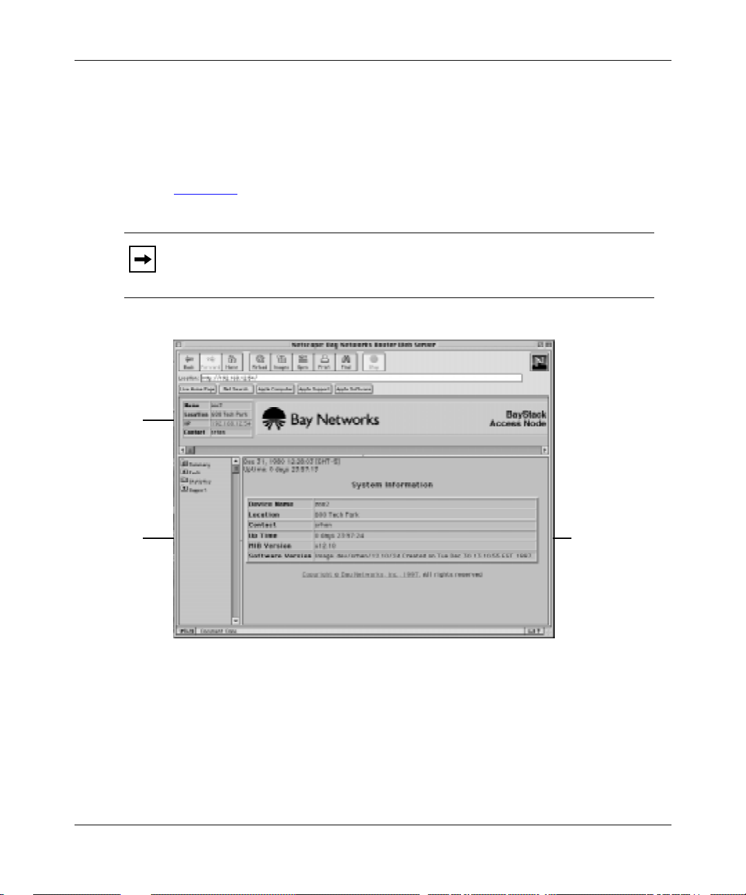
Click on Summary > PROMs in the na viga tional frame to view the summary
information for the PROM modules in the device. Figure 4-4 shows a sample
PROM summary displa y.
Figure 4-4. PROM Information Summary
For each router slot , the PROM summary lists the revision number and the date
and time of installati on for the Boot PROM and for the Diagnostic PROM in that
slot.
4-6 303552-A Rev 00
Page 39

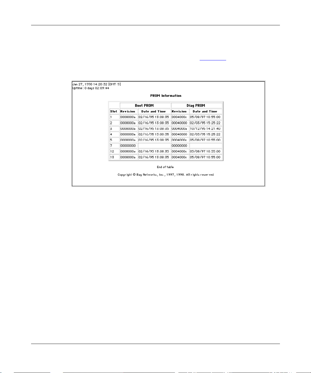
Viewing Software Image Summary Information
Click on Summary > Software in the navigational frame to view the summary
information for the software image on the specified device. Figure 4-5 show s a
sample software image summary display.
Using the HTTP Server
Figure 4-5. Software Image Information Summary
For each router slot , the software image display lists the name of the image file,
the source of that ima ge, the date and tim e the imag e was create d, and the na me of
the configur ation file.
Troubleshooting tip: Each slot should identify exactly the same image
Note:
and config file. The existence of differences indicates a possible problem that
needs attention.
303552-A Rev 00 4-7
Page 40

Managing Your Network Using the HTTP Server
Viewing System Resource Summary Information
Click on Summary > Resources in the navi gational frame to view the summar y
information for the system re sources on the spe cified hardw are device. Figure 4-6
shows a sample system res ources summary display.
Figure 4-6. System Resource Summary
For each router slot, the syst em resources displ ay lists the usage data for the CPU,
memory, and buffers in that slot.
4-8 303552-A Rev 00
Page 41

Viewing System Task Summary Information
Click on Summary > Tasks in the navigational frame to view the summary
information for the syste m tasks on the specified hardware device. Figure 4-7
shows a sample system tasks sum mary display.
Using the HTTP Server
Figure 4-7. System Task Summary
The system tasks summary sho ws the name of each active task, providing the
usage data for the CPU, memory, and buffers, and indicating on which slots the
task is running.
303552-A Rev 00 4-9
Page 42

Page 43

Chapter 5
Viewing Circuit Alerts and Events
This chapter describes how to use the HTTP Server to monitor c ircuit alerts and
system eve nts on a specified device. It assumes you have configured and enabled
the HTTP Server on your router, as described in Chap ter 1 , “
Server.” For a detailed description of how to isolate and correct problems with a
specific device, refer to Troubleshooting Routers.
Topic Page
Starting the HTTP
Displaying Cir cuit Alerts
Viewing the Event Log 5-2
With the HTTP Server, you can view the events and ale rts generated by the
entities on the router. Clicking on Fault reve als two additional choices. You can
view:
• All circuit alerts on the router
• All event log messages
The following sections describe these options.
5-2
303552-A Rev 00 5-1
Page 44

Managing Your Network Using the HTTP Server
Displaying Circuit Alerts
A circuit aler t indicates a conditi on, such as a port/interface that has been brought
down unexpe ctedly, that requires your immediat e atte ntion. To view any
exceptiona l status conditions for any interface on the router, click on Fault >
Circuit Alert in the navigational frame. Figure 5-1
display.
Figure 5-1. Circuit Alert Display
For each index item, the circuit alerts display sho ws the circuit name, the
administrati ve state , operational sta te, type, MA C address, maximum transmi ssion
unit (MTU), and line speed.
shows a sample circuit alerts
Viewing the Event Log
An event is something that happens to the operating status of a router. The router
stores the event as a single entry in a memory-resident log. The event log for a
router is the composite of all the events that occur for all the processors in the
router.
An event message provides a brief description of an event, along with the event
code associated with that event. Use the event code to look up the meaning of the
message and what you must do about it in Event Messages for Route rs. To view
the events for a router, click on Fault > Events in the navigational frame.
Figure 5-2
5-2 303552-A Rev 00
shows a sample event log display.
Page 45

Viewing Circuit Alerts and Events
Figure 5-2. Event Log Display
Specifying the Contents of the Event Log Display
By default, the event log display shows Fault, Warning, and Info event messages.
To show other event messages, cl ick on the check boxes to select the appropriate
message lev els. You can also fil l in the f ields in this frame to restrict the display to
one or more specific slots or entities, separating individual entries with spaces,
and to show only e vents that happen after a specific date and time.
Note:
All en t ity na mes are case -sens i tive. For a list of entity names, refer to
Event Messages for Router s.
303552-A Rev 00 5-3
Page 46

Managing Your Network Using the HTTP Server
Interpreting Event Messages
Event Messages for Router s provides detailed information about interpreting
event messages and taking appropriate action. Most messages document routine
occurrences that do not requir e you to do anything. Table 5-1 lists the severity
leve ls and provides brief descri ptions of them.
Table 5-1. Event Message Severity Levels
Severity Description
Fault Indi cates a major service disruption. A configuration, network, or
hardware problem usually causes such a disruption. The entities
involved keep restarting until the probl em is re solved either by the
router itself or by you.
Warning Indicates that a service acted in an unexpected manner.
Info Indicates routine events. Usually, no action is required.
Trace Provides a detai led history of ev erythi ng that happens on the router.
Because of the amount of in formation that the Trace function records,
Bay Networks recommends viewing t his type of message only when
diagnosing specific network problems.
Debug Indicates informati on that Bay Networks Customer Support uses . With
few exceptions, these messages do not appear in
Routers.
Event Messages for
5-4 303552-A Rev 00
Page 47

Chapter 6
Viewing Router Service Statistics
Examining the router’s statistics along with the event log can give you a picture of
how well your router is wor king. When you click on Statistics in the na vigational
frame, the folder opens to show three more folders: Services, Por ts, an d Protocols ,
each containing subordinate links. This chapter shows the Services statistics.
Chapter 7
Topic Page
shows the Port statis tics, and Chapter 8 shows the Protocols statistics.
Viewing TFTP Statist ics
Viewing TCP Statistic s 6-3
Viewing FTP Statistic s 6-4
Viewing Telnet Statistics 6-4
Viewing BootP Statistics 6-5
Viewing SNMP Statistics 6-7
Viewing HTTP Statistic s 6-10
6-2
Clicking on Statistics > S ervices displays links to the following services:
• TFTP
•TCP
•FTP
• Telne t
• BootP
•SNMP
• HTTP
303552-A Rev 00 6-1
Page 48

Managing Your Network Using the HTTP Server
To get statistical information about any of these services, click on the appropriate
link in the navigational frame. The following sections show these displays.
This manual presents the de tails of the HTTP statistics. Detailed
Note:
descriptions of statistics for the other services are in the manuals for each
service.
Viewing TFTP Statistics
Click on Statistics > Services > TFTP or on the text TFTP to see the statistical
information for the Trivial File Transfer Protoc ol (TFTP). Figure 6-1
example of a TFTP statistic s display .
shows an
Figure 6-1. TFTP Statistics
6-2 303552-A Rev 00
Page 49

Viewing TCP Statistics
Click on Statistics > Servi ces > TCP to vie w statistical informat ion for the
Trans mission Control Protocol (TCP). Figure 6-2 shows an example of a TCP
statistics display.
Viewing Router Service Statistics
Figure 6-2. TCP Statist ic s
303552-A Rev 00 6-3
Page 50

Managing Your Network Using the HTTP Server
Viewing FTP Statistics
Click on Statistics > Servi ces > FTP to vie w statistical informat ion for the File
Transfer Protocol (FTP). Figure 6-3 shows an example of an FTP statistics
display.
Figure 6-3. FTP Statistics
Viewing Telnet Statistics
Click on Statistics > Services > Telnet to view the statistics for Telnet services.
Figure 6-4 shows an example of a Telnet statistics display.
Figure 6-4. Telnet Statistics
6-4 303552-A Rev 00
Page 51

Viewing BootP Statistics
Clicking on Statistics > S ervices > Bootp reveals several subordinate links:
Traffic, Interfaces, Clients, Preferred Srv (Servers), and Relay Agents. The
following se ctions show example s of these displays.
Viewing BootP Traffic Statistics
Click on Statistics > Servi ces > Bootp > Traffic or on the text Bootp to view
statistical information for BootP traffic. Figure 6-5 shows an example of a BootP
traffic statistics display.
Viewing Router Service Statistics
Figure 6-5. BootP Traffic Statistics
Viewing BootP Interface Statistics
Click on Statistics > Services > Bootp > Interfaces to view statistical information
for BootP relay agent inte rfaces. Figure 6-6 shows an example of a BootP relay
agent interface statistics display.
303552-A Rev 00 6-5
Page 52

Managing Your Network Using the HTTP Server
Figure 6-6. BootP Relay Agent Interface Statistics
Viewing BootP Client Statistics
Click on Stat istics > Services > Bootp > Clients to view statistical inf ormation for
BootP clients. Figure 6-7 shows an example of a BootP client statistic s display .
Figure 6-7. BootP Client Statistics
Viewing BootP Preferred Server Statistics
Click on Statistics > Services > Bootp > Preferred Srv to view statistical
information for BootP preferred servers. Figure 6-8 shows an example of a Boot P
preferred servers statistics display.
6-6 303552-A Rev 00
Page 53

Figure 6-8. BootP Preferred Server Statistics
Viewing BootP Relay Agent Statistics
Click on Statistics > Services > Bootp > Relay Agents to view statistical
information for BootP rela y age nts. Figur e 6-9 shows an example of a BootP relay
agents statistic s display .
Viewing Router Service Statistics
Figure 6-9. BootP Relay Agent Statistics
Viewing SNMP Statistics
Clicking on Statisti cs > Services > SNMP in the navigational frame reveals the
following subor dinate links: Counters, Communities, Entity Traps, and
Exceptions. The following sections show examples of these displays.
303552-A Rev 00 6-7
Page 54

Managing Your Network Using the HTTP Server
Viewing SNMP Counter Statistics
Click on Statistics > Servi ces > SNMP > Counters or on the text SNMP to view
statistical information for SNMP counters. Figure 6-10 shows an example of the
SNMP counters statistics display.
Figure 6-10. SNMP Counter Statistics
Viewing SNMP Community Statistics
You must have Manager-level access privileges to view the statistics for SNMP
communities. If you logged in with user-lev el privileges, HTTP prompts you to
enter the manager login name and password.
6-8 303552-A Rev 00
Page 55

Click on Statistics > Servi ces > SNMP > Communities to view statistical
information for SNMP communities. Figure 6-11 shows an example of an SNMP
communities statistics display.
Figure 6-11. SNMP Community Statistics
Viewing SNMP Entity Trap Statistics
Viewing Router Service Statistics
Click on Statist ics > Services > SNMP > Entit y Traps to view SNMP entity traps .
Figure 6-12 shows an example of an SNMP entity trap statistics display with no
data.
Figure 6-12. SNMP Entity Trap Statistics
303552-A Rev 00 6-9
Page 56

Managing Your Network Using the HTTP Server
Viewing SNMP Exception Statistics
Click on Statistics > Services > SNMP > Exceptions to view SNMP exceptions
statistics. Figure 6-13 shows an example of an SNMP exceptions statistics display
with no data.
Figure 6-13. SNMP Exception Statistics
Viewing HTTP Statistics
Clicking on Statisti cs > Services > HTTP in the navigational fr ame re veals the
following subor dinate links: Configur ation, Counters, Requests, and Responses.
The followin g sections show examples of these displays. The explanations tha t
follow the scr eens are longer than for other services, because these statistics are
not currently described elsewhere.
HTTP Server statistics are also accessible through the Site Manager
Note:
Statistics Manager. Appendix B, “Viewing HTTP S erver Statistics Using the
Statistics Manager,” shows and brief ly describes the Statistics Manager
displays for the HTTP Server.
6-10 303552-A Re v 00
Page 57

Viewing HTTP Server Configuration Statistics
Click on Statistics > Servi ces > HTTP > Conf iguration to view HTTP Server
configura tion statistics. Figure 6-14 shows an example of an HTTP Server
configura tion statistics displa y.
Figure 6-14. HTTP Server Configuration Statistics
Viewing Router Service Statistics
The following is a br ief description of the se statistics, take n from the HTTP MIB.
• State -- Whether the server is enabled or disabled.
• Status -- Whether the server is curre ntly up, down, initializ ing, or not present.
• Port -- The port number on whic h this server listens to requests.
• Max. Cache Count -- The maximum number of ar chives that will be cached in
system RAM. Increasing this value can improve pe rformance for multiple
simultaneous reques ts at the cost of gre ater memory usage.
• Max. Cache Age -- The maximum number of seconds that an archive is
cached in system RAM.
303552-A Rev 00 6-11
Page 58

Managing Your Network Using the HTTP Server
Viewing HTTP Counter Summary Statistics
Click on Statistics > Servi ces > HTTP > Counters or on the te xt HTTP to view
summary statistic al information for HTTP. Figure 6-15 shows an example of an
HTTP counters statistical display.
Figure 6-15. HTTP Summary Statistics
These statistics provide the following information:
• Total Requests Received -- The total number of requests that this entity
received.
• Total Request Errors -- The total number of request errors that this entity
detected (as se rver ).
• Total Request Discards -- The total numb er of requests that this entity
discarded (as server ).
• Total Responses -- The tota l number of responses that this entity generated or
received.
• Total In Unknowns -- The total number of unknown messages that this entity
received.
• Total Rx Octets -- The total number of bytes tha t this entity received.
• Total Tx Octets -- The total number of byte s that this entity transmitted.
• Total Time Outs -- The tot al number of timeouts for this entity.
• Start Time -- The date and time that the HTTP services were enabled.
6-12 303552-A Re v 00
Page 59

Viewing HTTP Request Statistics
Click on Statistics > Servi ces > HTTP > Requests to view the HTTP request
statistics . Figure 6-16 shows an example of an HTTP request stat istics display.
Figure 6-16. HTTP Request Statistics
Viewing Router Service Statistics
These statistics provide the following information:
• Method -- The HTTP standard request method to which these stati stic s apply.
• Total In -- The number of requests of this type that this entity received.
• In Last Time -- The date and time the last request was receive d.
303552-A Rev 00 6-13
Page 60

Managing Your Network Using the HTTP Server
Viewing HTTP Response Statistics
Click on Statistics > Servi ces > HTTP > Responses to view the HTTP response
statistics . Figure 6-17 shows an example of an HTTP response stat istics display.
Figure 6-17. HTTP Response Statistics
The following is a br ief description of the se statistics, take n from the HTTP MIB.
• Status -- An HTTP standard code and message descriptio n indic ating the
status of the response.
• Total Out -- The number of times this response was gener ated.
• Out Last Tim e -- The date and tim e when the most recent response was sent.
6-14 303552-A Re v 00
Page 61

Chapter 7
Viewing Router Port Statistics
Clicking on Statistics > P orts displays the following folders in the navigational
frame:
•Ethernet
• Sync
• FDDI
• HSSI
• Token Ring
To get statistical information about any port type, click on the appropriate link.
Each port-type folder contains links to summary statistics, traffic (number of
packets transmi tted and receive d) statistics, receive error statistics, and transmit
error statistics. All but Ethernet also display system error statistics. The following
sections show and briefly describe these displays.
Topic Page
Changing the Administrative Status of a Port 7-2
Viewing Tr affic Statistics for All Ports 7-2
Viewing Ethernet Port Stati stics 7-3
Viewing Synchronous (Sync) P ort Statistics 7-6
Viewing FDDI Port Statistics 7-9
Viewing HSSI Port Statistics 7-12
Viewing Token Ring Port Statistics 7-15
303552-A Rev 00 7-1
Page 62

Managing Your Network Using the HTTP Server
Changing the Administr ative Status of a Port
A user who has Manager-level access privileges can click on the first column of
the table in the summary statistics window for any port type to change the
administrative setting of the port.
Caution:
communicating with a device causes a loss of connecti vity with the device.
The Enabled column displays the administrative setting, but it is not a clickable
link. The State column shows the operational state of the port (up or down). If the
Enabled column sho ws that the port is enabled, but the State column shows that
the port is down, the re is a problem with the port.
Disabling the interface through which your Web browser is
Viewing Traffic Statistics for All Ports
To view traffic statistics for all ports, do one of the following:
• Click on the text Statistics.
• Click on the Statistics folder, then on the text Port.
Figure 7-1
shows an example of a port tra ffic statistics display.
7-2 303552-A Rev 00
Page 63

Figure 7-1. Port Traffic Statistics
Viewing Ethernet Port Statistics
Viewing Router Port Statistics
Clicking on Statisti cs > Port > Ethernet in the navigational frame reveals the
following subor dinate links: Summary, Traffic, Rx Errors, and Tx Errors. The
following se ctions show example s of these displays.
303552-A Rev 00 7-3
Page 64

Managing Your Network Using the HTTP Server
Viewing Ethernet Summary Statistics
Click on Stati stics > Ports > Et hernet > Summary or on t he word Ethernet to view
Ethernet summary stati stics. Figure 7-2 shows an example of an Ethernet
summary statistic s display.
Figure 7-2. Ethernet Summary Statistics
Viewing Ethernet Traffic Statistics
Click on Statistics > Ports > Ethe rnet > Traffic to view Ethe rnet tr affic statistics.
Figure 7-3 shows an example of an Ethernet traffic statistics display.
Figure 7-3. Ethernet Traffic Statistics
7-4 303552-A Rev 00
Page 65

Viewing Ethernet Receive Error Statistics
Click on Statistics > Ports > Ethe rnet > Rx Errors to view Ethernet receive error
statistics . Figure 7-4 shows an example of an Ethernet receive error stat istics
display.
Figure 7-4. Ethernet Receive Error Statistics
Viewing Ethernet Transmit Error Statistics
Viewing Router Port Statistics
Click on Statistics > Ports > Ethe rnet > Tx Error s to view Ethernet transmit error
statistics . Figure 7-5 shows an example of an Ethernet transmit error sta tistics
display.
Figure 7-5. Ethernet Transmit Error Statistics
303552-A Rev 00 7-5
Page 66

Managing Your Network Using the HTTP Server
Viewing Synchronous (Sync) Port Statistics
Clicking on Statisti cs > Ports > Sync in the navigational frame reveals the
following subor dinate links: Summary, Traffic, Rx Errors, Tx Errors, and Sys
Errors. The following sections show examples of these displays.
Viewing Synchronous Summary Statistics
Click on Statistics > Ports > Sync > Summary or on the word Summary to view
synchronous summary statistics. Figure 7-6 shows an example of a synchronous
summary statistic s display.
Figure 7-6. Synchronous Summary Statistics
7-6 303552-A Rev 00
Page 67

Viewing Synchronous Traffic Statistics
Click on Statistics > Ports > Sync > Traffic to view synchronous traffic statistics.
Figure 7-7 shows an example of a synchronous traffic statistics display.
Figure 7-7. Synchronous Traffic Sta tist i cs
Viewing Synchronous Receive Error Statistics
Viewing Router Port Statistics
Click on Statistics > Ports > Sync > Rx Errors to view sync hronous receive e rror
statistics. Figure7-8
shows an example of a synchronous receive error sta tistics
display.
Figure 7-8. Synchronous Receive Error Statistics
303552-A Rev 00 7-7
Page 68

Managing Your Network Using the HTTP Server
Viewing Synchronous Transmit Error Statistics
Click on Statisti cs > Ports > Sync > Tx Errors to view sync hronous transmit error
statistics . Figure 7-9 shows an example of a synchronous transmit error statistics
display.
Figure 7-9. Synchronous T ransmit Error Statistics
Viewing Synchronous System Error Statistics
Click on Statistics > Ports > Sync > Sys Errors to view synchronous system error
statistics . Figure 7-10 shows an example of a synchronous system error statistics
display.
Figure 7-10. S ynchronous System E rror Stat i st ic s
7-8 303552-A Rev 00
Page 69

Viewing F D DI Por t Sta t istics
Clicking on Statisti cs > Ports > FDDI in the navigational frame reveals the
following subor dinate links: Summary, Traffic, Rx Errors, Tx Errors, and Sys
Errors. The following sections show examples of these displays.
Viewing FDDI Summary Statistics
Click on Statist ics > Ports > FDDI > Summary or on the text FDDI to view FDDI
summary statistic s. Figure 7-11 shows an example of an FDDI summary statistics
display.
Viewing Router Port Statistics
Figure 7-11. FDDI Summary Statistics
303552-A Rev 00 7-9
Page 70

Managing Your Network Using the HTTP Server
Viewing FDDI Traffic Statistics
Click on Statistics > Ports > FDDI > Traffic to view FDDI traffic statistics.
Figure 7-12 shows an example of an FDDI traffic statistics display.
Figure 7-12. FDDI Traffic Statistics
Viewing FDDI Receive Error Statistics
Click on Statistics > Ports > FDDI > Rx Errors to view FDDI receive error
statistics. Figure 7-13 shows an example of an FDDI recei ve error statistics
display.
Figure 7-13. FDDI Receive Error Statistics
7-10 303552-A Re v 00
Page 71
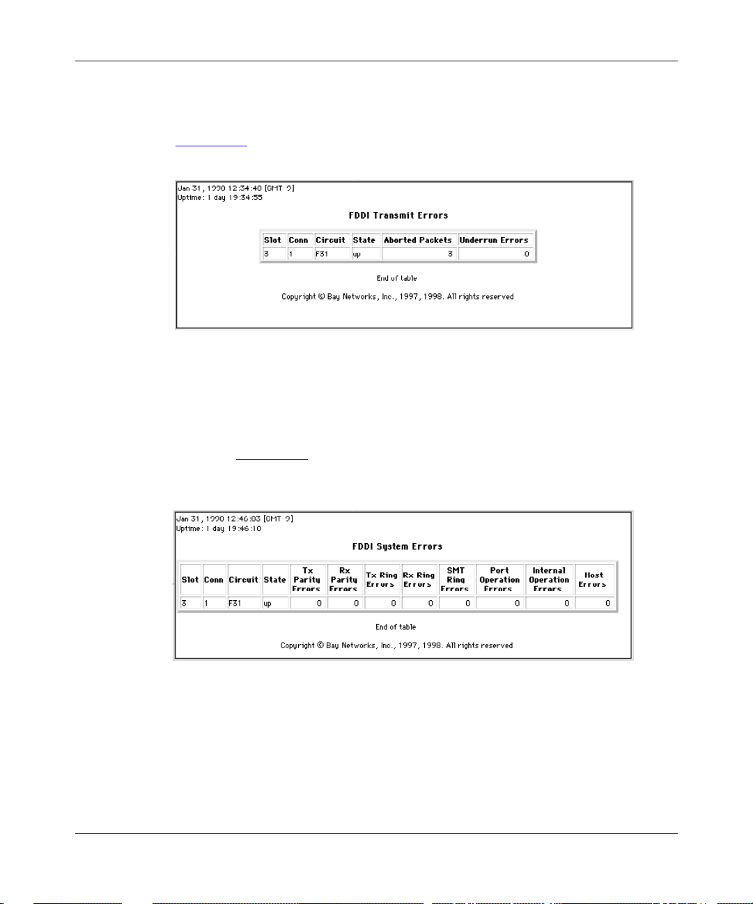
Viewing FDDI Transmit Error Statistics
Click on Statistics > Ports > FDDI > Tx Errors to view FDDI transmit errors.
Figure 7-14 shows an example of an FDDI transmit error statistics display.
Figure 7-14. FDDI Tran smit Error Statistics
Viewing FDDI System Error Statistics
Viewing Router Port Statistics
Click on Statistics > Ports > FDDI > Sys Errors to view FDDI system error
statistics. Figure 7-15 shows an example of an FDDI system error statistics
display.
Figure 7-15. FDDI Sys te m Error Statist i cs
303552-A Rev 00 7-11
Page 72

Managing Your Network Using the HTTP Server
Viewing H SS I Por t St a t is t i c s
Clicking on Statistics > P orts > HSSI in the navigational frame reveals the
following subor dinate links: Summary, Traffic, Rx Errors, Tx Errors, and Sys
Errors. The following sections show examples of these displays.
Viewing HSSI Summary Statistics
Click on Statistics > Ports > HSSI > Summary or on the text HSSI to view HSSI
summary statistic s. Figure 7-16 shows an example of a HSSI summary statistic s
display.
Figure 7-16. HSSI Summary Statistics
7-12 303552-A Re v 00
Page 73

Viewing HSSI Traffic Statistics
Click on Statistics > Ports > HSSI > T r affic to view HSSI traffic statistics.
Figure 7-17 shows an example of a HSSI traffic statistics display.
Figure 7-17. HSSI Traffic Statistics
Viewing HSSI Receive Error Statistics
Viewing Router Port Statistics
Click on Statistics > Ports > HSSI > Rx Errors to view HSSI receive error
statistics . Figure 7-18 shows an example of a HSSI receive error stati stics display.
Figure 7-18. HSSI Receive Error Statistics
303552-A Rev 00 7-13
Page 74

Managing Your Network Using the HTTP Server
Viewing HSSI Transmit Error Statistics
Click on Statistics > Ports > HSSI > Tx Errors to view HSSI transmit error
statistics. Figure 7-19 shows an example of a HSSI transmit error statistics
display.
Figure 7-19. HSSI Tran smit Error Statistics
Viewing HSSI System Error Statistics
Click on Statistics > Ports > HSSI > Sys Errors to view HSSI system error
statistics . Figure 7-20 shows an example of a HSSI system error statistics display.
Figure 7-20. HSSI System Error Statistics
7-14 303552-A Re v 00
Page 75

Viewing Token Ring Port Statistics
Clicking on Statisti cs > Ports > T oken Ring in the navigatio nal frame reveals the
following subor dinate links: Summary, Traffic, Rx Errors, Tx Errors, and Sys
Errors. The following sections show examples of these displays.
Viewing Token Ring Summary Statistics
Click on Statistics > Ports > Token Ring > Summary or on the text Token Ring to
view token ring summary sta tistic s. Figure 7-21 shows an example of a token ring
summary statistic s display.
Viewing Router Port Statistics
Figure 7-21. Toke n Ring Summary Statistics
303552-A Rev 00 7-15
Page 76

Managing Your Network Using the HTTP Server
Viewing Token Ring Traffic Statistics
Click on Statistics > Ports > Token Ring > Traffic to view token ring traffic
statistics. Figure 7-22 shows an example of a token ring traffic statistics display.
Figure 7-22. Token Ring Tra ffic Statistics
Viewing Token Ring Receive Error Statistics
Click on Statistics > Ports > Token Ring > Rx Errors to view token ring receive
error statistic s. Figure 7-23 shows an example of a token ring receive error
statistics display.
Figure 7-23. Token Ring Receive Error Statistics
7-16 303552-A Re v 00
Page 77

Viewing Token Ring Transmit Error Statistics
Click on Statistics > Ports > Token Ring > Tx Errors to view token ring transmit
error statistic s. Figure 7-24 shows an example of a token ring transmit error
statistics display.
Figure 7-24. Token Ring Transmit Error Statistics
Viewing Token Ring System Error Statistics
Viewing Router Port Statistics
Click on Statistics > Ports > Token Ring > Sys Errors to view token ring system
error statistic s. Figure 7-25 shows an example of a token ring system error
statistics display.
Figure 7-25. Token Ring System Error Statistics
303552-A Rev 00 7-17
Page 78

Page 79

Chapter 8
Viewing Router Protocol Statistics
Clicking on Statisti cs > Protocols displays the follo wing folders in the
navigat ional frame:
•IP
• IPX
• AppleTalk
To get statistical information about any protocol type, clic k on the appropriate
link. Each protocol folder contains links to summary statistics, tr affic statistics
(number of packets transmitted and received), and interface statistics, as well as to
other statistic s specific to that protoc ol. The following sections show and briefly
describe these displays.
Topic Page
Changing the Administrative Status of a Port
Viewing IP Statistics 8-2
Viewing IPX Statistics 8-11
Viewing AppleTalk Stati sti cs 8-17
303552-A Rev 00 8-1
8-2
Page 80

Managing Your Network Using the HTTP Server
Changing the Administr ative Status of a Port
A user who has Manager-level access privileges can click on the first column of
the table in the interface statistics window for any proto col type to change the
administrative setting of the port.
Caution:
communicating with the device causes a loss of connecti vity with the device.
The Enabled column displays the administrative setting, but it is not a clickable
link. The State c olumn shows the operational state of the int erface (up or down). If
the Enabled column shows tha t the interface is enabled, b ut the State column
shows that the interface is down, there is a problem with the interface.
Disabling the IP interface through which your browser is
Viewing IP Statistics
Clicking on Statisti cs > Protocols > IP in the navigational frame reveals the
following subor dinate links: Summary, Traffic, Interfaces, Routes, ARP Cache,
RIP, and ICMP. The following sections show examples of these displays.
8-2 303552-A Rev 00
Page 81
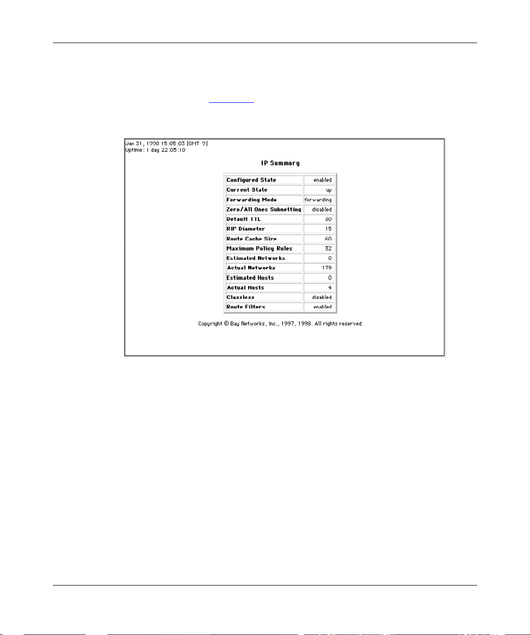
Viewing IP Summary Statistics
Click on Statistics > Protoc ols > IP > Summary or on the text IP to view IP
summary statistic s. Figure 8-1 shows an exa mple of an IP summary statistics
display.
Viewing Router Protocol Statistics
Figure 8-1. IP Summary Statistics
303552-A Rev 00 8-3
Page 82

Managing Your Network Using the HTTP Server
Viewing IP Traffic Statistics
Click on Statistics > Protoc ols > IP > Traffic or on the word Protocols to view IP
traffic statistics. Figure 8-2 show s an example of an IP traffic statistics display.
Figure 8-2. IP Traffi c Statistics
8-4 303552-A Rev 00
Page 83

Viewing IP Interface Statistics
Click on Statistics > Pr otocols > IP > Interfaces to view IP interface s tatistics.
Figure 8-3 shows an example of an IP interface statistics display.
Viewing Router Protocol Statistics
Figure 8-3. IP Interface Statistics
303552-A Rev 00 8-5
Page 84

Managing Your Network Using the HTTP Server
Viewing IP Route Statistics
Click on Statistics > Protoc ols > IP > Routes to view IP routing table statistics.
Figure 8-4 shows an example of an IP routing table statistics display.
Figure 8-4. IP Route Statistics
8-6 303552-A Rev 00
Page 85

Viewing IP ARP Cache Statistics
Click on Sta tistics > Protocols > IP > AR P Cache to view IP ARP cache statistics.
Figure 8-5 shows an example of an IP ARP cache statistics display.
Viewing Router Protocol Statistics
Figure 8-5. IP ARP Cache Statistics
303552-A Rev 00 8-7
Page 86

Managing Your Network Using the HTTP Server
Viewing IP RIP Interface Statistics
Click on Statistics > Protoc ols > IP > RIP to view RIP interface table stat istics.
Figure 8-6 shows an examp le of an IP RI P interface table stat istics display.
Figure 8-6. IP RIP Interface Statistics
Viewing IP ICMP Statistics
Clicking on Statistics > P rotocols > IP > ICMP (Internet Control Message
Protocol) in the navigational frame reveals the following subordinate links:
Counters, Received, and Transmitted. The following sections show examples of
these displays.
8-8 303552-A Rev 00
Page 87

Viewing ICMP Counter Statistics
Click on Statistics > Protoc ols > IP > ICMP > Counters or on the text ICMP to
view ICMP counters statisti cs. Fig u re8-7 shows an example of an ICMP counters
display.
Viewing Router Protocol Statistics
Figure 8-7. ICMP Counter Statistics
303552-A Rev 00 8-9
Page 88

Managing Your Network Using the HTTP Server
Viewing ICMP Received Statistics
Click on Statistics > Pr otocols > IP > ICMP > Received to view ICMP received
statistics . Figure 8-8 shows an example of an ICMP recei ve d statistics display.
Figure 8-8. ICMP Received Statistics
8-10 303552-A Re v 00
Page 89

Viewing ICMP Transmitted Statistics
Click on Statistics > Pr otocols > IP > ICMP > Transmitted to view ICMP
transmitted statistics. Figure 8-9 shows an example of an ICMP transmitted
statistics display.
Viewing Router Protocol Statistics
Figure 8-9. ICMP Transmitted Statistics
Viewing IPX Stat is t ic s
Clicking on Statisti cs > Protocols > IPX in the navigational frame reveals the
following subor dinate links: Summary, Traffic, Interfaces, Forwarding, Hosts,
Routes, Services, RIP, and SAP. The following sect ions show examples of these
displays.
303552-A Rev 00 8-11
Page 90

Managing Your Network Using the HTTP Server
Viewing IPX Summary Statistics
Click on Statistics > Protoc ols > IPX > Summary or on the text IPX to view IPX
summary statistic s. Figure 8-10 shows an ex ample of an IPX summary statistics
display.
Figure 8-10. IPX Summary Statistics
8-12 303552-A Re v 00
Page 91

Viewing IPX Traffic Statistics
Click on Statistics > Protoc ols > IPX > Traffic to view IPX traffic statistics.
Figure 8-11 shows an example of an IPX traffic statistics display.
Figure 8-11. IPX Traffic Statistics
Viewing Router Protocol Statistics
Viewing IPX Interface Statistics
Click on Statistics > Protoc ols > IPX > Interfaces to view IPX interface tabl e
statistics. Figure 8-12 shows an example of an IPX interface table statistics
display.
Figure 8-12. IPX Interface Statistics
303552-A Rev 00 8-13
Page 92

Managing Your Network Using the HTTP Server
Viewing IPX Forwarding Statistics
Click on Statistics > Protocols > IPX > Forwarding to view IPX forwarding table
statistics. Figure 8-13 shows an example of an IPX forwarding table statistics
display.
Figure 8-13. IPX Forwarding Statistics
Viewing IPX Host Statistics
Click on Statistics > Protocols > IPX > Hosts to view IPX hosts table statistics.
Figure 8-14
shows an example of an IPX hosts table sta tistics display.
Figure 8-14. IPX Host Statistics
8-14 303552-A Re v 00
Page 93

Viewing IPX Route Statistics
Click on Statist ics > Prot ocols > I PX > Routes to v ie w IPX routing t able s tatist ics.
Figure 8-15 shows an example of an IPX routes statistics displa y.
Figure 8-15. IPX Route Statistics
Viewing Router Protocol Statistics
Viewing IPX Service Statistics
Click on Statistics > Protoc ols > IPX > Servi ces to view IPX service table
statistics . Figure 8-16 shows an example of an IPX services display .
Figure 8-16. IPX Service Statistics
303552-A Rev 00 8-15
Page 94

Managing Your Network Using the HTTP Server
Viewing IPX RIP Interface Statistics
Click on Statistics > Protocols > IPX > RIP to view IPX RIP interface statistics.
Figure 8-17 shows an examp le of an IPX RI P int erfac e statistics display.
Figure 8-17. IPX RIP Interface Statistics
Viewing IPX SAP Statistics
Click on Statistics > Protoc ols > IPX > SAP to vie w IPX SAP interface statistics.
Figure 8-18 shows an examp le of an IPX SA P int erfac e stat isti cs display.
Figure 8-18. IPX SAP Interface Statistics
8-16 303552-A Re v 00
Page 95

Viewing AppleTalk Statistics
Clicking on Statistics > P rotocols > AppleTalk in the navigational frame reveals
the follow ing subordinate links: Summary, Traffic, Interfaces, Routes, ARP
Cache, and Zones. The following sections show examples of these displays.
Viewing AppleTalk Summary Statistics
Click on Statistics > Protoc ols > AppleT alk > Summary or on the text AppleTalk
to view AppleTalk sum m ary statistics. Figure 8-19 shows an example of an
AppleTalk summary statistics display.
Viewing Router Protocol Statistics
Figure 8-19. AppleTalk Summary Statistics
303552-A Rev 00 8-17
Page 96

Managing Your Network Using the HTTP Server
Viewing AppleTalk Traffic Statistics
Click on Statistics > Protoc ols > AppleT alk > Traffic to view AppleTalk traffic
statistics . Figure 8-20 shows an example of an AppleTalk traffic statistics display.
Figure 8-20. AppleTalk Tra ffic Statistics
Viewing AppleTalk Interface Statistics
Click on Statistics > Protoc ols > AppleT alk > Interfaces to view AppleTalk
interface table statistics. Figure 8-21
shows an example of an AppleTalk interface
table statistic s display .
Figure 8-21. AppleTal k Interface Statistics
8-18 303552-A Re v 00
Page 97

Viewing AppleTalk Route Statistics
Click on Statistics > Protoc ols > AppleT alk > Routes to view AppleTalk routing
table statistic s. Figure 8-22 shows an example of an AppleTalk routes statistics
display.
Viewing Router Protocol Statistics
Figure 8-22. AppleTalk Route Statistics
Viewing AppleTalk ARP Cache Statistics
Click on Statis tics > Protocols > AppleTalk > ARP Tabl e to view AppleTalk ARP
table statistic s. Figure 8-23 shows an example of an AppleTalk ARP table
statistics display.
Figure 8-23. AppleTalk ARP Table Statistics
303552-A Rev 00 8-19
Page 98
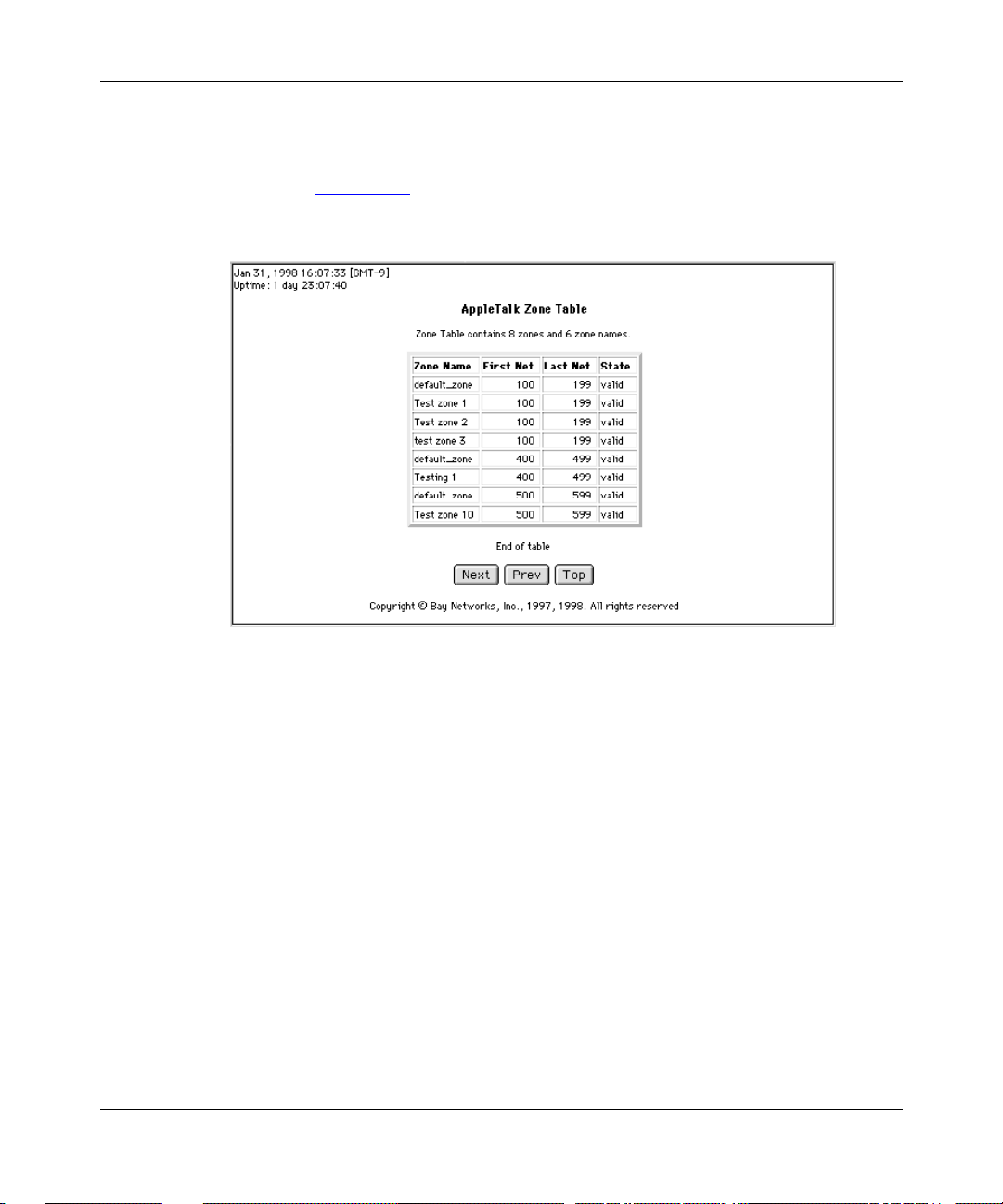
Managing Your Network Using the HTTP Server
Viewing AppleTalk Zone Statistics
Click on Statistics > Prot ocols > Apple Talk > Zones to view AppleTalk zone table
statistics . Figure 8-24 shows an example of an AppleTalk zone table statistics
display.
Figure 8-24. AppleTal k Zone Statistics
8-20 303552-A Re v 00
Page 99

Chapter 9
Customizing HTTP Server Parameters
When you start the HTTP Server on the router, default values are in effect for all
parameters. Depending on the requirements of your network, you may want to
change some of these values. This chapter includes the following information:
Topic Page
Disabling and Reenabling the HTTP Server
Specifying the Port Number for t he HTTP Server 9-3
Specifying the Maximum Number of Cached Archives 9-4
Specifying the Maximum Time of Cached Archives 9-5
For a descriptio n of all Sit e Manager parameters for HTTP Server, see
Appendix A
, “Site Manager Parameters .”
9-2
303552-A Rev 00
9-1
Page 100

Managing Your Network Using the HTTP Server
Disabling and Reenabling the HTTP Server
When you start the HTTP Server on a router, the HTTP Server is enabled b y
default. Using either the BCC or Site Manager, you can disable and reenable the
HTTP Server.
Using the BCC
To disable or reenable the HTTP Server, navigate to the http prompt and enter:
state
state
is enabled or disabled.
state
For example, to disable the HTTP Server, enter the following command:
http#
Using Site Manager
To disable or reenable
You do this System responds
1. In the Configuration M anager window,
choose
2. Choose
3. Choose
4. Choose
5. Set the
Click on
description on page A-3
6. Click on OK. You return to the Configuration Manager
state disabled
Protocols
Global Protocols
HTTP
Global
Enable/Disable
Help
.
. The HTTP menu opens.
. The Edit HTTP Global Parameters
or see the parameter
the HTTP Server
Site Manager Procedure
. The Global Protocols menu opens.
parameter.
.
, complete the following tasks:
The Protocols menu opens.
window opens.
window.
9-2
303552-A Re v 00
 Loading...