

Avaya IP Office (R3.0), IP Office Virtual Private Networking User Manual

IP Office (R3.0)
Virtual Private Networking
40DHB0002UKER Issue 3 (4th February 2005)

Page 2 - Figures
Figures................................................................................................................... 3
Contents
Introduction........................................................................................................... 4
General...................................................................................................................................4
Further Reading.............................................................................................................................. 4
Overview of IPSec and L2TP Technologies ....................................................... 5
General...................................................................................................................................5
IPSec .............................................................................................................................................. 6
L2TP ............................................................................................................................................... 7
Overview of Secure VPN Implementation .......................................................... 9
IPSec Implementation............................................................................................................. 9
L2TP Implementation............................................................................................................ 11
Guidelines..................................................................................................................................................11
Logical LAN Implementation................................................................................................. 13
Typical VPN Deployment...................................................................................................... 15
Public Access Networks ............................................................................................................... 16
Guidelines..................................................................................................................................................16
Further Reading............................................................................................................................ 16
Public Interface ............................................................................................................................. 17
Guidelines..................................................................................................................................................17
Internal LAN.................................................................................................................................. 18
Client VPN .................................................................................................................................... 18
Guidelines..................................................................................................................................................18
VPN and VoIP............................................................................................................................... 19
Bandwidth Calculation Variables...............................................................................................................20
Bandwidth Requirement Calculation............................................................................................. 21
Example 1..................................................................................................................................................21
Example 2..................................................................................................................................................22
Guidelines..................................................................................................................................................22
Maximum Load ............................................................................................................................. 23
Configuration ...................................................................................................... 24
IPSec Configuration..............................................................................................................24
The IP Security Menu ................................................................................................................... 24
Guidelines - Local and Remote IP Address/Mask configuration...............................................................26
Guidelines - Local and Remote Gateway..................................................................................................26
IKE and IPSec Policies Tabs ........................................................................................................ 27
IKE Policies tab .........................................................................................................................................28
IPSec Policies tab......................................................................................................................................29
L2TP Configuration...............................................................................................................30
L2TP/Tunnel tab ........................................................................................................................... 30
L2TP/L2TP tab.............................................................................................................................. 31
L2TP/PPP tab ...............................................................................................................................32
Guidelines..................................................................................................................................................32
Logical LAN Menu ........................................................................................................................ 33
Guidelines..................................................................................................................................................33
Page 2 - Figures Virtual Private Networking
40DHB0002UKER Issue 3 (4th February 2005)

Configuration Examples .................................................................................... 34
Contents (Cont.)
Part 1: Basic Internet Access................................................................................................ 34
Internet Access using a Logical Interface ..................................................................................... 34
Basic Internet Access using LAN2................................................................................................36
Part 2: VPN configuration ..................................................................................................... 37
IPSec - Between Two IP Office systems over ADSL using the Logical LAN ................................ 37
L2TP/IPSec between two IP Office’s ............................................................................................ 40
Part 1 - L2TP configuration .......................................................................................................................41
Part 2 - IPSec configuration ......................................................................................................................43
IPSec Client Application (Dynamic Mode) .................................................................................... 45
Part 1 - VPN Client Configuration..............................................................................................................46
Part 2 - IP Office Configuration ................................................................................................................47
IPSec over the WAN..................................................................................................................... 49
A Numbered PPP WAN Link .....................................................................................................................49
An Un-numbered PPP WAN Link..............................................................................................................51
Part 3 VoIP Configuration ..................................................................................................... 53
Glossary .............................................................................................................. 56
Figures
Figure 1. A Virtual Private Network ........................................................................................... 4
Figure 2. An IPSec Framework ................................................................................................. 6
Figure 3. LT2P Tunneling Modes ..............................................................................................7
Figure 4. Inbound Unprotected Packet......................................................................................9
Figure 5. Inbound Unprotected Packet Type Detection........................................................... 10
Figure 6. L2TP Implementation ...............................................................................................12
Figure 7. Logical LAN Implementation ....................................................................................13
Figure 8. IP Office VPN Networking ........................................................................................15
Figure 9. The IP Security Menu............................................................................................... 24
Figure 10. IP Phase 1 and Phase 2 negotiations .................................................................... 27
Figure 11. The IKE Policies tab............................................................................................... 28
Figure 12. The IPSec Policies tab ...........................................................................................29
Figure 13. The L2TP/Tunnel Menu..........................................................................................30
Figure 14. The L2TP/L2TP tab................................................................................................ 31
Figure 15. The L2TP/PPP tab ................................................................................................. 32
Figure 16. The Logical LAN Menu........................................................................................... 33
Figure 17. Internet Access Via the Logical LAN ...................................................................... 34
Figure 18. Internet Access Via LAN2.......................................................................................36
Figure 19. IP Office to IP Office via Logical LAN ..................................................................... 37
Figure 20. L2TP/IPSec - IP Office to IP Office......................................................................... 40
Figure 21. PC running IPSec Client Application ......................................................................45
Figure 22. A Numbered PPP WAN Link .................................................................................. 49
Figure 23. An Un-numbered PPP WAN Link........................................................................... 51
Introduction Page - 4
Introduction
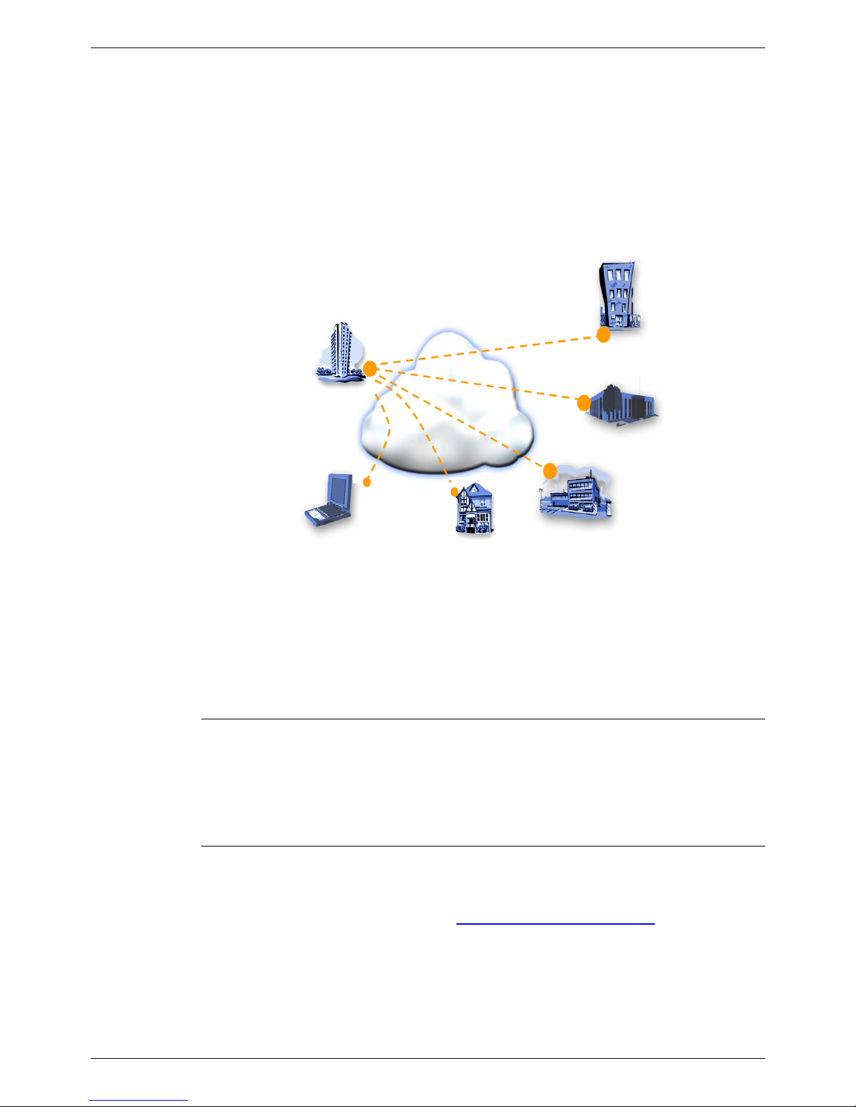
Virtual Private Networks (VPNs) have evolved from the growing needs of businesses
for more wide area network connectivity. This need has been driven by a combination
of technological progress and changing trends in work habits and work environments.
The new VPN capability in Avaya’s IP Office gives small and medium sized businesses
a cost effective alternative to private leased line or Frame Relay (FR) services for
interconnecting sites. It also allows Small Medium Businesses (SMBs) to avoid the high
costs associated with teleworkers and the mobile workforce using Remote Access
Servers (RAS). Instead they can leverage the ubiquity and low cost of the public
Internet.
Telecommuter
Telecommuter
& Home
& Home
Offices
Offices
Internet
Internet
Remote
Remote
Offices
Offices
Branch
Branch
Offices
Offices
Business
Business
Partners
Partners
Mobile
Mobile
Access
Access
Main Sites
Main Sit es
Telecommuter
Telecommuter
& Home
& Home
Offices
Offices
Internet
Internet
Remote
Remote
Offices
Offices
Branch
Branch
Offices
Offices
Business
Business
Partners
Partners
Mobile
Mobile
Access
Access
Main Sites
Main Sit es
Figure 1. A Virtual Private Network
IP Office VPN is implemented as a customer premises based VPN, by far the most
common method adopted amongst SMBs. VPN capability is integrated into the IP
Office server delivering a single box solution, with the ease of common management,
and lower total cost of ownership than a multi box solution.
General
This manual provides scenarios and worked examples for VPN implementation on an
IP Office running software level 3.0+. Throughout this manual is assumed that the
reader has networking knowledge but not necessarily any detailed understanding of
security protocols and encryption.
Further Reading
The IPSec and L2TP specifications are widely discussed in open forums. The reader is
encouraged to seek a fuller explanation than is provided within this manual. Refer to
the Virtual Private Network Consortium http://www.vpnc.org/terms.html for further
information.

Overview of IPSec and L2TP Technologies - Page 5
Overview of IPSec and L2TP Technologies
This section presents a brief overview and describes key terms and references specific
to tunneling protocols that comprise the new IP Office 3.0+ features of secure VPN
networking using Internet Security (IPSec) and L2TP. The information and discussion in
this document is specific to the following software revisions:
Equipment Software Version
IP Office (all platforms) 3.0+
SysMonitor 3.0+
Manager 3.0+
Cisco IOS® using pre-shred mode only 12.2+
NetScreen Remote VPN Client 10.0
General
For secure VPNs, the technologies that IP Office supports are:
• IPSec
• L2TP Compulsory/Voluntary (optional pre-shared secret Authentication)
IPSec is the primary VPN security protocol and is a licensable IP Office feature.
CAUTION: Throughout this document, examples are given for various VPN
scenarios. The IP addresses used must be considered as EXAMPLES
ONLY. For definitive IP addresses, always consult your Network
Administrator.
IP Office (R3.0) Virtual Private Networking Overview of IPSec and L2TP Technologies - Page 5
40DHB0002UKER Issue 3 (4th February 2005) General
Page 6 - Overview of IPSec and L2TP Technologies
IPSec
IP packets have no inherent security. Hence, where security is required, then IPSec is
used. IPSec is a method of protecting IP datagrams and provides:
1. Data origin authentication
2. Data integrity authentication.
3. Data content confidentiality.
IPSec protects IP packets by specifying the traffic to protect, how that traffic is to be
protected and to whom the traffic is sent. The method of protecting IP packets is by
using one of the IPSec protocols, the Encapsulating Security Payload (ESP) or the
Authentication Header (AH).
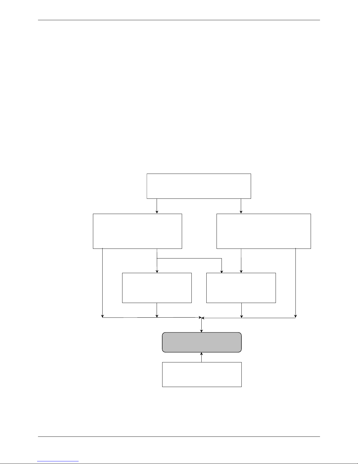
IPSec is a suite of protocols developed and maintained by the Internet Engineering
Task Force (IETF). The framework for IPSec is modular and component oriented. The
diagram below illustrates the interrelationship between all of the IPSec components that
maintain this modular approach. It is important to understand that each of these groups
serve a specific purpose and work together to provide a modular solution to Internet
security problems. By breaking IPSec into these seven different areas it become easier
to understand the objective of each group of components.
IPSec Architecture
Concepts, security requirements, definitions
and mechanisms.
A
uthentication Header (AH)
Packet format, padding contents,
mandatory algorithms and general issues
associated with authentication.
Encapsulation Securit
y
Payload (ESP)
Packet format, padding contents,
mandatory algorithms and general
issues associated with encryption.
Domain of Interpretation
(DOI)
Key Management
Describes the IETF standard-track
key managements schemes.
A
uthentication Algorithm
Describes the set of
documents used for ESP and
AH authentication.
Encryption Algorithm
Illustrates the various
encryption algorithms used
for ESP.
Figure 2. An IPSec Framework
Page 6 - Overview of IPSec and L2TP Technologies IP Office (R3.0)
General 40DHB0002UKER Issue 3 (4th February 2005)
Overview of IPSec and L2TP Technologies - Page 7
L2TP
Layer 2 Tunneling Protocol (L2TP) provides a means for tunneling IP traffic at layer 2
and is derived from two other tunneling protocols (PPTP and L2F). L2TP is built upon
the well-established Internet communications protocol Point-to-Point Protocol (PPP),
and Transmission Control Protocol/Internet Protocol (TCP/IP).
L2TP tunneling encapsulates IP data packets in PPP, for transmission through an IP
network. Upon receipt, the IP and PPP headers are stripped away, exposing the
original IP data packet. In this way encapsulation allows the transportation of IP
packets over a PPP authenticated connection.
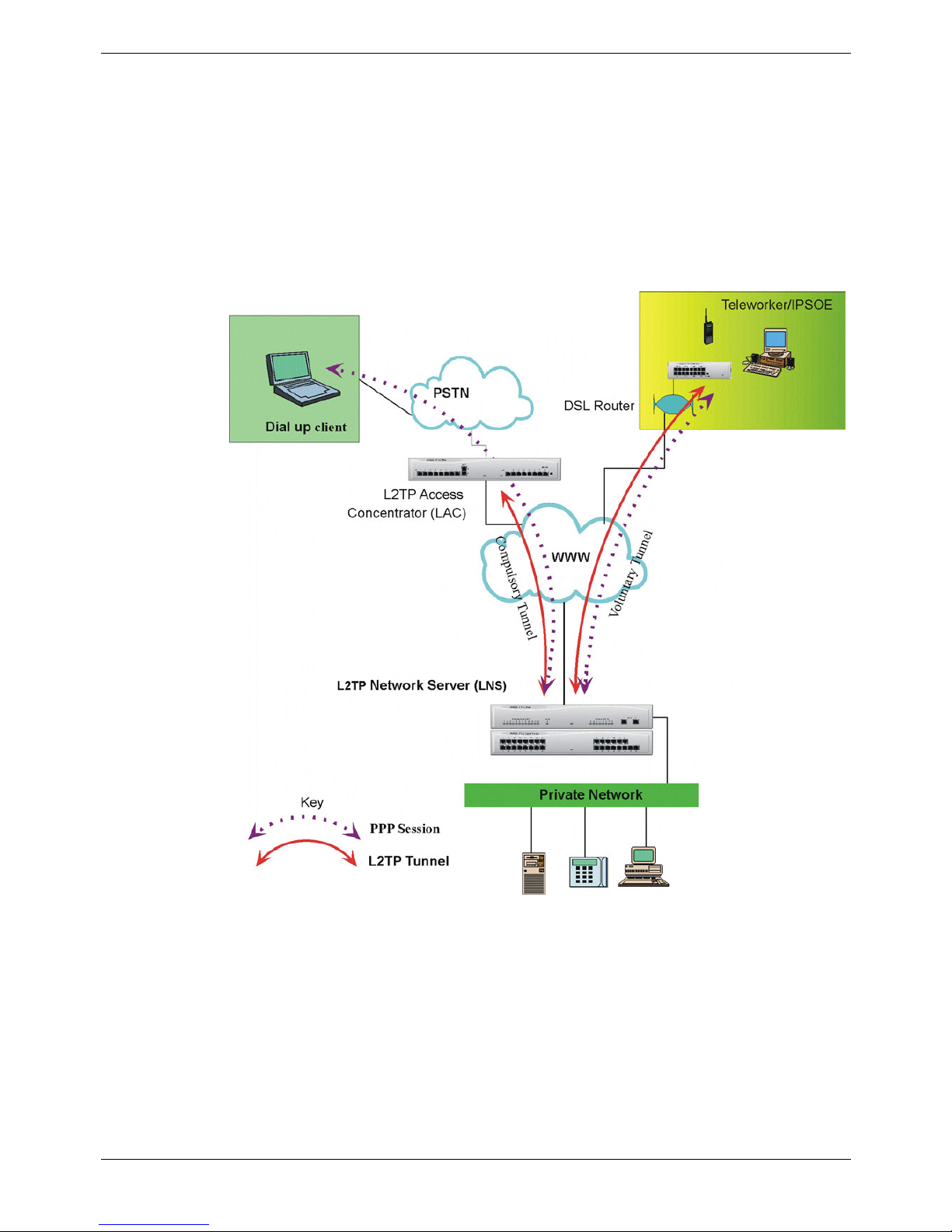
The diagram below demonstrates the two modes of tunneling that an L2TP tunnel may
operate.
Figure 3. LT2P Tunneling Modes
IP Office (R3.0) Virtual Private Networking Overview of IPSec and L2TP Technologies - Page 7
40DHB0002UKER Issue 3 (4th February 2005) General

Page 8 - Overview of IPSec and L2TP Technologies
Compulsory Tunneling
A compulsory tunnel is an L2TP tunnel which is not controlled by the user. In
compulsory tunneling the dial-up client PC accesses the Private Network by first dialing
to an L2TP Access Concentrator (LAC), which terminates the Public Switched
Telephone Network (PSTN) connection and then establishes an L2TP tunnel to the
L2TP network Server (LNS). In this mode the PPP session is established between the
dial-up client PC and the LNS and L2TP is established between the LAC and the
Network Access Server (NAS).
IP Office can be used to provide LAC operation but does not provide PPP
transportation. Under the IP Office 3.0+ implementation the incoming PPP session is
terminated locally and the L2TP tunnel is then established to the LNS. The contents of
the incoming PPP session are extracted and routed through the established tunnel in
the normal way.
Voluntary Tunneling
Voluntary tunneling mode operation describes an L2TP tunnel, which is established
directly between the user and the LNS. Once L2TP is established the PPP protocol
then runs over the session. Running voluntary tunneling is the primary operating mode
for the IP Office L2TP implementation.
The table below provides a summary of the L2TP packet exchanges that are used in
the establishment and control of an L2TP tunnel.
Message Type Description
Start-Control-ConnectionRequest (SCCRQ)
Sent by the L2TP client to establish the control connection.
Each L2TP tunnel requires a control connection to be
established before any other L2TP messages can be issued.
It includes an Assigned Tunnel-ID that is used to identify the
tunnel.
Start-Control-ConnectionReply (SCCRP)
Sent by the L2TP server to reply to the Start-ControlConnection-Request message.
Start-Control-ConnectionConnected (SCCRN)
Sent in reply to a Start-Control-Connection-Reply message
to indicate that the tunnel establishment was successful.
Outgoing-Call-Request
Sent by the L2TP client to create an L2TP tunnel. Included in
the Outgoing-Call-Request message is an Assigned Call ID
that is used to identify a call within a specific tunnel.
Outgoing-Call-Reply
Sent by the L2TP server in response to the Outgoing-CallRequest message.
Start-Control-ConnectionConnected
Sent in reply to a received Outgoing-Call-Reply message to
indicate that the call was successful.
Hello
Sent by either the L2TP client or L2TP server as a keep-alive
mechanism. If the Hello is not acknowledged, the L2TP
tunnel is eventually terminated.
WAN-Error-Notify
Sent by the L2TP server to all VPN clients to indicate error
conditions on the PPP interface of the L2TP server.
Set-Link-Info
Sent by the L2TP client or L2TP server to set PPPnegotiated options.
Call-Disconnect-Notify
Sent by either the L2TP server or L2TP client to indicate that
a call within a tunnel is to be terminated.
Stop-Control-ConnectionNotification
Sent by either the L2TP server or L2TP client to indicate that
a tunnel is to be terminated.
Page 8 - Overview of IPSec and L2TP Technologies IP Office (R3.0)
General 40DHB0002UKER Issue 3 (4th February 2005)
Overview of Secure VPN Implementation - Page 9
Overview of Secure VPN Implementation
IP Office’s secure VPN solutions comprise both IPSec and L2TP tunneling protocols.
Both of these protocols may be used independently or collectively to provide the
required secure VPN. In order to explain the IP Office secure VPN solution this section
describes each protocol implementation in turn and, for IPSec, how IP Office handles
an unprotected packet arriving at an interface.
IPSec Implementation
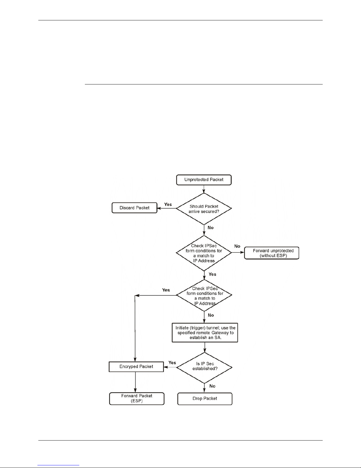
An inbound unprotected packet is one that is not protected by IPSec and is therefore
received on an interface outside an established IPSec tunnel. In the context of IPSec it
is an unsecured packet. If the inbound unprotected packet matches the condition on
any configured IPSec form then a Security Association (SA) is formed with the specified
Secure Gateway. Once the SA is established the inbound packet is secured and
forwarded to the Secure Gateway as an ESP packet.
Note: IPSec implementation on IP Office requires a valid licence.
If the packet does not match any condition set on an IPSec configuration then it is
simply forwarded unencrypted to the appropriate destination interface. The diagram
below details the case for an inbound unprotected packet.
Figure 4. Inbound Unprotected Packet
If the unprotected packet matches the configured IP address condition for an
established SA it is forwarded to the destinations using the SA.
IP Office (R3.0) Virtual Private Networking Overview of Secure VPN Implementation - Page 9
40DHB0002UKER Issue 3 (4th February 2005) IPSec Implementation
Page 10 - Overview of Secure VPN Implementation
If the unprotected packet matches a condition for which there is not an established SA
then IP Office will initiate IPSec tunnel establishment (ISAKMP) to the specified remote
gateway. Once the tunnel is established the packet is encrypted and forwarded to the
appropriate interface. In this way, an inbound unprotected packet serves as the trigger
mechanism for IPSec tunnel establishment.
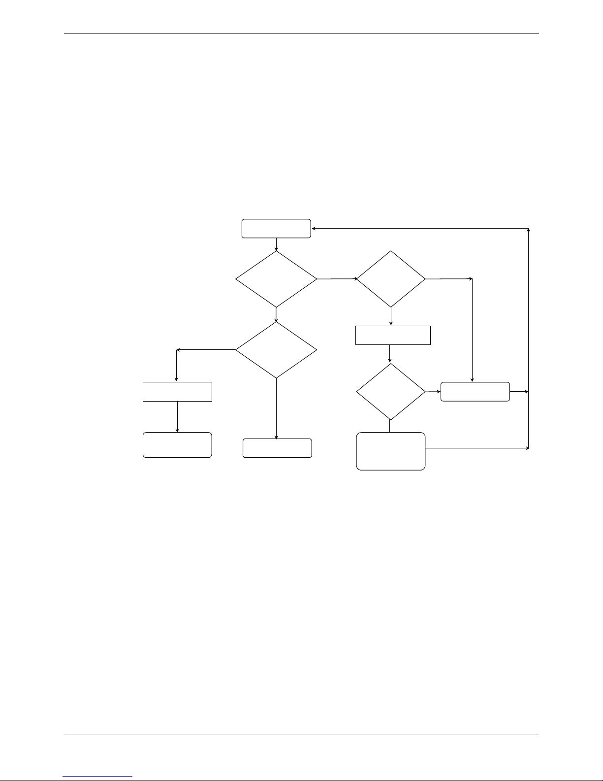
The other case for a packet arriving on an interface is where the packet is an IPSec
packet type. There are two types:
1. ISAKMP - used to establish the tunnel and thereby form the SA.
2. ESP - used to carry the encrypted data.
If the received IPSec packet is an ESP addressed to the IP Office, then IP Office will
check for a valid SA. If a valid SA is found then the packet is decrypted and forwarded.
If not, the ESP packet is discarded.
Yes
Decrypt packet
ESP
Forward packet
(ESP)
Close connection
ISAKMP
No
Listen for IPSec
Check IPSec
packet type
Check for valid
Security Association
(SA)
No
Drop packet
Setup IPSec
Security
Association
established
Is there is a source
address match on
the IPSec list?
Is IPSec mode
established?
Yes
No
Yes
Figure 5. Inbound Unprotected Packet Type Detection
Page 10 - Overview of Secure VPN Implementation IP Office (R3.0)
IPSec Implementation 40DHB0002UKER Issue 3 (4th February 2005)

Overview of Secure VPN Implementation - Page 11
L2TP Implementation
With IP Office version 3.0+, VPN implementation of an L2TP tunnel presents a routable
destination. The configured L2TP tunnel is available in the routing table as an IP
destination interface. IPSec is different in this respect in that it applies a treatment or
protection to specified IP addresses. Protected packets are encrypted packets (called
ESPs) that are routed to the appropriate destination using the routing table in the
normal way. IP Office secure VPN solutions comprise both IPSec and L2TP. The
relationship between IPSec and L2TP is therefore symmetrical and provides for the
following:
• IPSec inside L2TP: IPSec protected packets (ESP) routed to an LT2P destination
• L2TP inside IPSec: LT2P packets to be protected by IPSec
The table below details the advantages/ disadvantages of IPSec, L2TP and the
symmetrical relationship between the two:
IPSec L2TP IPSec in L2TP L2TP Inside IPSec
Advantages
• Encrypts data
Disadvantages
• Packets must not
be excessively reordered in the
same tunnel
Advantages
• Can be used for
Inter-tunneling
• PPP IP Header
compression
support
Disadvantages
• No Data
Encryption
• Packets must not
be excessively reordered in the
same tunnel
Advantages
• Can be used to
with existing LT2P
systems
Disadvantages
• L2TP negotiation
can be observed
on the Public
Network
• Packet size
Advantages
• Can be used for
inter-tunneling
• L2TP negotiation
cannot be
observed on the
Public Network
• Commonly used
by Microsoft
Disadvantages
• Packet size
Guidelines
1. IP Office is able to allow IPSec packets to pass through a NAT enable interface.
However this facility is only available when the IPSec tunnel is either originated or
terminated on a local interface.
IP Office (R3.0) Virtual Private Networking Overview of Secure VPN Implementation - Page 11
40DHB0002UKER Issue 3 (4th February 2005) L2TP Implementation
Page 12 - Overview of Secure VPN Implementation
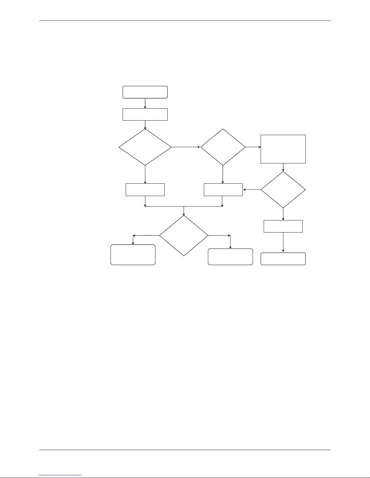
For any routable packet the routing table is referenced to determine the appropriate
destination. If the packet is for an L2TP destination then IP Office checks the status of
the tunnel. If established the packet is forwarded. If the packet is addressed to an L2TP
destination and the tunnel is not active, then IP Office uses the remote gateway entry
on the L2TP form and initiates the tunnel setup. The routable packet is queued until the
tunnel is established. When the tunnel is established the routable packet is forwarded
inside the tunnel.
No
No Yes
No
Yes
Treat as unprotected
packet
Forward to IPSec
Forward packet
to destination
Drop packet
Is the
L2TP tunnel
destination
established?
Check for an
IPSec Policy match
for this packet?
Yes
Is the packet
for an L2TP
destination?
Any packet
Check Routing Table
Forward outside
L2TP tunnel
Queue Packet
or
Use Remote
Gateway address to
establish tunnel
Forward inside
L2TP tunnel
Is the
L2TP tunnel
established?
Close L2TP after 3
failed attempts
No
Yes
Figure 6. L2TP Implementation
When the L2TP packet is to be forwarded it may be the case that the IPSec tunnel peer
or endpoint address require IPSec protection. If so, the outgoing L2TP packet is
encrypted inside IPSec, as in the case for an unprotected packet (see previous
paragraphs). In this way L2TP can be tunneled inside IPSec. If the L2TP tunnel peer
address does not require protection then an L2TP packet is sent directly without IPSec
protection.
With IP Office version 3.0+ implementation it is also permissible for an ESP packet to
be routed to an L2TP destination (i.e. using the routing table) and in this way IPSec to
tunnel inside L2TP.
Page 12 - Overview of Secure VPN Implementation IP Office (R3.0)
L2TP Implementation 40DHB0002UKER Issue 3 (4th February 2005)
Overview of Secure VPN Implementation - Page 13
Logical LAN Implementation
The Logical LAN feature is new to IP Office (2.0+ software). Logical LAN feature allows
a second LAN interface to operate together with the primary System LAN interface
(LAN 1). The Logical LAN feature allows a second LAN interface to operate together
with the primary System LAN interface (LAN1). Once a Logical LAN interface is created
and configured it is then available as an IP route destination. The table below
summaries the terms used to describe the Logical LAN feature.
Term Description
Physical LAN
For a single LAN system (IP403 and IP406) this is the actual
Ethernet interface and consists of both the Logical LAN (see below)
and the System LAN (see below).
Logical LAN
The Logical LAN has the same collision domain as the System LAN
but uses a different MAC address and operates on a different subnet.
The Logical interface can be regarded as a secondary or a subinterface to the primary System LAN (LAN1) interface – see below.
The Logical LAN provide the function of the Public or External
Interface (see page 17).
System LAN
The System LAN has the same collision domain as the Logical but
uses a different MAC address and operates on a different subnet.
When a Logical LAN is created (see above) the System LAN
becomes active and is referred to as LAN1.The System LAN
performs the function of an internal LAN.
Single LAN systems
IP Office systems that have a single LAN interface (IP403 and
IP406).
Dual LAN systems
IP Office systems that have dual Ethernet interfaces (Small Office
Edition and IP412)
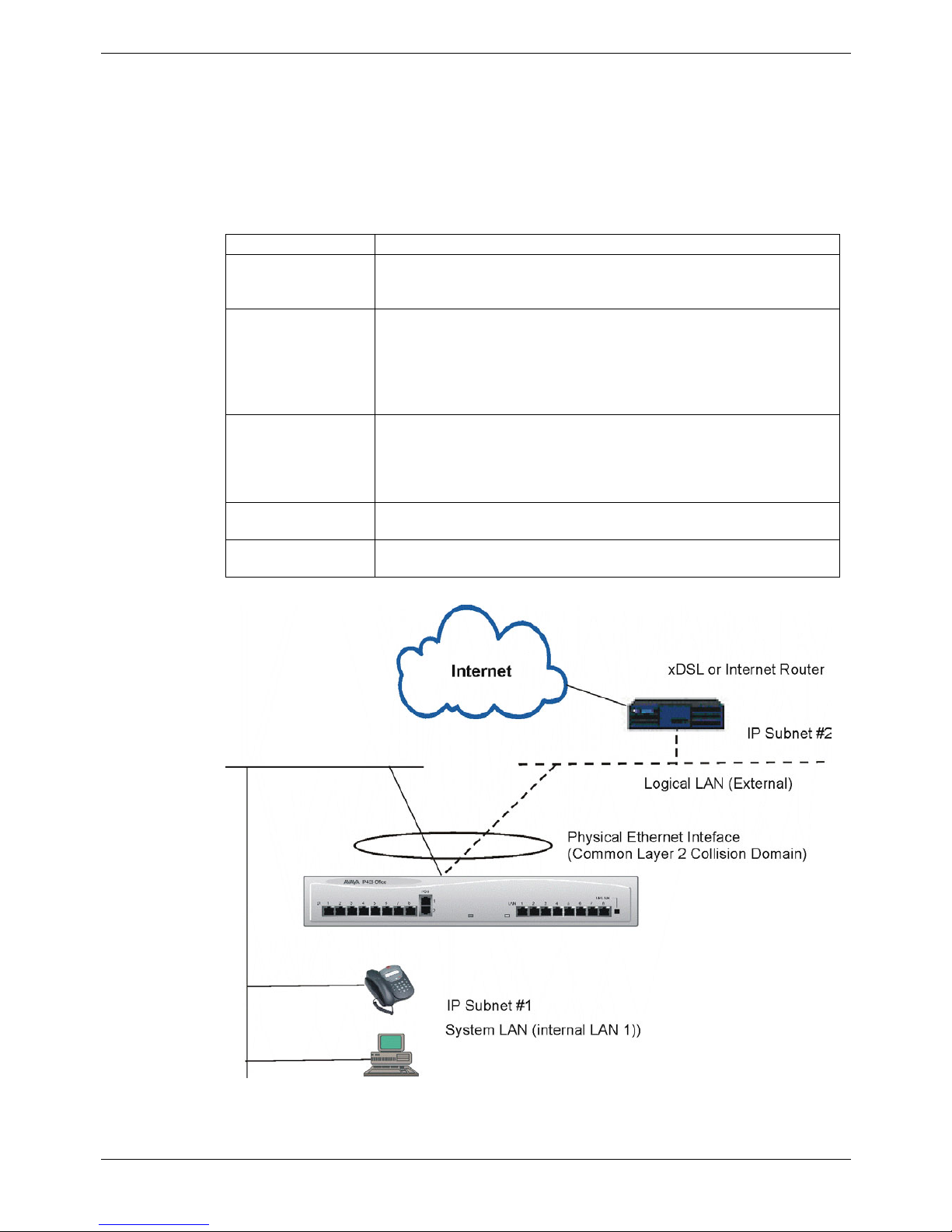
Figure 7. Logical LAN Implementation
IP Office (R3.0) Virtual Private Networking Overview of Secure VPN Implementation - Page 13
40DHB0002UKER Issue 3 (4th February 2005) Logical LAN Implementation

Page 14 - Overview of Secure VPN Implementation
The Logical and System LAN interfaces use different MAC addresses, function on a
common Layer 2 collision domain but operate on separate Layer 3 subnets. Both the
Logical and System LANs are tied to a same Physical LAN
The Logical LAN feature allows single LAN systems such as the IP403 and IP406 to be
used in conjunction with an external Internet router or xDSL device. The feature allows
single LAN systems to operate external and internal IP subnets in support of VPN
networking
NAT functionality is applied to traffic from LAN1 using the IP address assigned to the
Logical LAN. This and other Logical LAN facilities are detailed in the Public Interface
section (see page 17). In addition, an example of the use of a Logical LAN can be seen
on page 34.
For dual LAN systems the second Physical LAN interface (LAN2) should be used as
the Public (External) LAN interface.
Page 14 - Overview of Secure VPN Implementation IP Office (R3.0)
Logical LAN Implementation 40DHB0002UKER Issue 3 (4th February 2005)
Overview of Secure VPN Implementation - Page 15
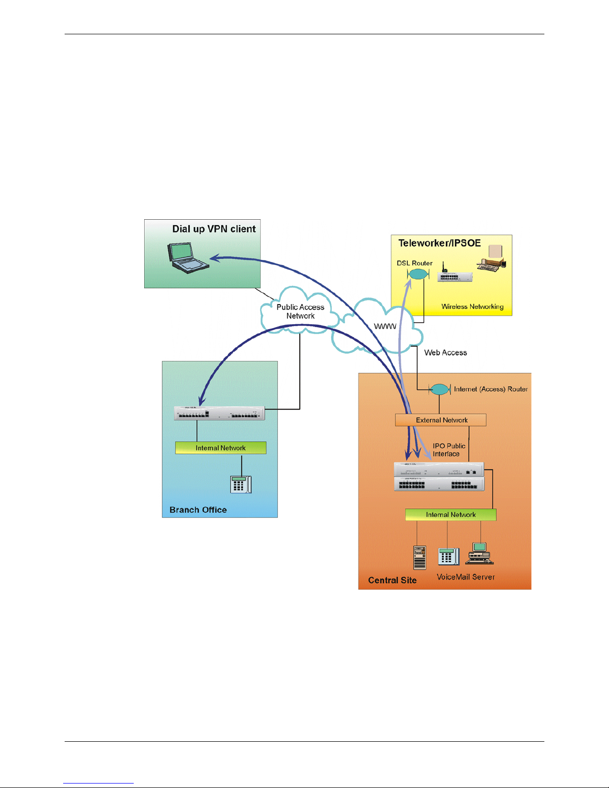
Typical VPN Deployment
The diagram below shows a typical IP Office VPN networking deployment using the
Internet and other public access network. Within this section the elements that are
detailed in the diagram will be discussed with respect to the IP Office 3.0+ VPN
implementation. The following elements will be discussed:
• Public Access
• Public Interface
• IP Office VPN solutions
• Internal LAN
• VPN Client
• VPN and VoIP
• Maximum Load
Figure 8. IP Office VPN Networking
IP Office (R3.0) Virtual Private Networking Overview of Secure VPN Implementation - Page 15
40DHB0002UKER Issue 3 (4th February 2005) Typical VPN Deployment

Page 16 - Overview of Secure VPN Implementation
Public Access Networks
IP Office can be connected to the Internet or other public networks in a number of
ways. This section details the supported technologies and media types for connection
to public networks.
Media Description
Frame Relay
IP Office supports Frame Relay using PPP or FRF12
fragmentation for interoperability. IP Office supports
common electrical interfaces such as X21, V24 and V35 for
Frame Relay connection.
PPP
IP Office support PPP over a dedicated WAN link using
X21, V24 and V35 electrical interfaces.
PSTN
The PSTN network can be used to access the Internet via
an ISP. IP Office supports both digital and Analogue PSTN
services.
xDSL /Internet Router
xDSL and Internet routers provide shared Internet access
for the business or home user. The xDSL and Internet
Router is a managed connection to the ISP network (CO)
that is terminated on an Ethernet interface on the
customers premises (CPE)
IP Office may be used in conjunction an xDSL or Internet
Router. Both the Logical or the Physical LAN2 interface
(dual LAN systems) can be used to provide Public Interface
functionality as described in the following sections.
Guidelines
1. Generally, for site-to-site VPN using xDSL, it is recommended that the two end
points are sourced from the same service provider.
2. The IP Office VPN secure implementation is such that IP Office concurrently
performs the functions of a NAT enabled gateway as well as terminating and
originating VPN tunnels. This allows IP Office to be used for both Secure VPN
networking between branch offices as well as for NAT access to Internet services.
3. IPSec connections that are not originated or terminated by IP Office cannot be
facilitated through a NAT enabled interface.
Further Reading
The IPsec and L2TP specifications are widely discussed in open forums. The reader is
encouraged to seek a fuller explanation than is provided here. Refer to the Virtual
Private Network Consortium http://www.vpnc.org/terms.html
for further information.
Page 16 - Overview of Secure VPN Implementation IP Office (R3.0)
Typical VPN Deployment 40DHB0002UKER Issue 3 (4th February 2005)

Overview of Secure VPN Implementation - Page 17
Public Interface
A public interface is one that is used to connect IP Office directly to an xDSL or Internet
router and thereby provide Internet access. (A public LAN is sometimes referred to as a
demilitarized zone.) It is the function of the public interface to secure the Internal LAN
from the Internet. IP Office uses a firewall and NAT functionality to afford the necessary
protection on a public interface. A public interface connection is facilitated by the
following IP Office interface types:
• LAN2
• Logical LAN
• WAN (PPP numbered)
The IP Office product family includes both single and dual interface systems as follows:
Single interface - IP403 and IP406: For single LAN systems a Logical LAN must be
used for the configuration of the public interface.
Dual interface - IP 412 and IP Office Small Office Edition (IPSOE): For dual LAN
systems the physical LAN2 interface is available and should be
used as the public (external) LAN interface.
The following table summarizes the feature support for these public interface types:
Feature
IP412
IP406
IP403
IPSOE
Description
Firewall √ √ √ √ IP Office Integral Firewall
Logical LAN X √ √ X
For single LAN systems a Logical LAN is a secondary
interface which is created on the physical LAN1
interface.
LAN2 √ X X √ The LAN2 is a second physical Ethernet interface.
NAT √ √ √ √
NAT allows multiple devices to communicate using a
single IP address.
NAT
Reverse
Translation
√ x x √
The function that allows an unknown incoming IP
session to be mapped to a local internal LAN IP address.
DHCP
Client Mode
√ x x √
IP Office can automatically obtain an IP address from a
DHCP server and add the IP address to the interface.
This function is not supported on a Logical LAN
interface.
H323 √ √ √ √ Originate or terminate H323.
IPSec √ √ √ √ Originate or terminate IPSec.
L2TP √ √ √ √ Originate or terminate L2TP.
Guidelines
1. DHCP client mode is not supported on the Logical LAN interface
2. DHCP client mode automatically adds a default route for Internet operation
3. RIP is not supported for IP Office secure VPN networking
4. For a PPP numbered WAN link:
a.
QOS is applied to VOIP traffic destined for VPN tunnel traffic before the
encryption stage.
b.
A minimum bandwidth of between 1-2 Mbps is required for the link between the
two systems is recommended.
c. Do not run Multilink / QOS or IPHC on a WAN link that is passing VPN traffic.
d. The QoS characteristics of IPO VoIP implementation is shown below:
Description Value
Voice UDP port numbers range OxC000 to 0xCFFF
Signalling TCP port number 1720
DSCP (TOS/Diffserv) value OXB8
IP Office (R3.0) Virtual Private Networking Overview of Secure VPN Implementation - Page 17
40DHB0002UKER Issue 3 (4th February 2005) Typical VPN Deployment

Page 18 - Overview of Secure VPN Implementation
Internal LAN
An Internal LAN or private Internet is a secure networking area that has Internet access
but is protected from the Internet by an external or “demilitarized zone”. Typically an
internal LAN will use a private IP addressing scheme. The Internet Assigned Numbers
Authority (IANA) has reserved the following three blocks of the IP address space for
private internets:
10.0.0.0 - 10.255.255.255 (10/8 prefix)
172.16.0.0 - 172.31.255.255 (172.16/12 prefix)
192.168.0.0 - 192.168.255.255 (192.168/16 prefix)
The pertinent IP Office features and function for VPN networking that relate to the
Internal LAN are summarized in this section.
Feature Description
DHCP Server
IP Office can perform the functions of a DHCP server for the
Local LAN attached devices.
Wireless Networking
IP Office Small Office Edition supports 802.11b for wireless
networking.
Telephony
Extensive and proven telephony features including Small
Community Networking allow VPN wide virtual PABX .
Client VPN
A VPN client application is used to initiate secure VPN tunnels from a personal
computer (PC) or notebook to a secure gateway. A VPN client application can be used,
for example, to secure remote dial up connection over the Internet to the corporate
office. Once the VPN client connection is established the PC and user application can
be used transparently. Using MS-Windows, once the IPSec connection has been
established an L2TP connection can then be established over the IPSec VPN. The IP
Office Phone Manger Pro application can be used in conjunction with the supported
VPN clients for secure VoIP transmission over the Internet.
IP Office running 3.0 software supports dynamic VPN endpoints. The dynamic VPN
Tunnel support allows a VPN connection to be established in the instance where the
VPN client IP address is unknown. This is the case for example when the Client VPN is
initiated from a PC on a dialup ISP connection. Typically, in a dialup ISP connection, IP
addresses are allocated only for the duration of the connection.
When configuring a dynamic tunnel endpoint on IP Office the same IPsec configuration
form and hence the same password is used to facilitate all such remote users
Guidelines
1. Certificate Authority (CA) authentication is not supported for IPSec.
2. When using the generic Windows environment for IPSec, client operation uses the
Microsoft Management Console (MMC) to add the IP Security Policy management
snap-in. A windows register key change is required in order to support IPSec in preshared mode. To avoid this requirement, Avaya recommends the use of the
NetScreen VPN client.
3. When configuring multiple Dynamic tunnels all such tunnels are supported by a
single IPSec configuration instance (all remote users share the same pre-shared
secret).
Page 18 - Overview of Secure VPN Implementation IP Office (R3.0)
Typical VPN Deployment 40DHB0002UKER Issue 3 (4th February 2005)
 Loading...