

Avaya Communication Manager IP DECT, IP DECT Installation, Administration And Maintenance Manual
Page 1

Avaya Communication Manager
Avaya IP DECT Installation,
Administration, and Maintenance
16-601625
Issue 1
August 2006
Page 2

© 2006 Avaya Inc.
All Rights Reserved.
Notice
While reasonable efforts were made to ensure that the infor mation in this
document was complete and accurate at the time of printing, Avaya Inc. can
assume no liability for any errors. Changes and corrections to the information
in this document may be incorporated in future releases.
For full support information, please see the complete document,
Avaya Support Notices for Software Documentation, document number
03-600758.
To locate this document on our Web site, simply go to
http://www.avaya.com/support
the search box.
Documentation disclaimer
Avaya Inc. is not responsible for any modifications, addition s, or deletions to
the original published version of this documentation unless such modifications,
additions, or deletions were performed by Avaya. Customer and/or End User
agree to indemnify and hold harmless Avaya, Avaya's agents, servants and
employees against all claims, lawsuits, demands and judgments arising out of,
or in connection with, subsequent modifications, additions or deletions to this
documentation to the extent made by the Customer or End User.
Link disclaimer
Avaya Inc. is not responsible for the contents or reliability of any linked Web
sites referenced elsewhere within this documentation, and Avaya does not
necessarily endorse the products, services, or informa tion described or o ff ered
within them. We cannot guarantee that these links will work all of the time and
we have no control over the availability of the linked pages.
Warranty
Avaya Inc. provides a limited warranty on this product. Refer to your sales
agreement to establish the terms of the limited warran ty. In addition, Avaya’s
standard warranty language, as well as information regarding support for this
product, while under warranty, is available through the following Web site:
http://www.avaya.com/support
Copyright
Except where expressly stated otherwise, the Product is protected by copyrigh t
and other laws respecting proprietary rights. Unauthorized reproduction,
transfer, and or use can be a criminal, as well as a civil, offense un der the
applicable law.
Avaya support
Avaya provides a telephone number for you to use to report pro blems or t o ask
questions about your product. The support telephone number
is 1-800-242-2121 in the United States. For additional support telephone
numbers, see the Avaya Web site: http://www.avaya.com/support
and search for the document number in
.
.
Page 3

Contents
Chapter 1: Overview. . . . . . . . . . . . . . . . . . . . . . . . . . . . . 7
Purpose. . . . . . . . . . . . . . . . . . . . . . . . . . . . . . . . . . . . . . . . . 7
Abbreviations and Definitions . . . . . . . . . . . . . . . . . . . . . . . . 7
References . . . . . . . . . . . . . . . . . . . . . . . . . . . . . . . . . . . 9
Chapter 2: Introduction . . . . . . . . . . . . . . . . . . . . . . . . . . . 11
About the Avaya IP DECT Solution. . . . . . . . . . . . . . . . . . . . . . . . . . 11
About the IP DECT base stations. . . . . . . . . . . . . . . . . . . . . . . . . . . 12
Avaya DECT Mobility Manager . . . . . . . . . . . . . . . . . . . . . . . . . . . . 13
IP signalling and media stream. . . . . . . . . . . . . . . . . . . . . . . . . . . . 14
IP DECT base station Synchronisation. . . . . . . . . . . . . . . . . . . . . . . . 17
IP DECT base station channel capacity . . . . . . . . . . . . . . . . . . . . . . . 20
About the Handsets . . . . . . . . . . . . . . . . . . . . . . . . . . . . . . . . . . 20
About Licensing . . . . . . . . . . . . . . . . . . . . . . . . . . . . . . . . . . . . 21
System Capacities. . . . . . . . . . . . . . . . . . . . . . . . . . . . . . . . . . . 22
Chapter 3: Installation and Configuration . . . . . . . . . . . . . . . . . 23
Avaya IP DECT system start up. . . . . . . . . . . . . . . . . . . . . . . . . . . . 23
Startup of the IP DECT base stations . . . . . . . . . . . . . . . . . . . . . . 23
Booting Overview . . . . . . . . . . . . . . . . . . . . . . . . . . . . . . . 24
Startup of Avaya IP DECT Mobility Manager. . . . . . . . . . . . . . . . . . . 24
ADMM in IP DECT base station mode . . . . . . . . . . . . . . . . . . . . 24
ADMM in Host-Mode. . . . . . . . . . . . . . . . . . . . . . . . . . . . . . 24
Installing the ADMM software. . . . . . . . . . . . . . . . . . . . . . . . . 25
Configure Start Parameter . . . . . . . . . . . . . . . . . . . . . . . . . . 25
To maintain the running ADMM on PC . . . . . . . . . . . . . . . . . . . . 26
Booter . . . . . . . . . . . . . . . . . . . . . . . . . . . . . . . . . . . . . . . 26
Booter versions . . . . . . . . . . . . . . . . . . . . . . . . . . . . . . . . 26
DHCP client. . . . . . . . . . . . . . . . . . . . . . . . . . . . . . . . . . . 26
DHCP REQUEST . . . . . . . . . . . . . . . . . . . . . . . . . . . . . . . . 27
DHCP OFFER. . . . . . . . . . . . . . . . . . . . . . . . . . . . . . . . . . 27
Retries . . . . . . . . . . . . . . . . . . . . . . . . . . . . . . . . . . . . . 28
TFTP client . . . . . . . . . . . . . . . . . . . . . . . . . . . . . . . . . . . 28
Application . . . . . . . . . . . . . . . . . . . . . . . . . . . . . . . . . . . . . 28
Booter update . . . . . . . . . . . . . . . . . . . . . . . . . . . . . . . . . 29
Mandatory options. . . . . . . . . . . . . . . . . . . . . . . . . . . . . . . 29
Optional options . . . . . . . . . . . . . . . . . . . . . . . . . . . . . . . . 30
IP DECT base station LED Status. . . . . . . . . . . . . . . . . . . . . . . . . 31
State graph of the start up phases . . . . . . . . . . . . . . . . . . . . . . . . 32
Issue 1 August 2006 3
Page 4

Contents
Static local configuration of the IP DECT base station . . . . . . . . . . . . . . . 33
802.1Q Support . . . . . . . . . . . . . . . . . . . . . . . . . . . . . . . . . . . . 35
Avaya DECT Mobility Manager Requirements. . . . . . . . . . . . . . . . . . 35
ADMM running on an IP DECT base station . . . . . . . . . . . . . . . . . 35
ADMM running on a Linux Server . . . . . . . . . . . . . . . . . . . . . . 36
Principles and Parameter . . . . . . . . . . . . . . . . . . . . . . . . . . . . . 36
Why not VLAN ID 0 . . . . . . . . . . . . . . . . . . . . . . . . . . . . . . . . 36
VLAN and the Boot Phase of a IP DECT base station. . . . . . . . . . . . . . 36
DHCP . . . . . . . . . . . . . . . . . . . . . . . . . . . . . . . . . . . . . . 36
Local configuration of the IP DECT base stations. . . . . . . . . . . . . . 37
Configuring the Avaya DECT Mobility Manager . . . . . . . . . . . . . . . . . . . 37
Service Login procedure . . . . . . . . . . . . . . . . . . . . . . . . . . . . . 38
Licensing. . . . . . . . . . . . . . . . . . . . . . . . . . . . . . . . . . . . . . 40
Definition of the License IP DECT base stations . . . . . . . . . . . . . . 40
Get and add the License Key and PARK number . . . . . . . . . . . . . . 41
System . . . . . . . . . . . . . . . . . . . . . . . . . . . . . . . . . . . . . . . 42
System settings . . . . . . . . . . . . . . . . . . . . . . . . . . . . . . . . 42
Rebooting the ADMM . . . . . . . . . . . . . . . . . . . . . . . . . . . . . 44
User Account. . . . . . . . . . . . . . . . . . . . . . . . . . . . . . . . . . 44
Time zones . . . . . . . . . . . . . . . . . . . . . . . . . . . . . . . . . . . 45
SNMP . . . . . . . . . . . . . . . . . . . . . . . . . . . . . . . . . . . . . . 46
Backup . . . . . . . . . . . . . . . . . . . . . . . . . . . . . . . . . . . . . 48
IP Regions . . . . . . . . . . . . . . . . . . . . . . . . . . . . . . . . . . . . . 49
IP DECT base station Configuration . . . . . . . . . . . . . . . . . . . . . . . 50
DECT configuration . . . . . . . . . . . . . . . . . . . . . . . . . . . . . . 51
States of an IP DECT base station . . . . . . . . . . . . . . . . . . . . . . 52
IP Trunks . . . . . . . . . . . . . . . . . . . . . . . . . . . . . . . . . . . . . . 53
Configuration of IP DECT handsets . . . . . . . . . . . . . . . . . . . . . . . 55
System Features. . . . . . . . . . . . . . . . . . . . . . . . . . . . . . . . . . 59
Voice Mail . . . . . . . . . . . . . . . . . . . . . . . . . . . . . . . . . . . 59
Media Server System Features . . . . . . . . . . . . . . . . . . . . . . . . 60
Digit Treatment . . . . . . . . . . . . . . . . . . . . . . . . . . . . . . . . 61
Corporate Directory . . . . . . . . . . . . . . . . . . . . . . . . . . . . . . 61
TFTP based Corporate Directory . . . . . . . . . . . . . . . . . . . . . . . 64
WML . . . . . . . . . . . . . . . . . . . . . . . . . . . . . . . . . . . . . . 65
Chapter 4: Avaya Communication Manager . . . . . . . . . . . . . . . . 67
Usage and Important Notes. . . . . . . . . . . . . . . . . . . . . . . . . . . . . . 67
ACM system administration. . . . . . . . . . . . . . . . . . . . . . . . . . . . . . 67
4 Avaya IP DECT Installation, Administration, and Maintenance
Page 5

Chapter 5: Functional description . . . . . . . . . . . . . . . . . . . . . 73
Registration of Avaya 3701 and Avaya 3711 . . . . . . . . . . . . . . . . . . . . . 73
WML . . . . . . . . . . . . . . . . . . . . . . . . . . . . . . . . . . . . . . . . . . 73
Pre-configured URL . . . . . . . . . . . . . . . . . . . . . . . . . . . . . . . . 73
User Input of URLs . . . . . . . . . . . . . . . . . . . . . . . . . . . . . . . . 74
Corporate Directory . . . . . . . . . . . . . . . . . . . . . . . . . . . . . . . . 74
LDAP based Corporate Directory. . . . . . . . . . . . . . . . . . . . . . . . . 74
TFTP based Corporate Directory . . . . . . . . . . . . . . . . . . . . . . . . . 75
Message Waiting Indication for the 20DT Handset . . . . . . . . . . . . . . . . . 76
Avaya system . . . . . . . . . . . . . . . . . . . . . . . . . . . . . . . . . . . 76
Avaya DECT Mobility Manager . . . . . . . . . . . . . . . . . . . . . . . . . . 77
Message sequence chart . . . . . . . . . . . . . . . . . . . . . . . . . . . . . 78
Configuration . . . . . . . . . . . . . . . . . . . . . . . . . . . . . . . . . . . 78
Chapter 6: Maintenance. . . . . . . . . . . . . . . . . . . . . . . . . . . 79
Booter . . . . . . . . . . . . . . . . . . . . . . . . . . . . . . . . . . . . . . . . . 79
Checking the IP DECT base station Booter Version . . . . . . . . . . . . . . 79
Manual Update of the IP DECT base station Booter. . . . . . . . . . . . . . . 80
Static local configuration . . . . . . . . . . . . . . . . . . . . . . . . . . . . . . . 80
Checking the local configuration. . . . . . . . . . . . . . . . . . . . . . . . . 80
Removing the local configuration . . . . . . . . . . . . . . . . . . . . . . . . 81
Contents
Avaya 3701 Firmware . . . . . . . . . . . . . . . . . . . . . . . . . . . . . . . . . 81
Checking the Avaya 3701 Firmware Version. . . . . . . . . . . . . . . . . . . 81
Upgrading the Avaya 3701 Firmware. . . . . . . . . . . . . . . . . . . . . . . 82
Avaya 3711 maintenance and diagnostic . . . . . . . . . . . . . . . . . . . . . . 85
Avaya 3711 Auto Call Test Mode . . . . . . . . . . . . . . . . . . . . . . . . . 85
Avaya 3711 Auto Answer Test Mode . . . . . . . . . . . . . . . . . . . . . . . 86
Avaya 3711 Site Survey Mode . . . . . . . . . . . . . . . . . . . . . . . . . . 87
Avaya 3711 Master Reset . . . . . . . . . . . . . . . . . . . . . . . . . . . . . 87
Change the Avaya 3711 Security PIN. . . . . . . . . . . . . . . . . . . . . . . 88
Avaya 3711 Firmware . . . . . . . . . . . . . . . . . . . . . . . . . . . . . . . . . 88
Checking the Avaya 3711 Firmware Version. . . . . . . . . . . . . . . . . . . 88
Upgrading the Avaya 3711 Firmware. . . . . . . . . . . . . . . . . . . . . . . 89
Site Survey Measurement Equipment . . . . . . . . . . . . . . . . . . . . . . . . 92
Diagnostic . . . . . . . . . . . . . . . . . . . . . . . . . . . . . . . . . . . . . . . 93
Syslog . . . . . . . . . . . . . . . . . . . . . . . . . . . . . . . . . . . . . . . 93
Telnet user shell . . . . . . . . . . . . . . . . . . . . . . . . . . . . . . . . . . 94
Login . . . . . . . . . . . . . . . . . . . . . . . . . . . . . . . . . . . . . . 95
Command overview . . . . . . . . . . . . . . . . . . . . . . . . . . . . . . 95
Issue 1 August 2006 5
Page 6

Contents
IP DECT base station console commands . . . . . . . . . . . . . . . . . . 96
ADMM console commands . . . . . . . . . . . . . . . . . . . . . . . . . . 97
SNMP . . . . . . . . . . . . . . . . . . . . . . . . . . . . . . . . . . . . . . . . 97
DECT Monitor of the Avaya IP DECT System . . . . . . . . . . . . . . . . . . 98
Appendix A: Appendix . . . . . . . . . . . . . . . . . . . . . . . . . . . 103
Supported Codecs and Codec negotiation . . . . . . . . . . . . . . . . . . . . . 103
MIB-II . . . . . . . . . . . . . . . . . . . . . . . . . . . . . . . . . . . . . . . . . . 104
system (1) . . . . . . . . . . . . . . . . . . . . . . . . . . . . . . . . . . . . . 104
interfaces (2) . . . . . . . . . . . . . . . . . . . . . . . . . . . . . . . . . . . . 105
at (3) . . . . . . . . . . . . . . . . . . . . . . . . . . . . . . . . . . . . . . . . 108
ip (4) . . . . . . . . . . . . . . . . . . . . . . . . . . . . . . . . . . . . . . . . 108
icmp (5) . . . . . . . . . . . . . . . . . . . . . . . . . . . . . . . . . . . . . . . 113
tcp (6) . . . . . . . . . . . . . . . . . . . . . . . . . . . . . . . . . . . . . . . . 115
udp (7) . . . . . . . . . . . . . . . . . . . . . . . . . . . . . . . . . . . . . . . 117
egp (8) . . . . . . . . . . . . . . . . . . . . . . . . . . . . . . . . . . . . . . . 118
cmot (9). . . . . . . . . . . . . . . . . . . . . . . . . . . . . . . . . . . . . . . 118
transmission (10) . . . . . . . . . . . . . . . . . . . . . . . . . . . . . . . . . 118
snmp (11). . . . . . . . . . . . . . . . . . . . . . . . . . . . . . . . . . . . . . 119
WML Tags and Attributes supported. . . . . . . . . . . . . . . . . . . . . . . . . 121
Detailed overview:
Avaya IP Phones and the ADMM/Avaya 3711. . . . . . . . . . . . . . . . . . . . 122
Protocols and Ports used by Avaya IP DECT System. . . . . . . . . . . . . . . . 125
6 Avaya IP DECT Installation, Administration, and Maintenance
Page 7

Chapter 1: Overview
Purpose
This document describes the installation and administration of the Avaya IP DECT solution
using Avaya DECT Mobility Manager version 1.x.x.
Abbreviations and Definitions
Abbreviations
AC Authentication Code
ACM Avaya Communication Manager
ADMM Avaya IP DECT Mobility Manager
ADPCM Adaptive Differential Pulse Code Modulation
CM Communication Manager
DECT Digital Enhanced Cordless
Telecommunication
DHCP Dynamic Host Configuration Protocol
DSP Digital Signal Processor
GAP Generic Access Profile
IPEI International Portable Equipment Identity
IP Base Station IP DECT Base Station
HTTP Hyper Text Transfer Protocol
MSSF Media Server System Features
OMM Open Mobility Manager (same as ADMM)
PARK Portable Access Rights Key
PP Portable Part (same as IP DECT handset)
RFP Radio Fixed Part (same as IP Base Station)
RTCP Real Time Control Protocol
Issue 1 August 2006 7
Page 8

Overview
Definitions
RTP Real Time Protocol
TFTP Trivial File Transfer Protocol
VLAN Virtual Local Area Network
DECT Digital Enhanced Cordless Telecommunication
● The standard (ETS 300 175) essentially specifies the
air interface, known as the radio interface. Voice and
data can both be transmitted via this interface.
● Its key technical characteristics are:
- Frequency range: approx. 1,880 – 1,900 GHz
(approx. 20 MHz bandwidth)
- 10 carrier frequencies (1,728 MHz spacing) with 12
time slots each *)
- Doubling the number of time slots (to 24) using the
TDMA process
- Net data rate per channel of 32 kbit/s (for voice
transmission using ADPCM)
- Voice coding using the ADPCM method
- Maximum transmission power of 10 mW
GAP Generic Access Profile
● GAP is the abbreviation for Generic Access Profile
● The GAP standard (ETS 300 444) is based on the
same technology as DECT, but is limited to the most
important basic features. This standard was created in
order to allow telephones of different vendors to be
used on any type of DECT system. It thus represents
the smallest common denominator of all
manufacturer-specific variants of the DECT standard.
● An important limitation in the GAP standard is that
external handover is not possible. For this reason
connection handover is used, which is supported by
GAP terminals.
● The operation of GAP-capable telephones is
comparable to that of analogue terminals. For e xample,
features can be called up via ‘*’ and ‘#’ procedures.
Handover Handover
A handover is similar to roaming, but occurs during an
ongoing call. A handover normally takes place ”in the
background,” without disrupting the call (seamless handover).
8 Avaya IP DECT Installation, Administration, and Maintenance
Page 9

IPEI International Portable Equipment Identity
● 13-digit identification code for telephones
● Example: 00019 0592015 3 (the final digit is the
checksum).
● The code is represented in decimal form.
● This code is globally unique.
PARK Portable Access Rights Key
Access code for the handset. This code determines whether a
telephone can access a particular DECT system. Used for
unique selection of the system at enrolment.
Handover DECT base station networking
While in motion, the telephone performs ongoing
measurements to determine which base station is best
received. The one that can be best received is defined as the
active base station. To prevent the telephone from rapidly
switching back and forth between two base stations that can
be almost equally well received, certain threshold values are
in effect. (similar to a Schmitt trigger circuit )
Purpose
References
1. The TFTP Protocol (Revision 2), RFC 1350, July 1992
2. Avaya – Open Mobility configuration settings; KI CTB006259
3. Product Requirements and System Architecture; Integrating DeTeWe IP DECT wireless into
Avaya Multi Vantage Solution utilising an IP infrastructure
4. Product Requirements and System Architecture; Integrating DeTeWe IP DECT wireless into
Avaya IP Office utilising an IP infrastructure
5. RFC 1156, Management Information Base for Network Management of TCP/IP-based
internets, May 1990
6. RFC 1213, Management Information Base for Network Management of TCP/IP-based
internets: MIB-II, March 1991
7. RFC 1450, Management Information Base for version 2 of the Simple Network
Management Protocol (SNMPv2), April 1993
8. http://www.simpleweb.org/ietf/mibs/index.html?sel=IETF
9. Avaya 3711 User Guide
10. Avaya 3701 User Guide
11. Avaya IP Telephone LAN Administrators Guide
Issue 1 August 2006 9
Page 10

Overview
10 Avaya IP DECT Installation, Administration, and Maintenance
Page 11
Chapter 2: Introduction
About the Avaya IP DECT Solution
The DECT over IP system comprises the following components :
● IP DECT Base Stations distributed over an IP network and offering DECT as a wireless
interface.
● ACM Media Server/Media Gateway as telephony system platforms
● DECT telephone: Avaya 3701 and Avaya 3711 wireless phones
● Avaya DECT Mobility Manager (ADMM): management interface for IP DECT Solution,
which runs on either one of the IP DECT Base stations or on a dedicated LINUX server
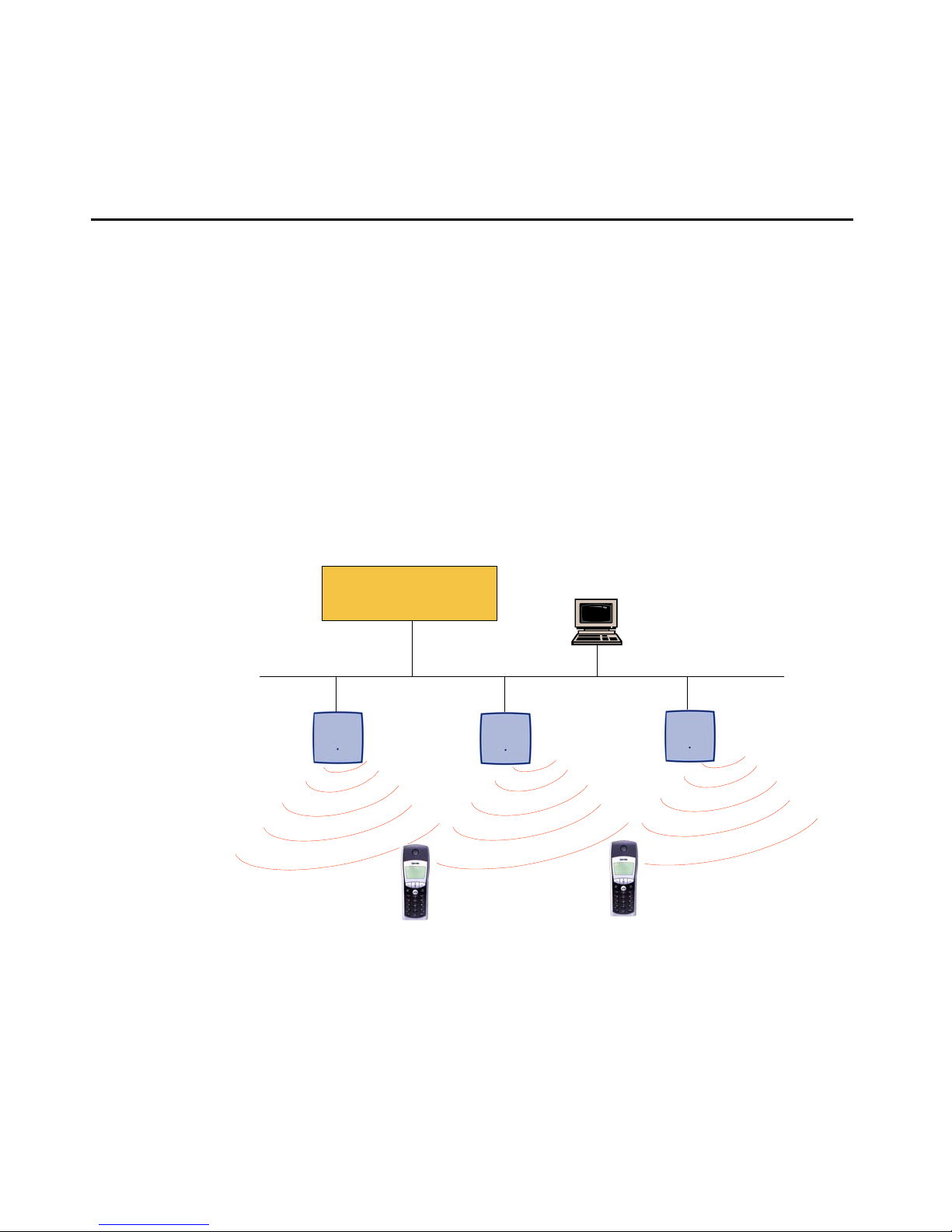
The following pictures give a graphical overview of the architecture of the Avaya IP DECT
solution:
Media Server
Media Gateway
Web B rowser for
administration purposes
IP DECT Base
Stations
256 max.
The Media Server, Media Gateway, ADMM and the IP DECT base stations communicate
through the IP infrastructure. The IP DECT base stations and the IP DECT handsets
communicate over air, where the DECT GAP protocol is used or DECT GAP with proprietary
enhancements.
Issue 1 August 2006 11
Page 12

Introduction
About the IP DECT base stations
All IP DECT base stations have the same hardware and software capabilities.
One of the IP DECT base stations within an IP DECT installation may be chose n to opera te not
in the IP DECT base station only mode but in the Avaya DECT Mobility Manager (ADMM)
mode. During installation, you will set one of the IP DECT base stations to ADMM mode, or you
will use a dedicated LINUX server running as an ADMM. The others are in the IP DECT base
station only mode.
IP DECT base station only mode:
Within that mode, the IP DECT base station converts IP protocol to DECT protocol and then
transmits the traffic to and from the Handsets over a DECT timeslot. On air the IP DECT base
station has 12 time slots, eight can have associated DSP resources for media streams, the
remaining four time slots are used for example for control signalling between IP DECT base
stations and the Handsets or for bearer handover.
Groups of IP DECT base stations have to be built which are named Cluste r. Within a Cluster IP
DECT base stations are synchronised to enable a seamless hand over when a user crosses
from one IP DECT base station’s zone of coverage to another. For synchronisation it is not
necessary for an IP DECT base station to communicate directly with all other IP DECT base
stations in the system. Each IP DECT base station only needs to be able to communicate with
the next IP DECT base station in the chain. But it is preferable for an IP DECT base station to
see more than one IP DECT base station to guarantee synchronisation in the event that one of
the IP DECT base stations fails.
The four control signalling channels are also used to carry bearer signals that signal the
Handset to start the hand over process. If the radio signal of another IP DECT base station is
stronger than that of the current IP DECT base station, then the Handset starts the hand over
process to the IP DECT base station that has the stronger signal as the user moves around the
site.
Avaya IP DECT Mobility Manager (ADMM) mode:
In this mode, an IP DECT base station functions as a regular IP DECT base station. Additionally
it is responsible for H.323 signalling between the IP DECT system and the telephony or media
server. Further on it takes management part of the IP-DECT solution. You designate an IP
DECT base station as the ADMM by assigning an IP address to the IP DECT base st ation in the
DHCP scope (see Mandatory options
(see S t atic local configuration of the IP DECT base stat ion
station is designated as the ADMM, it starts the extra services on board (for example, the Web
Service that supports the management interface).
on page 29) or by setting the data via OM Configurator
on page 33). After an IP DECT base
12 Avaya IP DECT Installation, Administration, and Maintenance
Page 13

Avaya DECT Mobility Manager
Note:
Note: It is possible to deactivate the DECT part of a IP DECT base station. If the DECT
Interface is deactivated then the resources (CPU and memory) are available for
the ADMM.
Light emitting diode (LED)
signalling of current operating state on the IP DECT Base Station
Ethernet jack
Power supply in line with Power over LAN™ standard IEEE 802.3af
Power jack (110 V/240 V AC adapter)
Avaya DECT Mobility Manager
The Avaya DECT Mobility Manager (ADMM) performs the following tasks:
● signalling gateway (H.323 <-> DECT GAP)
● media stream management
● manages synch over air functions between IP DECT base stations
● facilitates system configuration modifications
● provides additional services e.g.
- Corporate Directory (LDAP or TFTP based)
- WML browser
The Avaya DECT Mobility Manager (ADMM) may run on on e of the IP DECT base stat ion or on
a dedicated Linux Server.
Issue 1 August 2006 13
Page 14
Introduction
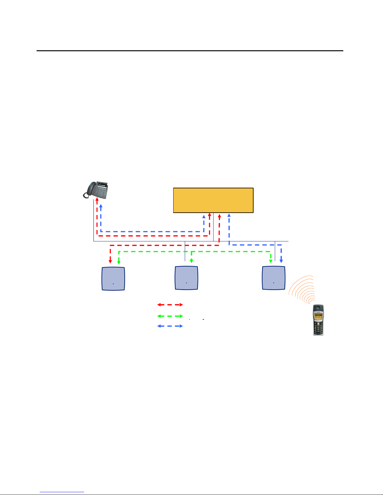
IP signalling and media stream
To establish a call between an IP Phone and an DECT handset, the following IP streams must
be established:
● a signalling channel to and from the IP phone
● a signalling channel to and from the ADMM
● a control interface between the ADMM and the IP DECT base station that has a
connection to the DECT handset (known as the primary IP DECT base station)
a Real Time Protocol (RTP) / Real Time Control Protocol (RTCP) connection between the IP
Phone and the Media Gateway and then a RTP/RTCP connection between the Me dia Gateway
and the IP DECT base station.The following figure illustrates this scenario.
IP-Phone
Media Gateway
Media Server
ADMM
(IP DECT Base Station
in ADMM mode)
Primary Base
Station
Signalling
Base Station Control
RTP/RTCP
14 Avaya IP DECT Installation, Administration, and Maintenance
Page 15
IP signalling and media stream
)
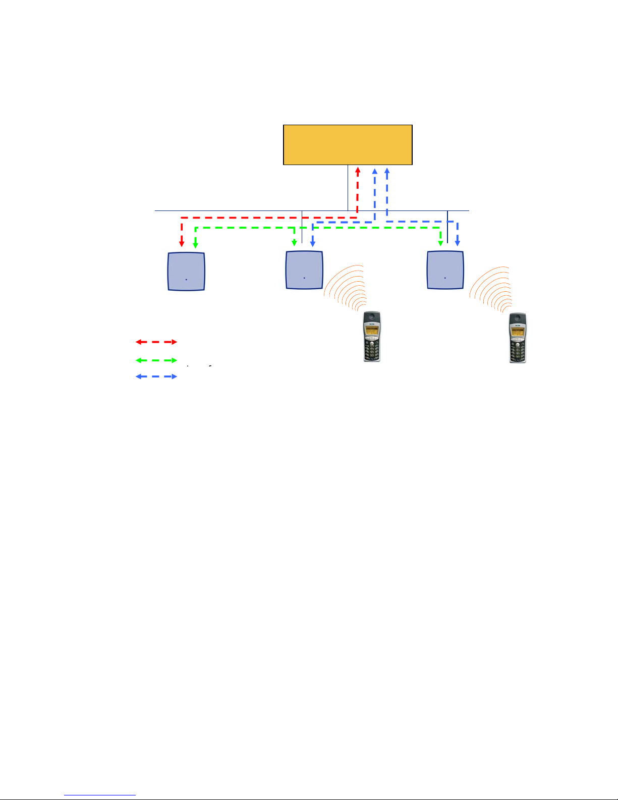
To establish a call between two DECT handsets the same IP streams must be established like
in the scenario before, except the IP phone is not involved. The following figure illustrates this
scenario.
Media Server
Media Gateway
ADMM
(IP DECT Base Station
in ADMM mode
Signalling
Base Station Control
RTP/RTCP
A call from one DECT handset to another that resides on the same IP DECT base station will
loop back within the IP DECT base station, if no Media gateway is involved. So the call will not
pass through to the local area network (LAN). Although the voice packets will not impact LAN
traffic, signal packets will.
It is also be possible to direct the media stream to connect directly the IP phone and the IP
DECT base station, as shown in the following figures.
Issue 1 August 2006 15
Page 16
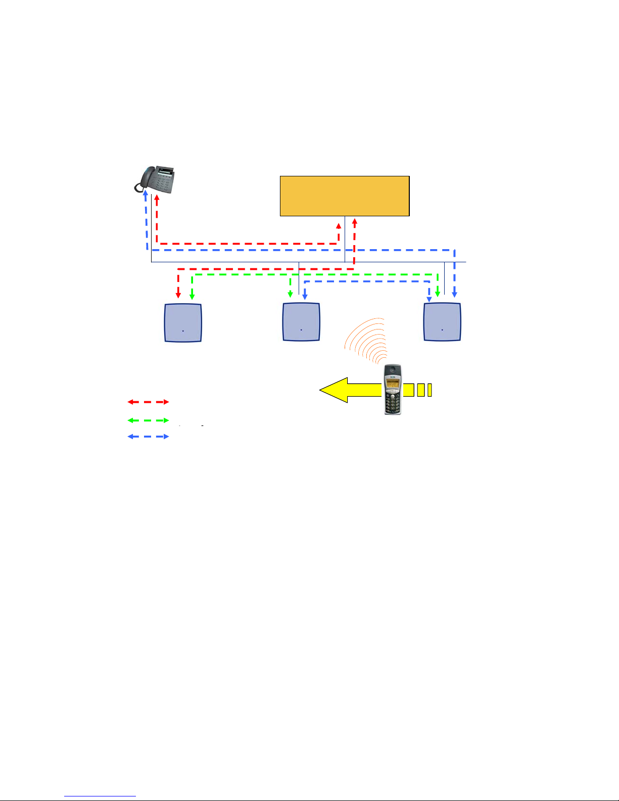
Introduction
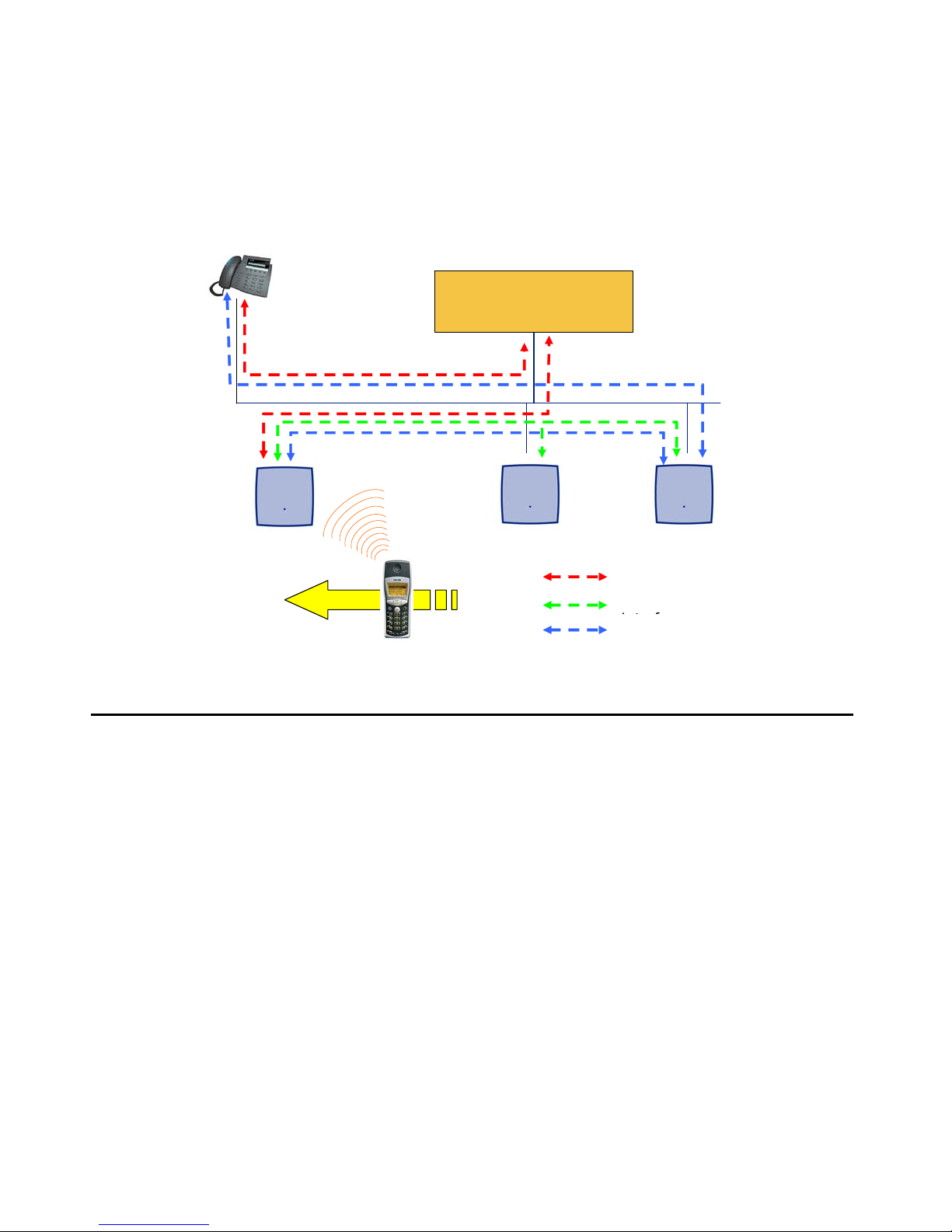
If the DECT handset user is moving, the handset detects that anot her IP DECT base station has
a better signal strength and, therefore, it starts the hand over process. The media stream from
the IP Phone cannot move to the secondary IP DECT base station, so the primary IP DECT
base station uses the LAN to direct the voice to the secondary IP DECT base station, as shown
in the following figure.
IP-Phone
Media Server
Media Gateway
ADMM
(IP DECT Base Station
in ADMM mode)
Signalling
Base Station Control
RTP/RTCP
Secondary Base
Station
Primary Base
Station
16 Avaya IP DECT Installation, Administration, and Maintenance
Page 17
IP DECT base station Synchronisation
As the DECT set user moves into the next IP DECT base station zone of coverage, the DECT
set detects that the IP DECT base station has a better signal strength. Ag ain, the media stream
from the IP phone cannot move to the secondary IP DECT base station, so the primary IP
DECT base station uses the LAN to direct the voice to the new secondary IP DECT base
station.
IP-Phone
Media Server
Media Gateway
New secondary Base
Station
ADMM
(IP DECT Base Station
IP DECT base station Synchronisation
To guarantee a seamless hand over if a caller moves from one IP DECT base station zone of
coverage to another IP DECT base station zone of coverage, an accurate synchronisation of
the IP DECT base stations is necessary.
The IP DECT base stations are synchronised over the air interface. During start-up, one IP
DECT base station will be the first, which transmits a signal on the air. The other IP DECT base
stations only receiving the signal until their are synchronous. If a IP DECT base station gets in
synch then it will transmit a signal on the air and will be the synch source for the next IP DECT
base stations. Only IP DECT base stations which can receive each other will be synchronised.
Primary Base
Station
Signalling
Base Station Control
RTP/RTCP
For the IP DECT base station to sync to another IP DECT base station the signal strength
cannot drop below –70 dBm. You must consider this requirement during the site survey.
Issue 1 August 2006 17
Page 18
Introduction
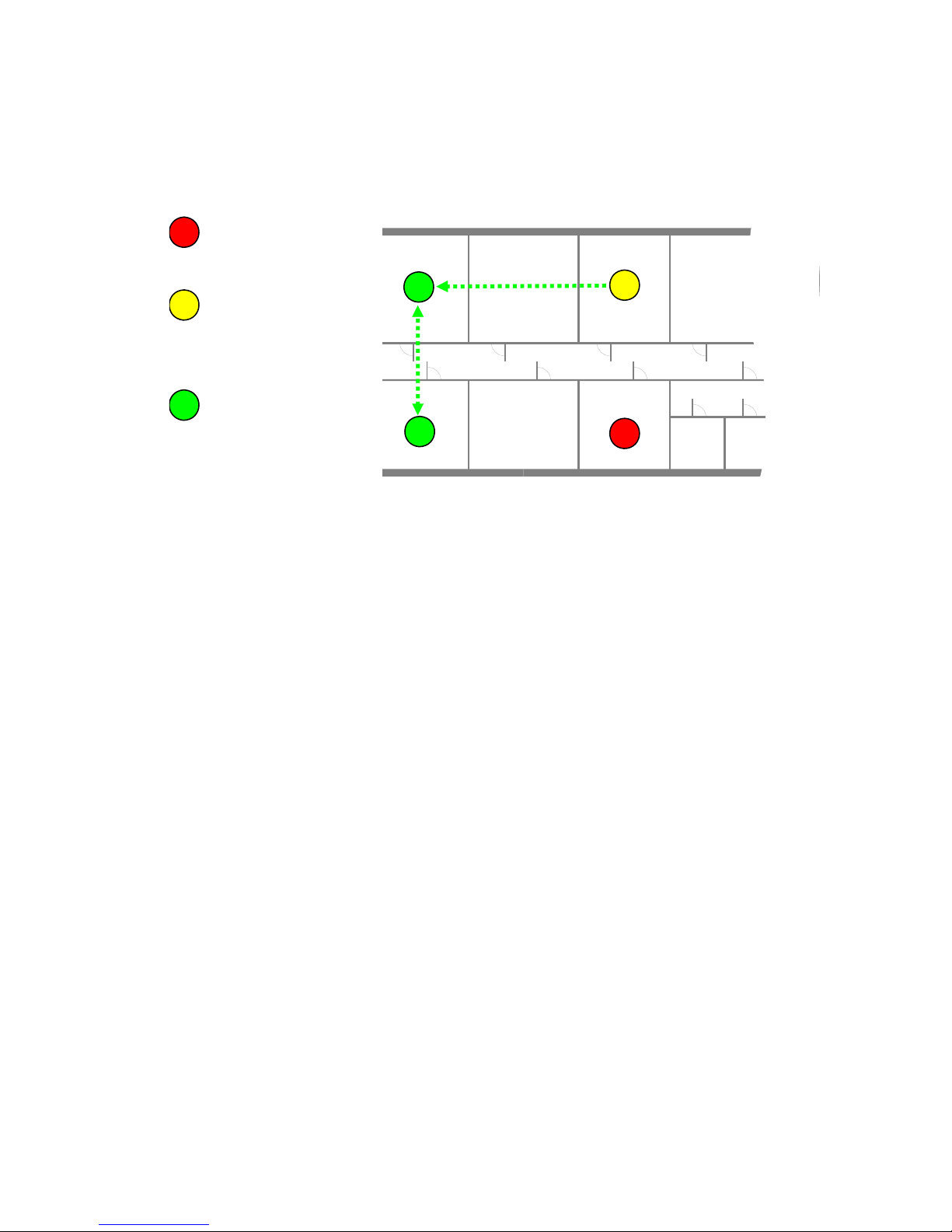
The first active IP DECT base station will be chosen by the ADMM as the Master for the
synchronisation. If a specific IP DECT base station shall be used, for example to speed-up the
synchronisation phase, then a IP DECT base station can be marked with ‘Act as Master during
startup’ on the IP DECT base station Web page.
Unsynchronised RFP,
which does not receive a
R 101 R 102 R 103 R 104 R 105
signal from another RFP
Unsynchronised RFP,
which receives a signal
from another RFP and
tries to get synchronised
Synchronised RFP,
which receives and
transmits a signal on the
air interface
R 111 R 110 R 109 R 108
R 107
R 106
As long as a IP DECT base station is not in synch, no calls can be established using this IP
DECT base station.
If a IP DECT base station loses the synchronisation the IP DECT base station does not accept
new calls ("Busy-Bit"). There is a delay of max. 3 minutes until the active calls on this IP DECT
base station are finished. Then it tries to get synchronised again.
18 Avaya IP DECT Installation, Administration, and Maintenance
Page 19
IP DECT base station Synchronisation
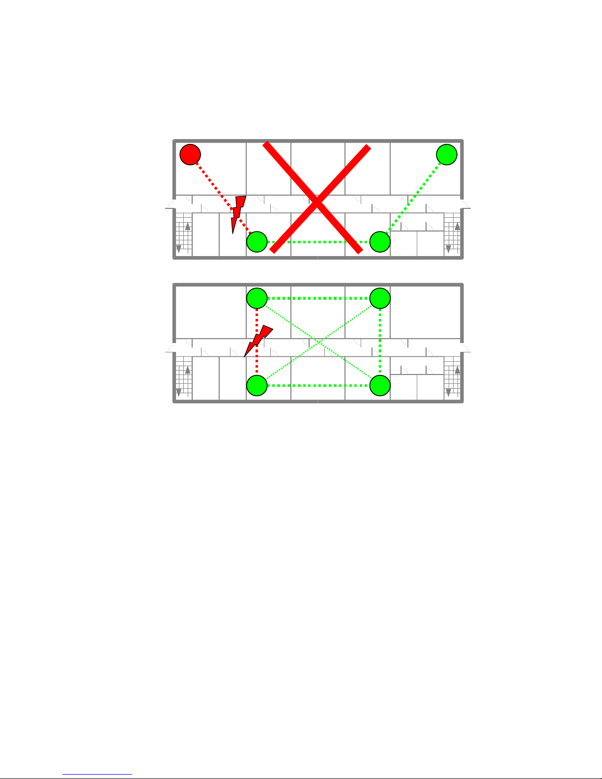
An IP DECT installation is more reliable if a IP DECT base station can receive the signal from
more than only one IP DECT base station, because the other signals are also used for
synchronisation.
Unreliable Installation
R 101 R 102 R 103 R 104 R 105
Don‘t
R 111 R 110 R 109 R 108
R 107
Reliable Installation
R 101 R 102 R 103 R 104 R 105
R 106
R 111 R 110 R 109 R 108
R 107
R 106
The synch-over-air solution is very reliable, because all existing redundant paths are used for
synchronisation. Thus, hardware tolerances have only very little influence. No IP DECT base
station has a key position. Example: If the Initial Master does not start up, another IP DECT
base station will be chosen by the ADMM.
Only unfavourable setups without redundant synchronisation paths can cause problems.
Sometimes IP DECT base stations do not need to be synchronized, e.g. if they are in different
buildings. These IP DECT base stations can be put into different clusters. IP DECT base
stations in different clusters will not be synchronised with each other. Different cluster start up
independent at the same time.
Issue 1 August 2006 19
Page 20

Introduction
IP DECT base station channel capacity
The IP DECT base station has 12 available airtime slots:
● eight can have associated DSP resource for media streams
● the remaining four time slots are used for example for control signalling b etween IP DECT
base stations and the Handsets or for bearer handover
If all eight Media Stream channels are used IP DECT announces a ‘Busy Bit’. In that case the
DECT sets determine whether another IP DECT base station has an appropriate signal
strength. If so, the DECT set will hand over to that IP DECT base station. Once the hand over
has been completed, the IP DECT base station will then lower its Busy Bit.
When ever the busy state is announced a log entry is made to the system logs. If the
announcement of Busy raises in a specific area, a further IP DECT base station should be
installed to double the number of media streams available for calls.
About the Handsets
There are two models of Handsets: the Avaya 3711 and the Avaya 3701. A detailed description
of the two phones an their local features is available with Avaya 3711 User Guide and Avaya
3701 User Guide.
Also Avaya Kirk DECT phones (WT9620 and DT20) and st andard 3
function on the IP DECT solution. But the functionality may be limited by the characteristics of
rd
the 3
administration.
party DECT phone. The 3rd party DECT phones need to provide the IPEI for
rd
party DECT GAP phones
20 Avaya IP DECT Installation, Administration, and Maintenance
Page 21

About Licensing
The ADMM needs to be enabled with a license key, which depends on the MAC address of
some IP DECT base stations in the DECT system. The license key needs to be entered /
administered via the ADMM web administration interface.
There are a sets of licenses with additional upgrade licenses .
● License for 1 IP DECT base station
● License for 2 IP DECT base stations
● License for 3 to 5 IP DECT base stations
● License for more than 5 IP DECT base stations
As mentioned above the license key depends on the MAC addresses of some IP DECT base
stations of the DECT system (License-IP DECT base stations). Each IP DECT base station can
be an License-IP DECT base station independently where the IP DECT base station is located.
The number of IP DECT base station MAC addresses encoded in the license depends on the
size of the DECT installation.
About Licensing
System size
(# of IP DECT base
stations)
Number of IP DECT base station MAC addresses
encoded in the license (License-IP DECT base
stations)
11
22
3 to 5 3
6 or more (6+) 3
Additionally to the MAC addresses the PARK (Portable Access Rights Key), which identifies the
DECT installation, is also by part of the license. Because a DECT system can only be operated
with a valid PARK, a DECT installation without a license will be inactive on the DECT site.
An IP DECT system is operational, if it set up with a license and the IP DECT base stations,
which are encoded in the license are part of the system so that the ADMM can communicate
with these License-IP DECT base stations.
Issue 1 August 2006 21
Page 22

Introduction
Depending on the size of the IP DECT system, it will still work if some License-IP DECT base
stations are out of service.
System size
(# of IP
Number of License-IP DECT
base stations
DECT base
stations)
11 1
22 1
3 to 5 3 2
6 or more
32
(6+)
If the minimum number of License-IP DECT base stations can not be reached by the ADMM or
more IP DECT base stations are administered than licensed the DECT system will block the
voice streams.
System Capacities
There is only one Avaya DECT Mobility Manager (ADMM) in the system. The capacities are
depending on the platform, the ADMM is running on.
Number of License-IP DECT base
stations available at minimum
ADMM running on a IP DECT base station:
● up to 256 IP DECT base stations can be controlled
● up to 400 handsets are handled
● up to 100 handsets can be active simultaneously
It is possible to deactivate the DECT part of a IP DECT base station. If the DECT Interface is
deactivated then the resources (CPU and memory) are available for the ADMM only.
ADMM running on a Linux Server:
● up to 256 IP DECT base stations can be controlled
● up to 16.320 handsets are handled
● up to 1500 handsets can be active simultaneously (theoretical maximum is 2048 but this is
not practical because of handovers)
22 Avaya IP DECT Installation, Administration, and Maintenance
Page 23

Chapter 3: Installation and Configuration
To establish and maintain a IP DECT installation, a network infrastructure is assumed, which
comprises at least the following components:
● IP DECT base stations, IP DECT handsets and ACM Media Server
● a Redhat Enterprise 4.0 ES Linux Server, if it is decided not to run the Avaya DECT
Mobility Manager on a IP DECT base station
● a TFTP Server
Depending on the operational modes the following services should be provided:
● DHCP
● SNTP
● DNS
● WML/HTTP
● LDAP
● Syslog daemon
Avaya IP DECT system start up
Startup of the IP DECT base stations
For booting an IP DECT base station there must at least a TFTP-Server on the attached
network to load the application software.
The essential network settings can be given alternatively
● given by a DHCP Server at startup time.
● can be configured on the IP DECT base station with the tool OM-Configurator. The
settings made by OM-Configurator will be saved permanently in the internal flash memory.
The IP DECT base station gets the boot image file from a TFTP server. The used TFTP server
needs to support RFC 1350, The TFTP Protocol (Revision 2), July 1992.
The used DHCP server needs to support RFC 2131, Dynamic Host Configuration Protocol,
March 1997.
The TFTP and DHCP server need not to reside on the same host.
Issue 1 August 2006 23
Page 24

Installation and Configuration
Booting Overview
Booting can be in two steps:
● Starting the boot process
● Starting the application
Booter:
The IP DECT base station has only a little standalone application built into the flash. This
software realises the so called NETBOOT process.
On start up each IP DECT base station try to determine its own IP address and other settings of
the IP interface from the configuration settings in the internal flash memory. When no settings
are available or these settings are disabled, the IP DECT base station try to determine this
settings via DHCP.
The IP DECT base station gets the application image file from the TFTP server.
Application:
After starting the application image the IP DECT base station checks the local network settings
in his internal flash memory once again. When no settings are available or they are disabled it
starts a DHCP client to determine the IP address of the ADMM and other start up settings.
Startup of Avaya IP DECT Mobility Manager
ADMM in IP DECT base station mode
There is no difference in booting that IP DECT base station, which is chosen to be running in
ADMM mode from those which are in the IP DECT base station only mode.
The decision is driven by the ADMM IP address, which is read:
● within the local network settings, if active.
● via DHCP request.
That IP DECT base station which has the same IP address as the ADMM IP address, is running
as the ADMM.
ADMM in Host-Mode
In this case the ADMM Software has to be installed on PC running with Linux Red Hat. The
essential network settings the ADMM is working with are depending on the configuration of the
PC Kernel.
24 Avaya IP DECT Installation, Administration, and Maintenance
Page 25

Once started, the ADMM is running permanently while not stopped and when ever the PC is
running. In case of fatal errors or PC reboot, the OM recovers automatically.
!
CAUTION:
CAUTION: Be sure that the versions of the ADMM and the IP DECT base station software
within your IP DECT installation are the same.
Installing the ADMM software
The ADMM software is available as a Red Hat Package File (RPM). You have to login as root
user, if you are going to install the ADMM.
● For first installation of the ADMM type: rpm –i
omm_avaya-<version-date>.i586.rpm.
● To ugrade the ADMM by a new version type: rpm –U
omm_avaya-<version-date>.i586.rpm.
● To delete the ADMM installation type: rpm –e omm_avaya.
● If you like to verify the installation type rpm –qi omm_avaya.
Avaya IP DECT system start up
After the install procedure you can start the ADMM with the command:
/etc/init.d/omm_avaya start
Configure Start Parameter
Some basic data for initializing the ADMM are stored in the file "/etc/sysconfig/omm_avaya”. It
has to be edited, if you like to change the interface of the ADMM :
##############################################
# OMM configuration file
##############################################
# if you use a different interface for omm_avaya activate parameter below
#OMM_IF="eth0"
OMM_CONFIG_FILE="/etc/omm_conf.txt"
Parameter Description
OMM-IF Interface for communication with IP DECT base station’s (default:eth0)
OMM_CONFIG_FILE Configuration file for ADMM (default: /etc/omm_conf.txt)
Issue 1 August 2006 25
Page 26

Installation and Configuration
To maintain the running ADMM on PC
The ADMM is installed as a daemon and runs automatically at system start.
You can start and stop the ADMM on a shell as user root with the command:
/etc/init.d/omm_avaya [start|stop|restart]
You can log to the ADMM command line interface via telnet on port 8107.
T roubleshooting:
● To verify if the ADMM is running look at process table (ps –e) for the process omm_avaya.
● If the ADMM does not start, delete the lock file: "/var/lock/subsys/omm_avaya”.
● To delete ADMM configuration remove the OMM_CONFIG_FILE (default: /etc/
omm_conf.txt).
Booter
Booter versions
This documentation referring to IP DECT for Avaya is written for the Booter SW 3.2.x.
But note, in test installations there may be some different versions of the booter SW in use:
● Booter version 2.1.y
This software is using BOOTP instead of DHCP.
● Booter version 3.0.x
Replacement of the BOOTP client by a DHCP client.
● Booter version 3.1.x
Added support for VLAN.
● Booter version 3.2.x
added support for OpenMobility Configuration tool.
See Booter update
DHCP client
Within the initial boot process the DHCP client supports the following parameters:
● IP Address mandatory
● Netmask mandatory
on page 29 for details on the booter update mechanism.
● Gateway mandatory
● Boot file name mandatory
26 Avaya IP DECT Installation, Administration, and Maintenance
Page 27

● TFTP server mandatory
● Public Option 224: "OpenMobility” mandatory
● Public Option 225: VLAN ID optional
Note:
Note: If local configuration via OM Configurator is set, these information will be read
from internal flash memory instead.
DHCP REQUEST
Vendor class identifier (code 60)
The DHCP client sends the vendor class identifier "OpenMobility”.
Parameter request list (code 55)
The DHCP client in the booter requests the following options in the parameter request list:
● Subnet mask option (code 1)
Avaya IP DECT system start up
● Router option (code 3)
● Public option 224 (code 224)
● Public option 225 (code 225)
● Public option 226 (code 226)
DHCP OFFER
Mandatory options
The DHCP client selects the DHCP server according to the following rules:
● One of the public options (code 224 up to code 254) has a value equal to the string
"OpenMobility”. It is recommended to use public option 224 for this, because the DHCP
client in the application checks for this option.
OR
● the file field in the DHCP message has a sub string equal to "ip_rfp.cnt”
If none of the two rules above match the DHCP offer is ignored.
Information retrieved from the DHCP OFFER:
● the IP address to use is taken from the yiaddr field in the DHCP message
● the IP netmask is taken from the subnet mask option (code 1)
● the default gateway is taken from the router option (code 3)
Issue 1 August 2006 27
Page 28

Installation and Configuration
● the TFTP server IP address is taken from the siaddr field in the DHCP message
● the boot image filename is taken from the file field in the DHCP message, if this field is
empty the default filename "iprfp.bin” is used.
Optional options
● Public option 225 (code 225) with a length of 2 byte is interpreted as VLAN ID.
If this option is present the booter will start over with releasing the current lease and
issuing a new DHCP REQUEST, now using VLAN.
Retries
If the DHCP client does not get an appropriate DHCP OFFER a new DHCP REQUEST is send
after 1 second. After 3 DHCP REQUESTS are send the DHCP client will sleep for 60 seconds.
During this time the booter will accept local configuration from the OpenMobility Configurator
tool.
TFTP client
The TFTP client will download the application image from the TFTP server. Both TFTP server
and the name of the application image are supplied via the DHCP client. The ap plication image
is checksum protected.
Application
After successfully downloading and starting the application the IP DECT base station will
determine the IP-address of the ADMM from DHCP.
The DHCP client is capable to receive broadcast and unicast DHCP replies. The flags field is
therefore 0x0000.
The DHCP request contains the well-known magic cookie (0x63825363) and the End Option
(0xFF).
The following parameters will be supported within this step:
● Public Option 226: ADMM IP Address mandatory
● Public Option 227: Syslog server IP Address optional
● Public Option 228: Syslog server port optional
● DHCP Option 6: Domain Name Server optional
● DHCP Option 15: Domain Name optional
● DHCP Option 42: Network Time Protocol Server optional
28 Avaya IP DECT Installation, Administration, and Maintenance
Page 29

Note:
Note: If local configuration via OM Configurator is set, these information will be read
from internal flash memory instead.
Booter update
Automatic booter update
Each application SW comes with the latest released booter SW. The applicat ion SW will update
the booter automatically as long as the major release number of the booter SW has not
changed, e.g booter SW 2.1.2 will not be automatically updated by booter SW 3.x.y, but booter
SW 3.0.0 will be automatically updated by booter SW 3.1.0.
Avaya IP DECT system start up
Details on how to check the booter SW version, see Booter
Details on how to update the booter manually, see Manual Update of the IP DECT base station
Booter on page 80.
Automatic booter update for major release changes
The booter update of booters with major release number change will be performed
automatically when the DHCP client in the application receives an DHCP OFFER with the
public option 254 with a value "UPDATE".
Selecting the right DHCP Server
The DHCP client request its own IP address using code 50. The DHCP client will selects the
DHCP server that offers the currently used IP address. Additionally the mandatory options must
be offered otherwise the DHCP OFFER is ignored by the DHCP client.
If no matching reply was received the DHCP client resends the request for 2 times after 1
second. Then the DHCP client will wait for 1 minute before resending 3 requests again.
If the DHCP client cannot accept an DHCP offer within 3 minutes the IP DECT base station is
rebooted.
Mandatory options
on page 26.
Magic string
● Public option 224
The value of this option must be "OpenMobility”
ADMM IP address
● Public option 226
The value is interpreted as ADMM IP address, the length must be 4 byte.
Issue 1 August 2006 29
Page 30

Installation and Configuration
Optional options
Syslog server IP address and port
● Public option 227
The value is interpreted as the IP address of the syslog server, the length must be 4 byte.
● Public option 228
The value is interpreted as the port the syslog server is listening. T he length must be 2 byt e.
DHCP Option 6: Domain Name Server
The domain name server option specifies a list of Domain Name System name servers
available to the client.
Servers SHOULD be listed in order of preference. The code for the domain name server option
is 6.
The minimum length for this option is 4 octets, and the length MUST always be a multiple of 4.
Code Len Address 1 Address 2
+-----+-----+-----+-----+-----+-----+-----+-----+-| 6 | n | a1 | a2 | a3 | a4 | a1 | a2 | ...
+-----+-----+-----+-----+-----+-----+-----+-----+--
DHCP Option 15: Domain Name
This option specifies the domain name that client should use when resolving hostnames via the
Domain Name System.
The code for this option is 15. Its minimum length is 1.
Code Len Domain Name
+-----+-----+-----+-----+-----+-----+-| 15 | n | d1 | d2 | d3 | d4 | ...
+-----+-----+-----+-----+-----+-----+--
DHCP Option 42: Network Time Protocol Servers
This option specifies a list of IP addresses indicating NTP servers available to the client.
Servers SHOULD be listed in order of preference.
The code for this option is 42. Its minimum length is 4, and the length MUST be a multiple of 4.
Code Len Address 1 Address 2
+-----+-----+-----+-----+-----+-----+-----+-----+-| 42 | n | a1 | a2 | a3 | a4 | a1 | a2 | ...
+-----+-----+-----+-----+-----+-----+-----+-----+--
30 Avaya IP DECT Installation, Administration, and Maintenance
Page 31

IP DECT base station LED Status
The following diagram shows the led status of the IP DECT base station according to the
different states during start-up.
State LED state Remarks
Avaya IP DECT system start up
Booter
(Start-up)
Booter
DHCP
Booter
(TFTP)
Application
(DHCP)
Application
(init)
Application
(init)
Application
(init)
Application
(init)
RED on Wait for link up
RED flashing 0.5 Hz Launch a DHCP request and wait for an DHCP
offer
RED flashing 2.5 Hz Download the application image
ORANGE on Launch DHCP request and wait for DHCP reply
GREEN flashing 0.5 Hz IP DECT base station initialise its internal
components
GREEN flashing 1 Hz IP DECT base station tries to connect to ADMM
GREEN flashing (2 sec on,
0.5 sec off)
The DECT part of IP DECT base station does
not work (either not configured or not
synchronised with other IP DECT base
station’s)
GREEN IP DECT base station is up and running
Issue 1 August 2006 31
Page 32

Installation and Configuration
A
App
A
A
y
y
State graph of the start up phases
LED RED ON
LED RED ON
flashing 0,5 Hz
LED red
flashing 2,5 Hz
LED orange
Start-up
wait for link up
Wait for 6 seconds;
for local configuration
yes
LED red
Local
configuration
DHCP
VLAN
TFTP
File download
Local
configuration
Local conf. Start-up
listen
no
wait for repl
no
yes
DHCP no answer / offer not o.k .
LED red
yes
no
flashing 0,5 Hz
TFTP failed
LED orange
BOOTER
DHCP
DHCP
wait for reply
LED red
flashing 0,25 Hz
Wait for 60 seconds;
for local configurat ion
wait for repl
DHCP no answer /
offer not o.k.
Kernel
Listen for local configuration in every state
DHCP no answer; offer not o.k.
(try 3 minutes)
retry
listen
LED green
flashing (0,5 Hz)
LED green
flashing 1 Hz
LED green
flashing 2 seconds
on / 50ms off
LED green
pplication
Init
lication
Connect to OMM
pplication
Synchronize DECT
pplication
Up & running
*
32 Avaya IP DECT Installation, Administration, and Maintenance
Init failed
Connection attempt to OMM failed
Failure, i.e. connection to OMM lost
Failure, i.e. connection to OMM lost
Change of the local configuration
Page 33

Static local configuration of the IP DECT base station
Static local configuration of the IP DECT base station
For static local configuration you must use the Java configuration tool: OpenMobility
Configurator (need Java Runtime Environment version 1.4 or higher).
The settings, which are configured on the IP DECT base station with the tool OM-Configurator,
will be saved permanently in the internal flash memory of a IP DECT base station.
The parameters configurable via the OM Configurator comply with the DHCP option, please see
section Avaya IP DECT system start up
If local static configuration has been done, DHCP is not used anymore.
The following figure shows the OM Configurator.
on page 23 for details.
To configure a IP DECT base station, set at least the MAC adress and all mandatory options
(see table below). If the IP DECT base station has a IP adress use this adress in the IP DECT
base station Address field. In this case you can reach a IP DECT base station outside the local
LAN segment.
To set additional parameter, press add button and choose the parameter name.
Issue 1 August 2006 33
Page 34

Installation and Configuration
Press send Button to transmit parameters into a IP DECT base station.
The configuration can only set after power up or at retry phase (le d flashing 0,25 Hz) or in kernel
mode, please see section State graph of the start up phases
Configurator Tool waits 2 s and retry transmitting data 3 times.
If you want to read the configuration parameters from IP DECT base station set MAC address
and additionally the IP address and press the list button. All parameters will list in OM
Configurator tool.
Press reset button to clean all input fields and additional parameters.
Boot Parameters (comply with DCHP option)
Parameter Type Meaning
u
se_local_cfg mandatory the local configuration settings should be used at
p mandatory ip address
i
subnet mandatory subnet mask
on page 32 for details. The
booting or not.
siaddr mandatory ip address of tftp server
boot_file mandatory the boot file reading from the tftp server at startup
ommip1 mandatory ADMM ip address
router optional default gateway
ns optional dns server
d
domain optional domain name of the network
broadcast optional the broadcast address for that network
ntpsrv optional ntp server IP address
syslogip optional Syslog IP address
syslogport optional Syslog port
vlanid optional VLAN Identifier
The configuration can be verified at the IP DECT base station using the telnet interface , please
see section St atic local configuratio n
DECT base station, please see section Removing the local configuration
on page 80. It is also be possible to reset all data at the IP
on page 81.
34 Avaya IP DECT Installation, Administration, and Maintenance
Page 35

802.1Q Support
The IP DECT base stations support VLANs according to IEEE 802.1Q.
VLAN can be administered:
1. on a per port basis of the LAN switch assuming that the IP DECT base stations are
connected to a single port of a switched Ethernet environment
2. or by advising a VLAN ID to the IP DECT base station respective to the VLAN they should
operating in.
VLAN tagging has only to set to IP DECT base station in case (b). The whole chapter refers to
that case.
The benefit of VLAN tagging by IP DECT base station is to set 802.1p priority within Ethernet
frames (how to set Quality of Service, see IP Regions
The scope of the following description is only the VLAN tagging and obtaining the VLAN ID.
Quality of Service mechanisms like 802.1p priority and DiffServe are not in the scope of this
section.
802.1Q Support
on page 49).
VLAN implementation notes referring to IP DECT base stations:
● IP DECT base stations are not be able to support VLAN ID 0 as described later in this
section (see Why not VLAN ID 0
● If 802.1Q tagging is enabled and a VLAN ID is configured all traffic from an IP DECT base
on page 36). Any other valid VLAN ID can be configured.
station will be tagged with this VLAN ID.
● Once a VLAN ID is set to the IP DECT base station, incoming frames are only accepted if
they are tagged as well. Therefore the switch port has to be configured as tagged trunk for
this VLAN.
● The VLAN configurations can be done using DHCP or the interface for the local static
configuration via OM Configurator.
● The usage of VLAN does influence the boot up process of the IP DECT base station
because the VLAN configuration takes place during the boot up phase (re ferring to start up
with VLAN see VLAN and the Boot Phase of a IP DECT base station
Avaya DECT Mobility Manager Requirements
ADMM running on an IP DECT base station
on page 36).
If the ADMM is running on an IP DECT base station the VLAN ID configured for the IP DECT
base station is used for the ADMM.
Issue 1 August 2006 35
Page 36

Installation and Configuration
ADMM running on a Linux Server
The ADMM running on a dedicated LINUX server requires IP 802.1p support of the server or
will use static QoS administration in the Ethernet switch, so that the ADMM signalling traffic is in
the voice VLAN.
Principles and Parameter
The default is not to tag the traffic. 802.1Q tagging is enabled if the VLAN ID is set. The
configuration of the VLAN ID can be done using
● DHCP Public option 225
● by local static configuration of the IP DECT base station via OM Configurator.
If no VLAN ID is set 802.1Q is disabled.
Why not VLAN ID 0
VLAN ID 0 means that the IP DECT base station’s traffic belongs on the port/native VLAN. The
Ethernet switch port to which the IP DECT base station is connected must be configured to
accept 802.1Q tagging for this to work, and the switch must interpret VLAN ID 0 as the port/
native VLAN ID, per the IEEE 802.1Q standard.
The packets from the IP DECT base st ation are t agged with VLAN ID 0 and the packet s send to
the IP DECT base station are tagged with the port/native VLAN ID. This scenario does not
work, because the IP DECT base station supports only one VLAN ID in both directions.
That means the VLAN ID in receive direction has to be the same like in send direction.
VLAN and the Boot Phase of a IP DECT base station
DHCP
Because the base station does not know any VLAN during the beginning of the start up two
DHCP scopes are required (This procedure applies regardless of the Ethernet switch being
used):
The following scenario with arbitrary VLAN IDs details the steps a IP DECT base station would
go through in a typical dual-VLAN implementation.
36 Avaya IP DECT Installation, Administration, and Maintenance
Page 37

Configuring the Avaya DECT Mobility Manager
Step A. DHCP scope within the naive VLAN:
1. IP DECT base station boots up and obtains an address on the native VLAN.
2. The data VLAN DHCP Public option 225 directs the IP DECT base station to go to voice
VLAN.
Step B. DHCP scope within the voice VLAN:
1. IP DECT base station releases the data VLAN address and obtains an address on the voice
VLAN and all other parameters.
2. The voice VLAN does not have the DHCP Public option 225, because a IP DECT base
station already on the voice VLAN doesn’t need to be directed to go there.
3. IP DECT base station is operational on the voice VLAN.
If a reboot or power cycle occurs, the IP DECT base station returns to step A.
If an IP DECT base station cannot obtain an address on the voice VLAN, due to network or
DHCP problems. In this case the IP DECT base station falls back automatically to untagged
frames (native VLAN).
Local configuration of the IP DECT base stations
The OM Configurator has to be member of the native VAN for the 1st configuration, later on
within the set VLAN.
Configuring the Avaya DECT Mobility Manager
The ADMM can be configured via HTTP. The ADMM acts as a HTTP server. The HTTP server
binds to port 80 by default. If executed in host mode the port can be configured via command
line interface.
The configuration data will be either read from the internal flash memory or from a local file. A
local file is only used if specified on the command line on a PC host.
The configuration file is a human readable ASCII file. Changing the configuration file outside the
ADMM is not permitted.
The configuration file can be downloaded and uploaded via the web interface.
The service access is restricted to one active session at a time and is password protected.
The browser used for service access has to be at least Microsoft Internet Explorer 6.0 or Mozilla
Firefox 1.0 and must have frame support, java script and cookies enabled.
Issue 1 August 2006 37
Page 38

Installation and Configuration
Service Login procedure
The ADMM allows only one user at a time to configure the system. A user must authenticate
with a user name and a password. Both strings are checked case sensitive. The default
username is `craft` and the default password is `crftpw`.
The connection will automatically be dropped if the maintainer/installer stays connected for 5
minutes without any activity.
After login there are the following options available:
● Configuration of general IP DECT system parameters,
● Administration of IP Regions,
● Administration of the attached IP DECT base stations,
● Administration of IP Trunks,
● Administration of the IP DECT handsets,
● Configuration of the System Features and
38 Avaya IP DECT Installation, Administration, and Maintenance
Page 39

● Administration of the License options.
Configuring the Avaya DECT Mobility Manager
If no user action takes place the ADMM logs out the user after 5 minutes.
To logout from the system click at ‘Logout’.
Note:
Note: If the browser is closed without logging out first the service access will be blocked
for 5 minutes for other clients.
Issue 1 August 2006 39
Page 40

Installation and Configuration
Licensing
Within the initial configuration of the IP DECT system, the license is missing and a warning
occurs.
Definition of the License IP DECT base stations
The License IP DECT base stations have to be defined in that manner as described in About
Licensing on page 21.
Press New button and add the MAC addresses of the License IP DECT base stations:
40 Avaya IP DECT Installation, Administration, and Maintenance
Page 41

Configuring the Avaya DECT Mobility Manager
If that has been done please wait for the green mark as shown by the next picture.
Get and add the License Key and PARK number
The second step is to go to the DeTeWe Website and enter the serial number generated by the
first step along with a T AN from you documentation. This will gene rate a license key that is to be
entered in the 3rd step.
If the License is valid, the warning "Missing License” disappears.
Issue 1 August 2006 41
Page 42

Installation and Configuration
System
System settings
The system settings cover global settings of the Avaya DECT Mobility Manager like the system
name.
For monitoring the DECT system behaviour of the Avaya DECT Mobility Manager a separate
application will be delivered. This tool needs an access to the Avaya DECT Mobility Manager
which is disabled by default and can be enabled on the system page.
The Avaya DECT Mobility Manager and the IP DECT base stations are capable of propagating
syslog messages conforming to RFC 3164. This feature together with the IP address of a host
collecting these messages can be configured.
If the ADMM is running on an IP DECT base station and SNTP is not used, date and time can
be configured at the ADMM. This has to be done to provide date and time to the Avaya 3711.
The time zone, which is shown on this Web page, has been configured at the IP region section
of the Web service.
Please note, that date and time has to be configured after every restart of the IP DECT base
station, where the ADMM is running.
42 Avaya IP DECT Installation, Administration, and Maintenance
Page 43

Configuring the Avaya DECT Mobility Manager
The date and time will be provided by the ADMM to the Avaya 3711 if the Avaya 3711 initiates a
DECT location registration. This will be done in the following cases:
● Subscribing at the ADMM
● Entering the network again after the DECT signal was lost
● Power on
● Silent Charging feature is active at the phone and the phone is taken out of the charger
● After a specific time to update date and time
The DECT location registration can be forced with the ‘Update’ button at the ‘IP DECT handset’
section of the Web service.
Issue 1 August 2006 43
Page 44

Installation and Configuration
Rebooting the ADMM
To reboot the ADMM select ‘System Settings’ from the navigation menu and then select
‘Reboot’. There is also the option to reset the configuration.
User Account
Initially the Avaya IP DECT Mobility Manager service is accessible via a build-in user account
only. After initial installation or after removing the configuration file the user account is set to the
user ‘craft’ with the password ‘crftpw’.
This check is case sensitive.
44 Avaya IP DECT Installation, Administration, and Maintenance
Page 45

Time zones
The local time and date displayed on Avaya 3711 DECT handset devices depend on the IP
region the handsets are located in. Each IP region is configured to a ce rtain time zone (see also
Backup
the current date and the daylight savings time rule. A time and date resynchronisation of the
Avaya 3711 devices is described in Licensing
In the time zone section the Avaya DECT Mobility Manager provides all available time zones.
They are set per default with their known daylight savings time rules adjusted to the Universal
Coordinated Time (UTC). The difference to the UTC time is shown in the "UTC Difference”
column. In case of a daylight savings time rule this is also marked for each time zone.
There is a possibility to change the time zone rules for maximal five time zones. Changed rules
are marked with a bold time zone name in the t able. The changes are saved in the configuration
file and are restored after each Avaya DECT Mobility Manager boot up. The default button sets
all time zones back to the default values and deletes the changed time zone rules in the
configuration file.
Configuring the Avaya DECT Mobility Manager
on page 48). Based on this the local time can be calculated individually depending on
on page 40.
Issue 1 August 2006 45
Page 46

Installation and Configuration
With the configure time zone mask the standard time and the daylight savings time (DST) of a
time zone can be changed. If the time zone has no DST only the UTC difference can be
configured. For the DST both points of time (begin of standard time and begin of daylight
savings time) have to be specified exactly. A certain day in the month or a certain week day in a
month can be used (see the following screen shots as an example).
SNMP
In order to manage a large network of IP DECT base stations offer a SNMP agent in each IP
DECT base station. This will give alarm information and allow a SNMP management system
(such as HP Open View) to manage this network.
All agents are configured in a central place. IP DECT base station dependent parameters like
sysLocation and sysName are generated. sysLocation corresponds to the location configured
via web service. If this location is not configured sysLocation is set to "Location”. sysName is
composed of MAC address and "IP DECT base station” or "ADMM IP DECT base st ation ” if the
ADMM is running on this IP DECT base station.
How long an IP DECT base station is in operational state can be requested by reading
sysUpTime. This value indicates the running time of the IP DECT base station application
software. It does not indicate the running time of the operating system which does not
correspond to the operational IP DECT base station state. This value does not make a
statement about the DECT network.
46 Avaya IP DECT Installation, Administration, and Maintenance
Page 47

Configuring the Avaya DECT Mobility Manager
The SNMP agent responds to SNMPv1 and SNMPv2c read requests for the standard MIB-II
objects. The MIB-II contains 11 object groups, which are described in MIB-II
on page 104.
The agent supports both SNMPv1 and SNMPv2c traps. It sends a 'coldStart' trap when it first
starts up, and an enterprise-specific trap 'nsNotifyShutdown' when it stops. When it receives a
SNMP request using an unknown community name it sends an 'authenticationFailure' trap. The
agent generates an enterprise-specific trap 'nsNotifyRestart' (rather than the standard 'coldS t art'
or 'warmStart' traps) after being re-configured.
Decoding SNMP messages with your network management system or MIB browser always
requires the publicly available IETF MIB definitions which can be downloaded from http://
www.simpleweb.org/ietf/mibs/index.html?sel=IETF. These are the MIB-II definitions published in
RFC 1 156, Management Information Base for Network Management of TCP/IP-based internets,
May 1990 and RFC 1213, Management Information Base for Network Management of TCP/
IP-based internets: MIB-II, March 1991
● RFC1213-MIB
● RFC1212-MIB
● RFC1155-SMI
and the following SNMPv2 definitions published in RFC 1450, Management Information Base
for version 2 of the Simple Network Management Protocol (SNMPv2), April 1993.
● SNMPv2-MIB
● SNMPv2-CONF
● SNMPv2-TC
● SNMPv2-SMI.
Enterprise-specific traps can be decoded using the definitions in
● NET-SNMP-MIB
● NET-SNMP-AGENT-MIB.
Issue 1 August 2006 47
Page 48

Installation and Configuration
The following parameters can be configured using the ADMM web service:
● Read-only Community
● System Contact
● Activate Trap Handling
● Trap Community
● Trap Host IP Address
The community names are used for both SNMPv1 and SNMPv2c.
The IP DECT base station needs an initial ADMM connection to receive its SNMP configuration.
After that this data is persistent against resets. Changing the SNMP configuration forces all
agents to be reconfigured.
The agent does not support MIB-II write access, SNMPv2-MIB read/write access,
NET-SNMP-MIB read/write access, NET-SNMP-AGENT-MIB read/write access and SNMPv3.
Backup
The web service interface allows to save a copy of the current configuration on the local host
(host where the browser application is executed) as well as to restore an older configuration.
The configuration file is a checksum protected, compressed and readable file.
Restoring a previously saved configuration will lead to a reset of the ADMM to take effect.
48 Avaya IP DECT Installation, Administration, and Maintenance
Page 49

IP Regions
An IP Region is used to define a relation between a IP DECT base station and the IP Trunks
which have to be used to communicate with the Avaya communication server. At least one
region has to be administered before an IP DECT base station or IP trunk can be added.
Configuring the Avaya DECT Mobility Manager
IP Regions can be added to the system by pressing the ‘New’ button. A popup window app ears
providing the configuration of a new Region:
Issue 1 August 2006 49
Page 50

Installation and Configuration
The same popup window could be opened for an existing IP Region by pressing the tool icon
of the appropriate Region.
The checkbox ‘ADMM Region’ is only available if the ADMM is running on a PC. Otherwise the
system will detect the ADMM Region by itself.
An IP Region could be deleted by pressing the trash can icon . A similar popup window asks
for confirmation showing the current configuration of this IP Region.
Note:
Note: Deleting an IP Region from the system requires all related IP Trunks and IP
DECT base stations to be deleted first. This is indicated with a crossed out trash
can icon .
IP DECT base station Configuration
All configured IP DECT base stations are listed in tables grouped to clusters by its topographic
relations. The IP DECT base stations are sorted by their ethernet addresses.
To ensure correct hand over of a telephone during a call, all involved IP DECT base stations
must deliver the same clock signal to the telephone. This is achieved by placing the IP DECT
base stations so close to each other, that every IP DECT base station recognises at least one
other IP DECT base station through its air interface.
There are conditions where this is not possible, for instance with IP DECT base stations at
remote locations. In this case the IP DECT base stations shall be grouped to different clusters.
The Avaya DECT Mobility Manager will not try to synchronise IP DECT base stations over
cluster borders.
All not empty clusters are displayed in the navigation bar on the left side.
50 Avaya IP DECT Installation, Administration, and Maintenance
Page 51

Configuring the Avaya DECT Mobility Manager
One IP DECT base station per cluster can be configured as master. The master is displayed in
bold font.
Each IP DECT base station is identified by its ethernet address (6 byte hex format, colon
separated). The ethernet address is unique and can be found on the back of the chassis.
For easier administration each IP DECT base station can be associated with a location string.
The location string can hold up to 20 characters.
New IP DECT base stations can be added to the system by pressing the ‘New’ button. A popup
window appears providing the configuration of a new IP DECT base station. Before a IP DECT
base station can be added the associated IP region has to be already configured.
Note:
Note: Adding a new IP Trunk to the system requires an IP Region to be configure d first.
The same popup window could be opened for an existing IP DECT base station by pressing t he
tool icon of the appropriate IP DECT base station.
An IP DECT base station could be deleted by pressing the trash can icon . A similar popup
window asks for confirmation showing the current configuration of this IP DECT base station.
DECT configuration
The DECT functionality for each IP DECT base station can be switched on / off. If DECT is
active the IP DECT base station can be added to a cluster and the master option can be set.
Since there is only one master per cluster allowed setting the master checkbox may remove this
option on another IP DECT base station in this cluster.
Issue 1 August 2006 51
Page 52

Installation and Configuration
States of an IP DECT base station
For each IP DECT base station the state of the DECT subsystem is displayed. The states are:
● Synchronous
The IP DECT base station is up and running. The IP DECT base station recognizes and is
recognized by other IP DECT base stations in its cluster through its air interface and
delivers a synchronous clock signal to the telephones.
● Asynchronous but active
The IP DECT base station has not been able to synchronize to it s neighbours yet. No DECT
communication is possible. But nevertheless the IP DECT base station has already been
able to connect to the ADMM. This phase should usually last only for a few seconds after
starting up the IP DECT base station or the ADMM. If this state lasts longer this is an
indication for a hardware or network failure.
● Searching
The IP DECT base station has lost synchronisation to its neighbours. No DECT
communication is possible. This phase should usually last only for a few seconds after
starting up the IP DECT base station or the ADMM. If this state last s longer or is re-entered
after being in a synchronous state this is an indication for a bad location of the IP DECT
base station.
● Inactive
The IP DECT base station has connected to the ADMM but the air interface has not been
switched on yet. For any IP DECT base station with activated DECT functionality this phase
should last only for a few seconds after starting up the IP DECT base station. If this state
lasts longer this may indicate an hardware failure.
52 Avaya IP DECT Installation, Administration, and Maintenance
Page 53

● Not connected
The IP DECT base station was configured but has not connected to the ADMM yet.
The IP address column displays the current IP address of an IP DECT base station.
IP Trunks
An IP Trunk defines a communication relation between an ADMM and an A vaya communication
server for H.323 signaling.
Configuring the Avaya DECT Mobility Manager
IP Trunks can be added to the system by pressing the ‘New’ button. A popup window appears
providing the configuration of a new Trunk. Before a trunk can be added the associated IP
region has to be already configured.
Issue 1 August 2006 53
Page 54

Installation and Configuration
Here the following parameters have to be set:
● ADMM Signalling Port
● Communication Server Signalling IP Address
● Communication Server Signalling Port
Note:
Note: Adding a new IP Trunk to the system requires an IP Region to be configure d first.
The same popup window could be opened for an existing IP Trunk by pressing the tool icon
of the appropriate Trunk.
An IP Trunk could be deleted by pressing the trash can icon . A similar popup window asks for
confirmation showing the current configuration of this IP Trunk.
54 Avaya IP DECT Installation, Administration, and Maintenance
Page 55

Configuration of IP DECT handsets
At the IP DECT handsets web page all configured DECT handsets are sorted by their number.
To keep the list concise, the complete list is split up into sub-lists containing up to 100 handsets.
The user can move back and forth in steps of 100 handset s. Because the browser function can
not be used to search for a certain handset in all sub-lists, a search function is available, which
allows to find a handset by a given number or IPEI.
Configuring the Avaya DECT Mobility Manager
A new telephone can be added to the system by pressing the ‘New’ button. The following popup
window appears allowing the configuration of a new telephone.
Issue 1 August 2006 55
Page 56

Installation and Configuration
The type of the phone will be automatically detected in case of the A vaya 3701 and Avaya 3711.
If the type of a phone can not be detected the type will be set to WT9620 automatically.
If the type (WT9620, 20DT, GAP) of the phone is configured before subscription and the type
can not be detected then the configured type will be used.
The Name and Authentication Code fields are optional settings. The Number is displayed in the
DECT Monitor program and the Name allows to identify its user. The Authentication Code is
used during initial subscription as a security option.
A similar popup window appears when configuring an existing telephone by pressing the tool
icon . The only difference is the delete subscription checkbox. If this option is selected, the
telephone will be unsubscribed.
Note:
Note: The Authentication Code can only be changed if the telephone is not subscribed.
The telephone Name can be changed, but this will not take effect until the
telephone is subscribed again.
Deleting of a telephone can be done by pressing the trash can icon . A popup window
appears and asks for confirmation.
After adding a telephone to the ADMM the telephone must be subscribed. This is done by
pressing the ‘Subscribe’ button. The ADMM will allow a subscription of configured but not
subscribed telephones during the next hour (how to subscribe the see Registration of Avaya
3701 and Avaya 3711 on page 73).
During the subscription process the system wide PARK and the Authentication Code either
configured for the telephone or system wide must be entered in the telephone form fields. The
PA RK is displayed at the telephone configuration page in the top right corner.
56 Avaya IP DECT Installation, Administration, and Maintenance
Page 57

Configuring the Avaya DECT Mobility Manager
If the user wants to find a certain handset then the search function can be used. A click on the
‘Search’ button provides the following pop-up window.
The user can enter the handsets’s number or IPEI. At least one parameter has to be set.
Issue 1 August 2006 57
Page 58

Installation and Configuration
The entered number or IPEI has to match exactly with a handset’s number or IPEI. If number
and IPEI are given then a handset has to exist in the ADMM’s database whose number and
IPEI match both otherwise the search fails.
If a handset with the specified number and/or IPEI was found then a list is displayed which has
the found handset as the first entry.
The search function can also be used to get to the right sub-list in one step.
To force an update of date/time, voice mail number or the (de)activation of MSSF items
immediately at the Avaya 3711 press the ‘Update’ button.
58 Avaya IP DECT Installation, Administration, and Maintenance
Page 59

System Features
Configuring the Avaya DECT Mobility Manager
Voice Mail
The Voice Mail number can be administered on ADMM which will be common for all subscribed
DECT users. In case the Voice Mail number should be different for the DECT users it should be
left blank on ADMM and have it set on the DECT sets.
Issue 1 August 2006 59
Page 60

Installation and Configuration
Media Server System Features
By pressing the "Menu” soft key in idle state or "Option” soft key in active state, the telephone
will show a collection of menu items on its display. This collection of menu items can be
configured by the ADMM.
For each menu item to be presented to the user set the active flag
For each menu item NOT to be presented to the user clear the active flag
The active flag can only be set if the Feature Access Code field is assigned with appropriate
digits and characters (0-9, *, #).
To mute the telephone during the execution of some system feature set the corresponding mute
flag.
The menu items appear on the telephone display in the user selected language. By changing
the language the menu items will be updated.
60 Avaya IP DECT Installation, Administration, and Maintenance
Page 61

Digit Treatment
The Digit Treatment replaces, deletes o r inserts digit s for numbers received by the LDAP based
Corporate Directory or WML. This functions is region dependent.
The digits are treated in two steps:
Configuring the Avaya DECT Mobility Manager
● At first all invalid characters like space or hyphens are removed from the number (e.g.
"+49 (30) 6104 4492” will be substituted by +493061044492).
● In second step the best match is searched within the configured prefix list which is valid for
the region the IP DECT handset is located. The prefix will be substituted (e.g. the best
match for the number "+493061044492” is the prefix "+49306104” with the substitute "”;
the result is "4492”).
The digit treatment takes place before the number will be transmitted to the handset menu.
Value ranges and limits:
● Up to 128 entries if ADMM is running on a IP DECT base station and 750 ent ries if ADMM
is running on a linux server are possible.
● Each prefix may be composed of the digits (0-9) and the characters ‘*’ and ‘’#’. In
conformance to LDAP standards the first character may be ‘+’. Up to 15 digits per
sequence are possible. Spaces are not allowed.
● Each substitute may be composed of the digit (0-9) and the characters ‘*’ and ‘’#’.
Entries may be valid for several regions. The region numbers have to be separated by ‘,’ (e.g.
1,2,3) or may be defined as range by ‘-‘ (e.g. 1-3).
Corporate Directory
The administrator can choose between a LDAP based corporate directory and a TFTP based
corporate directory.
● Corporate Directory Type (values: LDAP based, TFTP based, None; default: None)
Issue 1 August 2006 61
Page 62

Installation and Configuration
In case of "none” the feature is inactive and no item for the corporate directory is displayed in
the telephone menu.
LDAP based Corporate Directory
The fields for TFTP based Corporate Directory can be edited, if the Corporate Directory Type
=LDAP is set:
62 Avaya IP DECT Installation, Administration, and Maintenance
Page 63

Configuring the Avaya DECT Mobility Manager
Field description :
● Server Name and Server Port (mandatory)
- Server Name or Server IP Address
- Server Port (default: 389)
Please note: SSL (default port 689) is not supported
● Root Directory
The search base has to be edited (e.g. "ou=people,o=avaya.com” or "o=detewe group”).
● User Name and User Password
User name or password may be filled, if requested by the LDAP Server. Otherwise an
anonymous bind takes place.
Please note: the ADMM supports LDAP simple bind
● Search Attribute
Searches will be done for one of the following attributes
-Name
1
(sn)-> (default2)
- Full name (cn)
● Display Attributes
Selection between the following two alternatives is possible:
- Surname (sn), first name (givenname) ->default
- Full name (cn)
● Server Search Timeout
(value range: 1 - 99 sec)
The search results will be accepted within search time.
1 surname
2 The default search string support the functionality in such a way that the corporate phone book looks like the
local phone book.
Issue 1 August 2006 63
Page 64

Installation and Configuration
TFTP based Corporate Directory
The fields for TFTP based Corporate Directory can be edited, if the Corporate Directory Type
=TFTP is set:
Field description :
● Server Name (mandatory)
- Server Name or Server IP Address
- Server Port (default: 69)
● Internal List
Path and file; sequence of up to 127 characters, default: "nasystem/user_list2"
The entries in the file look like: "Percy,201,Percy Sudden". This is the User Name,
Extension Number and User Full Name.
● External List
Path and file; sequence of up to 127 characters, default: "nasystem/dir_list"
The entries in the file look like: "John Smith,01983 562335", without ", and entries are
separated by '\n'. The first element is the name and the second is the telephone number.
64 Avaya IP DECT Installation, Administration, and Maintenance
Page 65

WML
Configuring the Avaya DECT Mobility Manager
● Update Interval (mandatory)
The Corporate Directory is updated within the time interval (hours) by reading the lists
automatically from the TFTP server. If zero is typed, no update will be done.
● Update (Button on top)
A click to that button enforce an immediate reading from the TFTP server.
The ADMM supports a menu with up to 9 pre-configured URLs and one menu item which allows
the user to enter an URL.
WML is enabled by:
● WML Active flag (to activate / deactivate the feature and the item in the telep hone menu ;
default: inactive)
Each pre-configured URLs is administered by filling the following fields (press the New button)
● Name (Alias for the menu item be shown in telephone menu)
● URL (e.g. http//172.17.4.64/waptest)
● Active Flag (to activate / deactivate the item in the telephone menu; default: inactive)
Please see also the following sections:
● Functional Description of WML usage, WML on page 73
● WML: Supported Tags an Attributes, WML Tags and Attributes supported on page 121
Issue 1 August 2006 65
Page 66

Installation and Configuration
66 Avaya IP DECT Installation, Administration, and Maintenance
Page 67

Chapter 4: Avaya Communication Manager
Usage and Important Notes
S8300, S8500 and S87x0 systems are supported where Avaya Communication Manager
(ACM) should be CM3.1.2 load 632.1 or later with appropriate update file.
One or more fixed IP trunk connection is required between ADMM and ACM. The IP DECT
base stations are controlled by the ADMM, they do not register to ACM system. In case the IP
network is down between the ADMM and the IP DECT base station the DECT operation is not
controlled for the base station.
The ADMM does not support survivability as ACM does with LSP and ESS capabilities for
Media Gateways. Several ADMM can be connected to the same ACM system where DECT
users can do roaming between these systems with subscribing to the proper IP DECT system.
Separate ADMM could be configured for such site which has survivability for the ACM system
and has CLAN for the IP trunk connection at that site and the DECT operation is required when
ACM system is in survivable mode. DECT operation is not available for such ACM site where
LSP takes over the control (no CLAN available for the IP trunk connectivity for such site).
For IP DECT users the same features are available as for DECT R2 users. The available
features and feature operation is the same as for analog station users, but interactions with
Multiple Locations feature set is limited and depending on the configuration of the ACM and IP
DECT system.
The Avaya 3711 user should use the ADMM’s AVAYA Menu for activating/deactivating ACM
features if the station’s COS has the Console Permission turned off (set to `n`).
ACM system administration
● SA8567 needs to be enabled in the license file:
display system-parameters special-applications Page 4 of 6
SPECIAL APPLICATIONS
(SA8481) - Replace Calling Party Number with ASAI ANI? n
(SA8500) - Expanded UUI Display Information? n
(SA8506) - Altura Interoperability (FIPN)? n
(SA8507) - H245 Support With Other Vendors? n
(SA8508) - Multiple Emergency Access Codes? n
(SA8510) - NTT Mapping of ISDN Called-Party Subaddress IE? n
(SA8517) - Authorization Code By COR? n
(SA8518) - Automatic Callback with Called Party Queuing? n
(SA8520) - Hoteling Application for IP Terminals? n
Issue 1 August 2006 67
Page 68

Avaya Communication Manager
(SA8558) - Increase Automatic MWI & VuStats (S8700 only)? n
(SA8567) - PHS X-Station Mobility over IP? y
(SA8569) - No Service Observing Tone Heard by Agent? n
(SA8573) - Call xfer via ASAI on CAS Main? n
(SA8582) - PSA Location and Display Enhancements? n
(SA8587) - Networked PSA via QSIG Diversion? n
(SA8608) - Increase Crisis Alert Buttons (S8700 only)? n
- The IP trunk’s signaling group needs to have the ADMM as Far-end Node Name and the
X-Mobility/Wireless Type should be DECT:
display signaling-group 100 Page 1 of 5
Group Number: 100 Group Type: h.323
Trunk Group for Channel Selection: 100 X-Mobility/Wireless Type: DECT
Supplementary Service Protocol: a Network Call Transfer? n
Near-end Node Name: aled-CLAN_01 Far-end Node Name: IP_DECT_01
Near-end Listen Port: 1720 Far-end Listen Port: 1720
LRQ Required? n Calls Share IP Signaling Connection? n
RRQ Required? n
Media Encryption? n Bypass If IP Threshold Exceeded? n
DTMF over IP: out-of-band Direct IP-IP Audio Connections? y
(SA8589) - Background BSR Polling? n
(SA8621) - SCH Feature Enhancements? n
SIGNALING GROUP
Remote Office? n Max number of NCA TSC: 0
SBS? n Max number of CA TSC: 0
IP Video? n Trunk Group for NCA TSC: 100
T303 Timer(sec): 10
Far-end Network Region: 2
H.235 Annex H Required? n
IP Audio Hairpinning? y
Interworking Message: PROGress
DCP/Analog Bearer Capability: 3.1kHz
● The Incoming Digit Handling for the IP trunk should support overlap:
display trunk-group 100 Page 1 of 21
TRUNK GROUP
Group Number: 100 Group Type: isdn CDR Reports: y
Group Name: IP DECT 01_01 COR: 1 TN: 1 TAC: 710
Direction: two-way Outgoing Display? y Carrier Medium: H.323
Dial Access? y Busy Threshold: 255 Night Service:
Queue Length: 0
Service Type: tie Auth Code? n
Member Assignment Method: manual
display trunk-group 100 Page 2 of 21
Group Type: isdn
TRUNK PARAMETERS
68 Avaya IP DECT Installation, Administration, and Maintenance
Page 69

ACM system administration
Codeset to Send Display: 0 Codeset to Send National IEs: 6
Charge Advice: none
Supplementary Service Protocol: a Digit Handling (in/out): overlap/enbloc
Digit Treatment: insertion Digits:
QSIG Value-Added? n
Digital Loss Group: 18
Incoming Calling Number - Delete: Insert: Format:
Disconnect Supervision - In? y Out? y
Answer Supervision Timeout: 0
display trunk-group 100 Page 3 of 21
TRUNK FEATURES
ACA Assignment? n Measured: none
Internal Alert? n Maintenance Tests? y
Data Restriction? n NCA-TSC Trunk Member: 1
Send Name: y Send Calling Number: y
Used for DCS? n Send EMU Visitor CPN? n
Suppress # Outpulsing? y Format: private
UUI IE Treatment: service-provider
Replace Restricted Numbers? y
Replace Unavailable Numbers? y
Send Connected Number: y
Network Call Redirection: none Hold/Unhold Notifications? y
Send UUI IE? y Modify Tandem Calling Number? n
Send UCID? n
Send Codeset 6/7 LAI IE? y
display trunk-group 100 Page 4 of 21
QSIG TRUNK GROUP OPTIONS
SBS? n
display trunk-group 100 Page 5 of 21
TRUNK GROUP
Administered Members (min/max): 1/4
GROUP MEMBER ASSIGNMENTS Total Administered Members: 4
Port Name Night Sig Grp
Issue 1 August 2006 69
Page 70

Avaya Communication Manager
1: T00188 100
2: T00189 100
3: T00190 100
4: T00191 100
5:
6:
● The DECT station administration should be XMOBILE Type and the Configuration set
should be blank. The Avaya 37x1 DECT sets support ICON Message Waiting Type and
16x2 Length of Display:
display station 4006001 Page 1 of 3
Extension: 4006001 Lock Messages? n BCC: 0
Type: XMOBILE Security Code: TN: 1
Name: 37x1 DECT Coverage Path 2: COS: 1
STATION OPTIONS
XMOBILE Type: DECT Message Lamp Ext: 4006001
Display Module? y Message Waiting Type: ICON
Display Language: english Length of Display: 16x2
Mobility Trunk Group: 100 Calls Allowed: all
Configuration Set:
STATION
Coverage Path 1: COR: 1
Hunt-to Station:
CELL PHONE NUMBER MAPPING
Dial Prefix:
Cell Phone Number:
Mapping Mode: both
display station 4006001 Page 2 of 3
STATION
FEATURE OPTIONS
LWC Reception: audix
LWC Activation? y
LWC Log External Calls? n
CDR Privacy? n Data Restriction? n
Call Waiting Indication: y
Att. Call Waiting Indication: y
Bridged Call Alerting? y Distinctive Audible Alert? y
Switchhook Flash? y
Per Station CPN - Send Calling Number?
Service Link Mode: as-needed
Multimedia Mode: basic Audible Message Waiting? n
MWI Served User Type:
AUDIX Name: aled-ax
Coverage After Forwarding? s
Multimedia Early Answer? n
Emergency Location Ext: 4006001
display station 4006001 Page 3 of 3
70 Avaya IP DECT Installation, Administration, and Maintenance
Page 71

STATION
Headset? n
Speaker? n
Mounting: d
Floor: Cord Length: 0
Building: Set Color:
ABBREVIATED DIALING
List1: List2: List3:
HOT LINE DESTINATION
Abbreviated Dialing List Number (From above 1, 2 or 3):
Dial Code:
Line Appearance: call-appr
ACM system administration
Issue 1 August 2006 71
Page 72

Avaya Communication Manager
72 Avaya IP DECT Installation, Administration, and Maintenance
Page 73

Chapter 5: Functional description
Registration of Avaya 3701 and Avaya 3711
If a IP DECT handset is configured via WEB Service, the user has to subscribe it before using it.
For the registration procedure please see the following document:
● Avaya 3701 User Guide
● Avaya 3711 User Guide
If the registration was successful the name and the number occurs.
WML
WML is only available for the Avaya 3711. You can access a WML site with few key strokes:
1. Long press of the "Menu” soft key
2. Select WML Portal.
3. Press OK.
Now you can navigate within the pre-configured URLs (see Digit Treatment
select the user input to type your URL.
Please note:
● You can leave all levels within your navigation by pressing short the ESC soft key, which
brings you up to the prior menu level. With a long press of the ESC sof t k ey you ca n leave
the corporate with one step.
● Edit fields are marked by "()”
● Links are enclosed by "[...]”.
Pre-configured URL
1. Select WML Portal.
2. Press OK.
Now you can navigate within the WML pages if the URL is a valid link to a WML server.
on page 61) or
Issue 1 August 2006 73
Page 74

Functional description
User Input of URLs
1. Select User Input.
2. Press OK.
3. Press OK to open the edit field
4. Type the complete URL
5. Press OK.
6. Select the URL within the three alternatives which are offered: your original typed string
being unchanged, or one of those which are added by "wap.” or "www.”.
7. Press OK.
Now you can navigate within the WML pages if the URL is a valid link to a WML server.
Corporate Directory
1
The corporate directory is only available for the Avaya 3711. You can access the Corporate
Directory with few key strokes:
1. Long press of the "Menu” soft key
2. Select Directory.
3. Press OK.
Or, you can use the key , if the phone is in the idle state. Just press the T (down) part of the
key. (With the S (up) part you have access to the local phone book.)
Now you can navigate within the phonebook. It may be LDAP or TFTP based dep ending on the
settings done by the administrator of the ADMM (see Corporate Directory
Please note: you can leave all levels within your navigation by pressing short the ESC soft key,
which brings you up to the prior menu level. With a long press of the ESC soft key you can leav e
the corporate with one step.
LDAP based Corporate Directory
The single source of the phonebook search is a LDAP server. The results are displayed in an
alphabetical order.
The digits of the selected numbers may be substituted, if a corresponding prefix entry is found
by the Digit Treatment algorithm for the region, where the I P DECT handset is lo cated (see also
Voice Mail
1 Please note: you must not type "http.//”; you need not type the prefixes "wap.” or "www.”.
on page 59).
on page 61).
74 Avaya IP DECT Installation, Administration, and Maintenance
Page 75

Searches are enabled by:
1. Long press of the "Menu” soft key
2. Select Directory.
3. Press OK.
(Or use the key as mentioned above.)
4. Enter a partly qualified string of that name, you are looking for.
5. Press OK.
6. Select a user.
If you like to call the user immediately:
7. Press off hook key.
-> the party will be called
If you like to see the corresponding number before calling the selected user
8. Press OK
If you are sure about the user number
WML
9. Press OK or off hook key.
-> the party will be called
Otherwise press ESC to return to the next lower menu level to select another entry.
TFTP based Corporate Directory
The usage is similar to the LDAP based Corporate Directory, but you have to select between
two phonebooks which distinguish between internal and external numbers.
1. Long press of the "Menu” soft key
2. Select Directory.
3. Press OK.
(Or use the key as mentioned above.)
4. Select internal dir or external dir
5. Press OK.
6. Enter a partly qualified string of that name, you are looking for.
7. Press OK.
8. Select a user.
Issue 1 August 2006 75
Page 76

Functional description
If you like to call the user immediately:
9. Press off hook key.
-> the party will be called
If you like to see the corresponding number before calling the selected user
10. Press OK
If you are sure about the user number
11. Press OK or off hook key.
-> the party will be called
Otherwise press ESC to return to the next lower menu level to select another entry.
Message Waiting Indication for the 20DT Handset
Because the 20DT and the WT9620 handset do not support the DECT model-ID it is not kno wn
what kind of GAP phone is used. That is the reason why the type of the phone has be to
configured by an administrator. Using this configuration of phone types different handsets can
be handled in different ways.
Looking to the 20DT handsets the Avaya’s Message Waiting Indication feature can not be
handled on those GAP phones. But typical GAP functions in combination with local functions
provided by the phone should be used to find a workaround. The idea for the Message Waiting
Indication feature for 20DT handsets is to map the Avaya systems message indication to a call
indication from the voice mail to generate a call log entry, so the user can retrieve this message
by calling the voice mail entry.
The Message Waiting Indication feature is managed in the Avaya DECT Mobility Manager.
Herein the message waiting indication state is controlled for each 20DT handset until the voice
message is retrieved from the voice box and the Avaya system switched of this state.
Avaya system
Updating the 20DT handsets message waiting indication state e. g. when switching off and on
the handset or leaving and entering DECT areas, will be covered by the Avaya DECT Mobility
Manager. Therefore the Avaya system does not repeat or refresh the MWI-on/off messages.
The Avaya system always notifies the change of the message waiting indication state for each
handset.
76 Avaya IP DECT Installation, Administration, and Maintenance
Page 77

Avaya DECT Mobility Manager
For each 20DT handset the Avaya DECT Mobility Manager handles the message waiting
indication states transiently (is not saved over system reset). If the Avaya system sends an
"MWI-on” message to a 20DT handset, the Avaya DECT Mobility Manager has to map this
message into a normal "SETUP” using the voice mail number as calling party number. This call
will be released immediately after it was established. It results to short incoming call indication
from the voice mail party and a new call log entry. The user is able to call back to the voice mail
for retrieving the voice message. This is done by the ADMM when the handset is not in a call
state. Every time a call is released or a DECT location registration happens the scenario above
is repeated until the Avaya system switches off the message indication state.
An entry in the call log can not be removed by the Avaya DECT Mobility Manager. This may
confuse the user in certain situations like the voice mail was already retrieved if using another
phone.
Further on the 20DT handset will be refreshed with the MWI on state after a certain time
interval. This can be administrated for each handset optional.
Message Waiting Indication for the 20DT Handset
Issue 1 August 2006 77
Page 78

Functional description
Message sequence chart
Avaya
System
MWI ON
Repeat the SETUP
when
•
•
• call release
the „MWI OFF“
message didn`t
receive
MWI OFF
after a
timeout
location
registration
OMM 20DT - PP
Set MWI state Æ ON
SET UP (fr om voice mail)
ALERT
RELEASE
...
Any call release or DECT
location regist ration
Configuration
The following administration must be done in the Avaya DECT Mobility Manager for the
Message Waiting Indication feature (please refer also to IP Trunks
● Terminal type of 20DT telephone handset
● Call number of the voice mail equipment to fill up the SETUP message
● Administration state for any 20DT telephone handset to switch on and off the Message
Waiting Indication feature
● Optional value for the refreshing cycle (0 – 60 minutes, default 0) for each 20DT telephone
handset to refresh the message waiting indication state on the handset.
Set MWI state Æ OFF
on page 53):
78 Avaya IP DECT Installation, Administration, and Maintenance
Page 79

Chapter 6: Maintenance
Booter
Booter update may be handled via DHCP Option 254 "UPDATE” (see Booter update on
page 29) automatically. In any case you may have direct control to booter SW, if you use a
telnet user session.
Checking the IP DECT base station Booter Version
You can display the version information of the IP DECT base station booter using the telnet
interface of an IP DECT base station. Check the booter version to determine whether an update
is required to overcome any user issues or to enhance the functionality.
1. Start a telnet session using the IP address of the IP DECT base station
2. Enter login: iprfp and password: crftpw
3. Enter "flash”
The display will show the software and the hardware level of the IP DECT base station.
> flash
version of initial booter : 2.0.12
Version of booter 1 : 3.2.8
Version of booter 2 : 3.2.8
Hardware Revision : 51
MAC address : 00:30:42:08:31:A4
>
Issue 1 August 2006 79
Page 80

Maintenance
Manual Update of the IP DECT base station Booter
You can update the IP DECT base station Booter manually if there is no opportunity to have an
autonomic update. Please check the booter version to determine whether an update is re quired
to overcome any user issues or to enhance the functionality.
1. Start a telnet session using the IP address of the IP DECT base station
2. Enter login: iprfp and password: crftpw
3. Enter " flash_update ”
4. Enter " flash_update ” a second time because of the two booter images.
Static local configuration
Checking the local configuration
You can display the local configuration settings of the IP DECT base station using the telnet
interface of an IP DECT base station.
1. Start a telnet session using the IP address of the IP DECT base station
2. Enter login: root and password: avaya12
3. Enter "local_db”
The display will show the local configuration settings of the IP DECT base station.
> local_db
use_local_cfg=1
ip=172.30.111.234
subnet=255.255.0.0
siaddr=172.30.206.20
boot_file=/omm_avaya.tftp
ommip=172.30.111.234
>
80 Avaya IP DECT Installation, Administration, and Maintenance
Page 81

Removing the local configuration
You can remove the local configuration settings of the IP DECT base station using the telnet
interface of an IP DECT base station.
1. Start a telnet session using the IP address of the IP DECT base station
2. Enter login: root and password: avaya12
3. Enter "local_db -c”
All local network settings are removed.
> local_db -c
> local_db
>
Avaya 3701 Firmware
Avaya 3701 Firmware
Checking the Avaya 3701 Firmware Version
You can display the version information of the Avaya 3701 with few keystrokes. Check the
firmware version to determine whether an update is required to overcome any user issues.
1. Short press the "Menu” soft key
2. Enter the following key sequence: R***76#
3. Select Version Number
4. Press OK. The display will show the software and the hardware level of the Avaya 3701
Issue 1 August 2006 81
Page 82

Maintenance
Upgrading the Avaya 3701 Firmware
The Avaya 3701 download adapter has to be used to upgrade the Avaya 3701 firmware. Please
observe the instruction for use which comes with your adapter.
Connect the download adapter directly to a serial port on your PC and connect the plug-in
power supply unit to the download adapter. Then connect the unit to the mains.
The download apertures in the handset are in the battery compartment underneath the middle
battery. If the apertures are covered by the device label, prepare the handset for downloading
by perforating the label with the wooden pierce supplied.
Position the handset so that its battery compartment faces the download adapter and press it
down until the compartment clicks securely into place.
Run the ‘update...exe’ file on your computer.
82 Avaya IP DECT Installation, Administration, and Maintenance
Page 83

Select the COM port to which you have connected the download adapter.
Avaya 3701 Firmware
Issue 1 August 2006 83
Page 84

Maintenance
Specify whether or not the update procedure should be logged.
84 Avaya IP DECT Installation, Administration, and Maintenance
Page 85

Then just follow the instruction on the screen.
Avaya 3711 maintenance and diagnostic
After the update was finished you can remove the handset and continue to update another
handset just by putting the prepared handset on the download adapter.
Avaya 3711 maintenance and diagnostic
All of the following features can be enabled by pressing "Menu" and typing "R * * * 76 #"
Avaya 3711 Auto Call Test Mode
You can put the Avaya 3711 in the "auto call test mode” with few keystrokes. In this mode the
phone will call a specified number cyclically. You can use this feature to generate traffic for test
purposes. This mode is also active if the phone is an the charger.
1. Short press the "Menu” soft key
2. Enter the following key sequence: R***76#
3. Select Auto Call T e st
4. Press OK.
Issue 1 August 2006 85
Page 86

Maintenance
5. Enter the phone number to call.
6. Press OK.
7. Enter a number of seconds between two calls.
8. Press OK.
9. Enter a number of seconds a call shall be active.
10. Press OK. The test will be started automatically.
To stop the test, switch the phone off and on again.
Avaya 3711 Auto Answer Test Mode
You can put the Avaya 3711 in the "auto answer test mode” with few keystrokes. In this mode
the phone will answer incoming calls automatically. You can use this feature together this
phones in the "auto call test mode” for test purposes. This mode is also active if the phone is an
the charger.
1. Short press the "Menu” soft key
2. Enter the following key sequence: R***76#
3. Select Auto Answer
4. Press OK.
5. Enter a number of seconds the phone shall ring before it will answer the call.
6. Press OK.
7. Enter a number of seconds a call shall be active.
8. Press OK. The test will be started automatically.
To stop the test, switch the phone off and on again.
86 Avaya IP DECT Installation, Administration, and Maintenance
Page 87

Avaya 3711 Site Survey Mode
You can put the Avaya 3711 in the "site survey mode” with few keystrokes. In this mode the
phone will display the IP DECT base stations and the actual field strength of the receiving signal
in dBM.
1. Short press the "Menu” soft key
2. Enter the following key sequence: R***76#
3. Select Site Survey
4. Press OK.
To leave the site survey mode switch the phone off and on again.
The following display is shown on the Avaya 3711:
Avaya 3711 maintenance and diagnostic
The telephone is actually connected to IP DECT base station with the number 02. Also visible
IP DECT base stations are the 01 and 00. The number 10FFF221 02 on the upper right side
refers to the PARK
1F-10-F2-FF-21 of the IP DECT system and the number 02 refers to the IP DECT base station
where the telephone is locked to.
Avaya 3711 Master Reset
You can reset the Avaya 3711 settings to default with few keystrokes.
1. Short press the "Menu” soft key
2. Enter the following key sequence: R***76#
3. Select Master Reset
4. Press OK.
5. Press OK again.
Issue 1 August 2006 87
Page 88

Maintenance
Change the Avaya 3711 Security PIN
You can change the Avaya 3711 Security PIN (e.g. to default (0000)) with few keystrokes.
1. Short press the "Menu” soft key
2. Enter the following key sequence: R***76#
3. Select Change PIN
4. Press OK.
5. Enter the new PIN.
6. Press OK
7. Enter the new PIN again.
8. Press OK.
Avaya 3711 Firmware
Checking the Avaya 3711 Firmware Version
You can display the version information of the Avaya 3711 with few keystrokes. Check the
firmware version to determine whether an update is required to overcome any user issues.
1. Short press the "Menu” soft key
2. Enter the following key sequence: R***76#
3. Select Version Number
4. Press OK. The display will show the software and the hardware level of the Avaya 3711
88 Avaya IP DECT Installation, Administration, and Maintenance
Page 89

Upgrading the Avaya 3711 Firmware
Connect Avaya 3711 to your PC’s serial interface via an specific download cable and start the
installer program from your PC.
Avaya 3711 Firmware
Issue 1 August 2006 89
Page 90

Maintenance
If the Avaya 3711 is connected, the following mask appears:
90 Avaya IP DECT Installation, Administration, and Maintenance
Page 91

Avaya 3711 Firmware
If the connected Avaya 3711 is identified by the Installer, the Avaya 3711 is switched off
Issue 1 August 2006 91
Page 92

Maintenance
Press C-key and the up part of the key
If the update has been finished you can leave the program or start the upgrade of the next IP
DECT handset.
Site Survey Measurement Equipment
If an IP DECT installation has to be planned, a suf ficient distribution of the IP DECT base
stations is necessary, which fulfill the requirement of a reliable synchronization and connectivity
to the IP DECT handsets. The Site Survey Kit may help you. It comprises:
● Scaled layout diagram of building/premises
● One measuring base station with its own power supply
● One stand and mains adapter/battery for the base stations
● One reference telephone with special software
● Battery chargers, if necessary
● Spectrum analyser
92 Avaya IP DECT Installation, Administration, and Maintenance
Page 93

The spectrum analyzer is not always required. It is needed as verification if it is suspected that
interference sources exist, that could affect the DECT frequency range (approx. 1.9 GHz)
Diagnostic
Syslog
The Avaya DECT Mobility Manager and the IP DECT base stations are capable of propagating
syslog messages conforming to RFC 3164. This feature together with the IP address of a host
collecting these messages can be configured.
Syslog has to be enabled by:
● DHCP using public option 227 and 228 (see Syslog server IP address and port on
page 30)
Diagnostic
● local configuration via OM Configurator (see St atic local configuration of the IP DECT base
station on page 33)
● setting syslog daemon server and port via WEB interface (see System settings on
page 42)
Issue 1 August 2006 93
Page 94

Maintenance
To set Syslog via DHCP ore OM Configurator has the advantage, that syslogs are available in
earlier states of IP DECT base station start up.
The level of syslog messages in the default state allows the user, to have control about the
general state of the system and major failures. If it is wished to incre ase the level for diagnostic
reasons, it can be done via telnet user shell by increasing the SPY level of subsystems (see
Telnet user shell
on page 94). This should be only used by the support organization because it
can harm the system operation.
You can also read syslogs if you type the command "logread” within telnet user shell.
Telnet user shell
Each IP DECT base station (ADMM included) offers a lot of command within the telnet shell.
Most of them are useful for diagnostic and may help experts, to resolve failures. Some
commands can harm the system operation.
94 Avaya IP DECT Installation, Administration, and Maintenance
Page 95

Login
Diagnostic
The procedure is:
● Open telnet session to the IP DECT base station
● Username is ‘iprfp’
● Password is ‘crftpw’
Welcome to IP RFP OpenMobility Avaya Version x.y.z
Fr Apr 29 12:34:06 CEST 2005
Release
(BUILD 0)
172.30.111.232 login: iprfp
Password:
Welcome to the system usershell!
172.030.111.232 > help
Command overview
Type help to get a command overview:
arp - show arp table
console_off - disable console on local terminal
console_on - enable console on local terminal
dmesg - print the kernel ring buffer
flash - show flash info
flash_update - update the booter
interface - show interface configuration
ip_rfpconsole- console to the rfp application
link - show link state
logread - show message log
mem - show memory usage
ommconsole - console to the omm application
ps - show process table
ping - ping <ipaddress>
reboot - restarts the system
route - show routing table
uptime - show system uptime
exit - exit shell
Issue 1 August 2006 95
Page 96

Maintenance
IP DECT base station console commands
If you type "ip_rfpconsole” you are able to use the following commands on each IP DECT base
station:
IP RFP console commands:
heap - shows heap buffer statistics
help - Displays Command Help Table
lec - adjust linear echo canceler parameters
media - display state of media channels
mutex - lists all created MXP mutexes
queues - lists all created MXP queues
reset - resets the IPRFP application
rsx - allows RSX connection to BMC via TCP
sem - lists all created MXP semaphores
spy - set/display spy levels: [ <key #> <level #> ]
tasks - lists all running MXP tasks
voice - displays the state of voice handling
exit - leave the IP-RFP console
Please note the "spy” command, which enables you to increase the level of syslog messages.
This should be only used by the support organization because it can harm the system
operation.
96 Avaya IP DECT Installation, Administration, and Maintenance
Page 97

ADMM console commands
If you type "ommconsole” and you have opened the session on the ADMM IP DECT base
station you are able to use the following ADMM related commands:
Diagnostic
Please note the "spy” command, which enables you to increase the level of syslog messages
especially for subsystems of the ADMM. This should be only used by the support organization
because it can harm the system operation.
SNMP
Please see SNMP
overview about the MIB II objects.
● In order to manage a large network of IP DECT base st ations of fers a SNMP agent in each
IP DECT base station.
● The SNMP agent responds to SNMPv1 and SNMPv2c read requests for the standard
MIB-II objects.
● The agent supports both SNMPv1 and SNMPv2c traps ('coldStart' , 'nsNotifyShutdown' ,
'authenticationFailure’ and 'nsNotifyRestart' )
● Decoding SNMP messages with your network management system or MIB browser
always requires the publicly available IETF MIB definitions which can be downloaded.
on page 46 for configuration of SNMP and MIB-II on page 104 to get an
Issue 1 August 2006 97
Page 98

Maintenance
DECT Monitor of the Avaya IP DECT System
For a better error detection in the Avaya IP DECT system the DECT Monitor can be used. The
DECT Monitor is an MS Windows based stand alone program. It provides th e possibility to give
a real time overview of the current IP DECT base station and telephone states in the Avaya IP
DECT system.
The following features are provided by the DECT Monitor:
● Reading out of the DECT configuration of a Avaya IP DECT system
● Configuration can be stored in an ASCII file.
● Display of DECT transactions IP DECT base station-telephone in clear tabular form, with
highlighting of hand over situations. Real-time display.
● Display of further events concerning the status or actions of IP DECT base stations and
telephones of the Avaya IP DECT system.
● All events can also be recorded in a log file
● Display of the synchronization relations between the IP DECT base station
● Monitoring of systems with up to 256 IP DECT base stations and 1023 telephones
● Reading out and display of IP DECT base station statistics data, either for a single IP
DECT base station or for all IP DECT base stations.
● Display of DECT central data of the Avaya IP DECT system.
The DECT Monitor program can only be used when the DECT Monitor flag in the ADMM
system configuration is enabled.
The DECT monitor program is used together with the Avaya IP DECT system.
When the program is started, the user is requested to enter the IP address of the IP DECT base
station or server running the Avaya DECT Mobility Manager (ADMM) software. This address is
different from the IP address of the PABX the ADMM is connected to!
There can be several reasons for non successful link establishment:
● Operation of DECT Monitor is not enabled inside the ADMM. Use the Web-Service to
enable DECT Monitor operation.
● IP address is not correct. It has to be the address of the IP DECT base station or Server
the ADMM is running on, not the address of the PABX!
● A link routed through the PABX is not supported. In case of remote service on a PABX via
dial in the ADMM can not be accessed from DECT Monitor.
The program displays the IP address which was used last time.
When the program is started a link to the Avaya IP DECT system is automatically established
and program window shows all user configured child windows and tables.
98 Avaya IP DECT Installation, Administration, and Maintenance
Page 99

Diagnostic
When all links have been established, the DECT data of the system are automatically read out
and entered in the tables "RFP-Table" and "PP-Table". This procedure is called "Config
Request".
Next, the defined trace options (Event Mask) are sent to the ADMM. The options which are sent
to the ADMM are always those which were active the last time the program was exited.
If the trace option "Transaction est ablish/relea se" is activated, the ADMM will deliver all existing
transactions.
Following this, the ADMM system delivers the desired trace data. The user can either
communicate with the program interactively (see below) or he can simply activate a log file in
which to record the data.
Following this initialisation, the user can carry out the following modifications:
● The trace settings can be modified using the menu item Options-Event Mask.
Transmission to the ADMM takes place after confirmation of the settings with <OK>.
● A Config Request can be sent again to the ADMM.
Issue 1 August 2006 99
Page 100

Maintenance
● A log file can be activated.
● By means of various dialogues, the configuration data of the telephones, IP DECT base
The following information is displayed dynamically in the tables:
● Transactions between telephone and PABX system. These are displayed in both tables.
● The Location Registration and Detach events are displayed in the tables for approx. 1-2s
The following colour scheme is used for display of the IP DECT base station in the RFP table:
stations and control modules can be displayed and stored in ASCII files.
Simple transactions are displayed in black on a white background; during hand over, both
transactions involved are displayed in white on a red background.
after their occurrence (light green background), if possible. There is no display in the FP
table if there is no column free for display. If the event has already been displayed, it can
be overwritten at any time. The events are not displayed if they occur during an on-going
transaction. Irrelevant of whether the events are displayed in the tables, they are always
entered in the "FP/PP-events" window and in the log file (provided that this is open).
RFP grey-blue IP DECT base station is not active (not connected or disturbance)
RFP black IP DECT base station is active
The data of a IP DECT base station are displayed in a dialogue box after clicking on the
respective IP DECT base station field in the RFP table. The statistics data of the IP DECT base
station can be called up from this dialogue box.
The following colour scheme is used for display of the telephone in the PP table:
PP black: Telephone is enrolled. It is assumed that the telephone can be reached.
PP blue: Telephone can presumably not be reached. Detach was received, or
when an attempt was made to reach a telephone, the telephone did not answer.
PP grey-blue: Telephone not enrolled.
The data of an telephone are displayed in a dialogue box after clicking on the respective
telephone field in the FP table.
The Sync Info child window contains all IP DECT base st ations and shows their synchronization
and relation states to each other. Selecting the IP DECT base stations with the right mouse
button the user can change visibility views and can even force a resynchronization of an IP
DECT base station.
100 Avaya IP DECT Installation, Administration, and Maintenance
 Loading...