

Page 1
•••••••••••••••••••••••••••••••
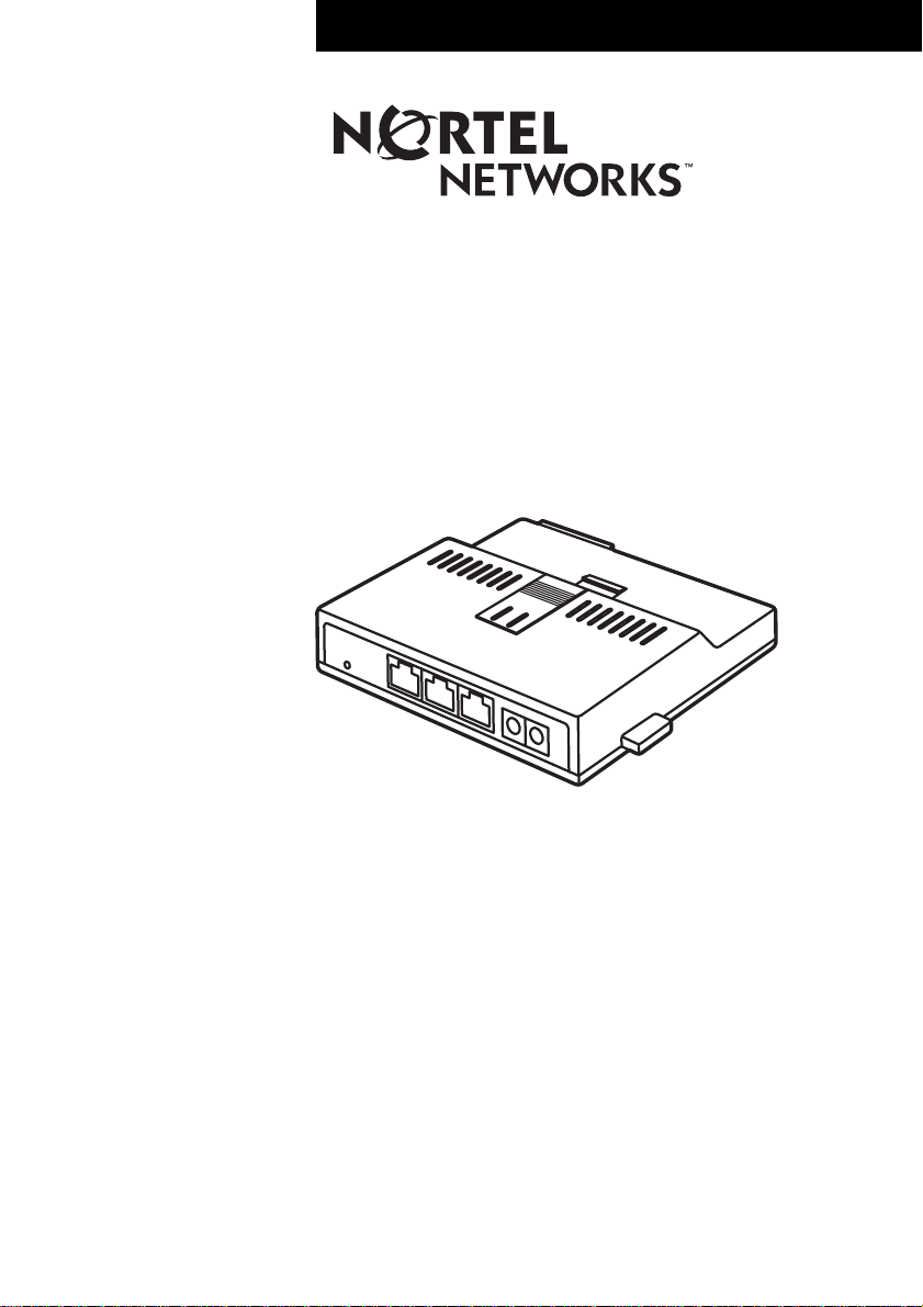
Internet Telephone Switch Module
Installation Guide
Page 2

Page 3

Introduction to the Internet Telephone Switch Module
IMPORTANT: The steps included in this guide supplement the installation
instructions included in The i2004 Internet Telephone Getting Star ted guide
that came with your telephone.
The Nortel Networks Internet Telephone Switch Module is a peripheral device
which provides added capability to the Nortel Networks i2004 Internet
Telephone. With the Internet Telephone SwitchModuleinstalledyou can run your
PC and your i2004 Internet Telephone with one Ethernet connection into your
office. This device prioritizes voice traffic at the point of interface to the
customer’sLANensuringvoicecallsalwayshaveaccesstothecustomer’sData
Network. Voice pri oritization and quality beyond the device interface i s
contingent on the quality of service the Data Network features provided between
the endpoints of the voice call.
What is in the box
Check the contents of your Internet Telephone Switch Module package to make
sure you have all of the parts listed below.
• Internet Telephone Switch Module
• Internet Telephone Switch Module Installation Guide
•Shortpowercord
• Short Ethernet cable
• AC Power adapter
• AC Power adapter cord (North America only; International order separately)
3
IMPORTANT: When usingthe Internet TelephoneSwitch Module, you MUST usethe
power adapter provided. Do not use the power adapter that came with your
i2004 Internet Telephone
. Do not plug in both power adapters.
Refer to the contents of your i2004 Internet Telephone package when assembling
the Internet Telephone Switch Module with the i2004 Internet Telephone.
Internet Telephone Switch Module Installation Guide P0919850 Issue 02
Page 4

4
Connection and installation
Caution: Severe damage to your i2004 Internet Telephone will occur if this
telephone is plugged into an ISDN connection. Consult y our System
Administratortomakesureyouarepluggingyourtelephoneintoa
10/100 BaseT Ethernet jack.
The back of the i2004 Internet
Telephone.
1. Connect one end of the short Ethernet cable to the Ethernet jack on the back of the telephone.
2. Connect one end of the short
power cord to the power jack on
the back of the telephone. Wrap
thecordaroundthepowerstrain
relief.
3. Attach the base to the telephone.
Make sure the tabs on the
See Figure i: Connecting the
components on page 6.
telephone engage fully with the
slots in the base.
4. Insert the Internet Telephone Switch Module into the slot on the base. The front of the Internet Telephone
48V 48V
Switch Module.
5. Connect the free end of the short Ethernet cable to the Ethernet jack on the front of the Module.
6. Connect the free end of the short
power cord to one of the power
48V
plugs on the front of the Module.
P0919850 Issue 02 Internet Telephone Switch Module Installation Guide
Page 5

7. Connect one end of the long
Ethernet cable, that came with your
telephone, to the LAN jack on the
Module.
5
8. Connect the free end of the long Ethernet cable to a LAN wall jack.
See Figure ii: Connecting the cords and
cables on page 6.
9. Connect one end the Ethernet
cable, that came with your PC, (not
provided) to the PC jack on the
front of the Module.
10. Connect the other end to the LAN jack on your PC.
See Figure ii: Connecting the cords and
cables on page 6.
11. Connect the AC power adapter cord to the remaining power jack on the front of the Module.
12. Connect the AC cord to the power supply module and then to an AC wall outlet.
A green LED lights on the front of the Module when the i2004 Internet Telephone
and Internet Telephone Switch Module are connected and powered. Verify data
connectivity by the state of the lamps on the Ethernet Jacks. A flashing green LED
indicates data connectivity.
Internet Telephone Switch Module Installation Guide P0919850 Issue 02
Page 6

6
Figure i: Connecting the components
Figure ii: Connecting the cords and cables
To computer
P0919850 Issue 02 Internet Telephone Switch Module Installation Guide
Page 7

Important Safety Instructions
The following safety instructions cover the installation and use of the Product. Read
carefully and retain for future reference.
Installation
CAUTION: The Internet Telephone Switch Module is intended for connection to an
unexposed plant. Connect the Internet Telephone Switch Module only to leads in the same
building structure as collocated with the host equipment. Do not connect the Internet
Telephone Switch Module to exposed plant.
For connection to Nortel Networks i2004 Internet Telephone and Nortel Internet
Telephones only.Do not connect the teledapt cabling of the Internet Telephone Switch
Module to the Public Switched Telephone Network (PSTN).
Regulations for Canada and the U.S.A.
ELECTROMAGNETIC COMPATIBILITY
Changes or modifications not expresslyapproved by the party responsible for compliance
could void the user’s authority to operate the equipment.
For Class A Host equipment
This equipment has been tested and found to comply with the limits for a Class A digital
device, pursuant to Part 15 of the FCC Rules, and ICES-003 Class A Canadian EMI
requirements. Operation is subject to the following two conditions: (1) This device may not
cause harmful interference, and (2) this device must accept any interference received,
including interference that may cause undesired operation.
7
These limits are designed to provide reasonable protection against harmful interference in
a commercial environment.
This equipment generates, uses and can radiate radio frequency energy and, if not
installed and used in accordance with the instructions, may cause harmful interference to
radio communications.
Operation of this equipment in a residential area is likely to cause harmful interference in
which case the user will be required to correct the interference at his own expense.
However, there is no guarantee that interference will not occur in a particular installation.
If this equipment does cause harmful interference to radio or television reception, which
can be determined by turning the equipment off and on, the user is encouraged to try to
correct the interference by one or more of the following measures:
• Reorient or relocate the receiving antenna.
• Increase the separation between the equipment and receiver.
Internet Telephone Switch Module Installation Guide P0919850 Issue 02
Page 8

8
• Connectthe equipment into an outlet on acircuit different from that to which thereceiver
is connected.
• Consultthedealeroranexperiencedradio/TVtechnicianforhelp.
Changes or modifications not expresslyapproved by the party responsible for compliance
could void the user’s authority to operate the equipment.
NRTL /C
Warranty Information for Canada and the U.S.A.
Do not attempt to repair this equipment. If you experience trouble, call or write for
warranty and repair information.
In the United States:
Nortel Networks
640 Massman Drive,
Nashville, TN, 37210
USA
In Canada:
Nortel Networks
30 Norelco Drive,
Weston, Ontario, M9L 2X6
Canada
For technical support, contact your authorized Nortel Networks service representative or
call 1-800-2LANWAN. Have your contract number ready.
P0919850 Issue 02 Internet Telephone Switch Module Installation Guide
Page 9

Page 10

1-800-4NORTEL
http://www.nortelnetworks.com/succession
P0919850 Issue 02
Printed in Taiwan
••••••••••••••••••••••••••••••••••••••••
 Loading...