

Page 1

Configuring IP Security Services
BayRS Version 13.10
Site Manager Software Version 7.10
Part No. 304111-A Rev 00
November 1998
Page 2

4401 Great America Pa rkw ay 8 Federal S treet
Santa Clara, CA 95054 Billerica, MA 01821
Copyright © 1998 Bay Networks, Inc.
All rights reserved. Printed in the USA. November 1998.
The information in this document is subject to change without notice. The statements, configurations, technical data,
and recommendations in this document are believed to be accurate and reliable, but are presented without express or
implied warranty. Users must take full responsibility fo r th eir a pplic a tio ns of any products specified in this document.
The information in this document is proprietary to Bay Networks, Inc.
The software described in this document is furnished under a license agreement and may only be used in accordance
with the terms of that licen se. A summary of the Software License is included in this document.
Trademarks
AN, BN, and Bay Networks are registered trademarks and Advanced Remote Node, ARN, BayRS, BayStack,
System 5000, and the Bay Networks logo are trademarks of Bay Networks, Inc.
All other trademarks and registered trademarks are t he property of their respective owners.
Restricted Rights Legend
Use, duplication, or disclosure by the United States Government is subject to restrictions as set forth in subparagraph
(c)(1)(ii) of the Rights in Technical Data and Computer So ftware clause at DFARS 252.227-7013.
Notwithstanding any other license agreement that may pertain to, or accompany the delivery of, this computer
software, the rights of the United States Government regarding its use, reproduction, and disclosure are as set forth in
the Commercial Computer Software-Restricted Rights cl ause at FAR 52.227-19.
Statement of Conditions
In the interest of improving internal design, operational function, and/or reliability, Bay Networks, Inc. reserves the
right to make changes to the pr oducts described in this document without notice.
Bay Networks, Inc. does not assume any liability that may occur du e to the use or application of the product(s) or
circuit layout(s) described herein.
Portions of the code in this software product may be Copyright © 1988, Regents of the University of California. All
rights reserved. Redistribution and use in source and binary forms of such portions are permitted, provided th at the
above copyright notice and this paragraph are duplicated in all such forms and that any documentation, advertising
materials, and other materials related to such distribution and use acknowledge that su ch portions of the software were
developed by the University of California, Berkeley. The name of the University may not be used to endorse or
promote products derived from such portions of the software without specific prior written permission.
SUCH PORTIONS OF THE SOFTWARE ARE PROVIDED “AS IS” AND WITHOUT ANY EXPRESS OR
IMPLIED WARRANTIES, INCLUDING, WITHOUT LIMITATION, THE IMPLIED WARRANTIES OF
MERCHANTABILITY AND FITNESS FOR A PARTICULAR PURPOSE.
In addition, the program and information contained herein are licensed only pursuant to a license agreement that
contains restricti ons on use and disclosure (that may incorporate by reference certai n limitations and no tices imposed
by third parties).
ii 304111-A Rev 00
Page 3

Bay Networks, Inc. Software License Agreement
NOTICE: Please carefully read this license agre ement before copying or using the accompanying software or
installing the hardware unit with pre-enabled software (each of which is referred to as “Software” in this Agreement).
BY COPYING OR USING THE SOFTWARE, YOU ACCEPT ALL OF THE TERMS AND CONDITIONS OF
THIS LICENSE AGREEMENT. THE TERMS EXPRESSED IN THIS AGREEMENT ARE THE ONLY TERMS
UNDER WHICH BAY NETWORKS WILL PERMIT YOU TO USE THE SOFTWARE. If you do not accept these
terms and conditions, return the product, unused and in the original shipping container, within 30 days of purchase to
obtain a credit for the full purchase price.
1. License Grant. Bay Networks, Inc. (“Bay Networks”) grants the end user of the Software (“Licensee”) a personal,
nonexclusive, nontransferable license: a) to use the Software either on a single computer or, if applicable, on a single
authorized device identified by host ID, for which it was originally acquired; b) to copy the Software solely for backup
purposes in support of authorized use of the Software; and c) to use and copy the associated user manual solely i n
support of authorized use of the Software by Licensee. This license applies to the Software only and does not extend
to Bay Networks Agent software or other Bay Networks software pro ducts. Bay Networks Agent software or other
Bay Networks software products are licensed for use under the terms of the applicable Bay Networks, Inc. Software
License Agreement that accomp anies such software and upon payment by the end user of the applicable license fees
for such software.
2. Restrictions on use; reservation of rights. The Software and user manuals are protected under copyright laws.
Bay Networks and/or it s licensors retain all title and ownership in both the Software and user manuals, including any
revisions made by Bay Networks or i ts licensors. The copyr ight notice must be reproduced and included with any
copy of any portion of the Software or user manuals. Licensee may not modify, translate, decompile, disassemble, use
for any competitiv e analysis, re v erse engineer , distrib ute, or create deriv ati ve works from the Softwa re or user manuals
or any copy, in whole or in part. Except as expressly provided in thi s Agreement, Licensee may not copy or transfer
the Software or user manuals, in whole or in part. The Soft ware and user manuals embody Bay Networks’ and its
licensors’ confidential and proprietary intellectual property. Licensee shall not sublicense, assign, or otherwise
disclose to any third party the Software, or any information about the operation, design, performance, or
implementation of the Software and user manuals that is confidential to Bay Networks and its licensors; however,
Licensee may grant permission to its consultants, subcontractors, a nd agents to use the Softw are at Licensee’s facility ,
provided they have agreed to use the Software only in accordance with the terms of this license.
3. Limited warranty. Bay Networks warrants each item of Software, as delivered by Bay Networks and properly
installed and operated on Bay Networks hardware or other equipment it is originally licensed for, to function
substantially as described in its accompanying user m anual during its warranty period , which begins on the date
Software is first shipped to Licensee. If an y item of S oftware f ails to so function d uring its w arranty period, as the sole
remedy Bay Networks will at its discretion provide a suitable fix, patch, or workaround for the problem that may be
included in a future Software release. Bay Network s fur ther w arra nts to Licen see that the medi a on which the
Software is provided will be free from defec ts in materials and wo rkman ship under no rmal use for a peri od of 90 da ys
from the date Software is first shipped to Licensee. Bay Networks will replace defective media at no cha rge if it is
returned to Bay Netw orks during the warran ty perio d alon g with proof of the date of shipment . This war ranty do es not
apply if the media has been dam aged as a resul t of acci dent, misuse , or ab use. The Licen see assumes all re sponsibilit y
for selection of the Software to achieve Licensee’s intended results and for the installation, use, and results obtained
from the Software. Bay Networks does not warrant a) that the functions contained in the software will meet the
Licensee’ s requireme nts, b) that the Software will operate in the hardware or software combinations tha t the L icens ee
may select, c) that the operation of the Softw a re will be uninterru pte d or error free, or d) that all defec ts in the
operation of the Software will be corrected. Bay Networks is not obligated to remedy any Software defect that cannot
be reproduced with the latest Software release. These warranties do not apply to the So ftw are if i t has been (i) altered,
except by Bay Netwo rks or in a ccordance with its instru ction s; (ii) used in con junc tion with another v en dor’s product,
resulting in the defect; or (iii) damaged by improper environment, abuse, misuse, accident, or negligence. THE
FOREGOING WARRANTIES AND LIMITATIONS ARE EXCLUSIVE REMEDIES AND ARE IN LIEU OF ALL
OTHER WARRANTIES EXPRESS OR IMPLIED, INCLUDING W ITHOUT LIMITATION ANY WARRANTY OF
MERCHANTABILITY OR FITNESS FOR A PARTICULAR PURPOSE. Licensee is responsible for the security of
304111-A Rev 00 iii
Page 4

its own data and information and for maintaining adequate procedures apart from the Software to reconstruct los t or
altered files, data, or programs.
4. Limitation of liability. IN NO EVENT WILL BAY NETWORKS OR ITS LICENSORS BE LIABLE FOR ANY
COST OF SUBSTITUTE PROCUREMENT; SPECIAL, INDIRECT, INCIDENTAL, OR CONSEQUENTIAL
DAMAGES; OR ANY DAMAGES RESULTING FROM INACCURATE OR LOST DATA OR LOSS OF USE OR
PROFITS ARISING OUT OF OR IN CONNECTION WITH THE PERFORMANCE OF THE SOFTWARE, EVEN
IF BAY NETWORKS HAS BEEN ADVISED OF THE POSSIBILITY OF SUCH DAMAGES. IN NO EVENT
SHALL THE LIABILITY OF BAY NETWORKS RELATING TO THE SOFTWARE OR THIS AGREEMENT
EXCEED THE PRICE PAID TO BAY NETWORKS FOR THE SOFTWARE LICENSE.
5. Government Licensees. This provision applies to all Software and documentation acquired directly or indirectly
by or on behalf of the United States Government. The Software and documentation are commercial products, licensed
on the open market at market prices, and were developed entirely at private expense and without the use of any U.S.
Government funds. The license to the U.S. Government is granted only with restricted rights, and use, duplication, or
disclosure by the U.S. Government is subject to the restrictions set forth in subparagraph (c)(1) of the Commercial
Computer Software––Restricte d Rig hts cla u se o f FAR 52.227-19 and the limita tio ns set o ut in this license for civilian
agencies, and subparagraph (c)(1)(ii) of the Rights in Technical Data and Computer Software clause of DFARS
252.227-7013, for agencies of t he Department of Defense or their successors, whichever is applicable.
6. Use of Software in the European Community. This provision applies to all Software acquired for use within the
European Community. If Licensee uses the Software within a country in the European Community, the Software
Directive enacted by the Council of European Commun ities Directive dated 14 May, 1991, will apply to the
examination of th e Software to facilitate interoperability. Licensee agrees to notify Ba y Networks of any such
intended examination of the Software and may procure support and assistance from Bay Networks.
7. Term and termination. This license is effective until terminated; however, all of the restrictions with respect to
Bay Networks’ copyright in the Software and user manuals will cease being effective at the date of expiration of the
Bay Networks copyright; those restrictions relating to use and disclosure of Bay Networks’ confidential information
shall continue in effect. Licensee may terminate this license at any time. The license will automatically terminate if
Licensee fails to comply with any of the terms and conditions of the license. Upon termination for any reason,
Licensee will immediately destroy or return to Bay Networks the Software, user manuals, and all copies. Bay
Networks is not liable to Licensee for damages in any form solely by reason of the termination of this license.
8. Export and Re-export. Licensee agrees not to export, directly or indirectly, t he S oft ware or re lated technical data
or information without first obtaining any required export licenses or other governmental approvals. Without limiting
the foregoing, Licensee, on behalf of itself and its subsidiaries and affiliates, agrees that it will not, without first
obtaining all export licenses and approvals required by the U.S. Government: (i) export, re-export, transfer, or divert
any such Software or technical data, or any direct product thereof, to any country to which such exports or re-exports
are restricte d or em b argoed under United States ex po r t con t rol laws and re gulations, or to any national or resident of
such restricted or embargoed countries; or (ii) provide the Software or related technical data or information to any
military end user or for any military end use, including the design, development, or production of any chemical,
nuclear, or biological weapons.
9. General. If any provision of this Agreement is held to be invalid or unenf orceable by a court of competent
jurisdiction, the remainder of the provisions of this Agreement shall remain in full force and effect. This Agreement
will be governed by the laws of the state of California.
Should you have any questions concerning this Agreement, contact Bay Networks, Inc., 4401 Great America Parkway,
P.O. Box 58185, Santa Clara, California 95054-8185.
LICENSEE ACKNOWLEDGES THAT LICENSEE HAS READ THIS AGREEMENT, UNDERSTANDS IT, AND
AGREES TO BE BOUND BY ITS TERMS AND CONDITIONS. LICENSEE FURTHER AGREES THAT THIS
AGREEMENT IS THE ENTIRE AND EXCLUSIVE AGREEMENT BETWEEN BAY NETWORKS AND
LICENSEE, WHICH SUPERSEDES ALL PRIOR ORAL AND WRITTEN AGREEMENTS AND
COMMUNICATIONS BETWEEN THE PARTIES PERTAINING TO THE SUBJECT MATTER OF THIS
AGREEMENT. NO DIFFERENT OR ADDITIONAL TERMS WILL BE ENFORCEABLE AGAINST B AY
NETWORKS UNLESS BAY NETWORKS GIVES ITS EXPRESS WRITTEN CONSENT, INCLUDING AN
EXPRESS WAIVER OF THE TERMS OF THIS AGREEMENT.
iv 304111-A Rev 00
Page 5

Contents
Preface
Before You Begin .............................................................................................................xiii
Text Conventions .............................................................................................................xiv
Acronyms ........................... .......................... .......................... ......................... ................. xv
Bay Networks Technical Publications ..............................................................................xvi
How to Get Help .............................................................................................................xvii
Chapter 1
Overview
How IPsec Works ...........................................................................................................1-1
Network Considerations .................................................................................................1-1
Supported Routers ...................................................................................................1-2
Supported WAN Protocols .......................................................................................1-2
IPsec Protection .............................................................................................................1-2
IPsec Tunnel Mode ...................................................................................................1-3
Security Protocols Overview ....................................................................................1-4
Encapsulating Security Payload ........................................................................1-4
Authentication Header .......................................................................................1-4
IPsec Services .........................................................................................................1-5
Chapter 2
Getting Started with IPsec
Security Gateway ............................................................................................................2-2
Security Policies .............................................................................................................2-3
Policy Templates ......................................................................................................2-3
IPsec Policies ...........................................................................................................2-4
Criteria Specification ..........................................................................................2-4
Action Specification ...........................................................................................2-4
Inbound Policies .......................................................................................................2-5
Outbound Policies ....................................................................................................2-5
304111-A
Rev 00
v
Page 6

Security Policy Database (SPD) ..............................................................................2-6
Security Associations .....................................................................................................2-6
Security Associations for Bidirectional Traffic ...........................................................2-7
Security Parameter Index (SPI) ................................................................................2-7
Summarizing Security Policies and SAs .........................................................................2-8
Security Protocols ...........................................................................................................2-9
IPsec Services ..............................................................................................................2-10
Confidentiality ....... ....... ...... ....... ...... ....... ...... ....... ...... ....... ...... ...... ....... ...... ....... ...... .2-10
Integrity ..................................................................................................................2-10
Authentication ........................................................................................................2-10
Installing IP Security (IPsec) Software .........................................................................2-11
Upgrading Software ...............................................................................................2-11
Installation Instructions ..........................................................................................2-11
Chapter 3
Configuring IPsec
Site Security ...................................................................................................................3-1
Configuration Security ....................................................................................................3-1
Encryption Keys .......................................................................................................3-2
Random Number Generator (RNG) .........................................................................3-2
Node Protection Key (NPK) ............................................................................................3-2
Generating and Using NPKs ....................................................................................3-3
Generating an NPK ...........................................................................................3-3
Entering the NPK on the Router ........................ ....... ...... ...... .............................3-4
Entering an NPK and a Seed for Encryption ..................................................................3-4
Changing NPKs ........................................................................................................3-5
Monitoring NPKs ......................................................................................................3-6
Enabling IPsec ................................................................................................................3-6
Creating Policies .............................................................................................................3-7
Criteria Specifications ..............................................................................................3-7
Action Specifications ................................................................................................3-7
Policy Considerations ...............................................................................................3-8
Creating Security Associations .....................................................................................3-11
Disabling IPsec .................. ...... ....... ...... ....... ...... ....................................... ...... ....... ...... .3-13
vi 304111-A Rev 00
Page 7

Appendix A
Site Manager Parameters
Node Protection Key Para meter .................................................................................... A-1
Enabling IPsec Parameters ........................................................................................... A-2
IPsec Policy Parameters ................................................................................................ A-2
Security Association Parameters ................................................................................... A-3
Appendix B
Definitions of k Commands
Appendix C
Security Policy and Security Association Examples
Inbound and Outbound Policies .....................................................................................C-1
Protect and Unprotect Security Associations (SAs) ...................................................... C-6
Index
304111-A
Rev 00
vii
Page 8

Page 9

Figures
Figure 1-1. IPsec Environment: Unique Security Associations (SAs)
Between Routers ......................................................................................1-3
Figure 2-1. IPsec Concepts: Security Gateways, Security Policies,
and Security Associations (SAs) ..............................................................2-2
Figure 2-2. IPsec Security Gateways .........................................................................2-3
Figure 2-3. Outbound and Inbound Policies ...............................................................2-6
Figure 2-4. Security Associations for Bidirectional Traffic ...........................................2-7
Figure C-1. IPsec Outbound Policies for Routers 1, 2, and 3 ....................................C-2
Figure C-2. Single Protect/Unprotect SA Pair ............................................................ C-6
Figure C-3. Multiple Protect/Unprotect SA Pairs ........................................................ C-9
304111-A Rev 00
ix
Page 10

Page 11

Tables
Table 2-1. Security Policy Specifications ..................................................................2-8
Table 2-2. Security Association (SA) Configurations ................................................2-8
304111-A Rev 0
0 xi
Page 12

Page 13

This guide describes the Bay Networks® implementation of IP Security and how
to configure it on a Bay Networks router.
Before You Begin
Before using this guide, you must complete the following procedures. For a new
router:
• Install the router (see the installation guide that came w ith your router).
• Connect the router to the network and create a pilot configuration file (see
Quick-Starting Routers or Configuring BayStack Remote Access).
Preface
Make sure that you are running the latest version of Bay Networks BayRS
Site Manager software. For information about upgrading BayRS and Site
Manager, see the upgrading guide for your version of BayRS.
304111-A Rev 00 xiii
™
and
Page 14

Configuring IP Security Services
Text Conventions
This guide uses the following text conventions:
angle brackets (< >) Indicate that you choose the text to enter based on the
description inside the brackets. Do not type the
brackets when entering the command.
Example: If the command syntax is:
ping
<
ip_address
ping 192.32.10.12
>, you enter:
bold text
Indicates command names and options and text that
you need to enter.
Example: Enter
show ip {alerts | routes
Example: Use the
dinfo
command.
}.
braces ({}) Indicate required elements in syntax descriptions
where there is more than one option. You must choose
only one of the options. D o not type the braces when
entering the command.
Example: If the command syntax is:
show ip {alerts | routes
show ip alerts or show ip routes
}
, you must enter either:
, but not both.
brackets ([ ]) Indicate optional elements in syntax descriptions. Do
not type the brackets when entering the command.
Example: If the command syntax is:
show ip interfaces [-alerts
show ip interfaces
or
]
, you can enter either:
show ip interfaces -alerts
.
italic text Indicates file and directory names, new terms, book
titles, and variables in command syntax descriptions.
Where a variable is two or more words, the words are
connected by an underscore.
Example: If the command syntax is:
show at
valid_route
<
valid_route
>
is one variable and you substitute one value
for it.
xiv 304111-A Rev 00
Page 15

Preface
screen text Indicates system output, for example, prompts and
system messages.
Acronyms
Example:
Set Bay Networks Trap Monitor Filters
separator ( > ) Shows menu paths.
Example: Protocols > I P ide nti fies the IP option on the
Protocols menu.
vertical line (
) Separates choices for command keywords and
|
arguments. Enter only one of the choices. Do not type
the vertical line when entering the command.
Example: If the command syntax is:
show ip {alerts | routes
show ip alerts
show ip routes
or
This guide uses the following acronyms:
CBC cipher block chaining
DES Data Encryption Standard
ESP Encapsulated Payload
}
, you enter either:
, but not both.
HMAC Hashing Message Authentication Code
IANA Internet Assigned Numbers Authority
ICMP Internet Con trol Message Protocol
ICV integri ty check value
IETF Internet Engineering Task Force
IP Internet P rotocol
IV initialization vector
MD5 Message Digest 5
MIB management information base
NPK node protection key
NVRAM nonvolatile random access memory
304111-A Rev 00 xv
Page 16

Configuring IP Security Services
RNG random number generator
SA security association
SAD security associations database
SPD security policy database
SPI security parameter index
VPN virtual private network
WAN wide area network
Bay Networks Technical Publications
You can now print Bay Networks technical manuals and release notes free,
directly from the Internet. Go to support.baynetwork s.com/libr ary/ tpubs/ . Fi nd the
Bay Networks product for which you need documentation. Then locate the
specific category and model or version for your hardware or software product.
Using Adobe Acrobat Re ader, you can open the manuals an d rel ease n otes, searc h
for the sections you need, and print them on most standard printers. You can
download Acrobat Reader free from the Adobe Systems Web site,
www.adobe.com.
You can purchase Bay N etworks documentation sets, CDs, and selected technical
publications through the Bay Networks Collateral Catalog. The catalog is located
on the World Wide Web at support.baynetworks.com/catalog.html and is divided
into sections arranged alphabetically:
• The “CD ROMs” section lists available CDs.
• The “Guides/Books” section lists books on technical topics.
• The “Technical Manuals” section lists available printed documentation sets.
Make a note of the part numbers and prices of the items that you want to order.
Use the “Marketing Collateral Catalog description” link to place an order and to
print the order form.
xvi 304111-A Rev 00
Page 17

How to Get Help
For product assi stance, support contracts, information abo ut educational services,
and the telephone numbers of our gl obal supp ort offices, go to the following URL:
http://www.baynetworks.com/corpor a te/co ntacts /
In the United States and Canada, you can dial 800-2LANWAN for assistance.
Preface
304111-A Rev 00 xvii
Page 18

Page 19

Chapter 1
Overview
IP Security (IPsec) is the Bay Networks implementation of the Internet
Engineering Task Force (IETF) set of standards for security services for
communications over public networks. These standards were developed to ensure
secure, private communications for the remote access, extranet, and intranet
virtual private networks (VPNs) use in enterprise communications.
The Bay Networks implementation of the IETF standard provides network
(layer 3) security services for wide area network (WAN) communications on Bay
Networks routers.
How IPsec Works
IPsec services are bundled as an Internet Protocol (IP) encryption packet. In this
way, any IPsec packet can be delivered over the In terne t like an or dinary IP pack et
to branch offices, corporate partners, or other remote organizations. Unlike an
ordinary data packet, the IPsec packet is encrypted. Data traveling across the
Internet between IPsec-configured router interfaces can be secure, encrypted,
and private.
To configure a router with IPsec, you first configure the router interface as an
IP interface. Then you add the IPsec software to the IP interface, creating a
security gateway.
Network Considerations
To install the IP Security (IPsec) software, the router must be running BayRS
Version 13.10 and Site Manager Version 7.10.
304111-A Rev 00
1-1
Page 20

Configuring IP Security Services
Supported Routers
Bay Networks IP technologies are implemented on BayRS router interfaces
supporting synchronous communications.
IPsec can pro vid e enc rypti on and a ut hentic atio n serv ice s to an y s erial int erf ace o n
the following routers:
™
•BayStack
Access Node (AN®)
• BayStack Advanced Remote Node
• Backbone Node (BN
™
• System 5000
modules
Supported WAN P rotocols
The supported WAN protocols are PPP and frame relay. Bay Networks dial
services are also supported. Dia l service s pro vide back up and demand services f or
PPP and frame relay.
™
(ARN™)
®
)
IPsec Protection
IPsec protection is implemented by making a router module interface a security
gateway. The router interface is secured with inbound and outbound security
policies that filter traffic to and from the router module. The data packets,
themselves, are protected with security associations (SAs). For information about
security gateways, see “Security Gateway” on page 2-2; for information about
inbound and outbound policies, see “IPsec Policies” on page 2-4; and for
information about security associations, see “Security Associations” on page 2-6.
Figure 1-1 sho ws ho w IPsec can prote ct data c ommunication s within a n enterpr ise
and from external hosts.
1-2
304111-A Rev 00
Page 21
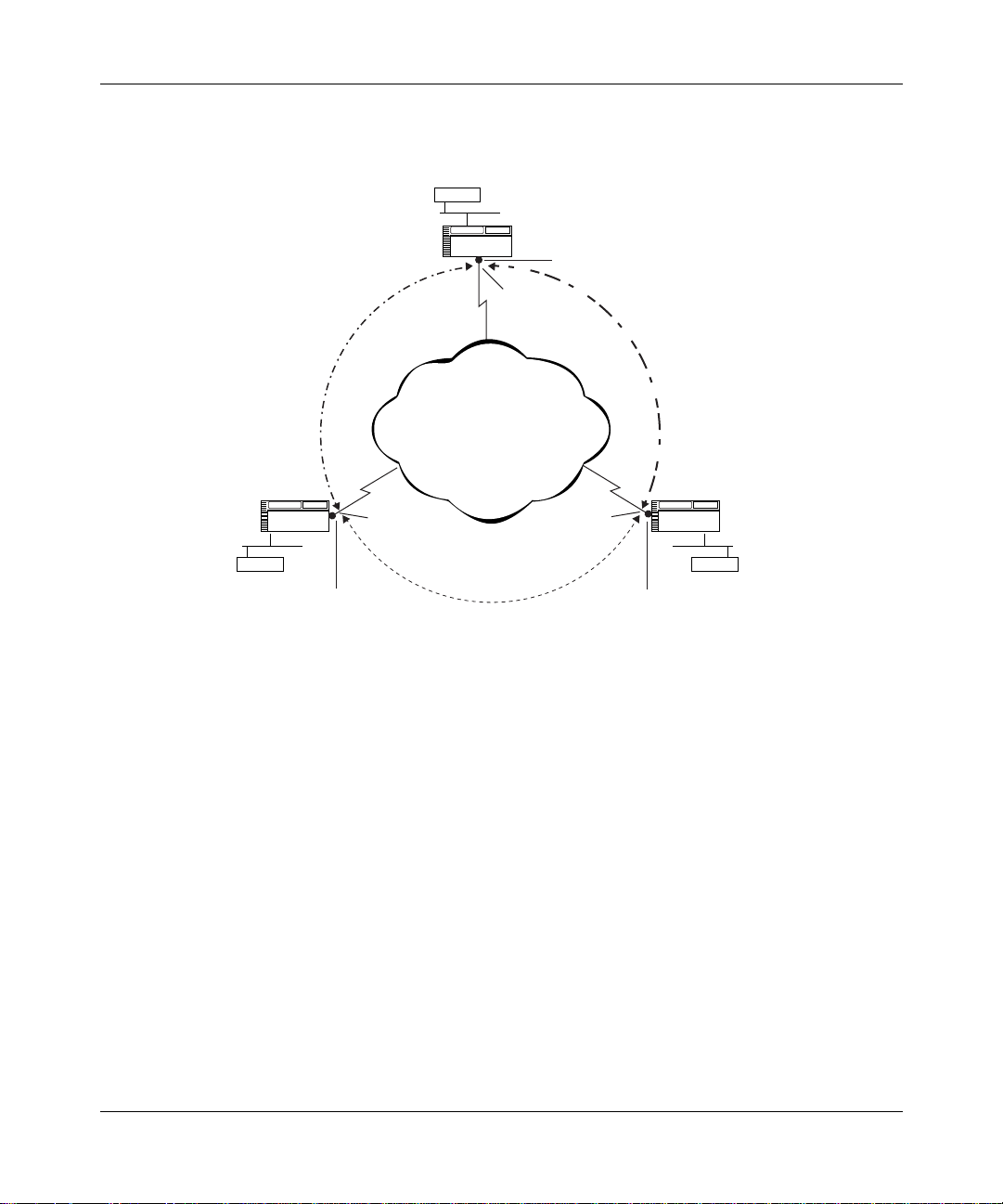
Overview
Corporate
Headquarters
Server
Router A
IP Security
Gateway
Security
Associations
(SAs A,B)
Partner
Router B Router C
Host Host
IP Security
Gateway
IPsec
Services
Public
Network
Security Associations
(SAs B,C)
IPsec
Services
Security
Associations
(SAs C,A)
Branch office
IP Security
Gateway
IPsec
Services
IP0088A
Figure 1-1. IPsec Environment: Unique Security Associations (SAs)
Between Routers
IPsec Tunnel Mode
When there is a security gateway at each end of a communication, the security
associations between the security gateways are said to be in tunnel mode. All
IPsec communications occur in tunnel mode. Tunnel mode is especially effective
for isolating and protecting enterprise traffic traveling across a public data
network as shown in Figure 1-1.
304111-A Rev 00
1-3
Page 22

Configuring IP Security Services
Security Protocols Overview
IPsec uses two protocols to provide traffic security:
• Encapsulating Security Payload (ESP)
• Authentication Header (AH)
You can use either protocol or both to protect data packets on a VPN.
Encapsulating Security Payload
The ESP protocol provides confidentiality (encryption) services. It can also
provide data integrity, data origin authentication, and an anti-replay service. One
or more of these security services must be applied whenever ESP is invoked.
ESP uses the Data Encryption Standard (DES) algorithm for encryption and
Hashing Message Authentication Code Message Digest 5 (HMAC MD5)
transform identifiers. For more information about DES, see “Security Protocols”
on page 2-9.
Authentication Header
1-4
The AH protocol provides data integrity, data origin authentication, and optional
anti-replay services.
The AH protocol uses HMAC MD5 transform identifiers.
304111-A Rev 00
Page 23

IPsec Services
IPsec services include the confidentiality, integrity , and authentication services for
data packets traveling between security gate ways.
• Confidentiality protects the privacy of communications.
• The integrity service detects modification of data packets.
• Authentication services identify the origin of every data packet.
Within the IPsec framework, additional security services are provided. An access
control service ensures authorized use of the network, and an auditing service
tracks all actions and events.
IPsec services can be configured on an interface-by-interface basis. Up to 127
inbound and 127 outbound security policies (customized) are supported on each
IPsec interface.
For more inform ation about IPsec services, see “IPsec Services” on page 2-10.
Overview
304111-A Rev 00
1-5
Page 24

Page 25

Chapter 2
Getting Started with IPsec
IPsec has three key constructs:
• Security gateways
• Security policies
• Security associatio ns (SAs)
In the IPsec context, hosts communicate across an untrusted network through
security gateways (routers configured for IPsec interfaces). Security policies
determine ho w the IPsec interfaces handle data packets for the hosts on both ends
of a connection. Security associations apply IPsec services to data packets
traveling between the security gateways.
304111-A Rev 00
Figure 2-1
associations.
shows the logical relationship between security policies and security
2-1
Page 26

Configuring IP Security Services
Security Associations
IPsec Gateway WAN Interface
Inbound Process
Unprotected SAs
Source/Dest Addr, SPI
Cipher Algo/Key,
Integrity Algo/Key
Protect SAs
Source/Dest Addr, SPI
Cipher Algo/Key,
Integrity Algo/Key
Inbound Policies
criteria & action
(bypass, drop, log)
Outbound Policies
criteria & action
(bypass, drop, log
protect)
Outbound Process
Security
Policy
Database
IP00087A
Figure 2-1. IPsec Concepts: Security Gateways, Security Policies, and Security
Associations (SAs)
Security Gateway
A Bay Networks router becomes a security gateway when you enable IPsec on a
WAN interface.
2-2
A security gateway protects one or more security associations between router
interfaces configured with IPsec software. A Bay Networks router operating as a
security gateway provides IPsec services to its internal hosts and subnetworks.
Hosts or networks on the “external” side of a security gateway are considered
“untrusted.” Host s or subnetworks on the “inter nal ” side of a security gateway are
considered “trusted” because they are controlled and securely managed by the
same network administration (Figure 2-2).
304111-A Rev 00
Page 27

Getting Started with IPsec
Trusted
network
Local
host
Outbound Policy
Security
gateway
Inbound Policy (clear text only)
IPsec interface
Untrusted
network
IPsec interface
Figure 2-2. IPsec Security Gateways
When you add IPsec services to a security gateway, its internal hosts and
subnetworks can communicate with the external hosts that directly operate IPsec
services, or with a remote security gateway that provides IPsec services for its set
of hosts and subnetworks.
Security Policies
There are two types of IPsec policies: inbound and outbound. An inbound policy
is used for data packets arriving at a security gateway, and an outbound policy is
used for data pa ck ets leaving a security gateway. Each IPsec interface can support
up to 127 inbound and 127 outbound security policies (refer to Figure 2-3
Outbound Policy
Security
gateway
Inbound Policy (clear text only)
Trusted
network
Remote
host
IP0078A
).
Policy Templates
Every IPsec polic y is ba sed on a policy template. A policy template is a pr edef ined
policy definition that you can use on any IP interface. The template specifies one
or more criteria and an action (or none) to apply to incoming or outgoing data
packets.
A policy template and every policy based on it must includ e at least one criterion,
for example, an IP source address. A policy template may include one or no
action. For example, an outbound policy might specify a protect action. The
criterion specification dete rmines wheth er a data packet matches a part icular
security policy, and the action specifies how the policy is applied to the packet.
304111-A Rev 00
2-3
Page 28

Configuring IP Security Services
IPsec Policies
When you create an IPsec policy, you control which packets a security gateway
protects.
Criteria Specification
IPsec software inspects IP packet headers based on the specified criteria to
determine whether a policy applies to a data packet.
You must include at least one of the following crit eria, and you may specify all
three criteria in an IPsec policy:
• IP source address
• IP destination address
• Protocol
To specify the protocol criterion, you must provide the numeric value assigned to
the protocol for use o v er the I ntern et. You can specify only a sin gle pr otocol value
for each polic y. The protocol number is represented in the 1-by te prot ocol field in
an IP packet header.
2-4
To obtain a list of the numeric values assigned to various protocols, see the
Internet Assigned Numbers Authority (IANA) Web site at:
http://www.iana.org
The direct path to the list of legal values tha t you can specify for an IP sec policy
protocol criterion is:
http://www.isi.edu/in-notes/iana/assignments/protocol -numbers
Action Specification
A security policy may have one action specification or none. For example, if the
IPsec interface is configured with an unprotect SA for an incoming data packet,
you do not need an action specification.
The action specifications that you can include in an inbound policy are listed in
the next section; action specifications for an outbound policy are listed in
“Outbound Policies” on page 2-5.
304111-A Rev 00
Page 29

Inbound Policies
An inbound policy determines how a security gateway processes clear-text data
packets received from an untrusted network. Every packet arriving at a security
gateway is compared with the criteria to determine whether it matches an IPsec
policy for that router. If the incoming packet matches a policy, it can enter the
router; if not, it cannot pass through the security gateway.
For an inbound security policy, the action may be:
•Drop
• Bypass
•Log
• No action
Outbound Policies
An outbound policy determines ho w a se curity gat e way proces ses data pac kets f or
transmission across an untrust ed netwo rk. You must assign an outbound poli cy fo r
all unicast traffic leaving an IPsec interface.
Getting Started with IPsec
304111-A Rev 00
For an outbound policy, the action specification may be:
•Drop
• Bypass
• Protect
•Log
Any outbound policy with a protect action specification is mapped to a protect
security association (SA). See “Security Associations” on page 2-6 for detailed
information about protect and unprotect SAs.
2-5
Page 30

Configuring IP Security Services
Trusted
network
Local
host
Outbound Policy
Security
gateway
Inbound Policy (clear text only)
IPsec interface
Untrusted
network
IPsec interface
Figure 2-3. Outbound and Inbound Policies
Security Policy Database (SPD)
The criteria (“selectors”) and action specifications used in your inbound and
outbound policies are stored in the security policy database (SPD).
IPsec defaults i n fa v or of more securit y rather th an less. I f an outbou nd or inbou nd
packet does not match the criteria of any configured outbound or inbound policy
in the SPD, the packet is dropped.
IPsec discards an y out bound clear-text data packet unle ss you explicitly configure
a policy to drop, bypass, or protect it.
Outbound Policy
Security
gateway
Inbound Policy (clear text only)
Trusted
network
Remote
host
IP0078A
Security Associations
A security association (SA) is a secure tunnel through which only the hosts that
you identify can exchange the protocol data that you specify at the degree of
protection that you specify.
A security associati on is uniqu ely iden ti f ied by an IP des tinat ion addr es s, securi ty
parameter index (SPI), and security protocol identifier (ESP in tunnel mode).
An IPsec polic y det er m ine s which packets will be handled. A secur it y association
(SA) specifies which IPsec security service (for example, confidentiality) IPsec
will apply to the packets. You can apply one or more IPsec security services.
2-6
304111-A Rev 00
Page 31

Security Associations for Bidirectional Traffic
A security association provides security services to data packets traveling in one
direction between secure gateways. To secure the traffic between two security
gateways in both directions, you must configure a protect SA for data transmitted
from the loca l IPsec interfac e and an unprotect SA for data received by the loc al
IPsec interface (Figure 2-4)
.
Getting Started with IPsec
Protect SA
Source: 132.245.145.195
Security gateway Security gateway
132.245.145.195
Destination: 132.245.145.205
Network
Unprotect SA
Source: 132.245.145.205
Destination: 132.245.145.195
Unprotect SA
Source: 132.245.145.195
Destination: 132.245.145.205
Protect SA
Source: 132.245.145.205
Destination: 132.245.145.195
Figure 2-4. Security Associations for Bidirectional Traffic
Security Parameter Index (SPI)
A security parameter index (SPI) is an arbitrary but unique 32-bit value that, when
combined with the IP destination address and the numeric value of the security
protocol used (ESP), uniquely identifies the SA for a data packet. Although the
SPI field is 32-bit, the configuration allows only 16-bit entries.
IPsec discards any incoming ESP packet if the security parameter index (SPI)
does not match any SA in the security associations database (SAD).
132.245.145.205
IP0079A
304111-A Rev 00
2-7
Page 32

Configuring IP Security Services
Summarizing Security Policies and SAs
Table 2-1 and Table 2-2 provide a frame w ork for un derstandi ng IPse c policie s and
security associations (SAs).
In Table 2-1
, each row defines the policy specifi cat i on f or the policy named in the
first column. For example, the “blue” p olicy specifies two cr iteria -- IP so urce
address and IP destination address -- and the “drop” action.
The yellow and green policies specify a protect SA act io n. You create the SAs for
a policy immediately after you specify the policy using them (Table 2-2)
Table 2-1. Security Policy Specifications
IP Source
Policy Name Protocol
Blue IP address IP address Drop
Yellow IP subnet IP subnet Protect SA
Green Range of
Black Any IP address Bypass
In Table 2-2
, the IP source and destination addresses for the SA are those of the
Address
IP addresses
tunnel through which the tr af f ic pass es. Intermedi ate router s will prote ct “protec t”
SA traffic until it reaches the IP destination address.
Table 2-2. Security Association (SA) Configurations
IP Destination
Address Action
Range of
IP addresses
Protect SA
.
Security Association SPI Cipher Integrity
Source
Address
IP address IP address 270 DES 40 Hex value HMAC MD5 Hex value
IP address IP address 260 DES 50 Hex value MD5 Hex value
2-8
Destination
Address Algorithm
Key
Length Key Algorithm Key
304111-A Rev 00
Page 33

Security Protocols
IPsec uses the following encryption services:
• Data Encryption Standard (DES)
• Message Digest 5 (MD5)
ESP uses the cipher bloc k chaining (CBC) mode of the DES encryption
algorithm. CBC is considered the most secure mode of DES. A 56-bit or 40-bit
number that you generate, known as a key, controls encryption and decryption.
Key management is manual.
DES is available in two encryption strengths:
• 56-bit DES keys (r eco mmended)
• 40-bit DES keys
Both sides of an SA must use the same encryption st rength . Normal ly, you should
use the stronger 56-bit DES key. However, if you are communicating with a
security gateway that is limited to a 40-bit DES key, you must use the 40-bit key.
Getting Started with IPsec
304111-A Rev 00
When ESP protection is used in tunnel mode, an “outer” IP header specifies the
IPsec processing destination, and an “inner” IP header specifies the (apparently)
ultimate destination for the packet. The security protocol header appears after the
outer IP header and before the inner one. Only the tunneled packet is protected,
not the outer header.
2-9
Page 34

Configuring IP Security Services
IPsec Ser vices
IPsec serv ices consist of confidentiality, integrity, and authentication.
Confidentiality
Confidentiality is accomplished by encrypting and decrypting data packets. The
Encapsulating Security Payload (ESP) protocol uses the Data Encryption
Standard (DES) algorithm in cipher block chaining (CBC) mode to encrypt and
decrypt data packets.
You set confidentiality with the cipher algorithm and cipher key parameters. The
cipher algorithm and cipher key are specified in the SAs. The algorithm and key
must be identical on both ends of an IPsec connection.
Integrity
Integrity determines whether the data has been altered during trans it. The ESP
protocol ensures that data has not been modified as it passes between the security
gateways. The ESP protocol uses the HMAC (RFC 2104) and MD5 (RFC 1321)
algorithms.
You set integrit y with the integrity algorithm a nd integrity key parameters. The
integrity algorithm and integrity key must be identical on both e nds of an IPsec
connection.
Authentication
Authentication ensures that data has been transmitted by the authorized source .
2-10
304111-A Rev 00
Page 35

Installing IP Security (IPsec) Software
Before you can enable and use IPsec services, you must create an IPsec-capable
router image. You create this image during the installation process. The
installation instructions that appear on the IP Security (IPsec) software CD are
included in this section. To install the IPsec software, you must be running BayRS
Version 13.10 and Site Manager Software Version 7.10.
Upgrading Software
If you are upgradi ng your rout er softw are , copy th e route r image fr om the upgrad e
CD to a directory on your hard drive. To modify an existing image, first use the
Router Files Manager to transfer the image to a directory on your hard drive.
For instructions on upgrading router software, see Upgrading Routers to Version
13.xx. For information about the Image Builder, the Router Files Manager, and
booting routers, see Configuring and Managing Routers with Site Manager.
Installation Instructions
Getting Started with IPsec
304111-A Rev 00
To ins tall the IP Security (IPsec) software:
1.
Insert the IP Security ( IPsec) software CD into th e CD-ROM drive.
2.
Open or create a directory for your router platform (for example, BN).
3.
Copy the files bn.exe and capi.exe to the platform directory.
4.
From Site Manager, start the Image Builder (Tools > Image Builder).
5.
Open the image in the router platform directory (for example, bn.exe).
Note that “Available Components” is empty and that “Current Components”
lists the executables.
6.
Click on Details.
Under
7.
Click on Remove.
8.
The file capi.exe is now listed under Available Components .
9.
Choose File > Save to save the image.
10.
Exit the Image Builder.
4003x Baseline Router Software, select capi.e xe.
2-11
Page 36

Configuring IP Security Services
To complete the installation process:
1.
Open the Image Builder directory:
• On a PC, the default directory is wf\builder.dir\rel<release_number>
• On a UNIX platform, the default directory is
~.builder/rel<release_number>
2.
Remove the file capi.exe from the Image Builder directory. This file is a
1-byte stub file.
3.
Copy the new capi.exe file from the router platform directory (for example,
BN) to the Image Builder directory.
4.
Restart the Image Builder and open the image from which you removed
capi.exe.
5.
Click on Details in the Available Components box.
6.
Select capi.exe and click on Add.
7.
Check the size of the capi.exe file.
If it is less than 1 KB, you have not loaded IPsec software. Repeat this
procedure or call the Bay Networks Tech nic al Solut i ons Ce nter for assistance.
2-12
8.
Save the modified image that includes IPsec to a new file and exit the Image
Builder.
9.
Copy this new image to the router and reboot.
304111-A Rev 00
Page 37

Chapter 3
Configuring IPsec
Before you configure IPsec, you need to:
• Install IP S ecurity (IPsec) software (see “Installing IP Security (IPsec)
Software” on page 2-11).
• Secure your site.
• Secure your configuration.
• Select an encryption strength.
• Use the Technician Interface secure shell to enter a node protection key
(NPK), and the n enter the same NP K in Site Manager.
Site Security
To enforce IPsec, carefully restrict unauthorized access to the routers that encrypt
data and the workstations that you use to configure IPsec. Keep in mind that the
DES and MD5 encryption standar ds that IPs ec uses are publ ic. Your data is secure
only if you properly protect the encryption keys. The configuration files that
contain these keys include safeguards to prevent unauthorized access.
Configuration Security
Store any files containing encryption keys on diskettes (or other removable
media), and keep the media in a secure place. Physically protecting your
equipment is always a good strategy and the easiest way to prevent unauthorized
access to these files.
304111-A Rev 00
3-1
Page 38

Configuring IP Security Services
Always conf i gure y our NPKs local ly, not ove r a ne tw ork. When you c onnect a PC
or a workstation to a router console port to configure encryption, use a machine
that is not connected to any other equipment.
Be sure to also protect the routers on which the NPKs reside.
Encryption Keys
IPsec uses a hierarchy of keys to protect and transmit data:
• Node protection key (NPK) -- encrypts the cipher and integrity keys
• Cipher key -- encrypts data that travels across the network in the ESP payload
• Integrity k ey -- calcul ates th e inte grity ch eck v alue (ICV), which is used at the
data packet destination to detect any unauthorized modification of the data
Caution:
compromised, all encrypted data on the router can be compromised.
The NPK is the most critical key in the hierarchy. If the NPK is
Random Number Generator (RNG)
The router software uses the secure random number generator (RNG) in Site
Manager to generate initialization vectors (IVs) that are used in the ESP DES
encryption transform ation. These values are statistically random. As its source,
the RNG uses a seed that you supply from the Technician Interface secure shell.
See “Entering an NPK and a Seed for Encryption” on page 3-4.
Node Protection Key (NPK)
The NPK encrypts cipher and in te gr ity k e ys f or MIB st orage . Not e that i t does not
encrypt, decrypt, or authenticate data.
The NPK is stored in the rou ter non v olatile r andom access memo ry (NVRAM). Its
fingerprint, which is a 128-bit version of the NPK generated by a hash algorithm,
is stored in the managem en t information base (MIB). For encrypt ion to occur, the
NPK and its fingerprint in the MIB must match.
3-2
304111-A Rev 00
Page 39

Configuring IPsec
Create and confi gure a different NPK for each secure router on you r netw or k. The
NPK should be different on every router because, if an NPK is compromised, the
security gateway for the router is compromised. If the same NPK is used for all
secure routers, the entire network could be compromised.
Caution:
Be very careful to protect all files where NPKs are stored. You
should store your NPKs o n remo vable media (for example, disk ette s) a nd k eep
the media in a secure location.
Generating and Using NPKs
You create NPKs using the Technician Interface sec ure she ll. You must then enter
the same NPKs into the Site Manager NPK parameter for that router. For details,
see the note later in this se ction.
The following steps summarize how an NPK is used. Detailed steps for using
NPKs appear later in this chapter (see “Entering an NPK and a Seed for
Encryption” on page 3-4).
1.
You are responsible for creating NPKs. The NPK value should be a random
number (16 hexadecimal digits). Use a unique NPK for each router.
2.
Enter an NPK value in the router NVRAM, using the secure shell of the
Technician Interface. Do this for each secure router.
3.
Enter the same N PK value in the Site Manager IPsec Node P rotection Key
parameter for the router that you are configuring.
Generating an NPK
304111-A Rev 00
To generate an NPK, use a met hod available at your site to create random 16-digit
hexadecimal numbers.
Note:
You can use the NPK Key Manager to generate NPKs. The NPK Key
Manager is available from the WEP Key Mana ger. To access it, open the main
window in Site Manager and choose Tools > WEP Key Manager > NPK
Manager. During IPsec processing, you can manually enter the same NPKs in
the Technician Interface. For detailed information, see Configuring Data
Encryption Services.
3-3
Page 40

Configuring IP Security Services
Entering the NPK on the Router
You enter the NPK into a router locally, using the console port and the secur e shell
section of the Technician Interface. A password protects access to the s ecure shell.
You cannot access the NPK or the password using the MIB or the routine
Technician Interface debug commands. Nor can you invoke the secure shell in a
Telnet session.
Caution:
Never use a terminal server to enter the NPK. Instead, use a laptop
computer that you can attach directly to the router. Protect the file containing
NPKs on the laptop.
Entering an NPK and a Se ed for Encryption
Before you can add IPsec t o a rout er, you must enter an NPK and create a see d fo r
encryption using the Technician Interface secure shell. IPsec uses the NPK to
encrypt and decrypt the cipher and integrity keys, and it uses the seed specified
with the
kseed
To enter an NPK and a seed for encryption:
1.
If you do not have a password for the Technician Interface secure shell, you
must creat e one. Enter
For password, enter an alphanumeric value up to 16 characters.
2.
At the Technician Interface prompt, type
Interface secure shell. (If you issue the
password, you will be prompted to do so. Use
3.
Enter the
value.
command to encrypt data.
kpassword
command. The secure shell prompts you for a random seed
kseed
<password>.
ksession
ksession
kpassword
to enter the Technician
command before setting a
and step 1.)
3-4
T y pe a random set of key stroke s. The secure sh ell infor ms you when you ha v e
entered the required number of keystrokes.
4.
Type
Type
kset npk 0x
and the 16-digit hexadecimal NPK value that you assigned to the
0x
<NPK_value>.
router that you are configuring. For more information, see “Generating and
Using NPKs” on page 3-3.
304111-A Rev 00
Page 41

The kset npk command sto re s your NPK_value in the router NVRAM, and it
calculates a hash of this value that it stores in the router MIB.
5.
Enter the save config <config_file_name> command. You cannot exit the
secure shell without saving the configuration. This is necessary so that upon
rebooting the router with the saved configuration file, the hash of the NPK in
the MIB corresponds with the NPK in NVRAM.
6.
Enter kexit to exit the secure shell.
Changing NPKs
To maintain securit y, periodically change the NPKs entered into the routers.
Configuring IPsec
To change an NPK, enter the
kset NPK command, using the steps you used to
create the original NPK (see “Entering an NPK and a Seed for Encryption” on
page 3-4).
The new NPK overwrites the original, and IPsec uses the new NPK value.
To change the NPK value used by the MIB:
1.
At the Technician Interface prompt, enter ksession.
This command allows you to enter the secure shell. Y o u are prompted for your
password.
2.
Enter your password .
The prompt changes to:
3.
Enter ktranslate
<old_NPK_value>
SSHELL.
.
The MIB now has the same NPK as the router.
4.
Save the configuration file.
304111-A Rev 00
3-5
Page 42

Configuring IP Security Services
Monitoring NPKs
If the NPK on a router does not match the NPK in the MIB, IPsec services do not
work. This type of situation usually occurs when you change a CPU board in a
router slot and the slot now lacks the current NPK, or you revert to an older
configuration that is protected by an older NPK.
View the router log to make sure that the NPK for each slot matches the NPK
value in the MIB. If not, using the secure shell, change either the router NPK
value or the MIB NPK value. For more information about changing NPKs, see
“Changing NPKs” on page 3-5.
To view the route r log events specifi c to an NPK in th e Technician Interface, enter:
log -ffwldt -eKEYMGR
Enabling IPsec
To enable IPsec, configure an IP inte rf ace usin g the Conf i gurati on Manag er. Then
add IPsec servi ces to that interface to creat e a security gateway. Use the following
steps.
3-6
Site Manager Procedure
You do this System responds
1. In the Configuration Manager window,
click on the WAN connector on which you
want to configure an IPsec interface.
2. Click on OK. The WAN Protocols window opens.
3. Choose a WAN protocol (PPP or fram e
relay).
4. Choose
5. Set the following p arameters:
• IP Address
•
Click on
Services
6. Click on OK. The IPsec Configuration for Interface
and
IP
IPSEC
Subnetwork Mask
or see
Help
.
. The IP Configuration window opens.
Configuring IP
The Add Circuit window opens.
The Select Protocols window opens.
window opens.
304111-A Rev 00
Page 43

When you use Site Manager to configure IPsec on an interface for the first time,
configure the menu items displayed in the IPsec Configuration for Interface
window in sequence, starting with the top item, Outbound Policies. You must set
an outbound policy for an IP interface before you can link a security association
(SA) to it.
Creating Policies
You create inbound and outbound policies for an IP interface by using a policy
template. A policy template is a policy definition that you create. You can use a
policy template on any IP interface.
Each template contains a co mplete policy sp ecification (criteria, range, and
action) for the interface. This means that each policy itself is completely specified
by the template. You can modify an individual policy to fit the needs of a specific
interface, as long as the values in the policy comply with the policy template
specifications. For example, an IP source address value must be in the range
specified in the policy template.
Configuring IPsec
Criteria Specifications
The criteria determine the portion of a packet header (IP source address, IP
destination address, protocol number) that is examined by IPsec. For each
criterion, you must specify a range of values. The range represents the actual
criteria values (IP addresses that are compared to the address of a packet).
Action Specifications
The action specification in a policy controls how a packet that matches the
specified criteria (and criteria range) is processed. You decide how you want
packets to be processed and apply a policy to implement your decision.
With IPsec, a packet can be processed in one of three ways:
• The packet can be dropped.
• The packet can be transmitted or received without alteration.
• The packet can be protected. In this case, a security association (SA)
is linked to th e policy.
304111-A Rev 00
3-7
Page 44

Configuring IP Security Services
The corresponding policy actions are:
•Drop
• Bypass
• Protect
• Log (a message will be written to the router log)
The first t hree acti ons are mu tually e xclu si v e. You can specify a logging act ion for
any of the other t hre e acti ons. Note t hat if an inc oming pack e t that does not mat ch
any configured policy arrives at an IPsec interface, it is dropped by default.
Policy Considerations
When you confi gure a WAN interface wit h IPsec, a ll inbound a nd outb ound traf f ic
on that interface is processed by IPsec, including traffic being forwarded.
For unicast traffic containing rout ing or cont rol information, consider configur i ng
policies that allo w such traf fi c to bypass IPsec. Fo r example, to allow ICMP traf f ic
(such as “ping” or “destination unreachable” messages) to bypass IPsec
processing, configure the first policy for th e interface with the protocol criterion
set to number 1 (ICMP) and the action specification set to bypass.
3-8
If a data packet matches the criteria for more than one policy, the first matching
policy is used.
304111-A Rev 00
Page 45

Configuring IPsec
To create an outbound policy template and policy, complete the following tasks:
Site Manager Procedure
You do this System responds
1. In the IPsec Configuration for Inte rface
window, click on
2. Click on
3. Click on
4. Enter a name in the
Click on
description on page A-3.
5. Use the
applicable range for the IP source
addresses, IP destination addresses,
and protocol criteria.
6. Use the
Policy Template
that you want applied to traffic with the
criteria that you just defined.
7. Click on OK. You return to the IPsec Policy
8. Click on
Note:
displays an inquiry window that asks whether you want to immediately create a
security association to link with this policy.
Template
Create
Help
Criteria
Action
Done
If you selected
Outbound Policies
. The IPsec Policy Template
. The Create IPsec Template window
Policy Name
, or see the parameter
menu to specify the
menu to add the action
. You return to the IPsec Outbound
Protect
from the
The IPsec Outbound Policies window
.
opens.
Management window opens.
opens.
field.
Template Management window.
Policies window.
menu for this policy, Site Manager
Action
(continued)
304111-A Rev 00
3-9
Page 46

Configuring IP Security Services
Site Manager Procedure
You do this System responds
9. Click on
10.Enter the policy name in the
Policy Name
see the parameter description on
page A-3.
11.Select a template on which to base this
policy.
Policy
12.Click on OK. You return to the IPsec Outbound
Note:
Security Associations.” If you do not want to configure an SA at this time, continue
this procedure.
13.Click on
Add Polic y
If you choose, see th e instructions for configuring an SA in “Creating
Done
. The Create Outbound Policy window
field. Click on
. You return to the IPsec Configuration
Help
or
(continued)
opens.
Policies window.
for Interface window.
3-10
304111-A Rev 00
Page 47

Creating Security Associations
Security associations enable you to provide bidirectional protection for data
packets traveling between two routers. However, each SA establishes security for
data passing in a single direction.
An SA exists for any IPsec policy supported by a security gateway. Each policy
includes security inf ormation s uch as algori thms, or k eys, that must be track ed. To
protect (encrypt or authenticate) data packets leaving the local IP interfac e, cr eat e
a protect SA and link it to an outbound policy.
To decrypt or authenticate incoming packets at the local IP interface, create an
unprotect SA. (The unpr ot ect SA d oes not need to be linked to a policy.) Then, do
the same for the IP interface on the remote router.
The cipher and integrity algorithms and keys that you specify in SAs must be
identical on both ends of a connection. You must select either the cipher or the
integrity service or both within the protect and unprotect SA parameters. For
example, the cipher key in a protect SA on the local IP interface must match the
cipher key in the u nprotect SA on the remote rou ter IP interface .
Configuring IPsec
304111-A Rev 00
Note:
SAs must be configured to encrypt, authenticate, or both. Site Manager
does not allow you to create an SA if both the Cipher Algorithm and the
Integrity Algorithm parameters are set to None.
3-11
Page 48

Configuring IP Security Services
To create a protect SA, complete the following tasks:
Site Manager Procedure
You do this System responds
1. In the IPsec Configuration for Interface
window, click on
2. Click on
3. Set the following p arameters:
• SA Source IP Address
• SA Destination IP Address
• Security Parameter Index
• Cipher Algorithm
• Cipher Key Length
• Cipher Key
• Integrity Algorithm
• Integrity Key
Click on
descriptions beginning on page A-3.
4. Click on OK. Either the Outbound Policy window or the
5. In the Outbound Policy window, select the
policy to which you want to apply an SA.
6. Click on SA. The list of SAs appears.
7. Click on the SA to apply to this policy.
8. Click on OK.
Add
Help
Protect SA
. The parameters in the Protect SA for
, or see the parameter
.
The Protect SA for Interface window
opens.
Interface window become active.
IPsec Configuration for Interface window
opens. Use the Outbound Policy window
and the following steps to link the protect
SA to an outbound policy.
3-12
304111-A Rev 00
Page 49

Disabling IPsec
To disable IPsec on all router interfaces configured for it, complete the following
tasks. (You cannot disable IPsec on an individual interface.)
You do this System responds
Configuring IPsec
Site Manager Path
1. In the Configuration Manager window,
choose
2. Choose IP. The IP menu opens.
3. Choose
4. Choose
5. Set the
Disable
6. Click on
Protocols
IP Security
Globals
IP Security Enable
.
Done
.
. The IP Security menu opens.
. The Edit IP Security Global Parameters
parameter to
. You return to the Configuration Manager
The Protocols menu opens.
window opens.
window.
304111-A Rev 00
3-13
Page 50

Page 51

Appendix A
Site Manager Pa rameters
This appendix describes the Site Manager parameters for:
• Creating a node protection key (NPK)
• Enabling IPsec
• Configuring IPsec policies
• Configuring IPsec security associations
Node Protection Key Parameter
Parameter:
Path: Configuration Manager > Protocols > IP > IP Security > Security Associations
Default:
Options:
Function:
Instructions:
MIB Object ID:
304111-A Rev 00
Node Protection Key
(SAs)
None
An 8-byte value
Used as a cryptographic key for protecting sensitive MIB objects. The NPK
value is stored in nonvolatile random access memory (NVRAM). The IPsec
software performs a hash of the NPK value, which it places in a special MIB
attribute. The NPK value stored in NVRAM is unique to the router. It is used to
encrypt the cipher and integrity keys before they are stored in the router MIB.
Enter a 16-digit hexadecimal value. (Enter the prefix 0x before the digits.)
NA
A-1
Page 52

Configuring IP Security Services
Enabling IPsec Parameters
Parameter:
Path:
Default:
Options:
Function:
Instructions:
MIB Object ID:
Parameter:
Path:
Default:
Options:
Function:
Instructions:
MIB Object ID:
IP Security Enable
Configuration Manager > Protocols > IP > IP Security > Globals
Enable
Enable
Enables or disables IPsec on a router. If this parameter is set to Disable, you
cannot implement IPse c.
To implement IP security on a router, set this parameter to Enable.
1.3.6.1.4.1.18.3.5.3.26.1.2
Maximum SPI
Configuration Manager > Protocols > IP > IP Security > Globals
384
256 through 65535
Specifies the maximum acceptable security parameter index (SPI) value for
configured security associations (SAs).
Enter a value that is unique for the security associations (SAs) defined for this
interface.
1.3.6.1.4.1.18.3.5.3.26.1.5
Disable
|
IPsec Policy Parameters
Parameter:
Path: Configuration Manager > Protocols > IP > IP Security > Outbound Policies
Default:
Options:
Function:
Instructions:
MIB Object ID:
A-2
Policy Enable
Enable
Enable
Determines whether the named policy will be used on the IP interface.
Set this parameter to Enable to activate the named policy on the IP interface.
NA
Disable
|
304111-A Rev 00
Page 53

Site Manager Parameters
Parameter:
Policy Name
Path: Configuration Manager > Protocols > IP > IP Security > Outbound Policies
Default:
Options:
Function:
Instructions:
MIB Object ID:
None
Any valid name
Specifies the name of the policy to be created using the IPsec policy template.
Enter a name to identify any policy you create using the IPsec policy template.
NA
Security Association Parameters
Parameter:
Path: Configuration Manager > Protocols > IP > IP Security > Security Associations
Default:
Options:
Function:
Instructions:
MIB Object ID:
SA IP Source Address
(SAs)
None
Any valid IP address
Specifies the IP address of the source interface for this unidirectional security
association (SA).
For a protect SA, enter the IP address of the local IPsec interface. For an
unprotect SA, enter the IP address of the remote IPsec interface.
NA
Parameter:
Path: Configuration Manager > Protocols > IP > IP Security > Security Associations
Default:
Options:
Function:
Instructions:
MIB Object ID:
304111-A Rev 00
SA IP Destination Address
(SAs)
None
Any valid IP address
Specifies the IP address of the destination interface for this unidirectional
security association (SA).
For a protect SA, enter the IP address of the remote IPsec interface. For an
unprotect SA, enter the IP address of the local IPsec interface.
NA
A-3
Page 54

Configuring IP Security Services
Parameter:
Path: Configuration Manager > Protocols > IP > IP Security > Security Associations
Default:
Options:
Function:
Instructions:
MIB Object ID:
Parameter:
Path: Configuration Manager > Protocols > IP > IP Security > Security Associations
Default:
Options:
Function:
Instructions:
MIB Object ID:
Security Parameter Index
(SAs)
256
256 through 65535
The security parameter index (SPI) is an arbitrary 32-bit value that, when
combined with the destination IP address and the numeric value of the security
protocol being used (ESP), identifies the security association (SA) for the data
packet.
Enter a value from 256 through 65535.
NA
Cipher Algorithm
(SAs)
DES CBC
None
DES CBC
|
Identifies the cipher algorithm for this security association (SA).
To implement the cipher (or confidential/encrypted) level of security, select the
Data Encryption Standard (DES) algorithm. If you select None, this level of
security will not be applied to data packets processed according to this security
association (SA); that is, the data packets will not be encrypted.
1.3.6.1.4.1.18.3.5.3.26.5.1.6
Parameter:
Path: Configuration Manager > Protocols > IP > IP Security > Security Associations
Default:
Options:
Function:
Instructions:
MIB Object ID:
A-4
Cipher Key Length
(SAs)
DES56
DES40
Identifies the cipher key length (strength) for this security association (SA).
Select a cipher key length of either 40 or 56 bits. The longer key length
(strength) provides greater security.
1.3.6.1.4.1.18.3.5.3.26.5.1.8
DES56
|
304111-A Rev 00
Page 55

Site Manager Parameters
Parameter:
Path: Configuration Manager > Protocols > IP > IP Security > Security Associations
Default:
Options:
Function:
Instructions:
MIB Object ID:
Parameter:
Path: Configuration Manager > Protocols > IP > IP Security > Security Associations
Default:
Options:
Function:
Instructions:
MIB Object ID:
Cipher Key
(SAs)
None
Any valid 8-byte value
Specifies the key for a security association cipher algorithm. This key value
must match on both sides of an SA to enable the encryption and decryption of
data packets according to the Data Encryption Standard (DES) algorithm.
Enter a 16-digit (8-byte) hexadecimal value. (Enter the prefix 0x b efore the
16 digits.)
1.3.6.1.4.1.18.3.5.3.26.5.1.7
Integrity Algorithm
(SAs)
None
None
HMAC MD5
|
Enables imple mentation of the HMAC MD5 algorithm, which dete rmines
whether a data packet was changed between the source and destination.
To implement the security integrity level, select the HMAC MD5 algorithm. If
you select None, this level of security will not be applied to data packets
processed according t o t his security association (SA); that is, I P se cur it y ca nnot
determine whether a data packet was changed between the source and
destination.
1.3.6.1.4.1.18.3.5.3.26.5.1.9
304111-A Rev 00
A-5
Page 56

Configuring IP Security Services
Parameter:
Path: Configuration Manager > Protocols > IP > IP Security > Security Associations
Default:
Options:
Function:
Instructions:
MIB Object ID:
Integrity Key
(SAs)
None
Any valid 16-byte value
Specifies the key for a security association (SA) integrity algorithm. This key
value must m atch on both sides of an SA to enable the integrity algorithm to
determine whether a data packet was changed between the source and
destination.
T o estab lish the i nte grity level of IP security, enter a 32-digit hexadecimal v a lue.
(Enter the prefix 0x before the 32 digits.)
1.3.6.1.4.1.18.3.5.3.26.5.1.10
A-6
304111-A Rev 00
Page 57

Appendix B
Definitions of k Commands
This appendix contains definitions of the “k” commands that you use to work in
the Technician Interface secure shell.
Command System Response
kexit
kpassword
kseed
ksession
kset
<subcommand>
<flags>
[
]
ktranslate
<old_NPK>
Exits the secure shell.
Changes the pass word of the secure shell.
Initializes the cryptographi c rand om number generator while in
the secure shell.
Initiates a secure shell session.
Sets parameter values in the secure shell.
Example: kset npk
key.
Also sets protected IPsec MIB objects (keys). The
command encrypts the value specified using the
NPK, and writes the encrypted value to the MIB.
Example:
kset ipsec
<value>
sets the router node protection
kset
wfIpsecEspSaEntry.wfIpsecEspSaManualCipherKey
.100.1.1.1.100.1.1.2.256 0x1234567890abcdef
Translates a configuration from an old node protection key
(NPK) value to the current NPK value.
Example: ktranslate
<old_npk>
304111-A Rev. 00
B-1
Page 58

Page 59

Security Policy and Security
This appendix provides examples of outbound and inbound policies and protect
and unprotect security associations.
Inbound and Outbound Policies
All unicast traffic must be defined by a security policy. Traffic traveling from a
security gateway is defined by an outbound policy. Traffic traveling to a secure
gateway is defined by an inbound policy. Inbound protected traffic that is
associated with an unprotect SA configured on the interface does not require a
policy.
Appendix C
Association Examples
304111-A Rev 00
As you review the security policy examples in this section, refer to Figure C-1
All of the routers have OSPF interfaces configured for type NBMA transmit
unicast frames. An outbound and an inbound bypass policy protect all unicast
traffic for the specified router subnetworks.
Security policy examples 1 and 2 show how to configure outbound policies to
protect all unicast traffic between router (RTR) 1 and router 2; examples 3 and 4
show how to configure outbound policies to protect all unicast traffic between
router 2 and router 3; and examples 5, 6, and 7 show how to configure outbound
policies to protect all traffic between router 1 and router 3. A bypass inbound
policy is i n effect for all incoming tr affic to the routers s o th at no SAs are requi red.
.
C-1
Page 60
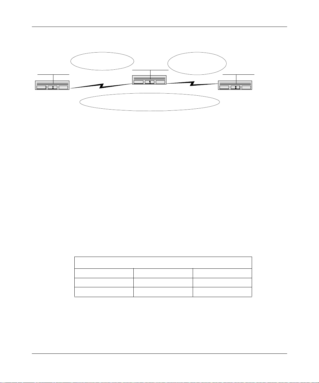
Configuring IP Security Services
192.32.5.0
12
RTR1
Protect / Unprotect SA
RTR1 to RTR2
SPI 256
IP / IPsec / OSPF(Type: NBMA)
S21
1.1.1.1
12
S21
1.1.1.2
Protect / Unprotect SA
RTR1 to RTR3
192.28.41.0
RTR2
SPI 257
Protect / Unprotect SA
RTR2 to RTR3
SPI 256
IP / IPsec / RIP
S31
2.2.2.1
Figure C-1. IPsec Outbound Policies for Routers 1, 2, and 3
Example 1: Required Policies on RTR 1 to Protect Data Between
RTR 1 Subnet 192.32.5.0 and RTR 2 Subnet 192.28.41.0
Router RTR 1 Interface S21
Policy
Action
Criteria
SA
Outbound
Protect
IP source address range: 192.32.5.0 - 192.32.5.255
IP destination address range: 192.28.41.0 - 192.28.41.255
SRC: 1.1.1.1 DST: 1.1.1.2 SPI 256
S11
2.2.2.2
192.131.141.0
12
RTR3
C-2
Security Policy
Action
Criteria
RTR1 Interface S21
Outbound Inbound
Bypass Bypass
Protocol 89 (OSPFIGP) Protocol 89 (OSPFIGP)
304111-A Rev 00
Page 61

Security Policy and Security Association Examples
Example 2: Required Policies on RTR 2 to Protect Data Between
RTR 1 Subnet 192.32.5.0 and RTR 2 Subnet 192.28.41.0
Router RTR 2 Interface S21
Policy
Action
Criteria
SA
Outbound
Protect
IP source address range: 192.28.41.0 - 192.28.41.255
IP destination addres s range: 192.32.5.0 - 192.32.5.255
SRC: 1.1.1.2 DST: 1.1.1.1 SPI 256
RTR2 Interface S21
Security Policy
Action
Criteria
Example 3: Required Policies on RTR 2 to Protect Data Between
RTR 2 Subnet 192.28.41.0 and RTR 3 Subnet 192.131. 141.0
Router RTR 2 Interface S31
Policy
Action
Criteria
SA
Outbound
Protect
IP source address range: 192.28.41.0 - 192.28.41.255
IP destination address range: 192.131.141.0 - 192.131.141.255
SRC: 2.2.2.1 DST: 2.2.2.2 SPI 256
Outbound Inbound
Bypass Bypass
Protocol 89 (OSPFIGP) Protocol 89 (OSPFIGP)
304111-A Rev 00
C-3
Page 62

Configuring IP Security Services
Example 4: Required Outbound Policies on RTR 3 to Protect Data
Between RTR 2 Subnet 192.28.41.0 and R TR 3 Subnet 192.131. 141.0
Router RTR 3 Interface S11
Policy
Action
Criteria
SA
Outbound
Protect
IP source address range: 192.131.141.0 - 192.131.141.255
IP destination address range: 192.28.41.0 - 192.28.41.255
SRC: 2.2.2.2 DST: 2.2.2.1 SPI 256
Example 5: Required Outbound Policies on RTR 1 to Protect Data
Between RTR 1 Subnet 192.32.5.0 and RTR 3 Subnet 192.131. 141.0
Router RTR 1 Interface S21
Policy
Action
Criteria
SA
Outbound
Protect
IP source address range: 192.32.5.0 - 192.32.5.255
IP destination address range: 192.131.141.0 - 192.131.141.255
SRC: 1.1.1.1 DST: 2.2.2.2 SPI 257
C-4
Security Policy
Action
Criteria
RTR2 Interface S21
Outbound Inbound
Bypass Bypass
Protocol 89 (OSPFIGP) Protocol 89 (OSPFIGP)
304111-A Rev 00
Page 63

Security Policy and Security Association Examples
Example 6: Required Policies on RTR 2 to Allow ESP Tra ff ic to Pass
Through and OSPF to Exchange Routing Updates Between
RTR 1 and RTR 2
RTR2 Interface S21
Security Policy
Action
Criteria
Security Policy
Action
Criteria
Security Policy
Action
Criteria
Outbound Inbound
Bypass Bypass
Protocol 89 (OSPFIGP) Protocol 89 (OSPFIGP)
Outbound Inbound
Bypass Bypass
Protocol 50 (ESP) Protocol 50 (ESP)
RTR2 Interface S31
Outbound Inbound
Bypass Bypass
Protocol 50 (ESP) Protocol 50 (ESP)
Example 7: Required Policies on RTR 3 to Protect Data Between
RTR 3 Subnet 192.131.141.0 and R TR 1 192.32.5.0
Router RTR 3 Interface S11
Policy
Action
Criteria
SA
304111-A Rev 00
Outbound
Protect
IP source address range: 192.131.141.0 - 192.131.141.255
IP destination addres s range: 192.32.5.0 - 192.32.5.255
SRC: 2.2.2.2 DST:1.1.1.1 SPI 257
C-5
Page 64

Configuring IP Security Services
Protect and Unprotect Security Associations (SAs)
Security as sociations (SAs) specify which IPsec servic es are applied to the data
packets traveling between the security gateways. An individual SA protects data
traveling in one direction. A protect SA is used to apply IPsec services to
outbound traffic; an unprotect SA is used to dec ryp t a nd/or authenticate incoming
data packets.
The examples in this section show how to configure both protect and unprotect
SAs.
For SA examples 1 and 2, refer to Figure C-2
Figure C-3.
RTR1
S31 - 119.68.12.1
Figure C-2. Single Protect/Unprotect SA Pair
INET
; for SA example 3, refer to
RTR2
189.132.10.1 - S52
C-6
304111-A Rev 00
Page 65

Security Policy and Security Association Examples
SA Example 1: Configuring a Single Protect/Unprotect SA Pair
In this example, a single protect/unprotect SA pair is configured using DES
encryption. Both ends of the SA pair use the same cipher algorithm, cipher key,
and integrity key (see Figure C-2
RTR 1 Protect SA RTR 2 Unprotect SA
IP source address 119.68.12.1 119.68.12.1
IP destination
address
Security parameter
index (SPI)
Cipher key length DES56 DES56
Cipher key 0x0101230405060708 0x0101230405060708
Integrity algorithm HMAC MD5 HMAC MD5
Integrity ke y 0x010123040506070890a0
189.132.10.1 189.132.10.1
256 256
b0c0d0e0f11
).
0x01012304050607 089 0a 0
b0c0d0e0f11
304111-A Rev 00
RTR 1 Unprotect SA RTR 2 Protect SA
IP source address 189.132.10.1 189.132.10.1
IP destination
address
Security parameter
index (SPI)
Cipher key length DES56 DES56
Cipher key 0x0101230405060708 0x0101230405060708
Integrity algorithm HMAC MD5 HMAC MD5
Integrity ke y 0x010123040506070890a0
119.68.12.1 119.68.12.1
256 256
0x01012304050607 089 0a 0
b0c0d0e0f11
b0c0d0e0f11
C-7
Page 66

Configuring IP Security Services
SA Example 2: Configuring Two Protect/Unprotect SA Pairs
In this example, two protect/unprotect SA pairs are configured using DES
encryption. Both ends of the SA pair use the same cipher algorithm and key. The
integrity algorithm is set to n one (refer to Figure C-2
IP source address 119.68.12.1 119.68.12.1
IP destination
address
Security parameter
index (SPI)
Cipher key length DES56 DES56
Cipher key 0x0101230405060708 0x0101230405060708
Integrity algorithm None None
Integrity ke y None None
).
RTR 1 Protect SA RTR 2 Unprotect SA
189.132.10.1 189.132.10.1
256 256
RTR 1 Unprotect SA RTR 2 Protect SA
C-8
IP source address 189.132.10.1 189.132.10.1
IP destination
address
Security parameter
index (SPI)
Cipher key length DES56 DES56
Cipher key 0x0101230405060708 0x0101230405060708
Integrity algorithm None None
Integrity ke y None None
119.68.12.1 119.68.12.1
257 257
304111-A Rev 00
Page 67

Security Policy and Security Association Examples
SA Example 3: Configuring Multiple Protect/Unprotect SA Pairs
In this example, multiple protect/unprotect SA pairs are configured between RTR
1 and RTR 2, RTR 3, and RTR 4.
• The SA pair between RTR 1 and RTR 2 uses DES56 and HMAC MD5.
• The SA pair between RTR 1 and RTR 3 uses only HMAC MD5.
• The SA pair between RTR 1 and RTR 4 uses only DES56.
As you review the tables in this example, refer to Figure C-3
189.132.10.1 - S52
RTR1
S31 - 119.68.12.1
INET
Figure C-3. Multiple Protect/Unprotect SA Pairs
129.43.12.19 - S28
192.32.1.5 - S33
.
RTR2
RTR3
RTR4
304111-A Rev 00
C-9
Page 68

Configuring IP Security Services
The following two tables show the settings for the protect/unprotect SA
pairs between RTR 1 and RTR 2 (refer to Figure C-3).
IP source address 119.68.12.1 119.68.12.1
IP destination
address
Security parameter
index (SPI)
Cipher key length DES56 DES56
Cipher key 0x0101230405060708 0x0101230405060708
Integrity algorithm HMAC MD5 HMAC MD5
Integrity ke y 0x010123040506070890a0
RTR 1 Protect SA RTR 2 Unprotect SA
189.132.10.1 189.132.10.1
257 257
0x01012304050607 089 0a 0
b0c0d0e0f11
RTR 1 Unprotect SA RTR 2 Protect SA
b0c0d0e0f11
C-10
IP source address 189.132.10.1 189.132.10.1
IP destination
address
Security parameter
index (SPI)
Cipher key length DES56 DES56
Cipher key 0x0101230405060708 0x0101230405060708
Integrity algorithm HMAC MD5 HMAC MD5
Integrity ke y 0x010123040506070890a0
119.68.12.1 119.68.12.1
256 256
0x01012304050607 089 0a 0
b0c0d0e0f11
b0c0d0e0f11
304111-A Rev 00
Page 69

Security Policy and Security Association Examples
The next two tables show the settings for the protect/unprotect SA pairs
between RTR 1 and RTR 3 (refer to Figure C-3).
RTR 1 Protect SA RTR 3 Unprotect SA
IP source address 119.68.12.1 119.68.12.1
IP destination
address
Security parameter
index (SPI)
Cipher key length DES56 DES56
Cipher key 0xFADE050403020100 0xFADE050403020100
Integrity algorithm None None
Integrity ke y None None
129.43.12.19 129.43.12.19
256 256
RTR 1 Unprotect SA RTR 3 Protect SA
IP source address 129.43.12.19 129.43.12.19
IP destination
address
Security parameter
index (SPI)
Cipher key length DES56 DES56
Cipher key 0xFADE050403020100 0xFADE050403020100
Integrity algorithm None None
Integrity ke y None None
119.68.12.1 119.68.12.1
257 257
304111-A Rev 00
C-11
Page 70

Configuring IP Security Services
The final two tables show the settings for the protect/unprotect SA pairs
between RTR 1 and RTR 4 (refer to Figure C-3).
IP source address 119.68.12.1 119.68.12.1
IP destination
address
Security parameter
index (SPI)
Cipher key length None None
Cipher key None None
Integrity algorithm HMAC MD5 HMAC MD5
Integrity ke y 0x090a0bbb0c0d0e0f11011
RTR 1 Protect SA RTR 4 Unprotect SA
192.32.1.5 192.32.1.5
256 256
0x090a0bbb0c0d0e0f11011
02030405060708
RTR 1 Unprotect SA RTR 4 Protect SA
02030405060708
C-12
IP source address 119.68.12.1 119.68.12.1
IP destination
address
Security parameter
index (SPI)
Cipher key length None None
Cipher key None None
Integrity algorithm HMAC MD5 HMAC MD5
Integrity ke y 0x090a0bbb0c0d0e0f11011
192.32.1.5 192.32.1.5
258 258
0x090a0bbb0c0d0e0f11011
02030405060708
02030405060708
304111-A Rev 00
Page 71

Numbers
Index
40-bit DES key, 2-9
56-bit DES key, 2-9
A
acronyms, xv
AH, 1-4
auditing, 1-5
authentication, 1-5
B
bidirectional traffic, 2-7
C
capi.ex e file, 2-11
cipher algorithm, A-4
cipher block chaining, 2-10
cipher key, 3-2
confidentiality, 1-5
Configuration Manager, 3-6
D
F
frame relay, 1-2
H
HMAC MD5, 1-4, 2-10, A-5
I
IANA, 2-4
IETF, 1-1
Image Builder, 2-11
installation, 2-11
integrity, 2-10
Internet Protocol, 1-1
IP destination address, 2-6
IP interface, 1-1
IP Security, 1-1, A-2
IP source address, 2-8
K
k commands, 3-4, B-1
DES, 1-4, 2-9
dial services, 1-2
E
educational services, xvii
encryption, 2- 9, 3-1
ESP, 1-4, 2-7
304111-A Rev 00
L
log, 3-6, 3-8
M
MD5, A-5
MIB, 3-2, 3-5
Index-1
Page 72

N
NPK, 3-2, A-1
NVRAM, 3-5, A-1
subnetwork, 2-2
support, Bay Netw o rks , xvii
T
P
password, 3-4
policy template, 2-3, 3-7, 3-9
PPP, 1-2
product support, xvii
protocol, 1-2, 2-4
public data network, 1-3
publications, Bay Networks, xvi
R
random number, generating, 3-3
RNG, 3-2
router, 1-2
routers, supported, 1-2
S
SAD, 2-7
secure shell, 3-4
security association, 3-11
protect, 2-4, 2-5, 3-12
Site Manager parameters, A-3
unprotect, 2- 4, 3-11
security gateway, 2-3, 2-9
security parameter index (SPI), 2-6, 2-7, A-2
security policy
action, 2-4, 2-5, 3-7, C-1
criteria, 2-3, 2-4, 3-7
examples, C-1
inbound, 1-5, 2-3, 2-5
outbound, 1-5, 2-3, 2-5, 3-9, A-2
Site Manager parameters, A-2
security policy database (SPD), 2-6
seed for encryption, generating, 3-4
Site Manager, 1-1, 3-6, A-1
technical publications, xvi
technical support, xvii
Technician Interface, 3-3, 3-4
text conventions, xiv
tunnel mode, 1-3
V
VPN, 1-1
W
WAN, 1-2, 2-2, 3-8
WEP Key Manager, 3-3
Index-2
304111-A Rev 00
 Loading...