

Avaya Integral E3 User Manual

Wandmontage Telefon Integral E3
Wall mounted telephone – Integral E3
Montaje mural teléfono Integral E3
Montage mural du téléphone Integral E3
Montaggio a parete del telefono Integral E3
Wandmontage telefoon Integral E3
IP Telephony
Contact Centers
Mobility
Services
Deutsch
Wandmontage Telefon Integral E3
Gehen Sie in der angegebenen Reihenfolge vor, um Ihr Telefon Integral E3 an
der Wand zu montieren. (Die Ziffern im Text verweisen auf die Abbildungen
auf der nächsten Seite).
Achtung: Elektronische Bauteile können zerstört werden!
Berühren Sie keine elektronischen Bauteile! Beachten Sie die
Handhabungsregeln zur Arbeit mit Elektrostatisch Gefährdeten
Bauelementen (EGB).
1. Entfernen Sie alle Anschlusskabel vom Telefon (inkl. Hörerschnur).
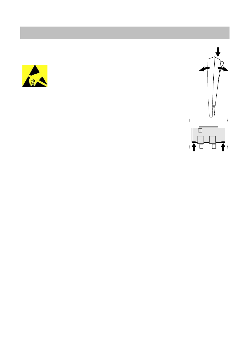
2. Deckel und Bodenteil trennen: Nehmen Sie das Telefon in die Hand, die
hintere höhere Seite nach oben gerichtet (Abbildung rechts). Drücken Sie
mit einem Daumen kräftig mittig auf die Oberseite des Bodenteils (a).
Ziehen Sie gleichzeitig Bodenteil und Deckel auseinander (b).
3. Anschlussbuchsendeckel entfernen: Drücken Sie mit beiden Daumen gleichzeitig innen gegen die Rasten (4) für den Anschlussbuchsendeckel (5), entrasten ihn dadurch und drücken ihn nach
außen heraus (Abbildung rechts).
4. Drehen Sie das Bodenteil um 180° (höhere Seite unten). Positionieren Sie es an der Wand. Zeichnen Sie die Bohrlöcher durch die
Löcher im Bodenteil (1, 7) an.
5. Bohren Sie die Löcher für die gewünschten Schrauben und Dübel (z. B. Dübel
∅ 6 mm und Schrauben Typ Spanplattenschraube, Halbrundkopf, Kreuzschlitz
(2.692.165.127) SR 4,0 x 45 mm).
6. Führen Sie die lange Seite der Höreranschlussschnur in den rechten Kabelkanal (2)
des Bodenteils ein.
7. Entfernen Sie die Außenisolierung der Telefonanschlusskabels (mind. 10 cm). Legen
Sie diese in einen Kabelkanal (3) ein, so dass ein mindestens 10 cm langes
Ende übersteht.
8. Nutzen Sie das Langloch (7), um die senkrechte Ausrichtung des Bodenteils zu korri-
gieren und schrauben es fest.
9. Schrauben Sie die Befestigungsschraube (9) der Hörerstütze (10) vom Deckel ab.
Ziehen Sie die Hörerstütze aus dem Deckel.
10. Setzen Sie die Hörerstütze gedreht wieder in den Deckel: Der Haken für den Hörer
(13) muss in die Hörerstützenöffnung a (12) gesteckt werden und die Parkhalterung
(14) in die Hörerstützenöffnung b (11).
11. Schrauben Sie die Hörerstütze fest.
12. Ziehen Sie die Schraubklemme (17) von der Steckerleiste ab.
13. Schließen Sie die beiden Adern des Telefonanschlusskabels an die Schraubklemme
an.
Achten Sie stets darauf, dass das Telefonanschlusskabel nicht stark geknickt
wird oder auf Bauteile drückt.
14. Stecken Sie die Schraubklemme wieder auf die Steckerleiste (Position ist eindeutig)
15. Legen Sie den Deckel mit der unteren Raste (18) unten an das Bodenteil an.
16. Stecken Sie die Hörerschnur in die Buchse Hörerschnur (15) ein.
17. Drücken Sie den Deckel oben gegen das Bodenteil, bis die obere Raste (8) fasst.
a
bb
4.999.071.832 S 0802 S de S gb S es S fr S it S nl
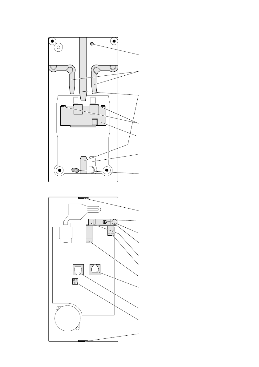
Bodenteil (Innenansicht)
1 Loch für
Befestigungsschraube
2 Kabelkanal für
Höreranschlussschnur
(Außenseite)
3 Kabelkanal für
Telefonanschlusskabel
(Außenseite)
4 Rasten für Anschluss-
buchsendeckel
5 Anschlussbuchsendeckel
6 Kabelkanal für
Telefonanschlussschnur
(Außenseite)
7 Langloch für
Befestigungsschraube
Deckel (Innenansicht)
8 Obere Raste
9 Befestigungsschraube
der Hörerstütze
10 Hörerstütze
11 Hörerstützenöffnung b
(unter der Hörerstütze)
12 Hörerstützenöffnung a
(unter der Hörerstütze)
13 Haken für Hörer
14 Parkhalterung
15 Buchse Hörerschnur
16 Buchse Telefonkabel
17 Schraubklemme
18 Untere Raste
English
Wall mounted telephone – Integral E3
Follow the directions below on how to mount your Integral E3 telephone on
the wall. (The numbers in the text refer to the illustrations on the next page).
Caution: Electronic components can be destroyed.
Do not touch any electronic components. Pay attention to the
handling when working with electrostatically endangered
components.
1. Remove all cables from the telephone (incl. handset cable).
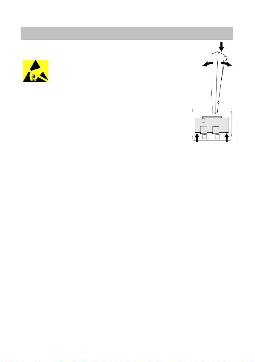
2. Separate the cover from the main body: Pick the telephone up with the
rear, raised side pointed upwards (illustration right). Using your thumb,
press firmly in the middle of the upper part of the main body (a).
At the same time, pull the cover and the main body apart (b).
3. Remove the socket cover: Press both thumbs simultaneously
against the inner indentations (4) on the socket cover (5), unlatch it
and press it outwards (illustration right).
4. Turn the main body 180° (raised side below). Position it on the wall.
Mark the drill holes through the holes of the main body (1, 7).
5. Drill the holes for the desired screws and wall plugs (e. g. wall plug ∅ 6 mm
and screw type – particle board, half round, recessed head (2.692.165.127)
SR 4.0 x 45 mm).
6. Guide the long side of the handset cable into the right cable canal (2) on the main
body.
7. Remove the outer insulation from the telephone cable (at least 10 cm). Place it in a
cable canal (3), in such a way that there is at least a 10 cm-long end.
8. Use the long hole (7) to correct the vertical position of the main body and fasten it
firmly.
9. Unscrew the fixing screw (9) of the handset cradle (10) from the cover. Remove the
handset cradle from the cover.
10. Place the handset cradle in the opposite direction back into the cover: The hook for
the handset (13) must be fixed into the handset cradle opening a (12) and the holder
(14) must be fixed into the handset cradle opening b (11).
11. Screw the handset cradle firmly.
12. Remove the terminal screw (17) from the multipoint connector.
13. Connect both of the wires of the telephone cable to the terminals screw.
Be sure that the telephone cable is never kinked or pressed on components.
14. Replace the terminals screws back onto the multipoint connector (position is unique)
15. Place the cover with the lower indentation (18) underneath the main body.
16. Put the handset cable into the handset socket (15).
17. Press the cover upwards against the main body until the upper indentation (8)
latches.
a
bb
4.999.071.832 S 0802 S de S gb S es S fr S it S nl
 Loading...