

Avaya INDeX Media Gateway Installation Manual

INDeX Media Gateway
Installation Manual
38DHB0002UKGA Issue 1 (12/05/2004)

Page 2 - Contents
Contents
INTRODUCTION .....................................................................................................................................................3
GENERAL ...............................................................................................................................................................3
SCOPE OF THIS MANUAL .........................................................................................................................................3
THE INDEX MEDIA GATEWAY .............................................................................................................................4
INDEX MEDIA GATEWAY MODULE ..........................................................................................................................5
PREPARING FOR INSTALLATION .......................................................................................................................6
INTRODUCTION .......................................................................................................................................................6
TOOLS & PARTS REQUIRED ....................................................................................................................................6
SPACE REQUIREMENTS...........................................................................................................................................7
ENVIRONMENTAL REQUIREMENTS ............................................................................................................................8
POWER SUPPLY REQUIREMENTS.............................................................................................................................9
CABLING & TRUNKING REQUIREMENTS ..................................................................................................................10
INDEX PROGRAMMING CONNECTIONS ..................................................................................................................11
IP OFFICE PROGRAMMING CONNECTIONS .............................................................................................................11
INSTALLING THE IP OFFICE ADMINISTRATION SUITE................................................................................................12
CONVERTING THE INDEX DATABASE.....................................................................................................................13
INSTALLING A NEW SYSTEM ............................................................................................................................15
UNPACKING..........................................................................................................................................................15
INDEX CONFIGURATION .......................................................................................................................................17
IP OFFICE SYSTEM PROGRAMMING ................................................................................................................26
INTRODUCTION .....................................................................................................................................................26
SYSTEM HANDOVER ..........................................................................................................................................27
CHECKLIST...........................................................................................................................................................27
REFERENCE SECTION........................................................................................................................................28
EMC & EARTHING REQUIREMENTS .......................................................................................................................28
GROUNDING .........................................................................................................................................................29
OUT OF BUILDING TELEPHONE INSTALLATIONS.......................................................................................................30
IP406 OFFICE PLATFORM.....................................................................................................................................32
IP412 OFFICE PLATFORM.....................................................................................................................................35
EXPANSION MODULES ..........................................................................................................................................38
IP OFFICE COUNTRY VARIANTS.............................................................................................................................43
SAFETY AND HOMOLOGATION STATEMENTS ...........................................................................................................46
TECHNICAL DATA..................................................................................................................................................49
REGULATORY INSTRUCTIONS FOR USE ..................................................................................................................69
INDEX ....................................................................................................................................................................70
Page 2 - Contents INDeX Media Gateway Installation Manual
General 38DHB0002UKGA Issue 1 (12/05/2004)

Page 3 - General Introduction
Introduction
General
This manual covers the installation of an INDeX Media Gateway operating with IP
Office Level 2.1+ or higher software. It is intended for use by installers and
maintainers who have successfully completed the appropriate IP Office training
courses.
Ensure that you have read and understood this manual before beginning
installation.
Scope of this Manual
This manual covers the following subjects and should be read in the sequence
shown below:
– INDeX Media Gateway:
This section provides details of the INDeX Media Gateway module and how it
allows existing INDeX equipment to be connected to either Avaya IP406 or
IP412 Office platforms. An illustration of a fully configured INDeX Media
Gateway is provided.
– Preparing for a new system:
These sections provide all the information required and the actions to be
performed to physically install an INDeX Media Gateway, i.e. what tools are
required, the environmental/power requirements, etc. It also covers extracting
the existing INDeX database so that the information can be imported into the IP
Office platform.
– Installing a new system:
This section details the recommended sequence for installing the INDeX media
Gateway into an existing INDeX system. This manual only covers the
installation of the IP Office suite of programs. For full details refer to the IP
Office Installation Wizard Help files and/or to the Manuals contained on the
documentation CD (supplied with IP406 or IP412 units).
– Reference Section:
This provides all the necessary Safety, Homologation Statements and
Regulatory Instructions for Use required. This section also detail where further
information, including other Manuals and support telephone numbers, can be
obtained. It also includes technical data on the Port Pinouts/Safety
classifications, cables, and basic technical specifications only. Descriptions of
the functionality, features and performance of the IP Office are covered by the
Product Description.
Page 3 - Introduction INDeX Media Gateway Installation Manual
General 38DHB0002UKGA Issue 1 (12/05/2004)

Page 4 - Scope of this Manual The
The INDeX Media Gateway
The INDeX Media Gateway provides the means of connecting existing INDeX 8
slot cabinets, along with their associated digital telephones, to either IP406 or
IP412 Office platforms. Up to 180 digital telephones can be supported on an IP406
and up to 360 digital telephones on an IP412 Office Platform. This is achieved by
using an IP Office 412 with the maximum of 12 Digital Subscriber Line Cassettes
(DSLCs) in the INDeX cabinets.
Notes: 1. Although a DSLC cassette can support up to 32 channels, when used
with Media Gateway only the first 30 channels per DSLC are used.
2. As both the INDeX Media Gateway and the IP Office Expansion
Modules (see page 38) share the same Expansion ports on the rear of
the IP Office then, for each IP Expansion Module used, one less DSLC
can be used.
The major elements of an INDeX Media Gateway, using the maximum of 12
DSLCs, is shown below:
Page 4 - The INDeX Media Gateway Installation Manual
38DHB0002UKGA Issue 1 (12/05/2004) INDeX Media Gateway
Contents - Page 5
INDeX Media Gateway Module
General
The INDeX Media Gateway provides the means of connecting existing INDeX
cabinets, along with their associated digital telephones, to either IP406 Office
(maximum 180 digital telephones) or IP412 Office (maximum 360 digital
telephones) platforms. Details on either Office platform, the expansion modules or
IP Office country variants can be found in the Reference Section on page 28.
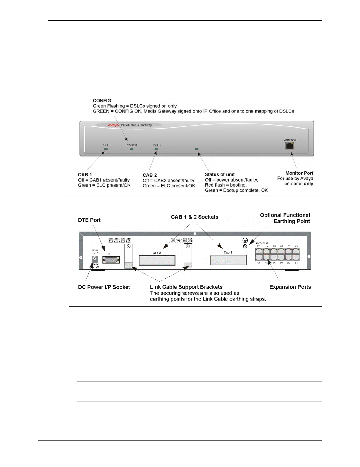
Media Gateway - Front View
Media Gateway - Rear View
Port connections
• DC Power I/P Socket: Only use the external 24V DC power supply supplied
with the Media Gateway kit (including 3-pin earthed plug).
• DTE Port: A 9-way D-type socket. Used for maintenance only.
• CAB1/CAB2 Sockets: 96-Way sockets for the Link Cables to the ELCs in the
INDeX cabinets 1 & 2 respectively. The CAB2 socket is normally blanked off
with a protection plate. Hence, where a 2nd INDeX cabinet is to be connected,
remove this plate from over the CAB2 socket.
• Expansion Ports 1-12: Used to connect to the IP412 or IP406 Office Platforms.
Port Pinouts and Cables
• For Port Pinouts and Cables, refer to pages 49 and 53 respectively.
Functional Earth
For Functional Earth connections see page 29.
Installation Manual INDeX Media Gateway Contents - Page 5
38DHB0002UKGA Issue 1 (12/05/2004)

Page 6 - Introduction Pre
Preparing for Installation
Introduction
This section reviews the requirements for installing an INDeX Media Gateway. You
must meet these requirements for the system to operate safely and in the intended
manner.
This section covers
:
– Tools & Parts Required on page 6.
– Space Requirements on page 7.
– Environmental requirements on page 8.
– Power Supply Requirements on page 9.
– Cabling & Trunking Requirements on page 10.
EMC & Earthing Requirements are detailed on page 28.
Tools & Parts Required
General:
– Pozidrive No. 1 screwdriver for removal of IP Office unit covers.
– Pozidrive No. 4 screwdriver for IP Office Analog Trunk 16 expansion module
grounding post.
– 6.5mm Slothead screwdriver for removal of INDeX cabinet covers.
– No.1 Crosspoint for INDeX cassette screws and cabinet grille plate.
– Cutter/knife for cable ties.
– Cable ties - 3mm x 50mm.
Note: In addition, ensure that you have sufficient cables that are not supplied
with the modules:-
- Line Cords for structured cabling (see page 53)
- Power supply cables (see page 44).
- Link Cable(s). 2.9mtrs (38YCN00001SEC) or 1.7mtrs
(38YCN00001SEK). The earth braids (two off) for connection to the
INDeX Media Gateway are supplied with the module.
IP Office Programming
:
These are the tools required for programming of a newly installed IP Office
system.
– PC running Windows 98/2000/ME/XP or NT with the following specification:
Intel Pentium ll 333Mhz or faster, 100MB HD space, CD-ROM drive, COM
port, terminal emulation (e.g. HyperTerminal) and a super VGA Monitor (set to
1024x768).
– PC with a LAN card with either a fixed IP address (allocated by your system
administrator) or be using DHCP to obtain an IP address.
– IP Cat. 5E patch cable (red – supplied with system see page 55).
– IP Office Administration CD (supplied with system).
– IP Office Manager Application Manual (supplied on CD with system).
– IP Office Feature Key (where software that requires a Licence Key is to be
installed).
Page 6 - Preparing for Installation Installation Manual
38DHB0002UKGA Issue 1 (12/05/2004) INDeX Media Gateway

Contents - Page 7
Space Requirements
For INDeX:
The INDeX Cabinets should have already been installed. However, check the
following guide line:
WARNING:
Cabinets must not be mounted vertically above each other except in a
proper fan cooled rack installation (see Rack Installation Notes Manual).
– Allow a minimum clearance of 50mm to the left and right of the cabinet.
– Between cabinets, allow a separation of 50 to 100mm.
– Allow for trunking to the lower-right corner of each cabinet.
– Check there is suitable lighting for installation, system programming and future
maintenance. Similarly check that there is sufficient working space for
installation and future maintenance.
– Check that there is sufficient space for any anticipated future expansion or
addition of peripheral equipment, e.g. Voice and CCC systems and other
Server PC products.
– Ensure that likely activities near the system will not cause any problems, e.g.
access to and maintenance of any other equipment in the area.
For IP Office:
Check that the planned location meets the following requirements.
Height: IP406, IP412 and all Expansion modules are 71mm(2.8 inches) high.
Hence the total height of a system is the number of modules multiplied by
71mm (2.8 inches).
Width: IP406, IP412 and all Expansion modules are 445mm (17.5 inches) wide.
Depth: IP40, 412 and all Expansion modules are 245mm (9.7 inches) deep.
• IP403, IP406, IP412 and Expansion modules can be mounted in 19"
racks (see page 25).
• When modules are free standing (ideally mounted one upon another),
allow a minimum clearance of 50mm (20 inches) either side for cable
trunking.
• Check there is suitable lighting for installation, system programming
and future maintenance.
• Check that there is sufficient working space for installation and future
maintenance.
Ensure that likely activities near the system will not cause any problems, e.g.
access to and maintenance of any other equipment
Installation Manual INDeX Media Gateway Contents - Page 7
38DHB0002UKGA Issue 1 (12/05/2004)

Page 8 - Environmental requirements Pre
Environmental requirements
The planned location must meet the following requirements:
– Check that the area is a well ventilated, having a temperature range of 0°C to
+40°C and a humidity range of 10% to 90% non-condensing.
– Check there are no flammable materials in the area.
– Check there is no possibility of flooding.
– Check that no other machinery or equipment needs to be moved first.
– Check that it is not an excessively dusty atmosphere.
– Check that the area is unlikely to suffer rapid changes in temperature and
humidity.
– Check for the proximity of strong magnetic fields, sources of radio frequency
and other electrical interference.
– Check there are no corrosive chemicals or gasses.
– Check there is no excessive vibration or potential of excessive vibration,
especially of the cabinet mounting surface.
IMPORTANT SAFETY INSTRUCTIONS
When using your telephone equipment, basic safety precautions should always be
followed to reduce the risk of fire, electric shock and injury to persons, including
the following:
1. Do not use this product near water, for example, near a bath tub, wash bowl,
kitchen sink or laundry tub, in a wet basement or near a swimming pool.
2. Avoid using a telephone (other than a cordless type) during an electrical storm.
There may be a remote risk of electric shock from lightning.
3. Do not use the telephone to report a gas leak in the vicinity of the leak.
4. Use only the power cord and batteries indicated in this manual. Do not dispose
of batteries in a fire. They may explode. Check with local codes for possible
special disposal instructions.
SAVE THESE INSTRUCTIONS.
Page 8 - Preparing for Installation Installation Manual
38DHB0002UKGA Issue 1 (12/05/2004) INDeX Media Gateway

Contents - Page 9
Power Supply Requirements
INDeX, INDeX Media Gateway, IP Office and Expansion Modules should only be
connected to a clean power supply or a UPS. Check the following:
INDeX Cabinets:
– Each cabinet requires a separate switched
mains supply. This should be a
230V (±10%), 50Hz single-phase mains supply rated at 10A maximum. The
supplied mains-in cable length is 3 metres. Each mains supply must provide
an earth connection (see "EMC & Earthing Requirements" on page 28).
– The INDeX power supply must be a PSU8.
INDeX Media Gateway, IP Office and Expansion Modules:
– IP Office modules require a separate switched mains supply. Power on the
Expansion Modules first. If the main IP Office Module does not detect an item
at power on, it will never use it. If power is switched on from a central point for
all modules, then, as the main unit is the slowest to start, this will be taken
care of automatically.
– Standard Lump-in-Line Power Supply units are supplied with each must be
used.
CAUTION: The Lump-in-Line PSUs supplied with each IP Office module must
only be connected to a 50/60Hz, 100-240V power source.
UPS Equipment:
– The use of UPS's to support the INDeX Media Gateway during mains power
failure is highly recommended. Such equipment also provides mains
conditioning. Contact Avaya for details of preferred and tested suppliers and
models. Contact Avaya for details of preferred and tested suppliers and
models.
Installation Manual INDeX Media Gateway Contents - Page 9
38DHB0002UKGA Issue 1 (12/05/2004)

Page 10 - Cabling & Trunking Requirements Pre
Cabling & Trunking Requirements
The table below shows the maximum cable distances allowed from INDeX DSLC
cassettes to the MDF and to the INDeX Media Gateway module. If the cabling is
already in place, check that it does not exceed those distances.
Check also that the correct types of cables and sockets have been used and that
the site wiring is clearly labelled. All cables and wires should run through protective
trunking or ducts wherever possible.
Table of Cable Distances
.
Cabinet to :
Cable Type
Standard
Cable
Length
Maximum
Length
To MDF 32 twisted-pair cable 3m 15m
MDF to:
20 Series Terminal Socket Type CW1308 (1 twisted pair) – 1000m
Two-Wire Socket Type CW1308 (1 twisted pair) – 2400m
Mains – 3m 3m
INDeX to:
Media Gateway Module Link Cable 1.7 or 2.9mtrs
INDeX Media Gateway to:
IP Office Module Expansion Cable 1.0mtrs
Note: It is recommended that the distance between the INDeX cabinet(s) and the
INDEX Media Gateway modules is restricted to less than 2mts maximum.
Similarly, that the maximum distance between the IP Office module and the
INDeX Media Gateway is restricted to less than 1mtr.
IDC Cable Connection Requirements
The DSLC cassettes used in the INDeX connect to the MDF using an INDeX 32pair cable. We strongly recommended that you provide IDC connection points for
every cable pair even if the cassette does not require all 32 pairs. This allows for
system expansion and maintenance with the minimum cable rewiring.
The INDeX 32-pair cable uses wires with a conductor diameter of 0.4mm (26
AWG).
– In excess of 100 re-terminations of the same wire diameter is possible
provided that an approved IDC tool is always used.
– When new
IDC connectors are used it is possible to terminate two wires of the
same diameter in one contact, i.e. 2 x 0.4mm diameter wires.
– It is not acceptable to terminate two wires of different diameters in one contact.
Once an INDeX 32-pair cable wire has been terminated (wires of 0.4mm
diameter), a wire of greater diameter (e.g. 0.5mm) must not be terminated on
top of it, even if only for test purposes. Such an action could result in poor
contact of the smaller wire.
– Once a IDC connector has been terminated with a wire of diameter greater
than 0.4mm it cannot be used for an INDeX 32-pair cable wire connection as
this will result in poor contact.
– It is bad practice to use old IDC connectors unless you are certain that only
0.4mm diameter wires have previously been used in them.
Page 10 - Preparing for Installation Installation Manual
38DHB0002UKGA Issue 1 (12/05/2004) INDeX Media Gateway

Contents - Page 11
INDeX Programming Connections
The INDeX supports programming connections through either serial ports or a
10/100 Base-T ethernet port connection.
Serial Connections
The INDeX supports programming via serial cable connections. This can be either
a direct serial cable connection or a modem serial connection.
Ethernet Port Connections
The INDeX has a 10/100 Base-T ethernet port. This can be used to connect the
INDeX to a LAN or directly to a PC network card for programming access.
IP Office Programming Connections
The IP Office supports programming through any one of it's 10/100 Base-T hub
port connections. The tools required for programming of a newly installed IP Office
system are:
– PC running Windows 98, NT, 2000, XP or ME (see page 6).
– PC with a LAN (NIC) card with either a fixed IP address (allocated by your
system administrator) or by using DHCP to obtain an IP address.
– IP Office Cat. 5E patch cable (red – supplied with system see page 55).
– IP Office Administration CD (supplied with system).
– IP Office Manager Application Manual (supplied on CD with system).
– IP Office Feature Key (where software that requires a Licence Key is to be
installed).
Note: Once installed, the software level of all software fitted to the IP Office
system can be identified. With Manager running, use
File/Advanced/Upgrade to display menu. Refer to the Manager Application
Manual for details of system configuration, software upgrade, etc.
PC to IP Office LAN Port Connection
An IP Office system, when first powered up, will scan the LAN for a DHCP server
that will allocate it with an IP address. If the IP Office system does not find a
DHCP server then it will automatically become a DHCP server itself with an IP
address of 192.168.42.1. The IP Office system will allocate an IP address to the
PC if required. Initially, the IP Office system assumes that all addresses are on the
local LAN and that the PC software supplied uses broadcast to establish
communication with the IP Office system.
The IP Office hub port can be connected in two ways; either directly to a PC or as
part of a LAN. Both methods use an IP Office Cat. 5E patch cable (see page 55)
connected between one of the LAN hub ports on the front of the IP Office base
unit and the PC.
- Direct Connection:
This method is used for local system programming directly from a PC.
- LAN Network Connection:
This is the option to use for remote programming access. It will require
liaison with the LAN network manager to obtain the IP address details and
to ensure that the IP traffic routing is allowed. When connected to an IP
LAN network, you must consult with the Network Manager to obtain the
required IP settings. For IP operation the IP Office requires a static IP
address including a subnet mask and default gateway value
Installation Manual INDeX Media Gateway Contents - Page 11
38DHB0002UKGA Issue 1 (12/05/2004)
Page 12 - Installing the IP Office Administration Suite Pre
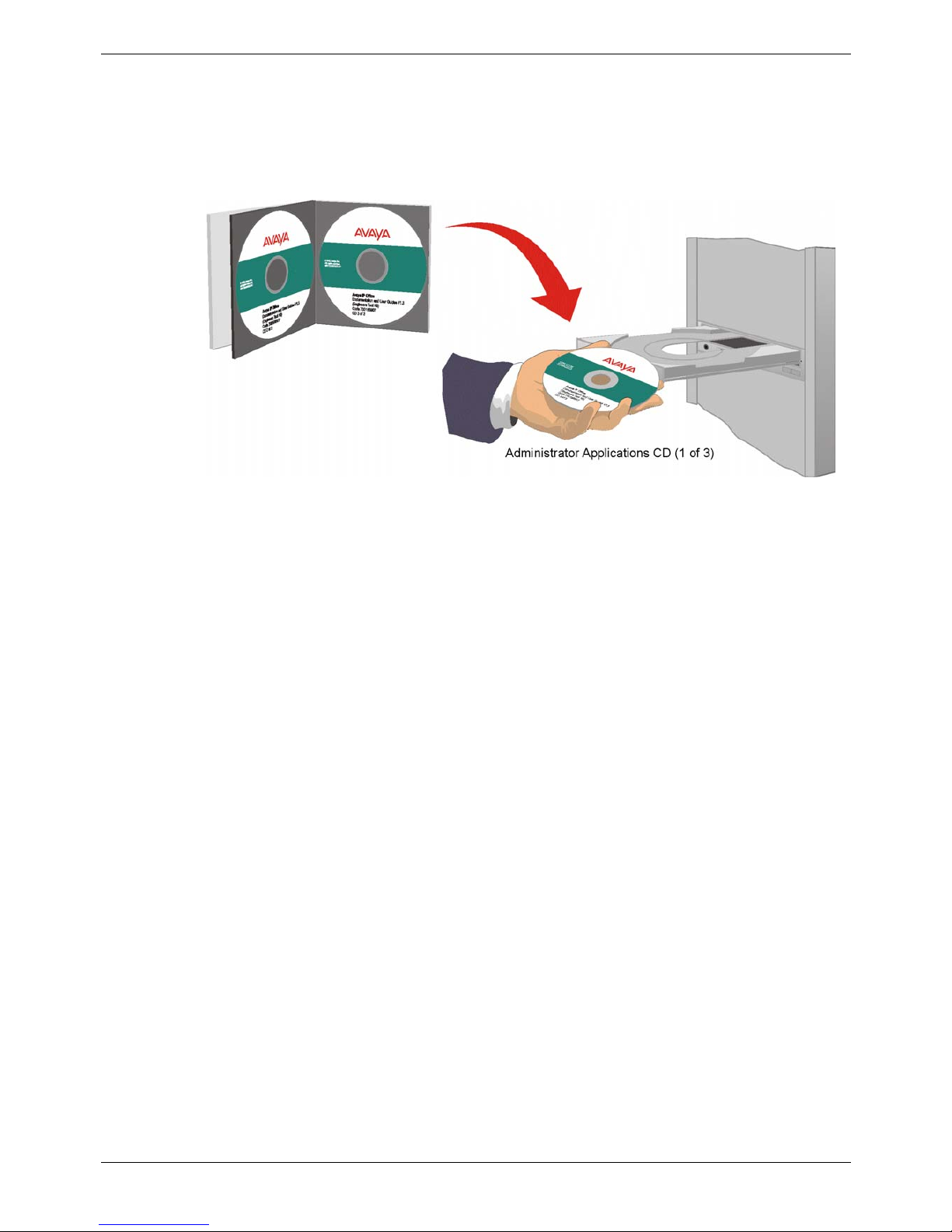
Installing the IP Office Administration Suite
All the software used to configure and manage the IP Office system must be
installed on your PC from the supplied Administrator CD. With the initial assembly
completed (see page 15) and your PC connected to the IP Office system, insert
and run the Administrator (CD 1 of 3) to install Software Level 2.1+ on your PC.
1. The CD Autoruns. You are initially presented with the option to select which
language you wish to use. Select the language from the pull down list and click
OK.
2. If not already installed on your PC, you are then given the option to install the
Microsoft Net 1.1 Framework application. Ignore this for INDeX Media Gateway
The Welcome screen is then displayed; click Next to continue.
3. The Destination folder location option menu is displayed. Either accept the
default location (click on Next) of where the Administration Suite is to be
installed or change the location by clicking on Browse and entering a new
location. Make a note of this location as it is recommended that you use this
later as the location of the Media Gateway IPOData.csv file (see page ).
4. Select which components you wish to install by selecting the appropriate boxes
(Manager and Voice Mail are default minimums) and click Next.
5. Name the program folder or accept the default (IP Office).
6. Click Next and wait for the Administration Suite installation to be completed.
7. Installation runs and on completion select Restart now and click Finish twice.
The IP Office Administration suite of applications is now installed on your PC and
you are now ready to import the data from the INDeX before using the Manager
application to import the INDeX data into the IP Office.
Page 12 - Preparing for Installation Installation Manual
38DHB0002UKGA Issue 1 (12/05/2004) INDeX Media Gateway

Contents - Page 13
Converting the INDeX Database
The INDeX database needs to be downloaded. A data conversion tool is then
used to extract the information, which can then be imported into the IP Office
406/412 platform.
Note: This data must be extracted from the INDeX and imported into the IP Office
406/412 platform before the INDeX system is dismantled.
Download INDeX Database
From the Database Management menu, download and save the INDeX Database.
Running the INDeX Media Gateway conversion file
The following data can be extracted from the INDeX database:
• Extension DN
• Extension Name
• Divert All
• Divert All Status
• Divert No Answer (duplicated for use by Divert Busy)
• Group DN
• Group Name
• Group Members
• Group Ring Mode
The data conversion tool is designed to work on specific versions of INDeX
database. The different versions of the tool are supplied on the IP Office
Administration CD in the directory ‘MG Support’.
To extract the data:
1. Open a command prompt window.
2. Change to the drive or directory containing the conversion tool(s).
3. Enter the name of the tool appropriate for the database and the file name of
the database to be converted i.e. enter 101X-MG <filename.db>. to convert a
database from an INDeX running 10.1 on a CPU-X.
4. If the database is the correct format you are presented with three menu
options:
1. Run Conversion for IP 406
2. Run Conversion for IP 412
3. Quit
5. Select the required option and key CR.
6. The programs runs. You will be asked for the destination folder. It is
recommended that you use the Destination folder location used for the IP
Office Administration suite (see page 12).
7. On completion you are presented with Conversion for IP406/412 successful.
The Destination folder will now contain a file called IPOData.csv, which can
now be loaded into your IP Office.
Installation Manual INDeX Media Gateway Contents - Page 13
38DHB0002UKGA Issue 1 (12/05/2004)

Page 14 - Converting the INDeX Database Pre
Import Database into IP Office
1. Using the IP Office Administration CD, install the IP Office Administration Suite
on your PC (see page 12). Make a note of which directory the IP Office Admin
suite is going to be installed in.
2. Using the Administration CD, run the conversion file mgcon.exe. This will
create a file called IPOData.csv. This file should be stored in the directory
containing the IP Office Admin suite as noted in step 4 above.
3. With the IP Office Manager, use File | Open to open the configuration file for
the IP Office platform. Accept the default settings.
4. In Manager, select File | Import/Export | Import as text.
5. Open the directory where the file IPOData.csv is stored and select Run.
6. On completion, a message Conversion for IP406/412 successful is displayed.
7. From the Manager Configuration Tree items Extension, User and Hunt
Groups you can check that the data from the INDeX has been imported.
8. To update the IP Office database, you must save the configuration. Click on
the File | Save and follow the instructions.
The data retrieved from the INDeX has now been imported into the IP Office
database and you are now ready to configure the IP Office system
Page 14 - Preparing for Installation Installation Manual
38DHB0002UKGA Issue 1 (12/05/2004) INDeX Media Gateway

Contents - Page 15
Installing a New System
Unpacking
Before proceeding with installation, ensure that you have read the instructions in
Preparing for Installation on page 6.
Unpacking and checking:
1. Before unpacking check for any signs of damage that has occurred during
transit. If any damage exists bring it to the attention of the carrier.
2. Check all cartons against the packing slip and ensure that you have the
correct item(s) as per the country variants (see page 43). Report any errors or
omissions to the equipment supplier.
3. While unpacking the equipment, retain all the packaging material. Fault returns
are accepted only if repackaged in the original packaging.
4. Visually inspect each item and check that all the necessary documentation and
accessory items have been included. Report any errors or omissions to the
dealer who supplied the equipment.
5. Ensure you read and understand any documentation included with any item.
An overview of the interconnections for an INDeX Media Gateway is shown on
page 16.
Installation Manual INDeX Media Gateway Contents - Page 15
38DHB0002UKGA Issue 1 (12/05/2004)
Page 16 - Unpacking Ins
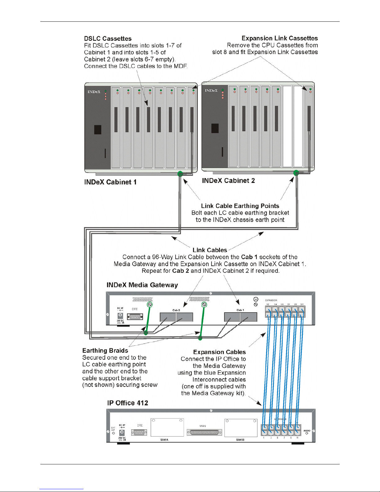
Overview of INDeX Media Gateway Interconnections
Page 16 - Installing a New System Installation Manual
38DHB0002UKGA Issue 1 (12/05/2004) INDeX Media Gateway

Contents - Page 17
INDeX Configuration
The following sequence is recommended for installing the INDeX Media Gateway
into an existing INDeX system.
1. Note and record the extension numbering plan and extension cabling to the
MDF of the existing INDeX system.
2. Make a note of the general programming details of the system.
3. Make sure that the INDeX database has been downloaded, see page 13.
4. Switch off and remove all power from the existing INDeX system.
5. Open the INDeX front cover(s) and remove all cassettes.
6. Insert the required number of DSLC cassettes (maximum of 12) starting from
slot 1 of cabinet 1.
7. Connect the DSLC cassettes to the existing MDF using an INDeX 32 pair
cable. Use the extension/cabling details recorded in step 1 of the installation.
CAUTION: INDeX Media Gateway only uses 30 channels per DSLC, hence
the twisted pairs for channels 31 and 32 become spare.
Installing DSLC Cassettes
This section covers the installation of DSLC cassettes for 20 series terminals.
a. Ensure that you have the correct cassette and a plan of which cassette goes in
each slot. The cassette's label shows its capacity as DSLCx where x is the
number of 20 series terminals supported.
b. Remove the screw at the top of the slot to be used. Insert the new cassette.
c. When power is restored, at the end of the installation process, check which
lamps come on.
– Green On/Red Off: Power supply to cassette okay.
– Green Off: Swap cassette, if the problem persists, check the PSU/CPU.
– Red On: Swap cassette, if the problem persists, check the PSU/CPU.
d. Secure the cassette using its top tab (using the screw previously removed).
e. Connect a 32-pair INDeX cable to the cassette. Attach the cable's P-clip to the
appropriate point at the base of the cabinet for the cassette slot.
f. Cable tie the cable to the front of the cassette.
Installation Manual INDeX Media Gateway Contents - Page 17
38DHB0002UKGA Issue 1 (12/05/2004)

Page 18 - INDeX Configuration Ins
DSLC Cassette Cable Connections
The table below shows the connections from the DSLC cassette to the MDF using
an INDeX 32 pair cable (only 30 pairs used with INDeX Media Gateway). You
must earth the cable screen at the MDF (see page 28). For the connection from
the MDF, each channel requires a Slave Jack Socket (Type LJU 2/3A). The wire
pairs connect to pins 3 & 4.
Ensure that the cable and wires are labelled at both ends.
Channel DSLC-8 DSLC-16 DSLC-24 DSLC-32 Wrap Speech & Data Speech & Data
Channel 1 DSLC DSLC DSLC DSLC Orange White/Blue Blue/White
Channel 2 DSLC DSLC DSLC DSLC Orange White/Orange Orange/White
Channel 3 DSLC DSLC DSLC DSLC Orange White/Green Green/White
Channel 4 DSLC DSLC DSLC DSLC Orange White/Brown Brown/White
Channel 5 DSLC DSLC DSLC DSLC Orange White/Slate Slate/White
Channel 6 DSLC DSLC DSLC DSLC Orange Red/Blue Blue/Red
Channel 7 DSLC DSLC DSLC DSLC Orange Red/Orange Orange/Red
Channel 8 DSLC DSLC DSLC DSLC Orange Red/Green Green/Red
Channel 9 – DSLC DSLC DSLC Orange Red/Brown Brown/Red
Channel 10 – DSLC DSLC DSLC Orange Red/Slate Slate/Red
Channel 11 – DSLC DSLC DSLC Green Black/Blue Blue/Black
Channel 12 – DSLC DSLC DSLC Green Black/Orange Orange/Black
Channel 13 – DSLC DSLC DSLC Green Black/Green Green/Black
Channel 14 – DSLC DSLC DSLC Green Black/Brown Brown/Black
Channel 15 – DSLC DSLC DSLC Green Black/Slate Slate/Black
Channel 16 – DSLC DSLC DSLC Green Yellow/Blue Blue/Yellow
Channel 17 – – DSLC DSLC Green Yellow/Orange Orange/Yellow
Channel 18 – – DSLC DSLC Green Yellow/Green Green/Yellow
Channel 19 – – DSLC DSLC Green Yellow/Brown Brown/Yellow
Channel 20 – – DSLC DSLC Green Yellow/Slate Slate/Yellow
Channel 21 – – DSLC DSLC Brown White/Blue Blue/White
Channel 22 – – DSLC DSLC Brown White/Orange Orange/White
Channel 23 – – DSLC DSLC Brown White/Green Green/White
Channel 24 – – DSLC DSLC Brown White/Brown Brown/White
Channel 25 – – – DSLC Brown White/Slate Slate/White
Channel 26 – – – DSLC Brown Red/Blue Blue/Red
Channel 27 – – – DSLC Brown Red/Orange Orange/Red
Channel 28 – – – DSLC Brown Red/Green Green/Red
Channel 29 – – – DSLC Brown Red/Brown Brown/Red
Channel 30 – – – DSLC Brown Red/Slate Slate/Red
Channel 31
Spare – not used with INDeX Media Gateway
Black/Blue Blue/Black
Channel 32
Spare – not used with INDeX Media Gateway
Black/Orange Orange/Black
Page 18 - Installing a New System Installation Manual
38DHB0002UKGA Issue 1 (12/05/2004) INDeX Media Gateway

Contents - Page 19
Installing the Expansion Link.
1. Insert an Expansion Link Cassette into each slot 8 of the INDeX cabinets and
connect to the INDeX Media Gateway module.
a. Remove the screw at the top of the right-most slot of the cabinet (slot 8)
labelled ELC or CPU Only.
b. If not already done so, remove the CPU-X cassette and insert the
Expansion Link cassette into that slot (slot 8).
c. Secure the cassette (using the screw previously removed) through its top
tab.
d. Plug in the Link Cassette cable(s) from the INDeX Media Gateway
module. Use CAB1 socket for the first INDeX cabinet and CAB2 for the
second cabinet. Link Cable(s). Cable lengths are 2.9mtrs
(38YCN00001SEC) or 1.7mtrs (38YCN00001SEK). The earth braids (two
off) for connection to the INDeX Media Gateway are supplied with the
module.
e. Cable tie the cable to the front of the Link Expansion cassette.
f. Connect the Link Cable earthing clamp to the rear base of the cabinet
slot labelled "ELC/LC".
g. When power is restored, at the end of the installation process, check
which cassette lamps come on.
– Green On/Red Off: Power supply to cassette okay.
– Green Off: Swap cassette, if the problem persists, check the
PSU/CPU.
– Red On: It is normal for ELC Cassettes to display a red lamp until
another cassette is installed in the Expansion Cabinet. If after this the
lamp stays on, swap cassette, if the problem persists, check the
PSU/CPU.
h. Repeat for any other cabinets in the system.
Installation Manual INDeX Media Gateway Contents - Page 19
38DHB0002UKGA Issue 1 (12/05/2004)
Page 20 - INDeX Configuration Ins
Complete INDeX Configuration.
1. Close off the INDeX cabinets.
2. Mount the INDeX Media Gateway and the IP Office modules in their final
location.
3. Connect the Expansion Link Cassette(s) to the INDeX Media Gateway using
Link Cable(s). Ensure that the Link Cables are connected to both the INDeX
cabinet earth and the INDeX Media Gateway earth points. Refer to page 28
for details.
4. For the IP Office modules, ensure that the require trunk interfaces and the
optional integral modules have been fitted.
5. Connect the IP Office module Expansion Ports to the INDeX Media Gateway
Expansion ports. Where IP Office Expansion modules are to be used, also
connect the IP Office module Expansion Ports to these Expansion modules.
6. Proceed with initial programming of the INDeX Media Gateway (see page 26).
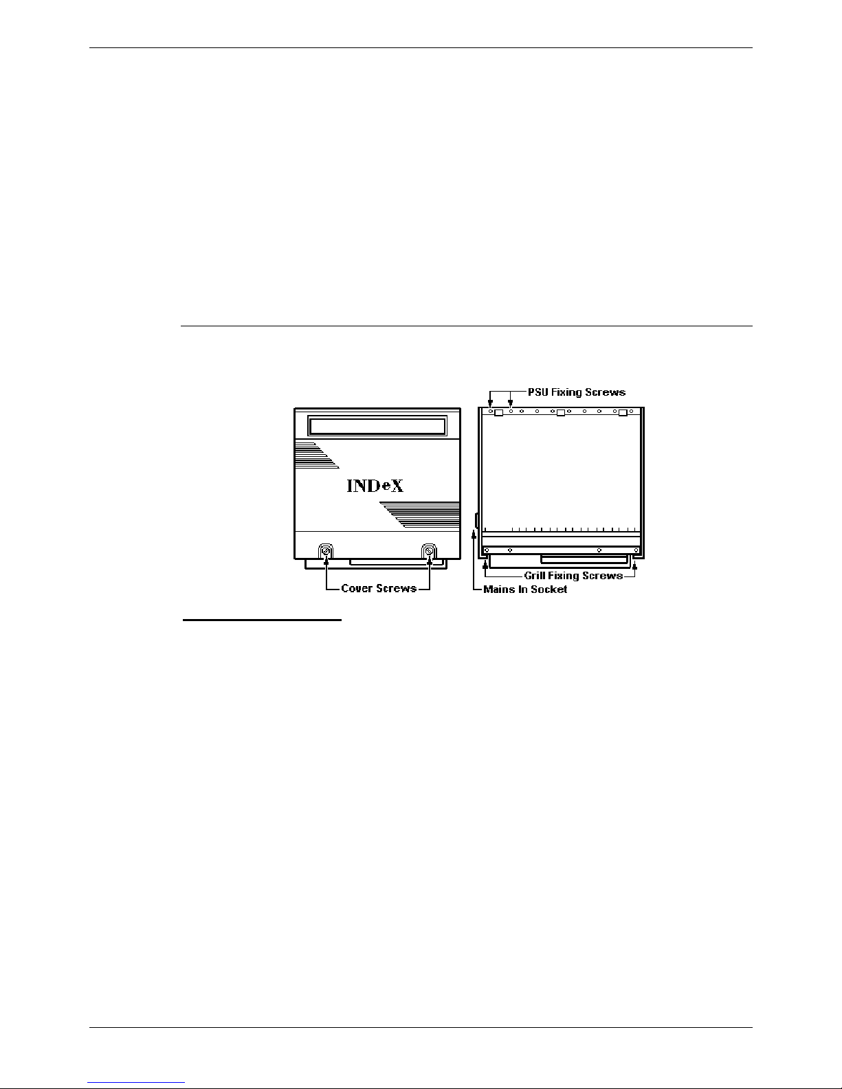
Closing Off the INDeX Cabinet(s)
You must follow the steps below in order to maintain the EMC compliance of the
INDeX system.
To close off a cabinet
:
a. Ensure that each cassette displays just the single green lamp.
b. Check that each cable to the cassettes is clearly labelled and identified.
c. Slide the cabinet grille plate back into the base of the cabinet. Ensure that the
cables all exit the cabinet through the proper cable exit points.
d. Secure the grille plate using the 2 screws previously removed at the start of
installation.
e. Adjust the cable clamp provided at the cable exit point.
f. Hook the front cover back onto the cabinet and secure the two captive cover
screws.
g. Check that none of the cabinet ventilation grills have been blocked.
Page 20 - Installing a New System Installation Manual
38DHB0002UKGA Issue 1 (12/05/2004) INDeX Media Gateway

Contents - Page 21
IP Office Installation
Prior to initial assembly and mounting (rack or free standing) of your INDeX Media
Gateway and IP Office modules, check that the following has been performed:
• The required IP Office Trunk Interface Modules have been installed (see
pages 34, 37 and 22), are of the correct country variant type (see page 44)
and if functional grounding is required (see page 29) that it has been fitted.
• Any optional IP Office Integral Voice Compression and/or Dual Modem
Modules have been fitted (see pages 23 and 24 respectively).
• Where rack mounting is required, that the mounting brackets have been fitted
(see page 25).
• The Link Cable(s) between the INDeX Expansion Link Cassette(s) and the
INDex Media Gateway CAB socket(s) are earthed at both ends (see page
28).
• That the DSLC INDeX cables have been connect to the MDF (see page 18).
• For IP Office Analogue Trunk 16 expansion modules, ensure that the
protective ground is fitted (see pages 42 and 29).
• Where structured cabling is to be used it has been installed, conforms to all
local regulations and is clearly labelled.
Perform the following:
1. Mount the INDeX Media Gateway and the IP Office modules in their final
location (free standing units are ideally stacked one upon another).
2. Run the individual Lump-in-Line PSU cables back to the switchable mains
supply but do not switch-on or connect the PSUs to the IP Office modules.
3. With the exception of a WAN3 module, connect the IP Office base module to
the Expansion Modules using the 1mtr Expansion Interconnect Cables (blue see page 59). These cables run from one of the Expansion Ports on the rear
of a base module to the Expansion Port on the rear of the Expansion Modules.
For WAN3 Modules, use a LAN Interconnect cable (see page 56) running
between one of the LAN Ports on the front of a base unit to the LAN Port on
the front of the WAN3 module.
4. Connect the Trunk Ports on the IP Office base module, using PRI/BRI CAT5E
cables (see page 55), to your provider's trunk sockets.
5. Connect any DT/POT Ports on the front of the IP Office units, using DT Line
Cords (see page 54), to the structured cable sockets. Note that in default, the
lowest port number corresponds to the lowest extension number (201).
6. Connect your PC LAN Port to one of the LAN Ports on the front of an IP Office
base module using a LAN Cable (see page 57).
7. Connect the individual Lump-in-Line PSU to each IP Office module*. Switch on
the INDeX Cabinet(s) first, then the INDeX Media Gateway module, then the
IP Office Expansion modules and finally the IP Office 406/412
Caution: This sequence must be followed. If the IP Office base module does
not detect an item at power on, it will never use it. If power is switched on from
a central point for all modules, then, as the main unit is the slowest to start,
this will be taken care of automatically. A hot-plug ability is not available with
INDeX Media Gateway.
8. From the Administrator CD, install on your PC the software required to
configure and manage your Avaya IP Office. The IP Office System needs to
be programmed, refer to page 26.
Installation Manual INDeX Media Gateway Contents - Page 21
38DHB0002UKGA Issue 1 (12/05/2004)
Page 22 - INDeX Configuration Ins
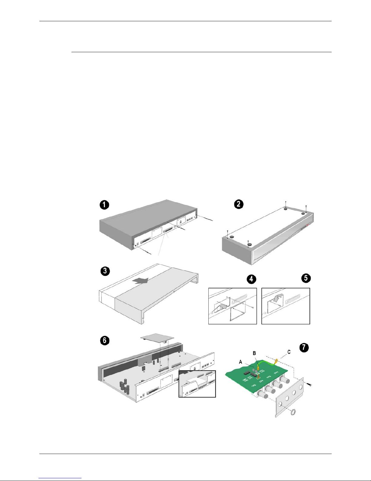
Installation of Integral Modules
To install an integral module in an IP Office system, follow the pictorial instructions
given below:
Trunk Interface Modules (BRI/PRI/ANALOGUE4)
For IP406 see page 34 and for IP412 see page 37.
Procedure
1. Remove the three fixing screws on the rear of cover.
2. Turn the unit over and remove the four fixing screws from the base.
3. Slide the cover from the unit.
4. Remove the two blanking plate securing screws and remove blanking plate.
5. Insert the trunk module and secure with the two screws.
6. Mount the trunk module in position as shown below and secure with the two
snap-in spacers (except for PRI E1/R2).
7. For CALA only: On the PRI E1/R2 coaxial module, use the shorting blocks (A)
to connect Rx1 to GND, Tx1 to GND and/or Rx2 to GND, Tx2 to GND as
required. Connect the earthing strap spade end (B) to the spade connection
on the board and the other end (C) to the chassis with the long securing screw
(both of which are supplied with the kit).
8. Where required, fit the functional ground (see page 29).
9. Replace cover and secure with the seven fixing screws.
CAUTION: While installing, ensure that you wear a ground wrist strap that is
connected to a suitable grounding point.
Page 22 - Installing a New System Installation Manual
38DHB0002UKGA Issue 1 (12/05/2004) INDeX Media Gateway
 Loading...