

Avaya IG550 Quick Start Manual

Quick Start
for Hardware Installation:
IG550 Integrated Gateway
Preparing before you go on-site . . . . . . . . . . . . 3
Getting ready on-site . . . . . . . . . . . . . . . . . . 3
Upgrading J-series router software, if necessary . . . 4
Verifying the router has the power for the TIMs and PIMs 4
Installing hardware . . . . . . . . . . . . . . . . . . . 4
Loading Disk on Key, if available. . . . . . . . . . . . 9
Connecting the LAN and your laptop after
using Disk on Key . . . . . . . . . . . . . . . . . . . 11
Finish configuring the router after using Disk on Key 12
Installing an IG550 Integrated Gateway using the J-Web
Quick Configuration interface . . . . . . . . . . . . . 12
Configuring the router using the CLI, if you
did not use J-Web Quick Configuration . . . . . . . 13
Configuring the TGM550 . . . . . . . . . . . . . . . . 17
03-601553
Issue 2
January 2008


Preparing before you go on-site
1. Check Juniper software compatibility with TGM550 Gateway Module
firmware. See http://support.avaya.com
.
2. Download the most recent firmware for the TGM550. See http://
support.avaya.com.
3. Ensure the customer has an FTP or TFTP server that is accessible to the
TGM550. If not, download a TFTP server to your laptop.
4. Review safety requirements and airflow requirements. See Installing and
Configuring the IG550 Integrated Gateway.
5. Get the tools you need:
● Electrostatic discharge (ESD) grounding strap
● Flathead and Phillips head screwdrivers
Getting ready on-site
1. Verify you have:
● The Juniper Services Router (J2320, J2350, J4350 or J6350)
● A 10 AWG grounding cable
● An AC or 14 AWG DC power cable
● Cables for the TGM550, Telephony Interface Modules (TIMs), and
Physical Interface Modules (PIMs)
!
CAUTION:
CAUTION: You cannot use a 14 AWG grounding ca ble with the rout er. The
grounding cable must be 10 AWG.
● A USB modem
● Two distinct and different console cables:
- An RJ-45 flat rollover cable and a DB-9 adapter for console
connections to the TGM550
- An ordinary round RJ-45 Ethernet cable and a DB-9 adapter for
console connections to the Juniper router
Issue 2 January 2008 3

Upgrading J-series router software, if necessary
Note:
Note: The software of the Juniper Services Router must match the
firmware version of the TGM550. See the Communication
Manager Software/Firmware Compatibility Matrix under
Downloads on support.avaya.com.
1. See the Juniper J2320, J2350, J4350, and J6350 Services Router Getting
Started Guide, Release 8.4.
Verifying the router has the power for the TIMs and PIMs
Verify that the project manager, sales representative, or sales engineer has
ordered the appropriate quantity and types of TIM and PIM modules for the
router you are installing. If not, see "TIM and PIM limits based on heat and
power used by the IG550" in Overview of the Avaya IG550 Integrated
Gateway, 03-601548.
Installing hardware
1. If the customer has a four-post rack and is using a shelf, install the shelf
according to manufacturer guidelines. If the customer is using the
4 Quick Start for Hardware Installation: IG550 Integrated Gateway
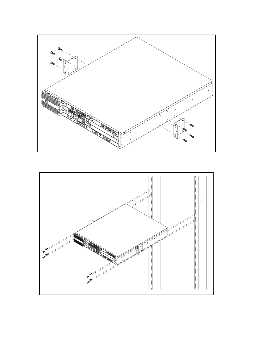
brackets supplied with the router , inst all the bracket s on the chassis of the
Juniper Services router midway between the front and back.
Juniper
NET
A
LM
W
Gateway
OR
ACT
KS
TGM55
0
AL
M
Analog
ACT
TIM514
RST
Console
ASB
ALM
E1/T1
ACT
1234
ETR
TST
TIM510
SIG
Lin
1234
e
POWER
STATUS
LineTrunk
SO EI SM
ALARM
HA
Line5678
POWER
EM SI EO
RESET
CON
FIG
ALM
BRI
ACT
TIM5
T
21
X
/
R
X
0
/
0
L
I
N
K
T
X
/
R
X
0
/
1
L
I
N
1
K
0
T
/
X
1
/
R
0
X
0
/1
0
0
/
0
2
0
L
I
N
K
T
X
/
R
X
1
0
/
3
L
I
N
K
2
3
CONSOLE
4
AUX USB
0
1
1
2
3
4
5
6
J4350
qsmabrkt LAO 092906
2. Install the router on the rack.
Juniper
N
E
A
L
T
M
W
G
a
O
t
AC
e
R
way
K
T
S
T
G
M
5
5
0
A
L
M
A
n
a
AC
l
o
g
T
T
I
M
5
R
1
C
S
4
o
A
T
n
S
s
B
o
l
e
A
L
M
E
1
/
AC
T
1
1
E
T
T
T
S
R
T
T
I
M
5
1
2
S
0
I
G
L
1
i
n
Tru
e
n
3
k
2
POWER
4
3
STATUS
L
i
n
S
e
O
5
4
ALARM
E
I
HA
6
S
M
L
i
n
P
e
E
O
M
W
7
E
R
S
I
A
L
8
M
R
B
E
E
R
O
S
I
AC
C
E
O
T
T
N
T
F
I
I
M
G
5
T
2
X
/R
1
X
0
/
0
L
IN
K
T
X
/R
X
0
/
1
L
IN
1
K
0
T
/
X
1
/
R
0
X
0
/
1
0
0
/
0
2
0
L
I
N
K
T
X
/
R
X
1
0
/
3
L
I
N
K
2
3
C
O
N
S
O
L
E
4
AU
X
0
1
U
S
B
1
2
3
4
5
6
J4350
3. Be sure the power to the router is off.
qsmarack LAO 092906
Issue 2 January 2008 5

!
Line
34
CAUTION:
CAUTION: The Juniper Services Router must be turned off before inserting
or removing the Avaya TGM550, TIM modules, or PIM
modules. These modules are not hot-swappab le. If you attempt
to remove or insert these modules while the router is turned on,
the router might reset or malfunction in some other way.
4. Insert the TGM550 and each TIM, PIM, ePIM, or uPIM into the correct
slot. If the slots are already administered on the Communication Manager
server, the slots you use must match the Communication Manager
administration. The TGM550, TIMS, and uPIMs can be inserted into any
slots. Other PIMs and ePIMs might have limitations. See "Inserting the
TGM550, the TIMs, and the PIMs in the router, if necessary" in Installing
and Configuring the Avaya IG550 Integrated Gateway, 03-601554.
5. Align the notches in the connector at the rear of the TGM550, TIM, or PIM
with the notches in the slot in the router. Then slide the module in until it
lodges firmly in the router.
!
CAUTION:
CAUTION: Carefully slide the module straight into the slot to avoid
damaging the connector components.
Juniper
NETWORKS
ALM
Analog
ACT
TIM514
ALM
E1/T1
ALM
Gateway
ACT
TGM550
ACT
TST
TIM510
SIG
Line1234
POWER
STATUS
SO EI SM EM SI EO
ALARM
RST
Console
ASB
ETR
1234
HA
LineTrunk
Line5678
POWER
RESET
CONFIG
TX/RX
0
/0
0
/1
LINKTX/RXLINK TX/RX LINKTX/RX
1
0
/1
0
ALM
BRI
ACT
TIM521
0
/1
0
0
/2
0
0
0
/3
LINK
CONSOLE AUX USB
1
0
1
1
2
3
6. Cable the TIMs and PIMs.
● TGM550 — CAT5 harness cables with RJ11 connectors
● TIM508 — A B25A unshielded 25-pair amphenol cable
6 Quick Start for Hardware Installation: IG550 Integrated Gateway
2
3
4
4
5
6
J4350
h LAO 1003063macrdr
 Loading...