

Page 1

Installing the Avaya S8500 Media Server
with the Avaya G650 Media Gateway
555-245-107
Issue 1.1
December 2003
Page 2

Copyright 2003, Avaya Inc.
All Rights Reserved
Notice
Every effort was made to ensur e that the in forma tion in this do cume nt
was complete and accurate at the time of printing. However,
information is subject to change.
Warranty
Avaya Inc. provides a limited warranty on this product. Refer to your
sales agreement to establish the terms of the limited warranty. In
addition, Avaya’s standard warranty language as well as information
regarding support for this product, while under warranty, is available
through the following Web site: http://www.avaya.com/support
Preventing Toll Fraud
“Toll fraud” is the unauthorized use of your telecommunications
system by an unauthorized party (for example, a person who is not a
corporate employee, agent, subcontracto r, or is not working on your
company's behalf). Be aw a re t h at the re ma y be a risk of toll fraud
associated with your system and that, if toll fraud occurs, it can result
in substantial additional charges for your telecommunications
services.
Avaya Fraud Intervention
If you suspect that you are being victimized by toll fraud and you need
technical assistance or support, in the United States and Canada, call
the Technical Service Center's Toll Fraud Intervention Hotline at
1-800-643-2353.
How to Get Help
For additional support telephone numbers, go to the Avaya support
Web site: http://www.avaya.com/support
• Within the United States, click the Escalation Management link.
Then click the approp ria t e li nk for the type of support you need.
• Outside the Unit ed States, click th e Escalation Management link.
Then click the International Services link that includes telephone
numbers for the internationa l Centers of Excellence.
Providing Telecommunications Security
Telecommunications security (of voice, data, and/or video
communications) is the prevention of any type of intrusion to (that is,
either unauthorized or m al ic io us access to or use of) your company's
telecommunications equipment by some party.
Your company's “t elecommunicatio n s equipment” includes both this
Avaya product and any other voice/data/video equipment that could be
accessed via this Avaya product (that is, “networked equipment”).
An “outside party” is an yone who is not a corporate employee, agent,
subcontractor, or is not working on your company's behalf. Whereas, a
“malicious party” is anyone (in cl udi ng someone who may be
otherwise authorized) who accesses your telecommunications
equipment with eit her malicious or mischievous i n te nt .
Such intrusions may be either to/throu gh sync hronous (timemultiplexed and/or circ uit -ba sed) or asynchronous (character-,
message-, or packet-based) equi pm ent or interfaces for reasons of:
• Utilization (of capabilities special to the accessed equipment)
• Theft (such as, of intellectual property, financial assets, or toll
facility acces s )
• Eavesdropping (privacy invasions to humans)
• Mischief (troubling, but a ppa re ntl y in noc uous, tampering)
• Harm (such as harmful tampering, data loss or alteration,
regardless of motive or intent)
. If you are:
.
Be aware that there may be a ri sk of unauthorized intrusions
associated with your syste m a nd/ or it s net w orked equipment. Also
realize tha t, if such an intru s ion should occ u r, it could result in a
variety of losses to your company (including but not limit ed to,
human/data privacy, intellectual property, material assets, financial
resources, labor costs, and/or legal costs).
Responsibility for Your Company’s Telecommunications Security
The final responsibility for securi ng both this system and its
networked equipmen t re sts wit h you - Avaya’s customer system
administrator, your telecommunications pe e rs, a nd your managers.
Base the fulfillment of your responsibility on acquired knowledge and
resources from a variety of sources incl udi ng but not limited to:
• Installation docu ments
• System administration documents
• Security documents
• Hardware-/so ft w ar e-based security t ool s
• Shared information between you and your peers
• Telecommunications security experts
To prevent intrusions to your telecommunications equipment, you and
your peers should carefully pro gra m a nd c onfi gure:
• Your Avaya-provided telecommunications systems and their
interfaces
• Your Avaya-provided software applications, as well as their
underlying hardw ar e/software platforms an d int erfaces
• Any other equipment networked to your Avaya products
TCP/IP Facilities
Customers may experience difference s in product performance,
reliability and security depending upon network configurations/design
and topologies, even when the product performs as warranted.
Standards Compliance
Avaya Inc. is not responsible for any radio or television interference
caused by unauthorize d modifications of this equipment or the
substitution or attachment of connecting cables and equipment othe r
than those specified by Avaya Inc. The correction of interference
caused by such unauth orized mo dificati ons, subs tituti on or atta chment
will be the responsi bili ty o f the u ser. Pursuan t to Part 15 of the Federal
Communications Commission (FCC) Rules, the user is cautioned that
changes or modifications not expressly approved by Avaya Inc. could
void the user’s authority to operate this equipment.
Product Safety Standards
This product complies with and conforms to the following
international Product Safety standards as applicable:
Safety of Information Technology Equipment, IEC 60950, 3rd Edition
including all relevant national deviations as listed in Compliance with
IEC for Electrical Equipment (IECEE) CB-96A.
Safety of Information Technology Equipment , CAN/CSA-C22.2
No. 60950-00 / UL 60950, 3r d Edition
Safety Requirements for Custom e r Equipment, ACA Technical
Standard (TS) 001 - 1997
One or more of the following Mexican national standards, as
applicable: NOM 001 SCFI 19 93, N O M SCFI 016 1993, NOM 019
SCFI 1998
The equipment described in this doc um e nt m ay con ta in Class 1
LASER Device(s). These devices comply with the following
standards:
• EN 60825-1, Edition 1. 1, 1998-01
• 21 CFR 1040.10 and CFR 1040 .11.
Page 3

The LASER devices op erate within the followi ng pa rameters:
• Maximum power output : -5 dB m to -8 dBm
• Center Wavelength: 1310 nm to 1360 nm
Luokan 1 Laserlaite
Klass 1 Laser Apparat
Use of controls or adjustmen ts or pe rformance of procedures oth er
than those specified herein may result in hazardous radiation
exposures. Contact your Avaya representative for more laser product
information.
Electromagnetic Compatibility (EM C ) Standards
This product complies w it h and conforms to the following
international EMC standa rds and all relevant national deviati ons:
Limits and Methods of Measurement of Radio Interference of
Information Technology Equipment, CISPR 22: 1997 and
EN55022:1998.
Information Technology Equipment – Immunity Cha ra ct er istic s –
Limits and Methods of Measurement, CISPR 24:1997 and
EN55024:1998, including:
• Electrostatic Discharge (ESD) IEC 61 000-4-2
• Radiated Immunity IEC 61000-4-3
• Electrical Fast Transient IEC 61000-4-4
• Lightning Effects IEC 61000-4-5
• Conducted Immunity IE C 61000-4-6
• Mains Frequency Magnetic Field IEC 61000-4-8
• Voltage Dips and Variations IEC 61000-4-11
• Powerline Harmonics IEC 610 00-3-2
• Voltage Fluctuations and Flicker IEC 61000-3-3
Federal Communications Commission Statement
Part 15:
Note: This equipment has been tested and found to comply with
the limits for a Class A digital device, pursuant to Part 15 of the
FCC Rules. The s e limits are designed to provide reasonable
protection against h a r m ful interference when the equipment is
operated in a commercial environment. This equipment generates,
uses, and can radiate radio frequency energy and, if not installed
and used in accordance with the instruction manual, may cause
harmful interferenc e to radio communications . Op eration of this
equipment in a residential area is likely to cause harmful
interference in w h ic h case the user will be req u ired to c o rrect the
interference at his own expense.
Part 68: Answer-Supervision Signaling
Allowing this equipm ent to be operated in a man ner that does not
provide proper answer-supervision sig na ling is in violation of Part 68
rules. This equipment returns answer-supervision signals to the public
switched network when:
• answered by the called station,
• answered by the attendant, or
• routed to a recorde d an n ou ncement that can be admin i stered by
the customer premises equipment (CPE) user.
This equipment returns answer-supervision signals on all direct
inward dialed (DID) calls forwarded back to the public switched
telephone network. Permissi bl e exceptions are:
• A call is unanswered.
• A busy tone is received.
• A reorder tone is rece ived.
Avaya attests that this registered equipment is capabl e of providing
users access to int erstate providers of operato r services th rough the us e
of access codes. Modification of this equipment by call aggregators to
block access dialing codes is a violation of the Telephone Operator
Consumers Act of 1990.
REN Number
For MCC1, SCC1, CMC1, G600, and G 650 M e d ia Gat eways:
This equipment complie s with Part 68 of the FCC rules. On either the
rear or inside the front cover of this equipment is a label that contains,
among other information, the FCC registration number, and ringer
equivalence numb er (R EN ) for this equipment. If requested, this
information must be provided to the telephone company.
For G350 and G700 Media Gateways:
This equipment complie s with Part 68 of th e F C C rules and the
requirements adopted by the ACTA. On the rear of this equipment is a
label that contains, among other information, a product i de nti fi er in
the format US:AAAEQ##TXXXX. The digits represented by ## are
the ringer equivalence number (REN) without a decim al p oin t (fo r
example, 03 is a REN of 0.3). If requested, this number must be
provided to the tel ephone company.
For all media gateways:
The REN is used to determine the qua ntity of devices that may be
connected to the telephone line. Excessive RENs on the telephone line
may result in devices not ringing in response to an incoming call. In
most, but not all areas, the sum of RE Ns should not exceed 5.0. To be
certain of the num ber of devices that may be connected to a line, as
determined by the total RENs, contact the local telephone company.
REN is not required for some t ype s of ana l og or digital facilities.
Means of Connection
Connection of this equipment to the telephone network is shown in the
following tables.
For MCC1, SCC1, CMC1, G600, and G 650 M e d ia Gat eways:
Manufacturer’s Port
Identifier
Off premises station OL13C 9.0F RJ2GX,
DID trunk 02RV2-T 0.0B RJ2GX,
CO trunk 02GS2 0.3A RJ21X
Tie trunk TL3 1M 9.0F RJ2G X
Basic Rate Int e r face 0 2I S 5 6.0F, 6.0Y RJ49C
1.544 digital interface 04DU9-BN 6.0F RJ48C,
120A4 channel servic e unit 04DU9-DN 6. 0Y RJ48C
FIC Code SOC/REN/
A.S. Code
02LS2 0.3A RJ21X
04DU9-IKN 6.0F RJ48C,
04DU9-ISN 6.0F RJ48C,
Network
Jacks
RJ21X,
RJ11C
RJ21X
RJ48M
RJ48M
RJ48M
Page 4
For G350 and G700 Media G ate w ays:
Manufactur er’s Port
Identifier
Ground Start CO trunk 02GS2 1.0A RJ11C
DID trunk 02RV2-T AS.0 RJ11C
Loop Start CO trunk 02LS2 0.5A RJ11C
1.544 digital interface 04DU9-BN 6.0Y RJ48C
Basic Rate Interface 02IS5 6.0F RJ49C
For all media gateways:
If the terminal equipment (for examp le , the media server or me dia
gateway) causes harm to the tel e phone network, the telephone
company will notify you in advance that temporar y di scontinuance of
service may be require d. But if advance notice is not practical, the
telephone company will notify the customer as soon as possible. Also,
you will be advised of your right to file a complaint with the FCC if
you believe it is necessary.
The telephone company may make changes in its facilities, equipment,
operations or procedures tha t co uld affect the operation of the
equipment. If this hap p e ns, t he telephone company will provide
advance notice in order for you to ma ke nec essa ry m odifications to
maintain uninterrupted service.
If trouble is experienced w i th t his equipment, for repair or warrant y
information, plea s e contact the Technical Service Center at
1-800-242- 2121 or contact your local Avaya representative. If the
equipment is causing ha rm to the telephone network, the telephone
company may request tha t you disconnect the equipment until the
problem is re s olved.
A plug and jack used to connect this equipment to the premises wiring
and telephone network must comply with the applicable FCC Part 68
rules and requirements adopted by the ACTA. A compliant telephone
cord and modular plug is provided with this product . It is designed to
be connected to a co mp atible modular jack th at is also compliant . I t is
recommended that repairs be performed by Avaya certified
technicians.
The equipment cannot be use d on public coin phone service provided
by the telephone com pany. Connection to party line service is subject
to state tariffs. Contact the state public utility commission, public
service commission or corporation commission for information.
This equipmen t, if it uses a telephone receiver, is hearing aid
compatible.
FIC Code SOC/REN/
A.S. Code
04DU9-DN 6.0Y RJ48C
04DU9-IKN 6.0Y RJ48C
04DU9-ISN 6.0Y RJ48C
Network
Jacks
Declarations of Conformity
United States FCC Part 68 Supplier ’s Declaration of Conform ity
(SDoC)
Avaya Inc. in the United States of America hereby certifies that th e
equipment describe d in thi s document and bearing a TIA TS B-168
label identi f ication number complies with the FCC’s Rules and
Regulations 47 CFR Part 68, an d the A dm inistrative Council on
Terminal Attachments (ACTA) adopted technical criteria.
Avaya further asserts that Avaya handset-equipped terminal
equipment described in this document complies wi th Pa ragraph
68.316 of the FCC Rules and Regu lati ons de fi ning Hearing Aid
Compatibil ity and is deeme d compatible with hearing aids.
Copies of SDoCs signed by the Responsible Par ty in the U. S. ca n be
obtained by contacting your local sales representative a nd a re
available on the following Web site: http://www.avaya.com/support
All A vay a me dia s erv ers an d me dia ga te way s are compl ia nt wi th FCC
Part 68, but many have been registered with the FCC before the SDoC
process was available. A list of all Avaya registered products may be
found at: http://www.part68.org
as manufacturer.
European Union Declarations of Conformity
Avaya Inc. declares that the equipment spec ified in this docum ent
bearing the “CE” (Conformité Europeénne) mark conforms to the
European Union Radio and Telecommunications Terminal Equipment
Directive (1999/5/EC), including the Electromagnetic Compatibility
Directive (89/336/EEC) and Low V oltage Directive (73/23/EEC). This
equipment has been certified to meet CTR3 Basic Rate Interface (BRI)
and CTR4 Primary Rate Interface (PRI) and subsets thereof in CTR12
and CTR13, as applicable.
Copies of these Declarations of Conformity (DoCs) can be obtained
by contacting your local sale s representative and are avai la bl e on the
following Web site: http://www.avaya.com/support
Japan
This is a Class A product based on the standard of the Voluntary
Control Council for Interfe rence by Information Technology
Equipmen t ( V CCI). If this equipment is us ed in a domestic
environment, radio disturbance may occur, in which case, the user
may be required to take co rrective actions.
by conducting a search using “Avaya”
.
.
Canadian Department of Communications (DOC) Interfe rence
Information
This Class A digital appar at us complies with Canadian ICE S -003.
Cet appareil numérique de la classe A est conforme à la norme
NMB-003 du Canada.
This equipment meets t he applicable Industry Canada Terminal
Equipment Technical Specifications. This is confirmed by the
registration number. The abbreviation, IC, be fore the registration
number signifies that registration was perform e d based on a
Declaration of Conformi ty i ndicating that Industry Canada tec hni cal
specifications were met. It does not imply that Industry Canada
approved the equipment.
To order copies of this and other documents:
Call: Avaya Publications Center
Voice 1.800.457.1235 or 1.207.866.6701
FAX 1.800.457.1764 or 1.207.626.7269
Write: Globalware Solutio ns
E-mail: [email protected]
For the most current versions of documentation, go to the Avaya
support Web site: http://www.avaya.com/support
200 Ward Hill Avenue
Haverhill, MA 01835 USA
Attention: Avaya Account Management
.
Page 5

Contents
About this book 15
•Overview 15
• Audience 15
• Using this documentation 15
• Conventions 16
General 16
Physical dimensions 16
Terminology 17
Typography 17
Commands 17
Keys 17
User input 18
Contents
System output and field names 18
• Downloading this book and updates from the Web 18
Downloading this documentation 19
• Safety labels and security alert labels 19
• Safety precautions 20
• Related sources 22
• Technical assistance 23
Within the US 23
International 23
• Trademarks 23
• Sending us comments 23
Installing the Avaya S8500 Media Server
with an Avaya G650 Media Gateway 25
• Pre-Installation Setup 26
• Avaya S8500 Media Server features and specifications 28
• High level overview of installation process 30
Installing the media server complex 30
Installing Release 2.0 of Avaya Communication Manager 30
Configuring the Remote Supervisor Adapter 30
Configuring the media server 31
Customizing the media server 31
Installing the media gateways 31
Installing the Avaya S8500 Media Server with an Avaya G650 Media Gateway 5
December 2003
Page 6

Contents
Cabling the media gateways 31
Connecting the media gateways 31
Connecting to the customer’s network 31
Installing and wiring telephones 31
Completing the installatio n 32
Testing the complete installation 32
• Downloading license and Avaya authentication files 33
RFA information requirements for new installations 34
Going to the RFA Web site 34
• Installing the Avaya S8500 Media Server 35
Considerations 35
Required tools 35
Installing the Avaya S8500 Media Server 35
Remote Supervisor Adapter components 37
• Mounting hardware in the rack 38
Avaya S8500 Media Server components 38
• Installing the network interface card 39
Backing up the media server 40
Powering down the media server 41
Removing the cover of the media server 41
Removing the fan unit 42
Installing the small faceplate on the network interface card 42
Inserting the network interface card 43
Replacing the fan unit 44
Replacing the cover and cabling 44
Powering up the media server 45
Checking LED activity on network interface card 45
Confirming original Eth er net con fig ur ation 46
Configuring the NIC 46
Testing connectivity to customer’s network 47
• Remote Supervisor Adapter components 48
• Connecting the modems 49
• Configuring and connecting the hardware 51
• Configuring the media server 52
Copying files to the laptop 52
Powering up the media server 53
Accessing the media server 53
Clearing the ARP cache on the laptop 53
6 Installing the Avaya S8500 Media Server with an Avaya G650 Media Gateway
December 2003
Page 7

Contents
Setting up Telnet 53
Installing the software 54
Using the Installation Wizard 56
Completing the Remote Supervisor Adapter configuration 58
Checking LED activity on the network interface card 58
Verifying media server connection to the customer’s LAN (if provided) 58
Disconnecting from the media server 59
• Configuring the Remote Supervisor Adapter 60
Before you get started 61
Obtaining Avaya Registration Tool information 61
Remote Supervisor Adapter power 61
LAN and serial port connectivity 61
Connecting and logging in to the Remote Supervisor Adapter 62
Configuring the Remote Supervisor Adapter 63
Changing login ID and password 64
Configuring Advanced System Management 66
Setting alarms 68
Configuring network interfaces 70
Configuring network protocols 71
Backing up the configuration 72
Restoring Advanced System Management configurations 74
Modifying a file 75
Setting auto answer on the RSA card 75
Updating RSA or BIOS firmware 76
Logging off the Remote Supervisor Adapter 77
• Configuring the network interface card 78
Confirming original Eth er net con fig ur ati on 78
Configuring the NIC 78
Testing connectivity to customer’s network 79
• Configuring the modem 80
• Configuring the SNMP modules in the uninterruptible power supplies 84
Simplex reliability configurations 85
Setting selected traps (alarming) 86
• Configuring the SNMP subagent in the Avaya Ethernet switch (if used) 87
• Customizing the media server 89
Starting terminal emulation 89
Inputing translations 89
Resetting media server 90
Installing the Avaya S8500 Media Server with an Avaya G650 Media Gateway 7
December 2003
Page 8

Contents
Adding media gateways 90
Administering the IP server interface 90
Adding IPSI information 91
Setting IPSI duplication (high/critical reliability only) 93
Setting alarm activation level 93
Installing the translation file 93
Saving translations 93
• Installing the media gateways 94
Checking and inspecting the order 96
Checking the customer’s order 96
Unpacking and inspecting the media gateways—G650 96
Checking circuit packs 97
Unpacking and inspecting the media gateways—MCC1 98
Correcting shipping errors 98
Connecting AC power and ground 99
Approved grounds 99
Installing the G650 Media Gatew ay 100
Checking circuit packs 103
Checking the ventilation and the G650 Media Gateway rack 105
Setting the carrier address ID 106
Mounting one G650 Media Gateway 108
Mounting two to five G650 Media Gateways 112
Installing the TN2312BP IPSI adapter 112
Approved ground 113
Connecting the G650 Media Gateway grounds and other grounds 113
AC power 115
DC power 117
Uninterruptible power supply 118
G650 Media Gateway power switch 119
Cabling the G650 Media Gateways 121
Cabling two media gateways 121
Cabling the third media gateway 122
Cabling the fourth media gateway 122
Cabling the fifth media gateway 123
Installing circuit packs in the G650 Media Gateway 124
Installing an MCC1 Media Gateway 126
Positioning and bolting down for earthquakes 128
How much AC power? 131
Global AC Power Distribution Unit J58890CH 131
8 Installing the Avaya S8500 Media Server with an Avaya G650 Media Gateway
December 2003
Page 9

Contents
Wiring Block Diagram 140
DC Power Distribution Unit J58890CF 150
AC Power Distribution Unit J58890CE 153
Connecting mixed AC/DC power and ground 158
Cabling the MCC1 Media Gateways—center stage switch 159
Connecting fiber optic cables 159
Connecting duplex- or high-reliability
center stage switch-connected PN1 with one switch node 160
Connecting critical reliability CSS-connected
PN1 with one switch node 161
Installing the G350 M edia Gateway 163
Installing the G700 M edia Gateway 165
Installing patch panels 167
Cross-connecting the media gateway to the patch panels 167
• Installing the main distribu tion frame 170
Space requirements and layout 171
Installation space requirements 171
Layout 171
Installing main dist ribution frame hardw are 174
Main distribution frame cross-connect fields 176
Placing the main distribution frame 176
Main distribution frame labels 178
Mounting 110A- or 110P-type terminal blocks on the wall 179
Mounting 110P-type terminal blocks on a frame 181
Installing Cable Slac k Managers 183
• Connecting the media gateway to the main distribution frame 185
Equipment room cabling labels 185
Cable routing guidelines 187
Trunk cables among network interface,
sneak fuse panel, and media gateway 189
Installing cables between media gateway and main distribution frame 189
Installing connector cables between auxiliary
cabinet (if used) and main distribution frame 189
• Connecting the main distribution frame to stations and
the public switched telephone network 191
Station (telephone) wiring desig n 1 91
Information outlets 191
Station cables 191
Closets 193
Satellite locations 193
Installing the Avaya S8500 Media Server with an Avaya G650 Media Gateway 9
December 2003
Page 10

Contents
Site locations 194
Station circuit distribution from equipment room 194
4-pair station circuits 195
3-pair to 4-pair station circuit distribution 195
Connected cable station adapters 200
Completing a provisioning plan 202
Installing sneak current and off premise protection 204
Installing sneak fuse panels 207
Installing the coupled bonding conductor 208
Installing coupled bonding conductor wires 208
Installing and administering the patch cord/jumper 210
Labeling expansion control carrier cable
(MCC1 Media Gateway only) 212
Connecting expansion control carrier outputs
cable (MCC1 Media Gateway only) 213
Connecting trunk pairs using concentrator cables 213
Connecting trunk pairs to media gateway
using jumper wires to establish 3-pair modularity 215
• Avaya RSA defaults 217
• Connecting to the IP server interfaces 222
Connecting to the internet protocol service interface circuit packs 222
Programming the internet protocol service interface circuit packs 222
Verifying that IPSIs are translated 227
Verifying connectivity to media server 227
Upgrading IPSI firmware versio n (if neces sar y) 227
Enabling control of IPSIs 228
Verifying license status 228
• Connecting to the customer’s network 229
Avaya S8500 Media Server 229
TN799DP Control LAN 230
TN2302AP IP Media Processor 230
TN801B MAP-D LAN Gateway 230
TN2501AP Voice Announcement over LAN (VAL) 230
Important file specifications 231
Caveats 231
• Installing and wiring telephones and trunks 232
Wiring telephones and trunks 232
Connecting telephones 233
Connectable telephone s and co ns ole s 233
10 Installing the Avaya S8500 Media Server with an Avaya G650 Media Gateway
December 2003
Page 11

Contents
Connecting a typical telephone 234
Connecting adjunct power 235
Connecting an analog station or 2-wire digital station 236
Analog tie trunk example 237
Digital tie trunk example 238
DS1 tie trunk example 239
Collocated DS1 interface trunks 239
DS1 interface trunks using T1 channel service unit 239
Auxiliary connector outputs (MCC1 and
Media Gateways only) 242
Three-pair and four-pair modularity 245
Adjunct power connection locations 246
Attendant console example 247
Attendant console cabling distances, local
and phantom power 247
Auxiliary power 247
Hard-wire bridging 248
Dual wiring of 2-wire and 4-wire endpoints 248
Installing the attendant console 248
Installing the 26B1 Selector Console 248
Connecting external alarm indicators and auxiliary power 248
Connect Power Distribu tion Unit External Alarm Wires 250
Installing off-premises station wiring 252
Off-premises or out-of-building stations 253
Off-premises connections 253
Off-premises protection requirements 255
Telephone restrictions for exposed environments 256
Digital Out-of-Building Telephone Protection 256
Emergency transfer units and associated telephones 258
808A Emergency Transfer Panel and
telephone installation examples 259
Installing the 808A Emergency Transfer Panel 260
Installing telephones used only for
emergency transfer (trunk/auxiliary field) 264
Installing telephones used for emergency
transfer and as normal extension (trunk/auxiliary field) 265
Installing external ringing 265
Installing the queue warning indicator 266
Installing the Avaya S8500 Media Server with an Avaya G650 Media Gateway 11
December 2003
Page 12

Contents
• Installing and wiring telephone power supplies 267
1145B2 power supply 267
Important warning for 1145B2 power supply 267
Mounting the 1145B2/1146B2 power supply 269
Installing the wall-mounting plates 272
Mounting the 1146B2 Power Distribution Unit 272
Installing the battery mounting/wiring 272
Installing the expanded power distribution unit 273
Powering up and testing the power supply 274
Wiring the 1146B2 Power Distribution Unit 274
Resetting LEDs on power distribution unit 275
1152A1 Mid-Span Power Distribution Unit 276
Important safety instructions 276
Using the 1152A1 Power Distribution Unit 277
Connecting the 1152A1 Power Distribution Unit 277
Connecting the cables 277
P333T-PWR power over Ethernet stackable switch 279
P333T-PWR switch important safety instructions 280
Using the P333T-PWR switch 280
Connecting the P333T-PW R swit ch 281
1151B1 and 1151B2 Power Supplies 282
Important safety instructions for 1151B1 and
1151B2 Power Supplies 282
Using 1151B1 and 1151B2 Power Supplies 283
Connecting the 1151B1 or 1151B2 Power Supplies 283
• Completing the installation administration 285
Verifying translations 285
Setting daylight savings time rules 285
Setting locations (if necessary) 286
Verifying date and time 287
Viewing alarms 287
Backing up the media server to the Compactflash 287
Telneting to media server 289
Enabling alarms to INADS via modem 289
Enabling alarms to INADS via SNMP 289
Registering the system 290
• Accessing the media server 291
Connecting to the media server directly 291
Connecting to the media server
remotely over the network 293
12 Installing the Avaya S8500 Media Server with an Avaya G650 Media Gateway
December 2003
Page 13

Contents
Connecting to the media server
remotely over a modem 293
Setting up a dial-up connection 293
Dialing up to the media server 294
Maintenance Web Interface 294
Command line interface 294
Avaya Site Administration 295
Installing Avaya Site Administration 295
Logins 296
Network configuration 296
Windows 2000 instructions 297
Windows 2000/XP instructions 297
• Testing the complete configuration 298
Testing port network equipment 298
Checking port network status for each media gateway 299
Checking circuit pack configuration 300
Testing the TN2312AP/BP Internet Protocol
Server Interface circuit pack 300
Testing the license file 301
Testing Expansion Interface circuit packs, if used 302
Testing time division multiplexing bus for each port network 302
Testing expansion interface exchange, if used, for each port network 303
Testing telephones and other equipment 305
Making test calls 305
Testing 302C attendant console 305
Testing selector console 306
Testing external ringing 306
Testing queue warning indicator 306
Testing integrated announcement 306
Testing music-on-hold 307
Testing remote access interface 307
Testing terminating trunk transmission 307
Testing connectivity to the LAN 308
Resolving alarms 308
LED indicators 309
Avaya S8500 Media Server LEDs 310
Avaya Ethernet switch LEDs 311
Uninterruptible power supply LEDs 311
Telephone console LEDs 312
IP server interface LEDs 313
Installing the Avaya S8500 Media Server with an Avaya G650 Media Gateway 13
December 2003
Page 14

Contents
Circuit pack LEDs 316
DS1 Converter circuit pack LEDs 317
• Troubleshooting an installation 320
Installing the media server hardware 320
Configuring the media server hardware 321
Installing the license and Avaya authentication files 322
Index 323
14 Installing the Avaya S8500 Media Server with an Avaya G650 Media Gateway
December 2003
Page 15

About this book
Overview
This book, Installing the Avaya S85 00 Medi a Server wit h the Avaya G650 Medi a Gatewa y, 555-24 5-107,
provides procedures to install the S8500 Media Server, media gateways, backplane, and endpoints.
Audience
This book is for the Avaya technician, business partner, and customer who are responsible for installing
and configuring an S8500 Media Server configuration.
About this book
Overview
Using this documentation
Use this documentation as a guide to install and administer the S8500 Media Server. For information
about a particular task, use th e index o r table of cont ents to locate the page n umber where the information
is described.
For an overview of the installation process, see High level overview of installation process
Read the Pre-Installation Setup
tasks that must be complete prior to beginning the procedures described in this documen tation. One step
you normally complete before going to the customer site is Downloading license and Avaya
authentication files on page 33.
For technical specifications on the hardware, see Avaya S8500 Media Server features and specifications
on page 28. For initial installation of hardware, see Installing the Avaya S8500 Media Server with an
Avaya G650 Media Gateway on page 25, which you use in conjunction with Getting Started with the
Avaya S8500 Media Server, 555-245-701, a quick reference guide.
Use the remaining sections of the document in the sequence they are presented. If certain components are
not to be installed, skip the procedures for those components. You install and configure the media server
components using information in the following sections:
• Installing the network interface card on page 39
• Remote Supervisor Adapter components on page 48
on page 26 section before going to the customer site. This section lists all
on page 30.
• Connecting the modems on page 49
• Configuring the media server on page 52
• Configuring the SNMP modules in the uninterruptible power supplies on page 84
• Configuring the SNMP subagent in the Avaya Ethernet switch (if used) on page 87
• Customizing the media server on page 89
Installing the Avaya S8500 Media Server with an Avaya G650 Media Gateway 15
December 2003
Page 16

About this book
Conventions
• Configuring the network interface card on page 78
• Configuring the Remo te Su perv isor Adapter on page 60
You next install the media gateways, using sections in Installing the media gateways
appropriate for the system you are installing.
Perform tasks related to the Main Distribution Frame in the following sections as appr opr iate:
on page 94 as
• Installing the main distribution frame on page 170
• Connecting the media gateway to the main distribution frame on page 185
• Connecting the main distribution frame to stations and the public switched telephone network on
page 191
Connect the system to the customer’ s network usi ng information i n Connecting to the IP server interfaces
on page 222.
Connect the necessary telephone, trunking, and peripheral equipment using the information in Installing
and wiring telephones and trunks on page 232 and Installing and wiring telephone power supplies on
page 267.
Complete the installation using information in the f ollowing sections:
• Completing the installation administration on page 285
• Accessing the media server on page 291
• Testing the complete configuration on page 298
If problems occur during the installation, use Troubleshooting an installation
them.
on page 320 to try t o resol ve
Conventions
This section describes the conventions that we use in this book.
General
We show commands and screens from the newest MultiVantage system and refer to the most current
books. You must substitute the appropriate commands for your system and refer to the books that you
have available.
Physical dimensions
All physical dimensions in this book are in English units followed by metric units in parentheses. Wire
gauge measurements are in AWG followed by the diameter in millimeters in parentheses.
16 Installing the Avaya S8500 Media Server with an Avaya G650 Media Gateway
December 2003
Page 17

Terminology
We use the following terminology in this documentation:
• Configuration is a general term that encompasses all references to an Avaya media server with
• Cabinet refers to a stack of medi a gateways (such as the G650) that are TDM-cabled togethe r . It is
• Telephone and voice terminal have the same meaning.
Typography
This section describes the typographical conventions fo r co mmand s, keys, user input, system output, and
field names.
Commands
• Commands are in bold san serif type.
About this book
Conventions
media gateways running Communication Manager.
the same as a port network. It also can refer to the MCC1 (multi-carrier cabinet).
Example
Type change-switch-time-zone and press Enter.
• Command variables are in bold sans serif italic type when they are part of what you must type,
and in plain italic type when they are not part of what you must type.
Example
Type
ch ma machine_name, where machine_name is the name of the call delivery machine.
• Command options are in bold type inside square brackets.
Example
At the DOS prompt, type
copybcf [-F34].
Keys
The names of keys are in bold type.
Example
Use the Down Arrow key to scroll through the fields.
When you must press and hold a key and then press a second or third key, we separate the names of the
keys with a plus sign (+).
Example
Press ALT+D.
When you must press two or more keys in sequence, we separate the names of the keys with a space.
Example
Press Escape J.
Installing the Avaya S8500 Media Server with an Avaya G650 Media Gateway 17
December 2003
Page 18

About this book
Downloading this book and updates from the Web
When you must press a function key, we provide the function of the key in parentheses after the name of
the key.
Example
Press F3 (Save).
User input
User input is in bold type, whether you must type the input, select the in put f rom a menu, or clic k a
button or similar element on a screen or a Web page.
Examples
• Type exit, and then press Enter.
• On the File menu, click Save.
• On the Network Gateway page, click Configure > Hardware.
System output and field names
System output and field names on the screen are in monospaced type.
Example
• The system displays the following message:
The installation is in progress.
Field names on the screen are in
Example
bold sans serif type.
• Type y in the Message Transfer? field.:
Downloading this book and updates from the Web
You can download the latest version of this documentation from the Avaya Support Web site
(http://support.avaya.com
your personal computer.
Avaya makes every effort to ensure that the information in this book is complete and accurate. However,
information can change after we publish this documentation. Therefore, the Avaya Support Web site
might also contain new product information and updates to the information in this book. You also can
download these updates from the Avaya Support Web site.
). You must have access to the Internet and a copy of Adobe Reader installed on
18 Installing the Avaya S8500 Media Server with an Avaya G650 Media Gateway
December 2003
Page 19
Downloading this documentation
To download the latest version of this documentation:
1 Access the Avaya Support Web site at http://support.avaya.com.
2 Type the documentation number in the Search Support box in the upper left and click Go.
The system displays the Product Documentation Search Results page.
3 Or click Product Documentation.
4 From the menu on the left, select Communications Systems.
5 Scroll down to find the product and latest release number.
6 Click the release number to view the list of titles.
7 Click on the title that you want.
8 Click one of the following options:
• HTML Format to download the book in HTML format.
• PDF Format to download the book in regular PDF format.
• ZIP Format to download the book in zipped PDF format.
About this book
Safety labels and security alert labels
Safety labels and security alert labels
Observe all caution, warning, and danger statements to help prevent loss of service, equipment damage,
personal injury, and security problems. This book uses the following safety labels and security alert
labels:
CAUTION:
A caution statement calls attention to a situation that can result in harm to software, loss of
data, or an interruption in service.
!
WARNING:
A warning statement calls attention to a situation that can result in harm to hardware or equipment.
Use an ESD warning to call attention to situations that can result in ESD damage to electronic
components.
!
DANGER:
A danger statement calls attention to a situation that can result in harm to personnel.
!
SECURITY ALERT:
A security alert calls attention to a situation that can increase the potential for
unauthorized use of a telecommunications system.
Installing the Avaya S8500 Media Server with an Avaya G650 Media Gateway 19
December 2003
Page 20
About this book
Safety pr ecautions
Safety precautions
!
DANGER:
Electrical current from power, telephone, and communication cables is hazardous.
To avoid a shock hazard:
Do not connect or disconnect any cables or perform installation, maintenance, or
reconfiguration of this product during an electrical storm.
Connect all power cords to a properly wired and grounded electrical outlet.
Connect to properly wired outlets any equipment that will be attached to this
product.
When possible, use one hand only to connect or disconnect signal cables.
Never turn on any equipment when there is evidence of fire, water, or structural
damage.
Disconnect the attached power cords, telecommunications systems, networks, and
modems before you open the device covers, unless instructed otherwise in the
installation and configuration procedures.
Connect and disconnect cables as described in the following table when installing,
moving, or opening covers on this product or attached devices.
Table 1. Connecting and disconnecting cables
To connect: To disconnect:
1 Turn everything off. 1 Turn everything off.
2 Attach all cables to devices. 2 Remove power cords from outle t.
3 Attach signal cables to connectors. 3 Remove signal cables from connectors.
4 Attach power cords to outlet. 4 Remove all cables from devices.
5 Turn device ON.
!
DANGER:
Some laser products contain an embedded Class 3A or Class 3B laser diod e. Note th e
following:
Laser radiation when open. Do not stare into the beam, do not view directly with
optical instruments, and avoid direct exposure to the beam.
20 Installing the Avaya S8500 Media Server with an Avaya G650 Media Gateway
December 2003
Page 21

About this book
Safety precautions
CAUTION:
When laser products (such as CD-ROMs, DVD drives, fiber optic devices, or transmitters)
are installed, note the following:
Do not remove the covers. Removing the covers of the laser product could result in
exposure to hazardous laser radiation. There are no serviceable parts inside the device.
Use of controls or adjustments or performance of procedures other than those specified
herein might result in hazardous radiation exposure.
CAUTION:
Use safe practices when lifting.
CAUTION:
The power control button on the device and the power switch on the power supply do not
turn off the electrical current supplied to the device. The device also might have more than
one power cord. To remove all electrical current from the device, ensure that all power
cords are disconnected from the power source.
CAUTION:
If you install a strain-relief bracket option over the end of the power cord that is co nnected
to the device, you must connect the other end of the power cord to an easily accessible
power source .
CAUTION:
Never remove the cover on a power supply or any part that has the following label
attached.
Hazardous voltage, current, and energy levels are present inside any component that has
this label attached. There are no serviceable parts inside these components. If you suspect
a problem with one of these parts, contact a service technician.
CAUTION:
Do not place any object weighing more than 180 lb. (82 kb) on top of rack-mounted
devices.
CAUTION:
The following label indicates a hot surface nearby.
CAUTION:
Overloading a branch circuit is potentially a fire hazard and a shock hazard under certain
conditions. T o avoid these hazards, ensure that your system electrical requirements do not
exceed branch circuit protection requirements. Refer to the information that is provided
with your RSA for electrical specifications.
Installing the Avaya S8500 Media Server with an Avaya G650 Media Gateway 21
December 2003
Page 22

About this book
Related sources
CAUTION:
Hazardous voltage, current, and energy levels might be present. Only a qualified service
technician is authorized to remove the covers where the following label is attached.
CAUTION:
Make sure that the rack is secured properly to avoid tipping when the server unit is
extended.
CAUTION:
To reduce the risk of electric shock or energy hazards:
This equipment must be installed by trained service personnel in a restricted-access
location, as defined by the NEC and IEC 60950, Third Edition, The Standard for Safety of
Information Technology Equipment.
Connect the equipment to a reliably grounded safety extra low voltage (SELV) source. An
SELV source is a secondary circuit that is designed so that normal and single fault
conditions do not cause the voltages to exceed a safe level (60 volts direct current).
The branch circuit overcurrent protection must be rated at a minimum of 5 amperes to a
maximum of 15 amperes.
Use 14 American Wire Gauge (AWG) or 2.5 mm2 copper conductor only, not exceeding
three meters in length.
Torque the wiring-terminal screws to 12 inch-pounds (1.4 newton-meters).
CAUTION:
The power-control bu tto n on the devi ce do es not turn off the electrical current supplied to
the device. The device might also have more than one connection to dc power. To remove
all electrical current from the device, ensure that all connections to dc power are
disconnected at the dc power input terminals.
Related sources
For providing physical installation and connection information, see Getting Started with the Avaya S8500
Media Server, 555-245-701, a quick reference guide.
Additional information on installing some adjunct and peripheral equipmen t that an S8500 media server
supports is contained in Installation for Adjuncts and Peripherals for Avaya Communication Manager,
555-233-116.
For all documents associated with the S8700 Media Server, including those described above, see Avaya
S8300, S8500, and Avaya S8700 Media Server Library CD, 555-233-825.
22 Installing the Avaya S8500 Media Server with an Avaya G650 Media Gateway
December 2003
Page 23

Technical as sistance
Avaya provides the following resources for technical assistance.
Within the US
For help with:
• Feature administration and system applications, call the Avaya DEFINITY Helpline at
1-800-225-7585
• Maintenance and repair, call the Avaya National Customer Care Support Line at
1-800-242-2121
• Toll fraud, call Avaya Toll Fraud Intervention at 1-800-643-2353
International
About this book
Technical assistance
For all international resources, contact your local Avaya authorized dealer for additional help.
Trademarks
All trademarks identified by the ® or TM are registered trademarks or trademarks, respectively, of Avaya
Inc. All other trademarks are the property of their respective owners.
Sending us comments
Avaya welcomes your comments about this book. To reach us by:
• Mail, send your comments to:
Avaya Inc.
Product Documentation Group
Room B3-H13
1300 W. 120 Ave.
Westminster, CO 80234 USA
• E-mail, send your comments to:
• Fax, send your comments to:
1-303-538-1741
Ensure that you mention the name and number of this book, Installing the Avaya S8500 Media Server
with the Avaya G650 Media Gateway, 555-245-107.
Installing the Avaya S8500 Media Server with an Avaya G650 Media Gateway 23
December 2003
Page 24

About this book
Sending us comments
24 Installing the Avaya S8500 Media Server with an Avaya G650 Media Gateway
December 2003
Page 25

Installing the Avaya S8500 Media Server with an Avaya G650 Media Gateway
Inst alling the Avaya S8500 Media Server
with an Avaya G650 Media Gateway
These procedures are for installing a new Avaya S8500 Media Server with an Avaya G650 Media
Gateway. As part of the procedures for configuring the various pieces of hardware, you use two
administration interfaces: the Maintenance Web Interface and a command line interface using either
telnet or Native Configuration Manager.
We recommend that you have the following documents on hand for the installation. These are included
on the Avaya S8300/S8500/S8700 Media Server Library CD (555-233-825).
• Getting Started with the Avaya S8500 Media Server with the Avaya G650 Media Gateway (555-
245-701)—a quick reference guide providing physical installation and connection information.
• Filled-out Electronic Pre-Installation Worksheet—worksheet providing the customer’s network
information needed to configure the control network components and other IP components. Get
from the Avaya project manager, Avaya software technician, or customer network administrator.
• Pre-Installation Information—Avaya S8500 Media Server—job aid provi ding list of required
hardware, computer hardware and software specifications, and PC network configuration to
access the media server. Available on the Avaya S8300/S8500/S8700 Media Server Library CD.
• Avaya Remote Supervisor Adapter Users’ Guide—documentation providing information on
administering the RSA.
• The following job aids (Available on the Avaya S8300/S8500/S8700 Media Server Library CD):
• Appr oved Grounds—job aid providing description of all approved grounds.
• Connector and Cabl e Dia gr ams (Pi n out Ch ar ts)— j ob aid pr ovid in g di agr ams for various
components.
• Option Switch Settings—job aid providing settings for various components.
• Replacing the RSA—job aid providing instructions to replace the Avaya Remote
Supervisor Adapter.
• Replacing the NIC—job aid providing instructions to replace the network interface card.
• Replacing the S85 00 Hard Drive—job aid providing ins tructions to r eplace the h ard d rive
in the Avaya S8500 Media Server.
• Replacing the S8500 Media Server—job aid providing instruction to replace the Avaya
S8500 Media Server.
• Upgrading Soft ware and Firmware (555-245-111)—part of the HTML library providing
information on upgrading Avaya
and circuit packs.
• Administrator’s Guide for the Avaya Communication Manager (555-233-506)—end-user
documentation that includes information on administering trunks and telephones.
Communication Manager and firmware for various components
• Administrat ion fo r Net wo rk Connect i vi ty for the Avaya Communication Manager (555-233-
124)—documentation providing information on network connectivity.
• Maintenance Commands Reference (555-245-101)—provides information on how to use
command interfaces, command syntax, and output from maintenance-related commands.
• Maintenance Alarms Refer en ce (555-24 5-102)—provides information on how to u se alarms, error
codes, and tests to diagnose and repair problems.
Installing the Avaya S8500 Media Server with an Avaya G650 Media Gateway 25
December 2003
Page 26

Installing the Avaya S8500 Media Server with an Avaya G650 Media Gateway
Pre-Installation Setup
• Maintenance Pro cedures (555-233-103)—provides information on how to troubleshoot and
replace various components.
• Software patching procedures—procedures for installing software patches; available from the
Avaya Support Web site (http://avaya.com/support/
The following information is included in this installation procedure:
) under Software & Firmware Downloads.
• Pre-Installation Setup on page 26
• Avaya S8500 Media Server features and specifications on page 28
• High level overview of installation process on page 30
• Downloading license and Avaya authentication files on page 33
• Mounting hardware in the rack on page 38
• Configuring and connecting the hardware on page 51
• Installing the G650 Media Gateway on page 100
• Installing the G700 Media Gateway on page 165
• Installing the G350 Media Gateway on page 163
• Installing the main distribution frame on page 170
• Connecting the media gateway to the main distribution frame on page 185
• Connecting to the customer’s network on page 229
• Installing and wiring telephones and trunks on page 232
• Connecting to the IP server interfaces on page 222
• Completing the installation administration on page 285
• Accessing the media server on page 291
• Testing the complete configuration on page 298
• Troubleshooting an installation on page 320
Pre-Installation Setup
The pre-installation team should have don e the fo llowing t asks. If they were not all done, d o not con tinue
with the installation.
• Verify that the open, customer-supplied , EIA-310D (or e quivalent) st andard 19-i n. (48-cm) 4-p ost
equipment rack(s) is(are) properly installed and solidly secured. Make sure that the screws that
come with the racks are there.
• Verify that the rail kits, required to support the very heavy UPSs, are installed on the rack or
available for installation. For information on installing the rails, refer to the docu mentation that
comes with the rail kits.
• Verify that the equipment rack(s) is(are) grounded per Approved Grounds.
• Verify that cabling for the TN2312BP Internet Protocol Server Interface (IPSI) circuit packs is
labeled and run from the control hardware rack to the port networks or that appropriate
connectivity is provided.
26 Installing the Avaya S8500 Media Server with an Avaya G650 Media Gateway
December 2003
Page 27

Installing the Avaya S8500 Media Server with an Avaya G650 Media Gateway
Pre-Installation Setup
• Verify that you have the required, customer-provided network information in hand. Refer to the
filled-out Electronic Pre-Installation Worksheet. Go to the Avaya Installation Wizard Web site
(http//support.avaya.com/
) for the blank form.
• Verify that you have all the equipment on site. R efer to the job aid titled Pre-Installation
Information—Avaya S8500 Media Server for the list of re quir ed hardware.
• Verify that the services laptop has the right hardware and software. Refer to the job aid titled Pre-
Installation Information —Avaya S8500 Media Server for the list of computer hardware
and software specifications.
• Verify that you have current translatio ns available for download via ProVision.
• Verify that you have the current software patch and license and Avaya authentication files on your
services laptop.
• Verify that you have the required software patch available, if required. Firmware for the IPSIs, C-
LAN, MedPro, and VAL circuit packs are on the software CD.
• Verify that you have all the login IDs and passwords to access the Avaya S8500 Media Server and
server complex components.
Installing the Avaya S8500 Media Server with an Avaya G650 Media Gateway 27
December 2003
Page 28

Avaya S8500 Media Server features and specifications
Avaya S8500 Media Server features and specifications
Table 2, Avaya S8500 Media Server features and specifications, on page 28 outl ines the features and
specifications of the Avaya S8500 Media Server.
NOTE:
Some values are shown at maximum configuration. Avaya values will be s lightly lower
then the maximum.
.
T able 2: Avaya S8500 Media Server features and specifications 1 of 2
Features and
specifications
Microprocessor One Pentium 4 512-KB Level-2 cache and MMX (MMX2)
Memory 256 MB
Description
technology
Type: PC2100 266 MHz, ECC SDRAM, registered DIMMs only
Slots: Four dual inline
Drives Diskette: 1.44 MB
CD-ROM: IDE
Power Supply 203 watt (110 or 220 VAC auto-sensing)
Physical Dimensions Height: 1.75 inches (4.4 millimeters, 1 U)
Depth: 17 inches (43 millimeters)
Width: 17 inches (43 millimeters)
Maximum weight: 23 lb (10.5 kg)
Integrated Functions Ethernet ports: Two 1000/100/10Ba se-T Et hern et contr ol le rs
One serial port
Two USB ports
Keyboard port
Mouse port
Dual-channel bus mastering IDE controller
Diskette drive
Acoustical Noise
Emissions
Sound power, idling: 6.5 bel maximum
Sound power, operating: 6.5 bel maximum
Environment: Air
Temperature
28 Installing the Avaya S8500 Media Server with an Avaya G650 Media Gateway
Server on:
50.0° to 95.0° F (10° to 35° C)
maximum altitude: 0 to 2,998.7 feet (914 meters)
Server off:
-40° to 140° F (-40° to 60° C)
maximum altitude: 6,998.0 feet (2,133 meters)
December 2003
Page 29

Avaya S8500 Media Server features and specifications
T able 2: Avaya S8500 Media Server features and specifications 2 of 2
Features and
specifications
Description
Environment: Humidity Server on: 8% to 80%
Server off: 8% to 80%
Heat Output BTU output per hour (approximate):
Maximum configuration: 512 BTU (150 watts)
Electrical Input Sine-wave input (47-63 Hz) required
Input voltage low range:
Minimum: 100 VAC
Maximum: 127 VAC
Input voltage high range:
Minimum: 200 VAC
Maximum: 240 VAC
Input kilovolt-amperes (kVA) (approximate):
Minimum: 0.0870 kVA
Maximum: 0.150 kVA
Receptacle U.S.: XXXX 87=NEMA 5-15
Circuit Breaker: XXXX 87=15 amp
Pole: XXXX 87=1
Amp Draw: XXXX 87=3
Installing the Avaya S8500 Media Server with an Avaya G650 Media Gateway 29
December 2003
Page 30

High level overview of installation process
High level overview of installation process
The installation process is completed in what may be considered stages. Some stages can be completed in
parallel, and others require that certain tasks be accomplished before the stages can be completed. The
order that the particular stages are completed depends on local practice and the personnel available. The
high level stages are:
• Installing the media server complex (media servers and uninterruptible power supplies (UPSs)).
• Installing Release 2.0 of Avaya Communication Manager.
• Configuring the Remote Supervisor Adapter (RSA).
• Configuring the media server.
• Customizing the media server (Avaya Communication Manager translations).
• Installing the media gateways.
• Cabling the media gateways.
• Connecting the media gateways to the media server complex.
• Connecting to the customer’s network (media servers, C-LAN, VAL, and so forth).
• Installing and wiring telephones and trunks.
• Completing the installation administration (clear alarms, enable alarm reporting, backup
translation, and so forth).
• Testing the complete installation.
The high level stages, as presented above, represent the order they are presented here. The order can be
changed to accommodate local practice or requirements.
Installing the media server complex
You can complete this stage in parallel with the installation of the media gateways. However, we
recommend that you complete this step first as it is prerequisite to many of the other stages.
Installing Release 2.0 of Avaya Communication Manager
The media server is shipped with a blank hard disk. The operating system, directories, and files needed
for the media server are installed from a bootable CD containing the operating system and
Communication Manager. This stage must be done immediately after installing the media server
hardware.
Configuring the Remote Supervisor Adapter
The Remote Supervisor Adapter (RSA) monitors various components and environmentals on the media
server. The RSA comes installed from the factory with Avaya defaults but must be configured to fit your
specific installation. You administer the RSA through its own Web interface. You set the IP address for
the RSA through the media server Maintenance Web Interface.
30 Installing the Avaya S8500 Media Server with an Avaya G650 Media Gateway
December 2003
Page 31

Configuring the media server
Use the Avaya Installation Wizard to configure the media server. You will need to have the completed
Electronic Pr einstallation W o rksheet (EPW) that provides the cus tomer’s network in formation n eeded for
configuring network components.
Customizing the media server
This stage depends on the install and configure media server complex stage. It could be put off until later
in the installation process. However, verifying success for some stages (connecting to the customers
network, installing phones, connecting the media gateway to server ) r equir es that Avaya Communication
Manager be translated and operational.
Installing the media gateways
You can do this stage in parallel with installing and configuring the serv er com plex. The media gateways
must be installed and powered up to effectively complete many of the other stages.
High level overview of installation process
Cabling the media gateways
This stage is the physical cabling of the media gateways to the main distribution frame and patch panels.
This stage generally follows installing the media gateways and is a prerequisite to installing traditional
telephones.
Connecting the media gateways
This stage connects the media gateways to the server complex via Ethernet cables. IP Server Interface
(IPSI) circuit packs are programmed during this stage. This stage depends on the server complex being
operational.
Connecting to the customer’s network
Y o u can do this stage anytime, but to allow testing along the way it should come after the media gateways
are cabled and connected to the media server complex.
Installing and wiring telephones
This stage, in most cases, requ ires that the configuratio n be o perational and respon sive so you can test the
phones as they are wired and placed. Of course, ther e may be variations. IP tele phones that are con nected
to the customer’s network could be placed well before completing the installation. When wiring is being
installed for traditional telephones and consoles (analog and/or digital), make every eff ort to place the
phones when they can be tested.
Installing the Avaya S8500 Media Server with an Avaya G650 Media Gateway 31
December 2003
Page 32

High level overview of installation process
Completing the installation
This stage is finishing up the installation. Clearing alarms, enabling alarm reporting, backing up the
servers, hooking up the modems (if used) and registering the configuration. This stage will always come
at the end of the actual installation.
Testing the complete installation
This stage verifies the complete configuration operation and is always the last thing you do.
32 Installing the Avaya S8500 Media Server with an Avaya G650 Media Gateway
December 2003
Page 33

Downloading license and Avaya authentication files
Downloading license and Avaya authentication files
This section covers the following information:
• RFA information requirements for new installations
• Going to the RFA Web site
You need a license file when:
• Installing a new system
• Upgrading a system to a major release of Communication Manager
• Adding new features to an existing system
Use the Remote Feature Activation (RFA) to obtain the license and Avaya authentication files. RFA is a
Web-based application, available to Avaya employees and authorized Business Partners, that enables the
creation and deployment of license files for all media server configurations. The license file enables the
software category , release, features, and capacities. License files are created u sing SAP order information
and/or current customer configuration information.
Without a valid license installed or a mismatched license:
• The system generates a major alarm.
• Depending upon the nature of the error, a 10-day countdown timer starts, but call processing
continues uninterrupted.
• If the countdown timer expires, the switch enters No License Mode and generates another major
alarm.
Once the A v aya authentication files are installed, A vaya ser vices logins to the media server are protected
by a challenge/response system called Access Security Gateway (ASG). The ASG challenge/response
protocol confirms the validity of each user, reducing the opportunity for unauthorized access.
When finished installing the authentication file, Communication Manag e r wil l have a pass word for the
craft login. This password is uniqu e to the cus tomer’ s ser ver. You can use the password t he next time you
log in as craft, provided you access the media server through the services port. You do not need an ASG
challenge/response to log in this way, even though every other means of craft access will still require an
ASG challenge/response. The revised password is recorded by RFA and can be obtained from ASG
Conversant at 1-800-248-1234 or 1-720-444-5557.
Before starting the installation or, ideally, before arriving on site, the license and Avaya authentication
files may be downloaded to the services laptop. The license and Avaya authentication files are installed
during the installation process.
NOTE:
T o access the RFA application, you must take the RFA online training and pass the online
test.
Upgrading Software and Firmware—S8700 Configuration 33
December 2003
Page 34

Downloading license and Avaya authentication files
RFA information requirements for new installations
You need the following information before going to the RFA Web site:
• Your personal Single Sign-On (SSO) for RFA Web site authentication login.
• SAP order number
• Required customer information
• Serial number of one of the TN2312BP Internet Protocol Server Interface (IPSI) circuit packs
chosen to be the reference IPSI for the license.
• Access to the RFA Information page for these items (if not already installed on your PC):
— Internet Explorer 5.0 or higher installed on the services laptop
— Intranet access to the RFA Web site.
Going to the RFA Web site
The RF A Web site automates some of the installation procedures, including generating license and Avaya
authentication files. Go to http://rfa.avaya.com
Downloading license and Avaya authentication files
.
34 Upgrading Software and Firmware—S8700 Configuration
December 2003
Page 35

Installing the Avaya S8500 Media Server
Installing the Avaya S8500 Media Server
This section provides information for installing the Avaya S8500 Media Server into the rack cabinet.
Considerations
When installing your Avaya S8500 Media Server in a rack cabinet, consider the following:
• Be sure the room air temperature is below 95° F (35° C).
• Do not block any air vents; usually 6 inches (15 centimeters) of air space provides proper airflow.
• Plan the device installatio n starting from the bottom of the rack cabinet.
• Install the heaviest device in the bottom of the rack cabinet.
• Do not extend more than one device out of the rack cabinet at the same time.
• Remove the rack doors and side panels to provide easier access during installation.
• Connect the server to a properly grounded outlet.
• Do not overload the power outlet wh en installing multiple devices the rack cabinet.
Required tools
• Flat-blade screwdriver
• Phillips screwdriver
Installi ng the Avaya S8500 Media Server
To install the Avaya S8500 Media Server:
1 Select a 1-U-size location in the rack cabinet.
2 Starting with the right front side of the rack cabinet (as view from the fr ont of the server) , install a
clip net or cage nut in the top and bottom positions of the selected 1-U location.
3 Install a clip nut or cage nut in the corresponding positions on the rear of the rack cabinet.
4 Repeat steps 2 and 3 for the left front side of the rack cabinet and the corresponding location on
the rear of the rack cabinet.
5 Align and attach the cable-management-arm bracket on the right side of the server (as viewed
from the rear of the Avaya S8500 Media Server) and insert and tighten the two M3.5 screws with
lock washers to secure the cable-management-arm bracket to the Avaya S8500 Media Server.
6 Remove the inner slide rails from the slide-rail assemblies by pressing th e releas e latches on the
sides of the slide-rail assemblies.
7 Place an inner slide rail at the alignment marker as indicated by the arrow on the side of the Avaya
S8500 Media Server. Use two M4 screws to secure the inner slide rail to the Avaya S8500 Media
Server.
8 Repeat step 7 to attach the other inner slide rail to the Avaya S8500 Media Server.
December 2003
35
Page 36

Installing the Avaya S8500 Media Server
9 Insert the tab on the rear of the slide-rail assembly through the center hole between the two clip
nuts or cage nuts on the rear flange. Align the slide-r a il assembly to the front flange on the rack
cabinet.
NOTE:
If it is necessary to adjust the length of the slide rail, loosen the adjustment screw on the
rear of the slide rail; then, adjust the length of the slide rail and tighten the adjustment
screw.
10 Insert and tighten two M6 screws to secure the slide rail to the front flange.
11 Repeat step 10 to install the ot her slide-rail assembly.
12 Insert four cable straps through the slots on the cable-management arm.
13 Align the screw holes on the cable-managemen t-arm with the screw holes on the right rear flange
and slide-rail assembly.
14 Insert and tighten two M6 screws to secure the cable-management arm to the rear flange.
15 Insert and tighten two M6 screws to secure the other slide-rail assembly to the rear flange.
16 Align and insert the inner slide rails into the slide rail assemblies until they lock into place.
17 Slide the Avaya S8500 Media Server into the rack cabinet until the server locks into place.
18 Tighten the captive screw on each side of the front of the Avaya S8500 Media Server to secure the
Avaya S8500 Media Server to the rack cabinet.
NOTE:
If necessary, slide any devices out of the front of the rack cabinet to access the rear of the
Avaya S8500 Media Server.
19 Align the cable-management arm toward the front of the cable-management-arm bracket in the
rear of the Avaya S8500 Media Server.
20 Insert and slide the cable-management-arm into the cable-management-arm bracket to secure the
cable-management-arm to the Av aya S8500 Media Server.
NOTE:
If you need to remove the cable-management-arm from the bracket, press the white
release tab on each bracket.
21 Attach the power cords and the keyboard, mouse, and Ethernet cables to the Avaya S8500 Media
Server.
Because the Avaya S8500 Media Server does not contain cable-retention brackets or cable strain-
relief brackets, you first must bundle the external cables before you route them. Secure the
external cables to the cable-management-arm with cable straps; then, route all external cables
through the cable-management-arm.
NOTE:
Before you route the external cables through the cable-management-arm, make sure that
the power, keyboar d, and mou se cables are bundled an d secured to the cable-managementarm with cable straps.
36
NOTE:
Leave enough slack in the cables to allow for sliding the RSA in or out of the rack cabinet.
December 2003
Page 37
Remote Supervisor Adapter components
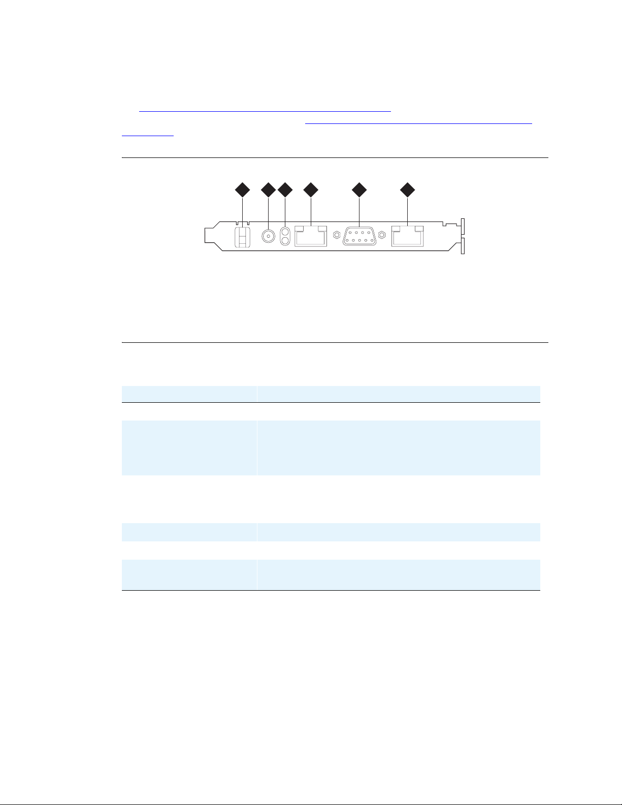
See Figure 1, Connector panel on the Remote Supervisor Adapter, on page 37 for locations of the
connectors and components of the RSA. See Table 3, Description of the Remote Supervisor Adapter
components, on page 37 for a detailed description of the components and connectors.
Figure 1: Connector panel on the Remote Supervisor Adapter
Installing the Avaya S8500 Media Server
1 2 3 4 5
Figure notes
1 Clip
2 External power-supply connector
3 Power and error LEDs
4 ASM RS-485 RJ14 connector
5 Serial connector
6 Ethernet RJ45 connector
6
h3msrsap LAO 071503
Table 3: Description of the Remote Supervisor Adapter components
RSA component Description
Clip Power cord retaining clip
External power-supply
connector
Connect the power-supply adapter to this conn ector. A power cord
connects from the power-supply adapter to the power source. This
connection provides power to the RSA that is independent of the
Avaya S8500 Media Server power supply.
Power and error LEDs The GREEN LED: Shows the status of the power connection.
The AMBER LED: Shows that an error condition exists on the
RSA.
Ethernet RJ-45 connector A 10/100 Mbps connector for LAN connectivity.
Serial connector Used for serial modem connectivity.
ASM RS-485 RJ-14
Not used in the Avaya S8500 Media Server configuration.
connector
December 2003
37
Page 38
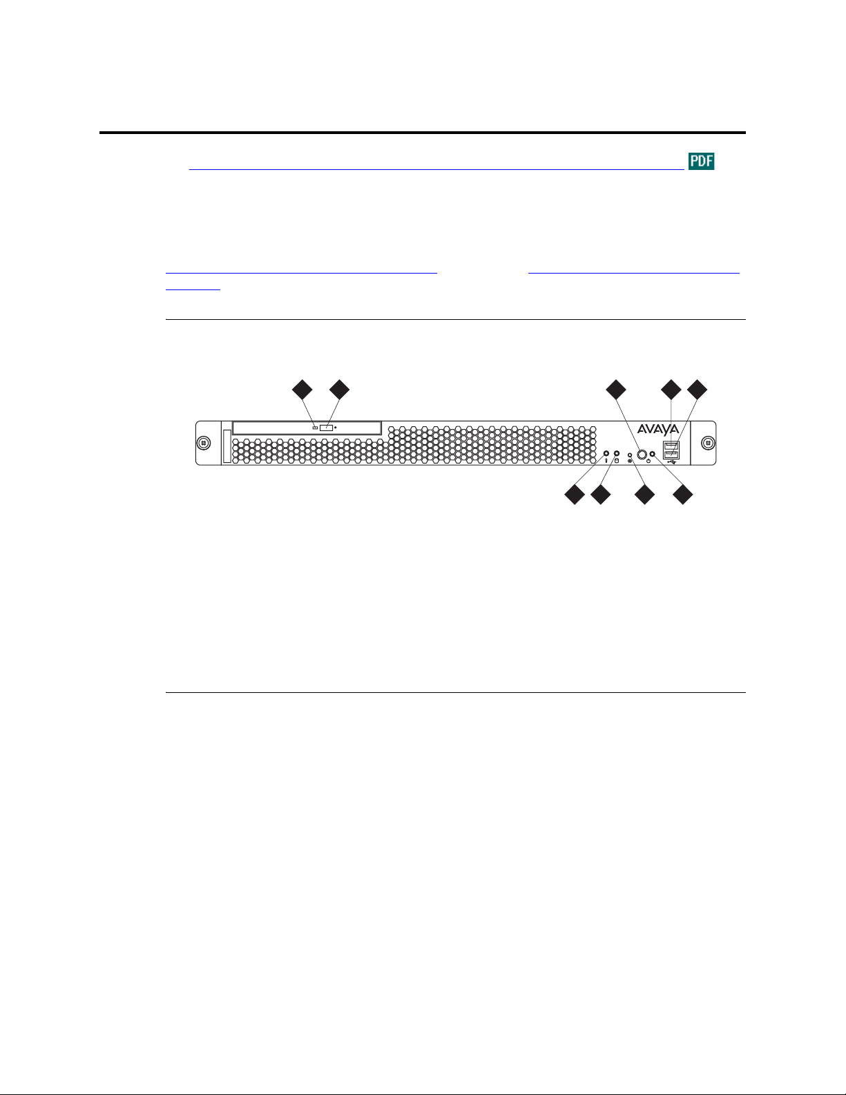
Mounting hardware in the rack
Mounting hardware in the rack
See Getting Started with the Avaya S8500 Media Server with the Avaya G650 Media Gateway for
information on mounting the hardware in the rack.
Avaya S8500 Media Server components
Figure 2, Avaya S8500 Media Server, front view, on page 38 and Figure 3, Avaya S8500 Media Server,
rear view, on page 39 show the location of the Avaya S8500 Media Server components.
Figure 2: Avaya S8500 Media Server, front view
2 4 5
1 3
disc
h3msfrnt LAO 070103
Figure notes
1 CD Activity LED
2 CD Eject button
3 On/Off switch
4 USB 2 port
5 USB 1 port
6
7
8 9
6 System error LED (amber)
7 Hard disk drive activity LED (green)
8 Reset button
9 Power on LED (green)
38 Installing the Avaya S8500 Media Server with an Avaya G650 Media Gateway
December 2003
Page 39
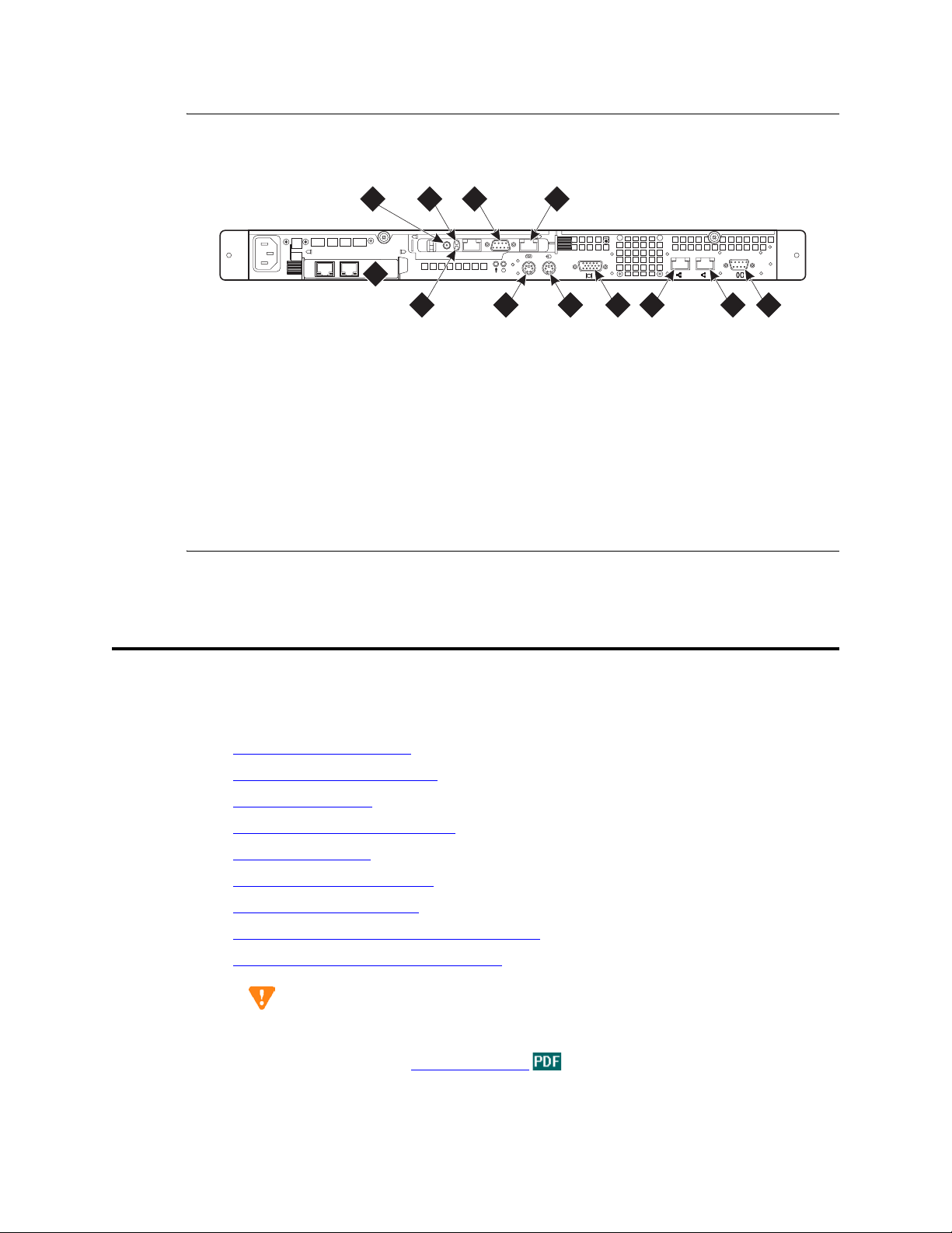
Figure 3: Avaya S8500 Media Server, rear view
Installing the network interface card
100-127 -, 3,0A, 50/60 Hz
200-240 -, 1,5A, 50/60 Hz
h3msble3 KLC 091603
Figure notes
1 Ethernet port
2 Power LED (green)
3 Error LED (amber)
4 External power
5 Serial modem to the RSA
6 Network interface card
1
12
PCI 2
PCI
1
133 MHz/64 Bit, 100 MHz/64 Bit
3
542
1011
7 Serial port
8 Services port
9 Ethernet port
10 Video port
11 Keyboard port
12 Mouse port
Installing the network interface card
LINK TX/RX LINK TX/RX
1 2
9
8 6
7
This section describes the steps required to install the optional network interface card (NIC) on the A vay a
S8500 Media Server. The control network traffic from the server out to the dedicated customer LAN
travels through the NIC. The components of this procedure include:
• Backing up the media server on page 40
• Powering down the media server on page 41
• Removing the fan unit on page 42
• Inserting the network interface card on page 43
• Replacing the fan unit on page 44
• Replacing the cover and cabling on page 44
• Powering up the media server on page 45
• Checking LED activity on network interface card on page 45
• Confirming original Ethernet configuration on page 46
CAUTION:
Wear an antistatic wrist ground strap whenever handling the media server or its
components. Connect the strap to an ap proved ground, su ch as an unpainted metal s urface.
See the job aid titled Approved Grounds
for more information.
Installing the Avaya S8500 Media Server with an Avaya G650 Media Gateway 39
December 2003
Page 40
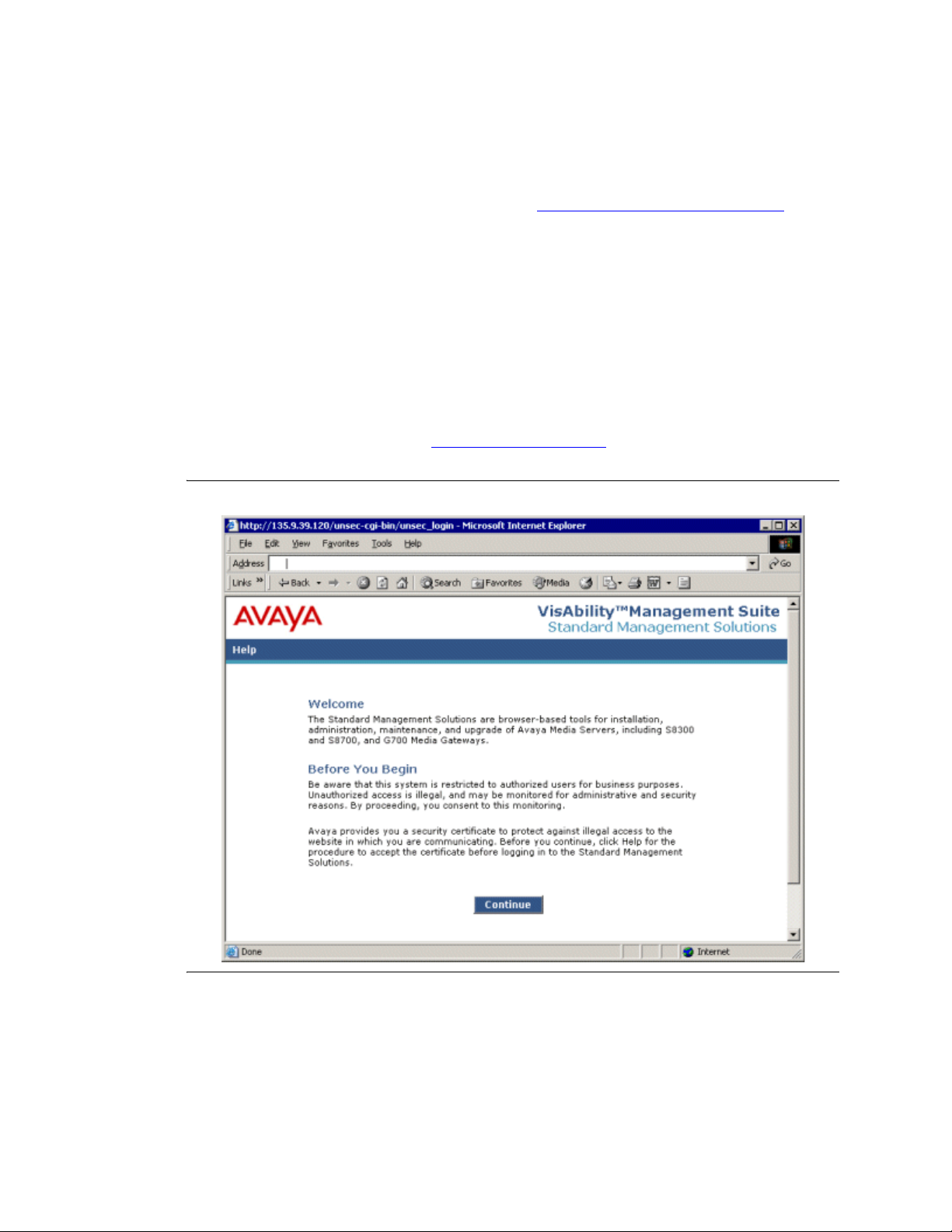
Installing the network interface card
Backing up the media server
NOTE:
If this is an installation being performed when the system is originally being set up, you do
not need to perform a backup. Proceed to Removing the cover of the medi a serv er
41.
If this is a new installation on a media server that has been in operation, perform a backup
first.
Backup the media server before you power it down. To backup the media server:
1 Connect the services laptop to the port labeled 2 (Eth 1) on the back of the media server us ing the
crossover cable.
2 Open a browser window on the laptop.
3 In the Address field of the browser, type the URL for the media server and press Enter.
on page
A welcome window opens (see Figure 4, Welcome window,
Figure 4: Welcome window
on page 40).
4 Click Continue.
5 Accept the Avaya certificate by clicking Yes.
6 Logon as craft or dadmin.
7 Suppress alarm origination by clicking Yes.
8 Click Launch Maintenance Web Interface.
40 Installing the Avaya S8500 Media Server with an Avaya G650 Media Gateway
December 2003
Page 41

9 In the navigation pane, click Backup Now.
10 Under the Data Sets heading, select all data sets.
11 Select one of the following backup methods:
• FTP
• E-mail
• Local PC card
12 If you want to encrypt the backup, select the Encrypt backup using pass phrase check box and
type a pass phrase.
13 Click Start Backup.
Powering down the media server
After the backup is finished, complete the following steps to power down the media server.
1 From the media server Web interface, click Shutdown This Server .
2 Select Delayed.
3 After the media server shuts down, unplug the power cord from the back of the server.
Installing the network interface card
4 Unplug the power cord from the Remote Supervisor Adapter (RSA).
5 Disconnect the modem from the RS-232 por t on the RSA.
6 Disconnect and label the LAN connection (if used) from the Ethernet port on the RSA.
7 Pull the server forward so that the server rails expand and the retaining clips on the rails click into
place.
8 Unplug and label the cable from the Ethernet port labeled LINK A on the dual NIC.
Removing the cover of the media server
CAUTION:
All power must be removed from the media server before starting this procedure.
1 Loosen the two captive screws on the back of the media server (see Figure 5, Locating the server
cover’s captive screws, on page 42.
2 Slide the server cover back from the front panel until the cover’s tabs are released from the top
slot of the front panel.
3 Lift the cover straight up and move it away from the server.
Installing the Avaya S8500 Media Server with an Avaya G650 Media Gateway 41
December 2003
Page 42
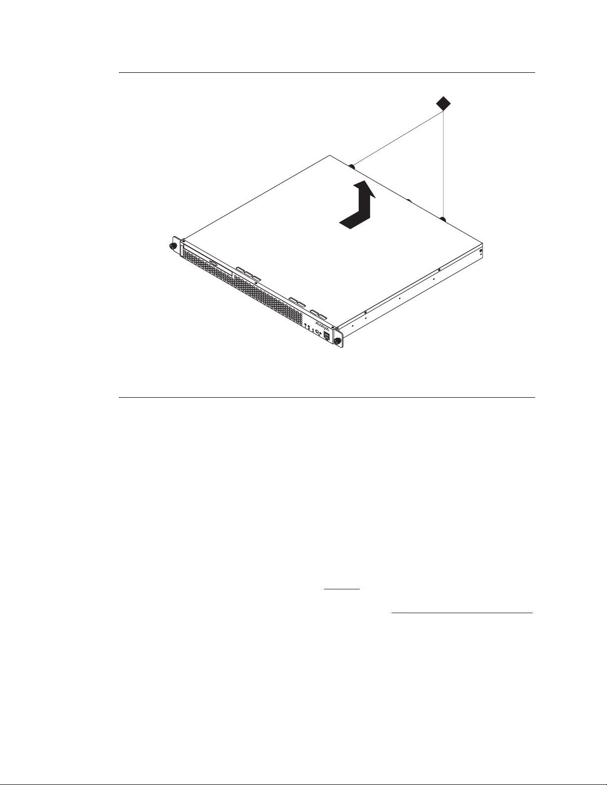
Installing the network interface card
Figure 5: Locating the server cover’s captive screws
disc
1
Figure notes
1 Server cover’s captive screws
Removing the fan unit
1 Locate the slot labeled PCI-2 on the left hand side of the back of the server under the fan unit.
2 Remove the two screws holding the fan unit. There is no need to unplug the fan unit.
3 Set the fan on the adapter-support bracket to the right.
Installing the small faceplate on the network interface card
One type of NIC comes from the factory with a standard faceplate. You must remove this faceplate and
replace it with a smaller one that fits the space. See Figure , ,
If you have a NIC that does not require a small faceplate, proceed to Inserting the network interface card
on page 43.
1 Using a #1 Phillips screwdriver, unscrew the two screws holding the larger faceplate.
2 Remove the faceplate from the NIC.
h3mscaps LAO 070103
on page 43.
3 Position the small faceplate over the Eth ernet por ts. The faceplate must align with the screw h oles
on the circuit board.
4 Screw the small faceplate onto the circuit board using the two screws removed in step 1.
42 Installing the Avaya S8500 Media Server with an Avaya G650 Media Gateway
December 2003
Page 43
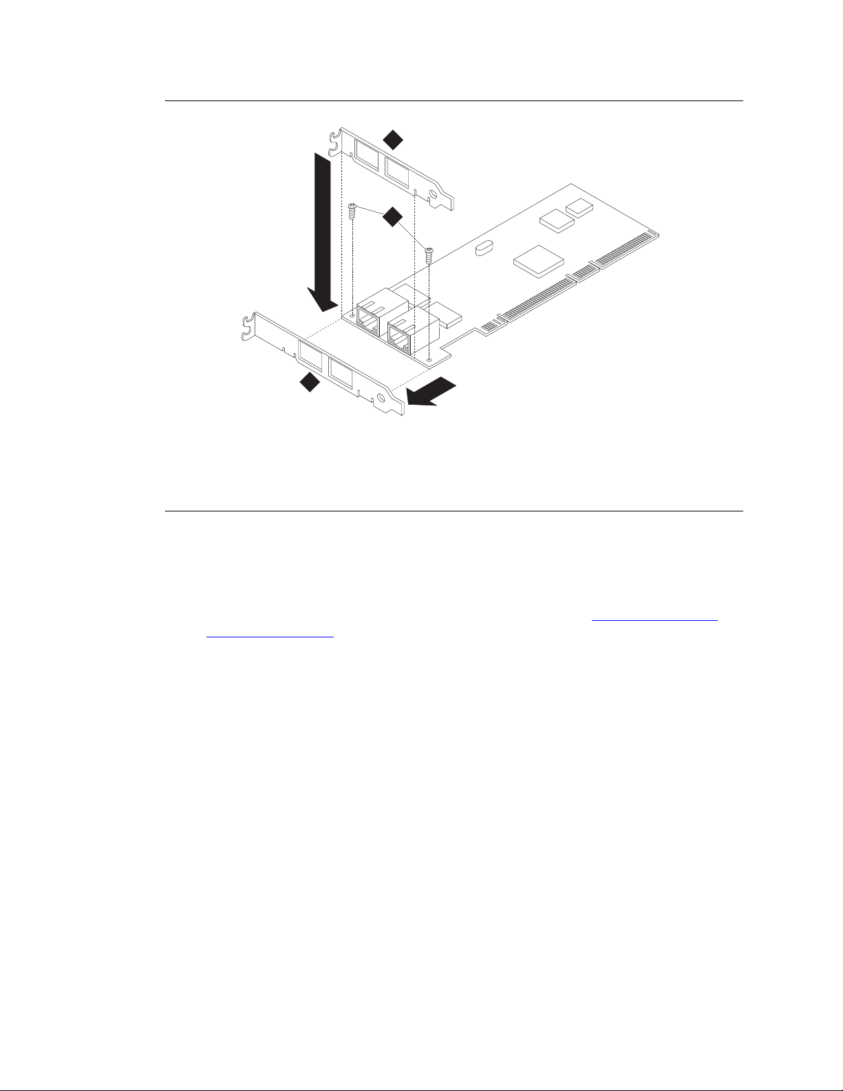
Figure 6: Replacing the faceplate
2
Figure notes
Installing the network interface card
3
1
h3msfnic LAO 072103
1 Screws holding faceplate
2 Faceplate on NIC shipped from
factory
Inserting the network interface card
1 Carefully grasp the new NIC card by the top edge or upper corners and align it with the PCI-2
expansion slot. Press the NIC card firmly into the expansion slot. See Figure 7, Inserting the
network interface card, on page 44.
3 Smaller faceplate
Installing the Avaya S8500 Media Server with an Avaya G650 Media Gateway 43
December 2003
Page 44
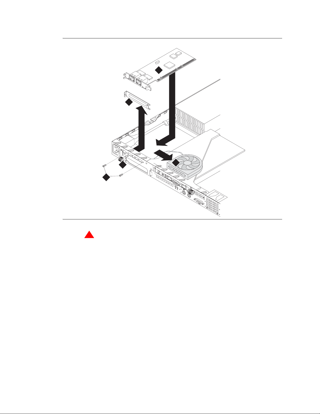
Installing the network interface card
Figure 7: Inserting the network interface card
5
4
1
0
0
-
1
2
2
0
7
0
-
-
2
,
4
3
0
,
0
-
A
,
1
,
,
5
5
0
A
/
6
,
0
5
0
H
/
6
z
0
H
3
P
z
C
I
1
P
C
I
2
2
1
!
WARNING:
Be sure that the NIC is completely and correctly seated in the PCI-2 expansion slot of the Avaya
S8500 Media Server. Incomplete insertion might cause damage to the system board or the NIC
2 Position the faceplate so that it fits in the PCI-2 slot using the captive screw to hold it in place.
3 Tighten the captive screw.
Replacing the fan unit
1 Replace the fan unit with the fan blades pointed down toward the NIC.
2 Secure the fan unit with the two original screws.
1
3
3
M
H
z
/6
4
B
it,
1
0
0
M
H
z
/6
4
B
it
.
Replacing the cover and cabling
1 Replace the cover onto the server.
2 Slide the cover forward so the covers’ tabs slide into place under the top slots of the front panel.
3 Finger-tighten the thumb screws on the back of the server.
44 Installing the Avaya S8500 Media Server with an Avaya G650 Media Gateway
December 2003
Page 45
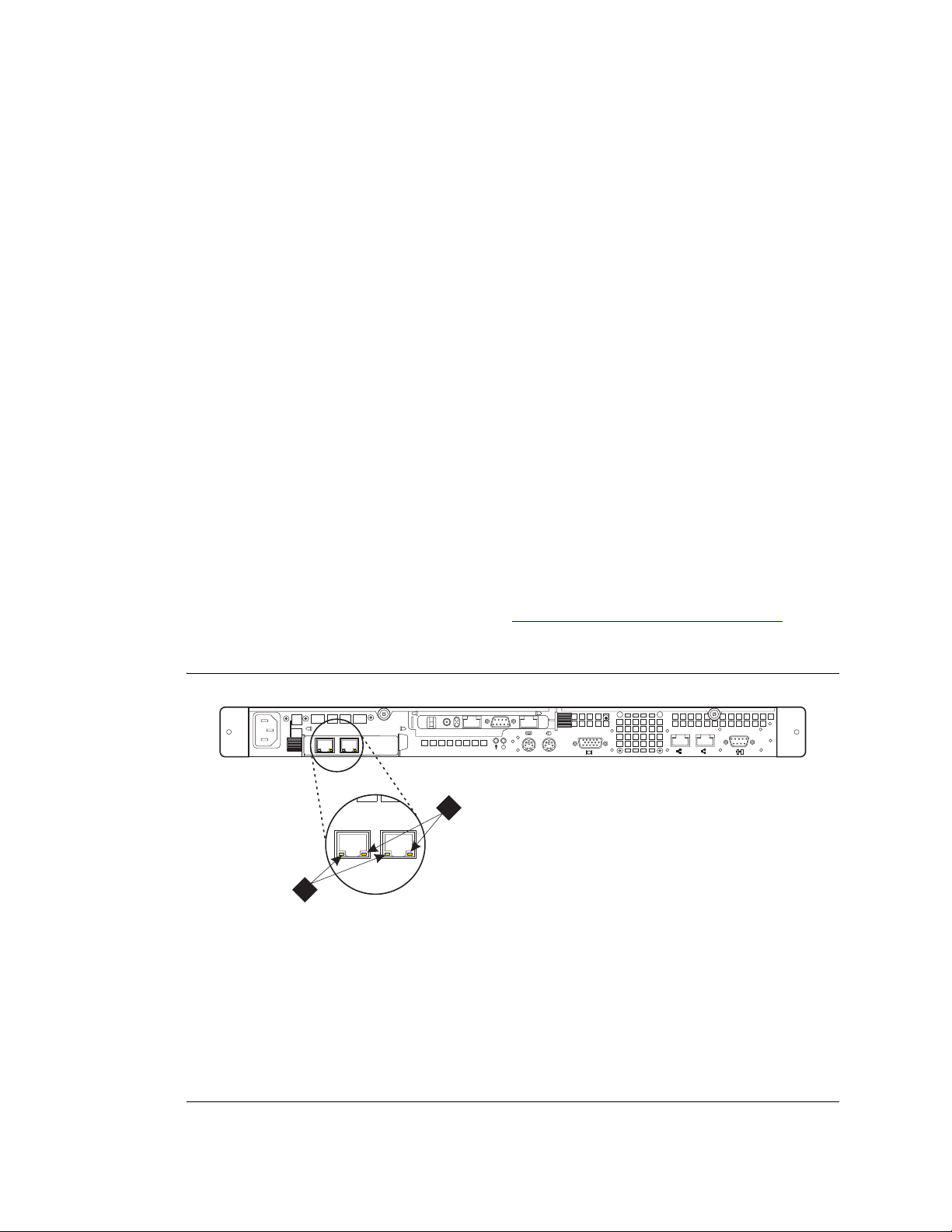
4 Release the retaining tabs on th e rails and s lide the Avaya S8500 Media Server back into place on
the data rack.
5 Locate the marked cable that you removed from the old NIC and plug it into the Ethernet 2 port,
which is labeled ACT/LINK A on the small faceplate of the new NIC.
6 Connect the modem to the RS-232 port on the RSA.
7 Plug the power cord to the Remote Supervisor Adapter (RSA).
Powering up the media server
To start the media server at this time:
1 Plug the power cord into the power receptacle on back of the server.
2 Press the power button located on the front right-hand side.
3 Log in to the server after the startup to make sure that the installation is complete.
Checking LED activity on network interface card
Installing the network interface card
NOTE:
This applies only if the optional dual-port NIC was installed.
When the media server is in service, check the LEDs on each port of the dual NIC card to make sure there
is a connection (left LED) and activity (right LED) (Figure 8, S8500 rear pa nel dual NIC LEDs,
on page
45
Figure 8: S8500 rear panel dual NIC LEDs
PCI
PCI 2
1
133 MHz/64 Bit, 100 MHz/64 Bit
LINK TX/RX LINK TX/RX
1 2
h3msble2 KLC 082503
2
1
100-127 -, 3,0A, 50/60 Hz
200-240 -, 1,5A, 50/60 Hz
100-127 -, 3,0A,
200-240 -, 1,5A, 5
Figure notes
1 Network activity LED (Tx/Rx) 2 Connection rate:
• LED is off: there is a 10 BASE-T
active link .
• LED is green: there is a 100 BASE-
T active link.
• LED is orange: there is a 1000
BASE-T active link.
Installing the Avaya S8500 Media Server with an Avaya G650 Media Gateway 45
December 2003
Page 46

Installing the network interface card
Confirming original Ethernet configuration
After the Media Server is back in service, check the original Ethernet configuration settings:
1 Go to the Configure Server Web page.
2 Confirm that the server’s Ethernet configuration settings are the same as before.
Configuring the NIC
1 Under Server, click Configure Server
2 Click Continue through the review notices until you get to the xxx page.
3 Select Configure Individual Services and click Continue.
4 Select Set Identities and click Continue.
5 The following Ethernet ports are listed:
• Control Network A: [default: Ethernet 0]
• Services Port: [default: Ethernet 1]
• Corporate LAN: [default: Ethernet 0]
• Unused
6 Using the dro p-down m enu, set the Corporate LAN field to Ether net 2 to have the IP SI control on
a dedicated, separate Ethernet port.
7 Click Continue.
8 Fill in the following information for Ethernet 2:
• IP address
• Gateway
• Subnet mask
• Speed
9 Select "VLAN 802.1q priority tagging is enabled" if true.
10 Click Change. The status of the configuration update appears in the window.
When the update completes, the following message appears:
ethernet interfaces
.
Successfully configured
46 Installing the Avaya S8500 Media Server with an Avaya G650 Media Gateway
December 2003
Page 47
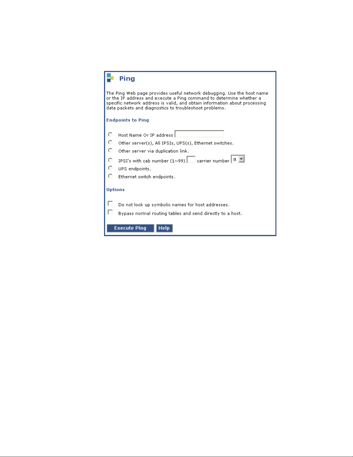
Testing connectivity to customer’s network
1 Under Diagnostics click Ping.
Installing the network interface card
2 In the Host Name or IP address field, type in the host name or IP address of a computer on the
network.
3 Click Execute Ping.
4 Verify that the ping was successful, indicating that the media server is connected to the cus tomer’s
network.
5 If DNS is administered, type in the host name of a computer on the network.
6 Click Execute Ping.
7 Verify that the ping was successful, indicating that DNS is working.
If available, have a customer representative do the following test from a computer on their network:
8 Click Start > Run to open the Run dialog box.
9 Type command and click OK to open an MS-DOS command window.
10 Type ping serveripaddress and click OK, where serveripaddress is the IP address of media
server.
11 Verify that the ping was successful.
12 If DNS is administered, type ping servername and press Enter, where servername is the host
name of media server.
13 Verify that the ping was successful.
Installing the Avaya S8500 Media Server with an Avaya G650 Media Gateway 47
December 2003
Page 48
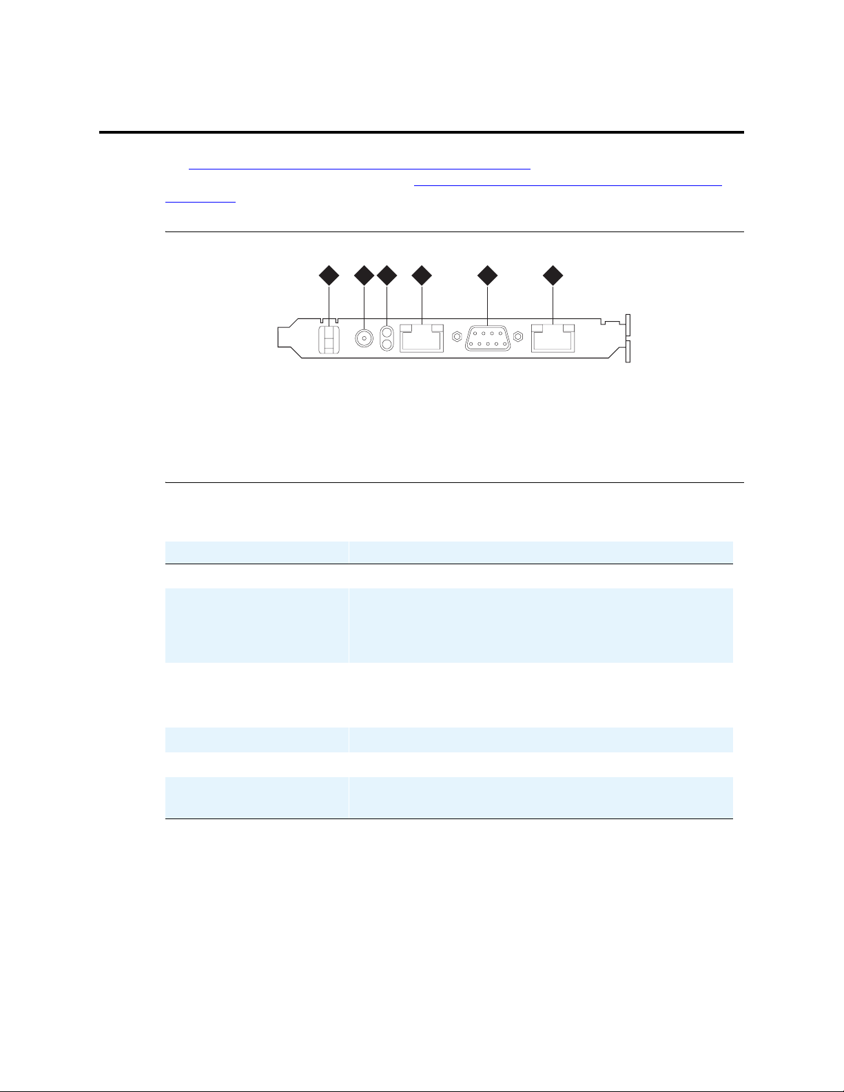
Remote Supervisor Adapter components
Remote Supervisor Adapter components
See Figure 9, Connector panel on the Remote Supervisor Adapter, on page 48 for locations of the
connectors and components of the RSA. See Table 4, Description of the Remote Supervisor Adapter
components, on page 48 for a detailed description of the components and connectors.
Figure 9: Connector panel on the Remote Supervisor Adapter
1 2 3 4 5
Figure notes
1 Clip
2 External power-supply connector
3 Power and error LEDs
4 ASM RS-485 RJ14 connector
5 Serial connector
6 Ethernet RJ45 connector
6
h3msrsap LAO 071503
Table 4: Description of the Remote Supervisor Adapter components
RSA component Description
Clip Power cord retaining clip
External power-supply
connector
Connect the power-supply adapter to this conn ector. A power cord
connects from the power-supply adapter to the power source. This
connection provides power to the RSA that is independent of the
Avaya S8500 Media Server power supply.
Power and error LEDs The GREEN LED: Shows the status of the power connection.
The AMBER LED: Shows that an error condition exists on the
RSA.
Ethernet RJ-45 connector A 10/100 Mbps connector for LAN connectivity.
Serial connector Used for serial modem connectivity.
ASM RS-485 RJ-14
Not used in the Avaya S8500 Media Server configuration.
connector
48 Installing the Avaya S8500 Media Server with an Avaya G650 Media Gateway
December 2003
Page 49

Connecting the modems
NOTE:
USB and serial modems cannot connect to rotary lines. A TouchTone line is required.
There are two modems on an Avaya S8500 Media Server configuration. One modem connects to the USB
port on the front of the Avaya S8500 Media Server. The other modem connects to the RS232 port on the
RSA card.
Required options on the USB modem is set by the operating system on the media server. Required
options on the RSA modem are set by Avaya defaults on the RSA board. There are no options to set on
either modem.
The modems for the media server and the RSA share one dedicated telephone line. The modem on the
Avaya S8500 Media Server always answers an incoming call if the media server is healthy. In the event
the media server is down, the modem on the RSA answers the incoming call. See Figure 10, Modem
connectivity on the Avaya S8500 Media Server, on page 50 for modem connectivity on the Avaya S8500
Media Server.
1 Terminate the 1-MB telephone line at the RJ11 jack outlet.
Connecting the modems
2 Connect the telephone line to the modems with the modular telephone cord supplied with each
modem.
3 Connect the USB cable from the USB modem to one of the USB ports on the front of the Avaya
S8500 Media Server.
4 Connect the serial cable from the serial modem to the RS232 port on the RSA card.
5 Connect the power cords from each modem to the power outlet.
Installing the Avaya S8500 Media Server with an Avaya G650 Media Gateway 49
December 2003
Page 50
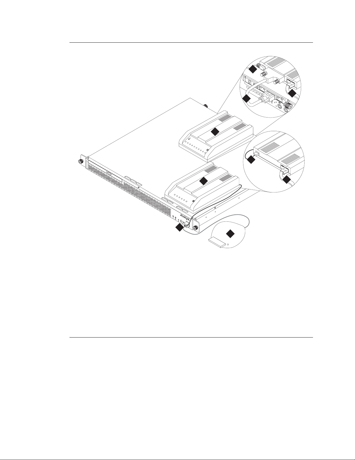
Connecting the modems
Figure 10: Modem connectivity on the Avaya S8500 Media Server
2
disc
Figure notes
133 MHz/64 Bit, 100 MHz/64 Bit
4
3
1
M
u
lti
M
o
d
e
m
M
u
lti
Te
S
o
c
ftw
h
a
re
6
5
M
u
lti
M
o
d
e
m
U
S
B
M
u
lti
Te
S
o
c
ftw
h
a
re
PWR
7
8
9
h3msmdsd LAO 072303
1 Serial modem used for the RSA.
2 Power cord for the modem.
3 Serial modem cable connecting the serial
modem to the RS-232 port on the RSA.
4 Telephone line connecting the serial
modem to the CO line.
5 USB modem used for Communication
Manager.
6 USB cable connecting the USB modem
to the USB port on the media server.
7 Telephone line connecting the USB
modem to the CO line.
8 2 USB ports on the front of the media
server.
9 Compact flash memory reader
connecting to the USB port on the media
server.
50 Installing the Avaya S8500 Media Server with an Avaya G650 Media Gateway
December 2003
Page 51

Configuring and connecting the hardware
Configuring and c onnecting the hardware
After you have installed the hardware in the rack (see the Getting Started Guide for the Avaya S8500
Media Server for installation information), you must install the Avaya Communication Manager CD,
configure the components, and connect them together.
This section covers the following tasks:
• Configuring the media server on page 52
• Configuring the SNMP modules in the uninterruptible power supplies on page 84
• Configuring the SNMP subagent in the Avaya Ethernet switch (if used) on page 87
• Configuring the network interface card on page 78
Installing the Avaya S8500 Media Server with an Avaya G650 Media Gateway 51
December 2003
Page 52

Configuring the media server
Configuring the me dia server
A new media server comes with a blank hard drive an d a bootable CD-ROM with Linux operating system
and Release 2.0 of Communication Manager on it.
Use the instructions in Getting Started with the Avaya S8500 Media Server with an Avaya G650 Media
Gateway to install the media server in the data rack. After installing the media server, you must install the
software from the CD onto the hard drive.
This section covers the following tasks:
• Copying files to the laptop on page 52
• Powering up the media server on page 53
• Accessing the media server on page 53
• Clearing the ARP cache on the laptop on page 53
• Setting up Telnet on page 53
• Installing the software on page 54
• Using the Installation Wizard on page 56
• Completing the Remote Supervisor Adapter configuration on page 58
• Checking LED activity on the network interface card on page 58
• Verifying media server connection to the customer’s LAN (if provided) on page 58
• Disconnecting from the media server on page 59
• Configuring the modem on page 80
NOTE:
Make sure you have the filled-out Electronic Preinstallation Worksheet (EPW) before
beginning this process.
NOTE:
Make sure your networking and Web browser settings are correct. See the job aid titled
Pre-Installation Information—Avaya S8500 Media Server
Copying files to the laptop
You must copy the required files to the laptop. This includes, but is not limited to, a software update
(patch), license file, Avaya authentication file, ART script, and filled-out Electronic Preinstallation
Worksheet (EPW).
You must copy all required RSA files listed on the EPW onto your laptop.
.
If you need to install a software update (patch), go to the Avaya Support Web site
(http://avaya.com/support
required software update.
To copy the license and Avaya authentication files, go to the RFA Web site (http://rfa.avaya.com
must have the serial number from the reference IPSI to get the new license file.
52 Installing the Avaya S8500 Media Server with an Avaya G650 Media Gateway
) and select Software & Firmware Downloads to identify and copy the
). You
December 2003
Page 53

Configuring the media server
Copy a blank EPW; go to the Avaya Installation Wizard Web site (http://support.avaya.com/avayaiw
Have the customer fill it out. Use the filled-out EPW provided by the project manager or customer.
NOTE:
The latest firmware for the programmable circuit packs and media modules may be on the
CD. Check the support website at http://avaya.com/support
Powering up the media server
1 Connect the AC power cord to the media server and to a nonswitched outlet or a UPS to power it
up. If it does not power up, press the white power control button on the front of the media server.
Accessing the media server
NOTE:
You must place the CD in the drive immediately.
1 Connect the laptop to the services port (port 2 [Eth1]) on the back of the media server using a
crossover cable.
2 Place the CD with Communication Manager in the CD-ROM drive on the media server.
3 Wait at least 3 minutes after powering up before starting a Telnet session to access the information
on the CD.
).
for the most current firmware.
Clearing the ARP cache on the laptop
NOTE:
Depending on your laptop computer’s operating system (generally Windows 2000), you
may need to clear the Address Resolution Protocol (ARP) cache before entering a new IP
address. If you enter an IP ad dress, and your co mputer cann ot connect, then yo u may ne ed
to clear the cache.
1 On your laptop computer, click Start > Run to open the Run dialog box.
2 Type command and press Enter to open a MS-DOS Command Line window.
3 Type arp -d 192.11.13.6 and press Enter to clear the Address Resolution Protocol (ARP) cache in
the laptop. This command will respond with one of the following:
• The command line prompt when the cache has been cleared.
• The phrase: The specified entry was not found. This is returned when the specified IP
address does not currently appear in the ARP cache.
Setting up Telnet
NOTE:
Use a telnet session to access the information on the CD.
Installing the Avaya S8500 Media Server with an Avaya G650 Media Gateway 53
December 2003
Page 54
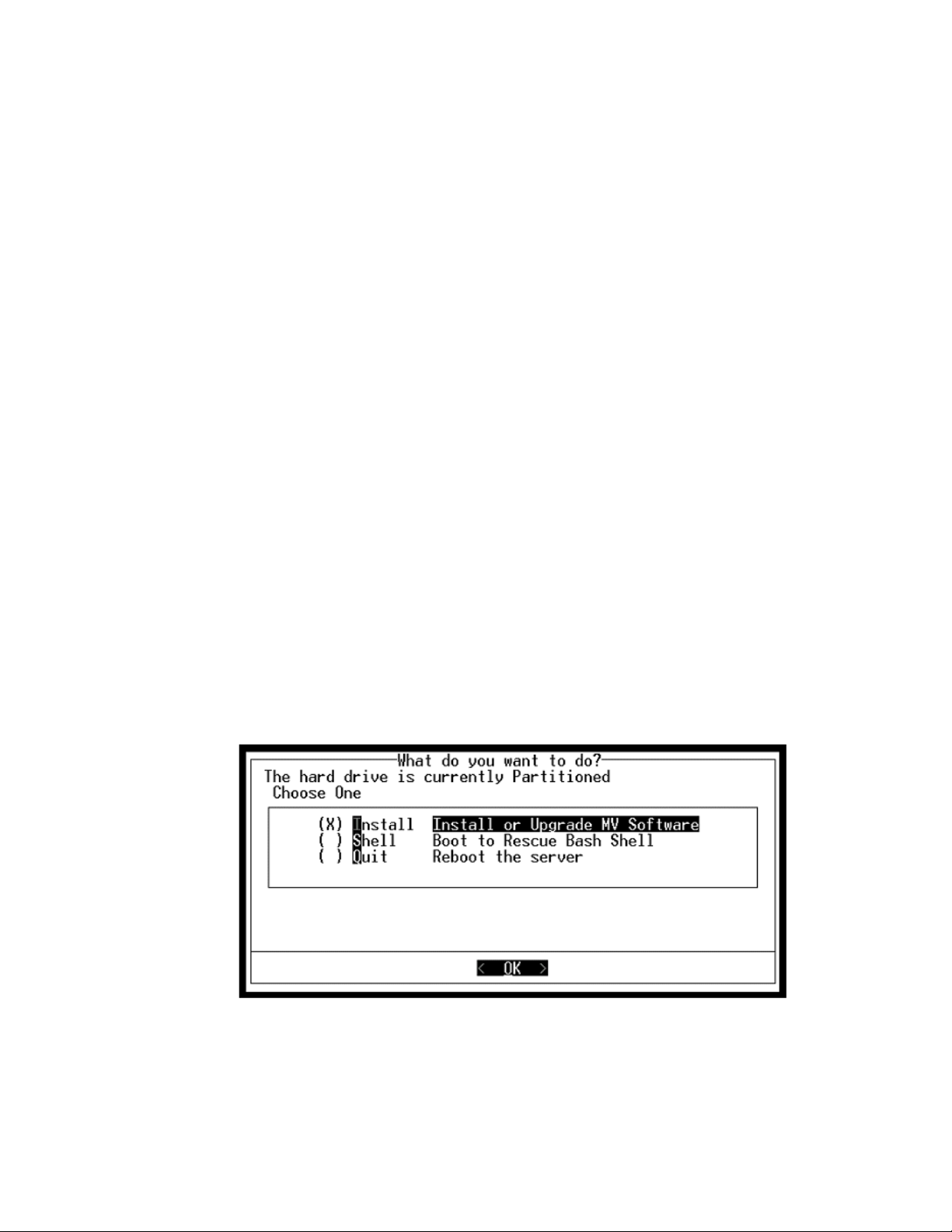
Configuring the media server
The Microsoft Telnet application may be set to send a carriage return (CR) and line feed (LF) each time
you press Enter. The installation program sees this as 2 key presses. You need to correct this before you
copy the RP to the hard drive.
1 Click Start > Run to open the Run dialog box.
2 Type telnet and press Enter to open a Microsoft Telnet session.
3 Type display and press Enter to see the current settings. If message says
Sending only CR
then close the dialog box.
If message says
Sending both CR & LF
then continue with step 4.
4 Type unset crlf and press Enter.
5 Type display and press Enter to verify that the settings changed. The message should say
Sending only CR
6 Close the dialog box.
Installing the software
NOTE:
Use a telnet session to access the information on the CD.
1 Type telnet 192.11.13.6 and press Enter to view the first screen.
NOTE:
T o navigate on these sc reens, use the arrow keys to mo ve to an option, then press the space
bar to select the option. Press Enter to su bmit th e screen.
54 Installing the Avaya S8500 Media Server with an Avaya G650 Media Gateway
December 2003
Page 55
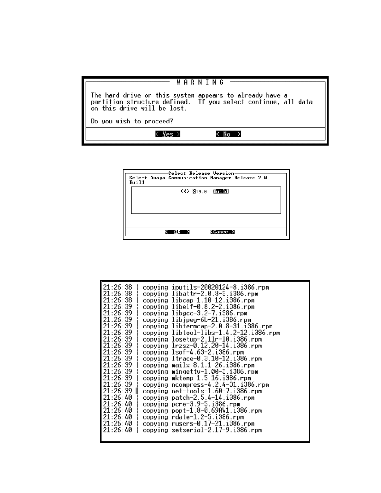
Configuring the media server
2 Select Install, make sure OK is highlighted, and press Enter.
The following screen is optional; it only shows if there is something on the hard driv e.
3 Select <Yes> and press Enter.
4 Select <OK> and press Enter to partition the hard drive and reformat the partitions
Once the drive is properly configured, the program begins the instal latio n pro cess and rep orts the
progress.
Installing the Avaya S8500 Media Server with an Avaya G650 Media Gateway 55
December 2003
Page 56
Configuring the media server
These processes can take up to 20 minutes. When the media server is ready to reboot, the CDROM drive drawer opens. You can remove the CD from the drive at this time.
The following screen flashes for about 5 seconds.
The reboot may take up to 3 minutes. The telnet session drops automatically.
Using the Installation Wizard
You can configure the media server and install the license, Avaya authentication files, and software
updates (patches) automatically using the Avaya Installation Wizard. You can do it two ways:
• You can import the data from the filled-out El ectronic Preinstallation Worksheet (EPW).
• You can also type in the information manually using the filled-out EPW as a guide.
To access the Installation Wizard:
1 Launch the Web browser.
2 In the Address field, type 192.11.13.6 and press Enter to bring up the login Web page.
NOTE:
The first time you attempt to log in, you get a Web page asking you to install a security
certificate. Follow the instructions for your particular browser to accept the certificate.
You can also install the certificate on your services laptop computer by following the
instructions in your browser’s online help.
3 Log in as craft and use the initial craft password.
4 When asked "Do you want to suppress alarms?", select "Yes."
NOTE:
On the initial Web page, some items may not appear at first. These include Launch Avaya
Station Administration Wizard in the Administration section and the Upgrade section
including Launch Upgrade Tool.
56 Installing the Avaya S8500 Media Server with an Avaya G650 Media Gateway
December 2003
Page 57
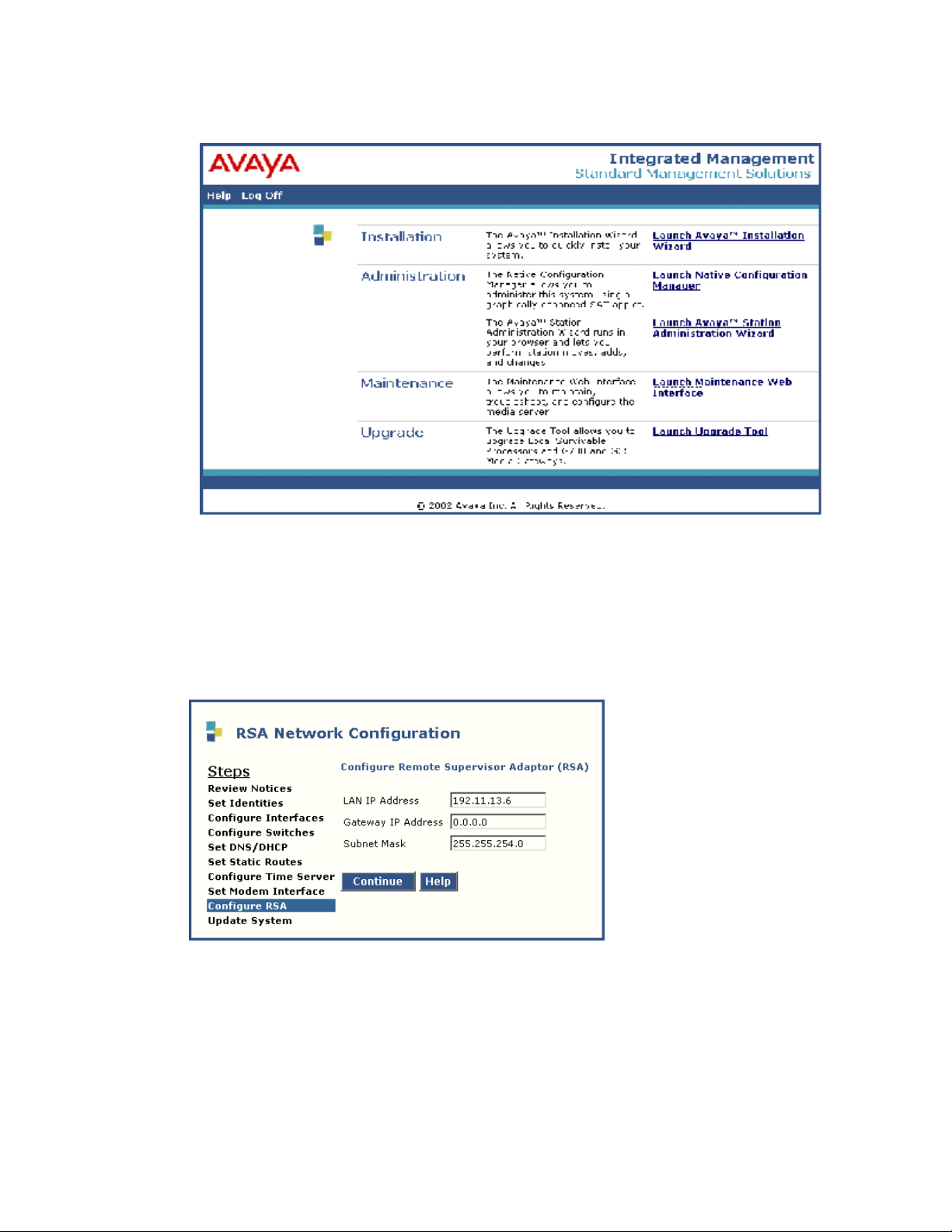
5 Click Launch Avaya Installation Wizard
.
Configuring the media server
6 Follow the prompts, using Help on each page for more information.
NOTE:
For the following step, if the RSA IP address is not configured correctly, the RSA web
pages
The Configure RSA page is the next to last page in the configuration process.
7 Verify the IP information for the RS A card h a s ret ri eved the da ta f rom the EPW. If the
information is not there, manually complete all fields.
• LAN IP Address field - 192.11.13.6
• Gateway IP Address field - 0.0.0.0
• Subnet Mask field - 255.255.254.0
The above information configures the RSA card for the cross-over cable.
Installing the Avaya S8500 Media Server with an Avaya G650 Media Gateway 57
December 2003
Page 58
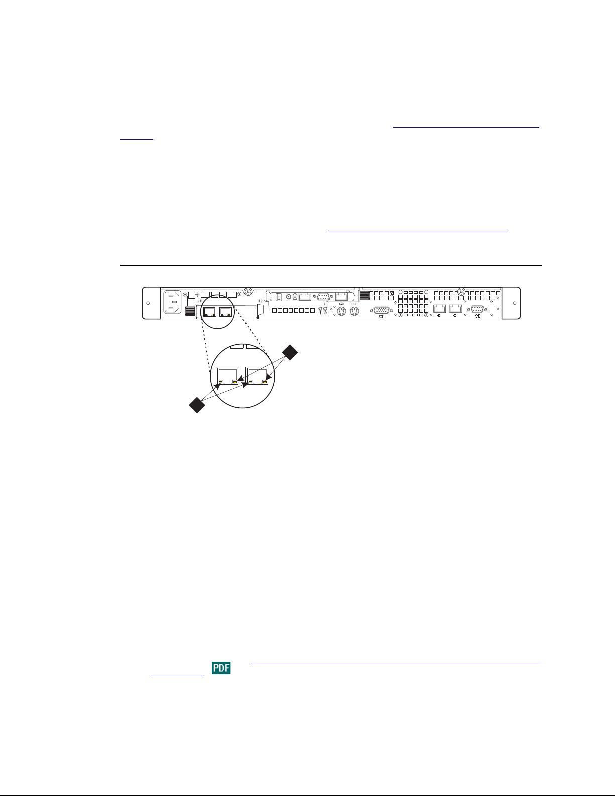
Configuring the media server
Completing the Remote Supervisor Adapter configuration
In order to successfully complete the configuration of the RSA, see Configuring the Remote Supervisor
Adapter on page 60.
Checking LED activity on the network interface card
When the media server is in service, check the LEDs on each port of the dual NIC card to make sure there
is a connection (left LED) and activity (right LED) (Figure 11, S8500 rear panel dual NIC LED s,
58
Figure 11: S8500 rear panel dual NIC LEDs
PCI
100-127 -, 3,0A, 50/60 Hz
200-240 -, 1,5A, 50/60 Hz
PCI 2
1
133 MHz/64 Bit, 100 MHz/64 Bit
on page
LINK TX/RX LINK TX/RX
1 2
h3msble2 KLC 082503
100-127 -, 3,0A,
200-240 -, 1,5A, 5
1
2
Figure notes
1 Network activity LED (Tx/Rx) 2 Connection rate:
• LED is off: there is a 10 BASE-T
active link .
• LED is green: there is a 100 BASE-
T active link.
• LED is orange: there is a 1000
BASE-T active link.
Verifying media server connection to the customer’s LAN (if provided)
1 Connect a customer-supplied CAT5 straight-through cable from the media server NIC, port 1
(Eth0) (or the option al du al-port NIC po rt 1 (Eth2) o r port 2 (Eth 3), if a ded icated networ k), to the
customer’s network. See Get ting Started wit h th e Avaya S8500 M edia Server with a n Avaya G650
Media Server.
58 Installing the Avaya S8500 Media Server with an Avaya G650 Media Gateway
December 2003
Page 59
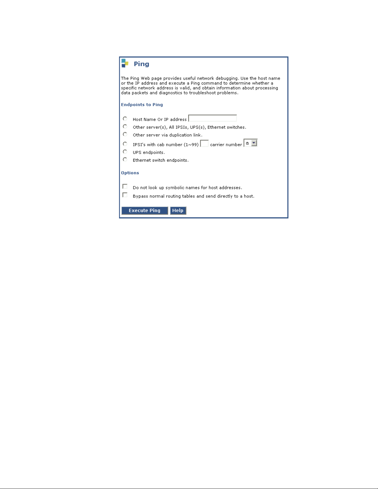
2 Under Diagnostics, click Execute Ping.
Configuring the media server
3 Type in the IP address of a computer on the network.
4 Click Execute Ping.
5 Verify that the ping was successful, indicating that the media server is connected to the cus tomer’s
network.
6 If DNS is administered, type in the host name of a computer on the network.
7 Click Execute Ping.
8 Verify that the ping was successful, indicating that DNS is working.
If available, have a customer representative do the following test from a computer on the network:
9 Click Start > Run to open the Run dialog box.
10 Type command and click OK to open an MS-DOS command window.
11 Type ping serverip add ress and click OK, where serveripaddress is the I P addr ess of the m edia
server.
12 Verify that the ping was successful.
13 If DNS is administered, type ping servername and press Enter, where servername is the host
name of the media server.
14 Verify that the ping was successful.
Disconnecting from the media server
• Unplug the crossover cable from the services port on the back of the media server.
Installing the Avaya S8500 Media Server with an Avaya G650 Media Gateway 59
December 2003
Page 60
Configuring the Remote Supervisor Adapter
Configuring the Remote Supervisor Adapter
This section describes the steps required to configure the Remote Su pervisor Adapter (RSA) on the
Avaya S8500 Media Server. The components of this procedure include:
• Connecting and logging in to the Remote Supervisor Adapter on page 62.
• Configuring the Remo te Su perv isor Adapter on page 63.
• Backing up the configuration on page 72.
• Restoring Advanced System Management configurations on page 74.
• Modifying a file on page 75.
• Setting auto answer on the RSA card.
• Updating RSA or BIOS firmware on page 76.
• Logging off the Remote Supervisor Adapter on page 77.
NOTE:
Before beginning the configuration process, see the prodpubs.avaya.com for any updates.
NOTE:
Make sure you have the filled out EPW before beginning the configuration process.
The RSA monitors and reports alerts on the A vaya S8500 Media Server components and pro vides contro l
to power-on and power-off the S8500. Usi ng a browser, the Advanced System Management (ASM) W eb
interface administers the RSA.
The RSA is installed in PCI-X slot 1 of the Avaya S8500 Media Server. Although all the software needed
to use the RSA comes installed from the factory, you still need to configure the RSA before you use it.
The RSA comes loaded from the factory with Avay a defaul ts. Not all fields could be set to a default.
NOTE:
Only the fields that need to be added or changed for an Avaya installation are outlined in
this section of the document. Fields that contain the Avaya defaults that do not need to be
modified can be found in Avaya RSA defaults
the RSA fields can be found in the Avaya Remote Supervisor Adapter User Guide
!
WARNING:
Executing the Restore Defaults option in the navigation pane removes the Avaya defaults. Avaya
defaults can be restored manually using t he info rmat i on fo und in Avaya RSA defaults
or by restoring the default file. The Avaya default file can be found at http://support.avaya.com
on the Communication Manager 2.0 CD for Linux Servers and Gateways. For instructions on
restoring the default file, see the Configuration File in the Avaya Remote Supervisor Adapter User
Guide.
on page 217. Detailed information on all
.
on page 217
or
60 Installing the Avaya S8500 Media Server with an Avaya G650 Media Gateway
December 2003
Page 61

Before you get started
Obtaining Avaya Registration Tool information
The Avaya Registration Tool (ART) is a Web-based program that permits Avaya employees to perform
product registrations and related procedures. Access the ART Web site (http://art.dr.avaya.com
need to obtain the following information from ART to complete and test the RSA configuration:
• The Avaya product ID. (Note: The RSA card uses the same ID as the server.)
• For modem alerting: Obtain the Avaya services telephone number that receives the alerts for your
region.
• For LAN alerting: Obtain the Avaya services IP address for the media server that will receive the
alerts for your region.
• For RSA access: Obtain an RSA password
Remote Supervisor Adapter power
NOTE:
We recommend that for RSA you use an external power source on a different circuit from
the Avaya S8500 Media Server.
Configuring the Remote Supervisor Adapter
). You
The RSA obtains power from an external power source or from the Avaya S8500 Media Server. For
external power, plug the cord from the power-supply adapter into the power connector on the RSA. The
power cord must be plugged from the power-supply adapter into the power source. A power LED on the
RSA lights when one or both of the following conditions are met:
• The RSA is receiving power from the external power-supply adapter.
• The RSA is receiving power from the Avaya S8500 Media Server in which it is installed.
LAN and serial port connectivity
Serial modem
The serial modem is used on the RSA to forward alerts to alert recipients and for remote access. For
information on how to connect the serial modem to the RSA, see Connecting the modems
LAN connectivity
To provide SNMP alerting over LAN connectivity, connect a customer-provided CAT5 cable to the
Ethernet port on the RSA card.
.
Installing the Avaya S8500 Media Server with an Avaya G650 Media Gateway 61
December 2003
Page 62
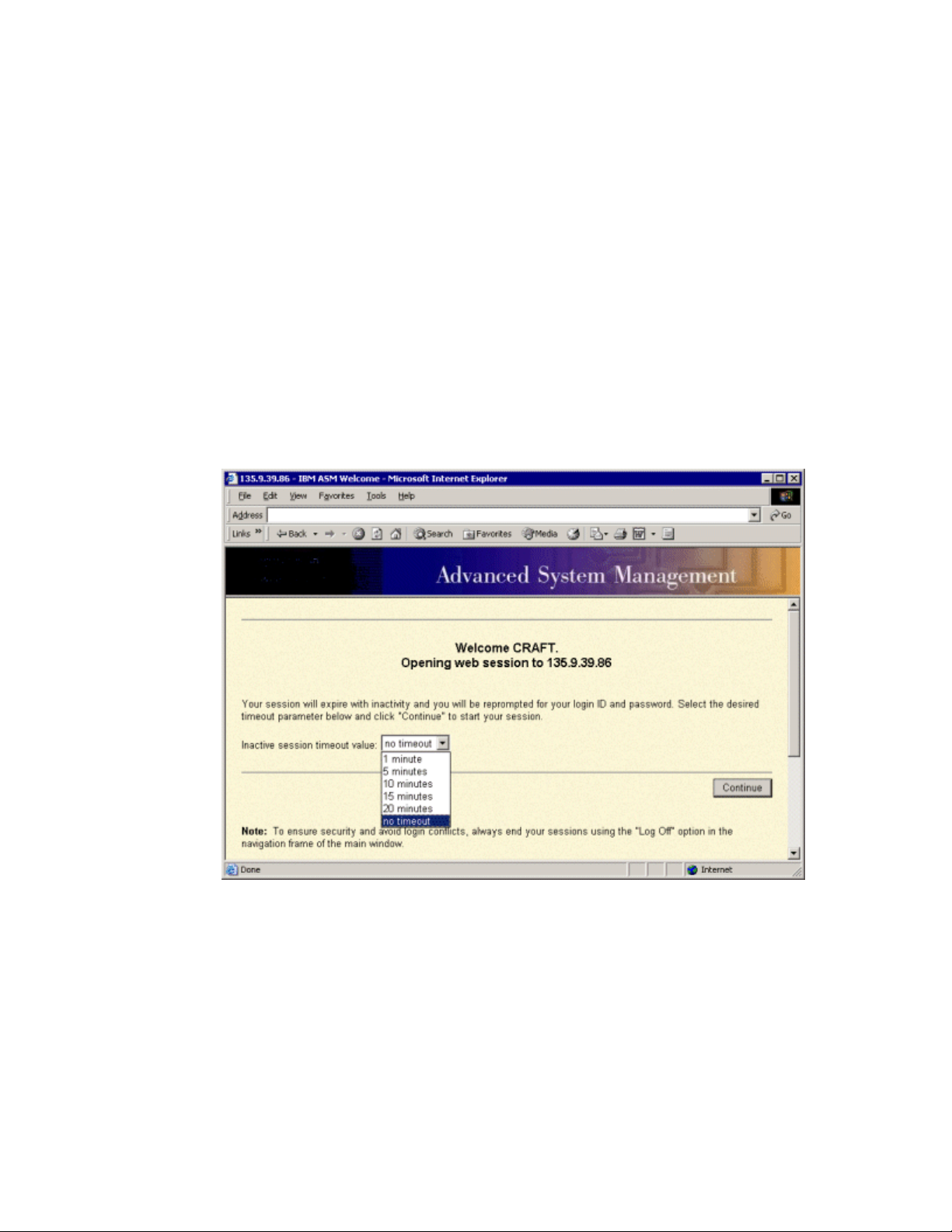
Configuring the Remote Supervisor Adapter
Connecting and logging in to the Remote Supervisor Adapter
NOTE:
At the completion of some of the following steps you will be prompted to restart ASM. Do
not restart ASM at this time. You will be reminded to restart the ASM once all the
configuration steps are completed.
Use the following steps to connect and log in to the RSA:
1 Connect the services laptop to the Ethernet port on the RSA using a crossover cable.
2 Open a browser.
3 In the Address field, type 192.11.13.6 and press Enter.
The system displays the Enter Network Password window.
Log on as craft, using password passw0rd (with a zero).The system displays the Welcome
window.
4 From the Inactive session time value field, click no timeout, which allows 60 minutes of use
before disconnecting.
NOTE:
If the session times out unexpectedly, click Start New Session and Refresh.
5 Click Continue.
62 Installing the Avaya S8500 Media Server with an Avaya G650 Media Gateway
December 2003
Page 63
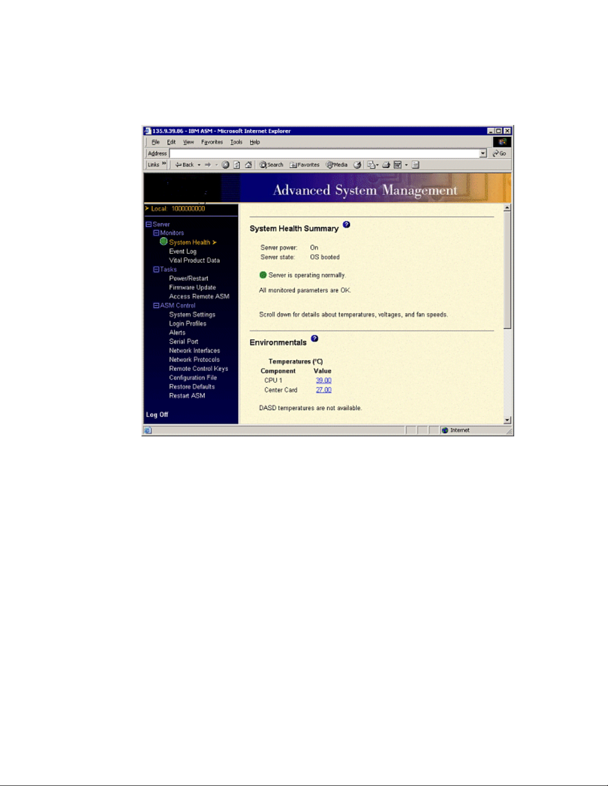
Configuring the Remote Supervisor Adapter
The Advanced System Management Web page is divided into a left navigation pane and a display pane.
Configuring the Remote Supervisor Adapter
For security reasons, you must change the default login ID and password when you first log on.
Installing the Avaya S8500 Media Server with an Avaya G650 Media Gateway 63
December 2003
Page 64
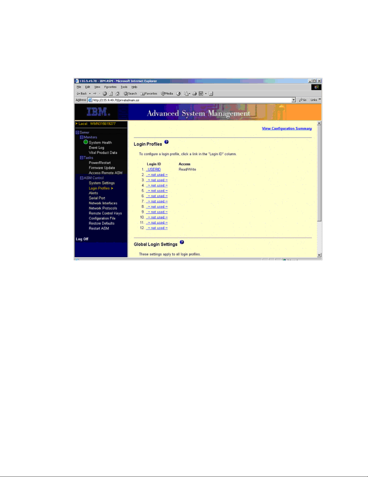
Configuring the Remote Supervisor Adapter
Changing login ID and password
1 Under ASM Control, click Login Profiles.
The system displays the Login Profiles window.
64 Installing the Avaya S8500 Media Server with an Avaya G650 Media Gateway
December 2003
Page 65
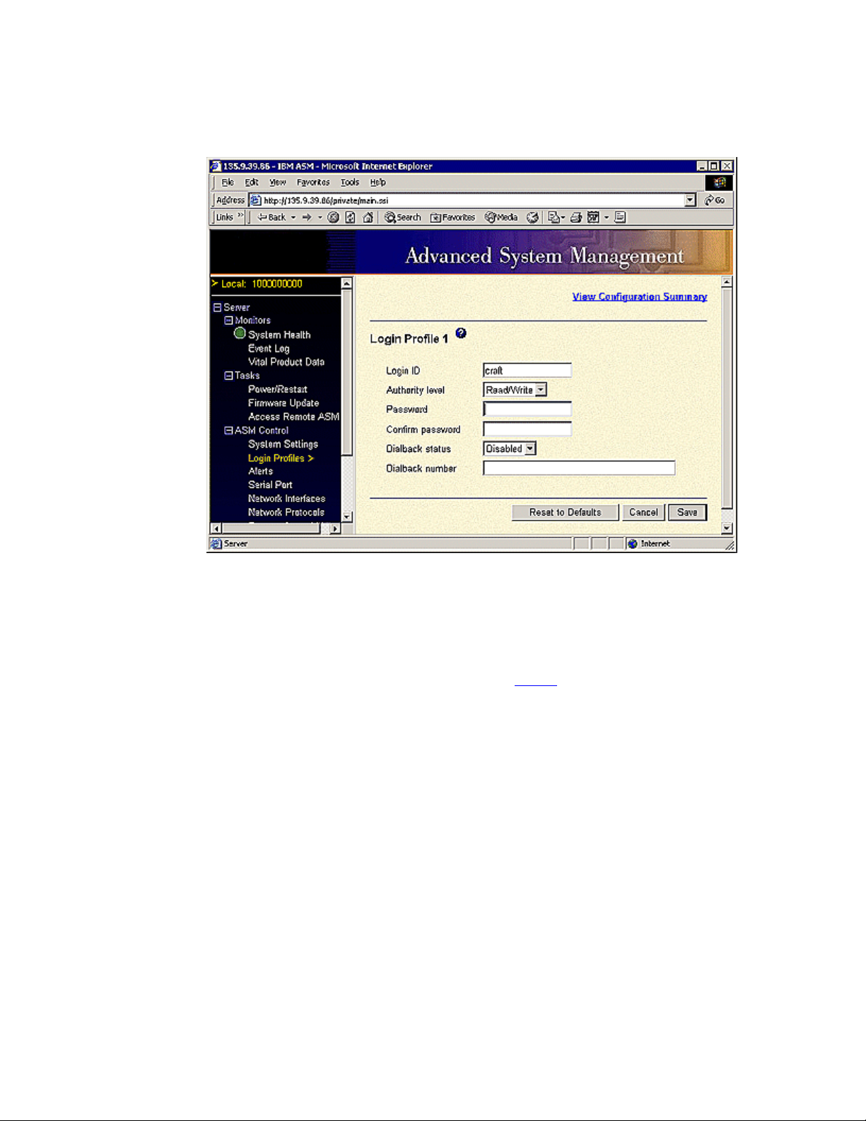
2 Under the Login ID column, click craft.
The system displays a login profile window.
Configuring the Remote Supervisor Adapter
3 In the Authority level field, select Read/Write.
4 In the Password field, type in the new password from ART.
5 In the Confirm Password field, type the new password again.
6 Click Save.
7 If you are a business partner and need your own login, click on item 2 on the Login Profiles
window. If you are not a business partner, proceed to Step 13
The system displays a login profile window.
.
8 In the Login ID field, type an ID (preferably dadmin).
9 In the Authority level field, select Read/Write.
10 In the Password field, type in the new password from ART.
11 In the Confirm Password field, type the new password again.
12 Click Save.
13 On the Login Profiles window, scroll down to the bottom and click Save.
Installing the Avaya S8500 Media Server with an Avaya G650 Media Gateway 65
December 2003
Page 66
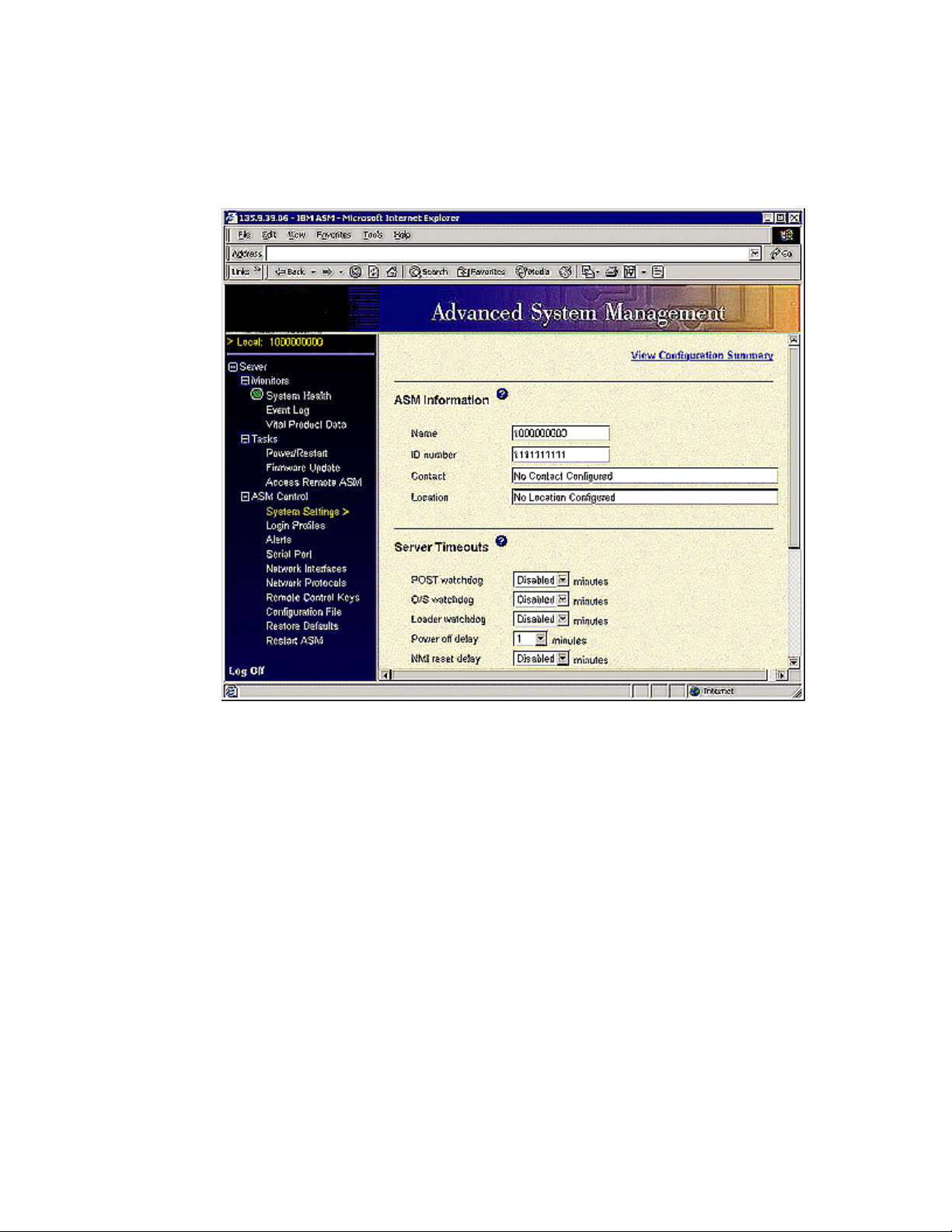
Configuring the Remote Supervisor Adapter
Configuring Advanced System Management
1 Under ASM Control, click System Settings.
The system displays the System Setting window.
2 In the Name field, type in the Avaya product ID number from ART.
The ID number is set to the Avaya default. A new ID number can be entered in the
field if needed.
ID number
3 In the Contact field, type in the contact information.
4 In the Location field, type in the location information.
66 Installing the Avaya S8500 Media Server with an Avaya G650 Media Gateway
December 2003
Page 67
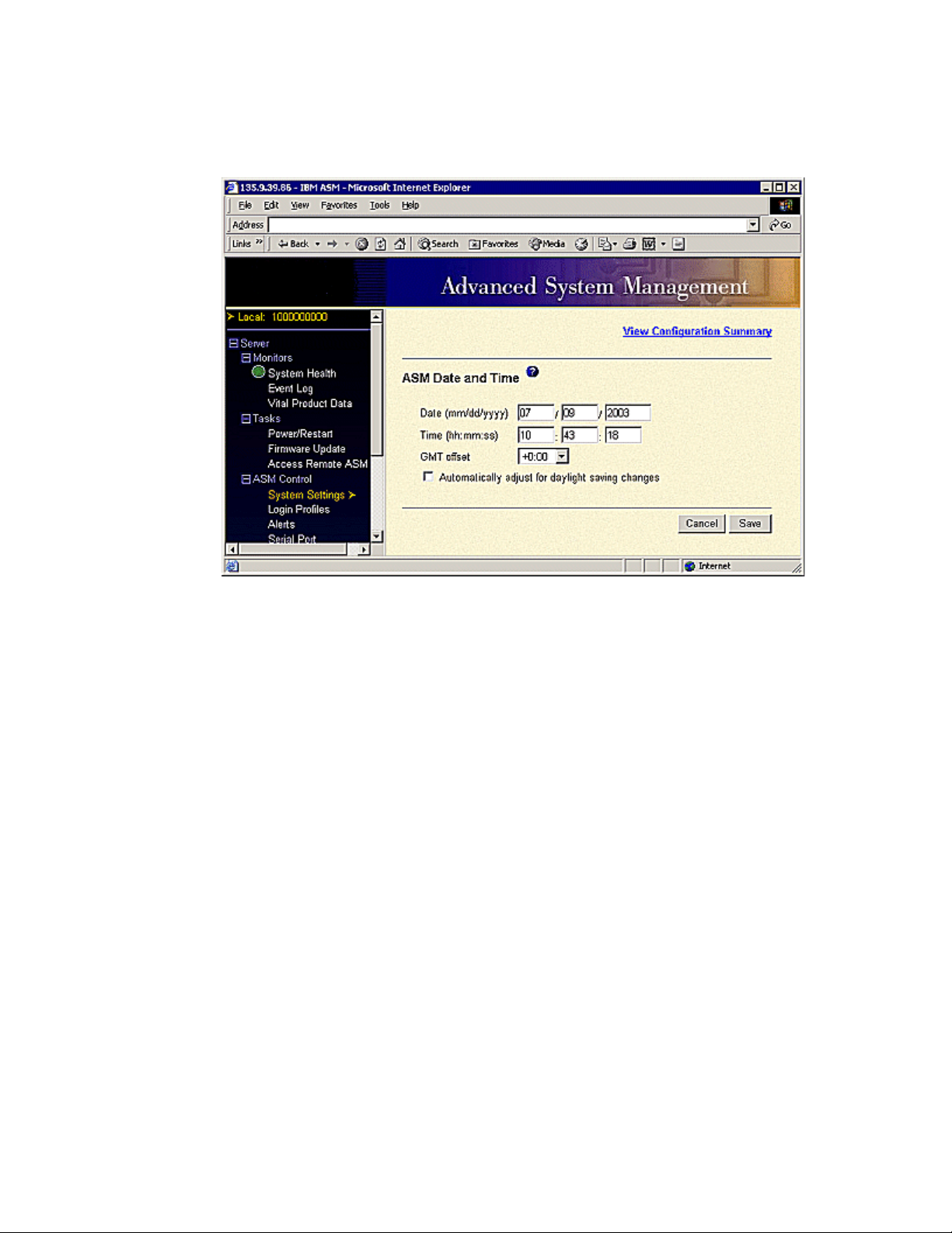
Configuring the Remote Supervisor Adapter
5 Scroll down to the section titled ASM Date and Time and click Set ASM Date and Time.
The system displays the ASM Date and Time window.
6 Type in the current date and time in the correct fields.
7 In the GMT offset field, use the drop-down menu to select the Greenwich Mean Time offset for
your region. For example, Denver, Colorado, would be - 7:00 for MST.
8 Select Automatically adjust for daylight savings time changes if daylight savings is used in
your area.
9 Click Save.
10 Scroll down to the bottom of the System Settings window and click Save.
Installing the Avaya S8500 Media Server with an Avaya G650 Media Gateway 67
December 2003
Page 68
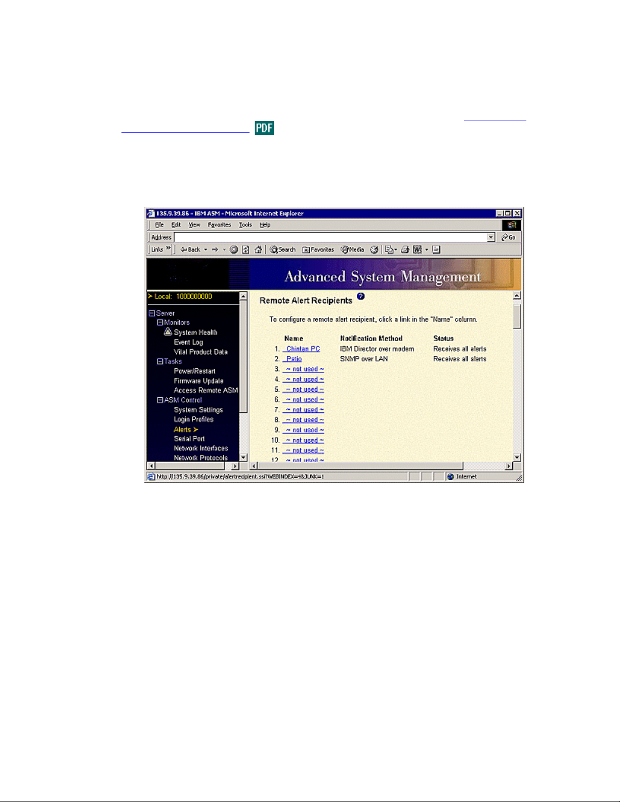
Configuring the Remote Supervisor Adapter
Setting alarms
Although the configuration for the remot e alarming is done in one section , you need to see other panes to
complete the configuration before you test it. For more detailed information, see the Avaya Remote
Supervisor Adapter User Guide.
Complete the following steps to enter Avaya as an alarm recipient for this location.
1 Under ASM Control, click Alerts.
The system displays the Remote Alert Recipients window.
68 Installing the Avaya S8500 Media Server with an Avaya G650 Media Gateway
December 2003
Page 69
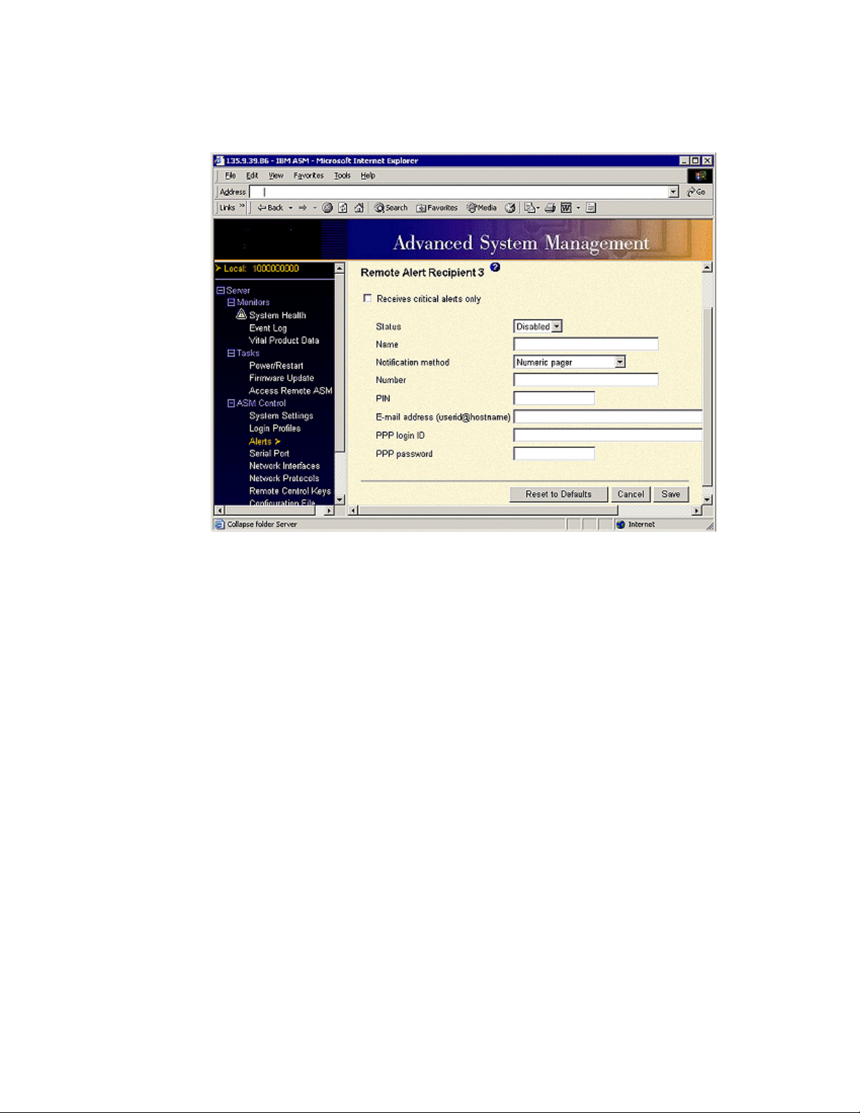
Configuring the Remote Supervisor Adapter
2 Under the Name column, click on the first nonconfigured line (~not used~).
The system displays a new window with the following with the following configuration fields.
NOTE:
Do not select the Receives Critical Alerts Only check box.
3 Fill in the following fields:
• Status: Select Enabled from the drop-down menu.
• Name: Type in a name representing Avaya services.
• Notification method: Select one of the following from the drop-down menu:
— To send alerts to INADS over modem, select IBM Director over Modem.
— To send alerts to INADS over SNMP, select SNMP over LAN.
• Number:
— If you select IBM Director over Modem, type in 9,18005353573 (if a direct line,
you do not need the 9,).
— If you select SNMP over LAN, type in the Avaya IP address or Avaya hostname
that will receive the SNMP alerts. Additional administration must be completed in
the Network Protocols section before SNMP over LAN is used.
4 Click Save.
This is the only part you must fill out in the Alerts section. Keep the remaining fields as Avaya default
settings.
NOTE:
Testing the alert recipient cannot be done at this time. Please wait until all configuration
steps are completed to test the alert recipients
Installing the Avaya S8500 Media Server with an Avaya G650 Media Gateway 69
December 2003
Page 70
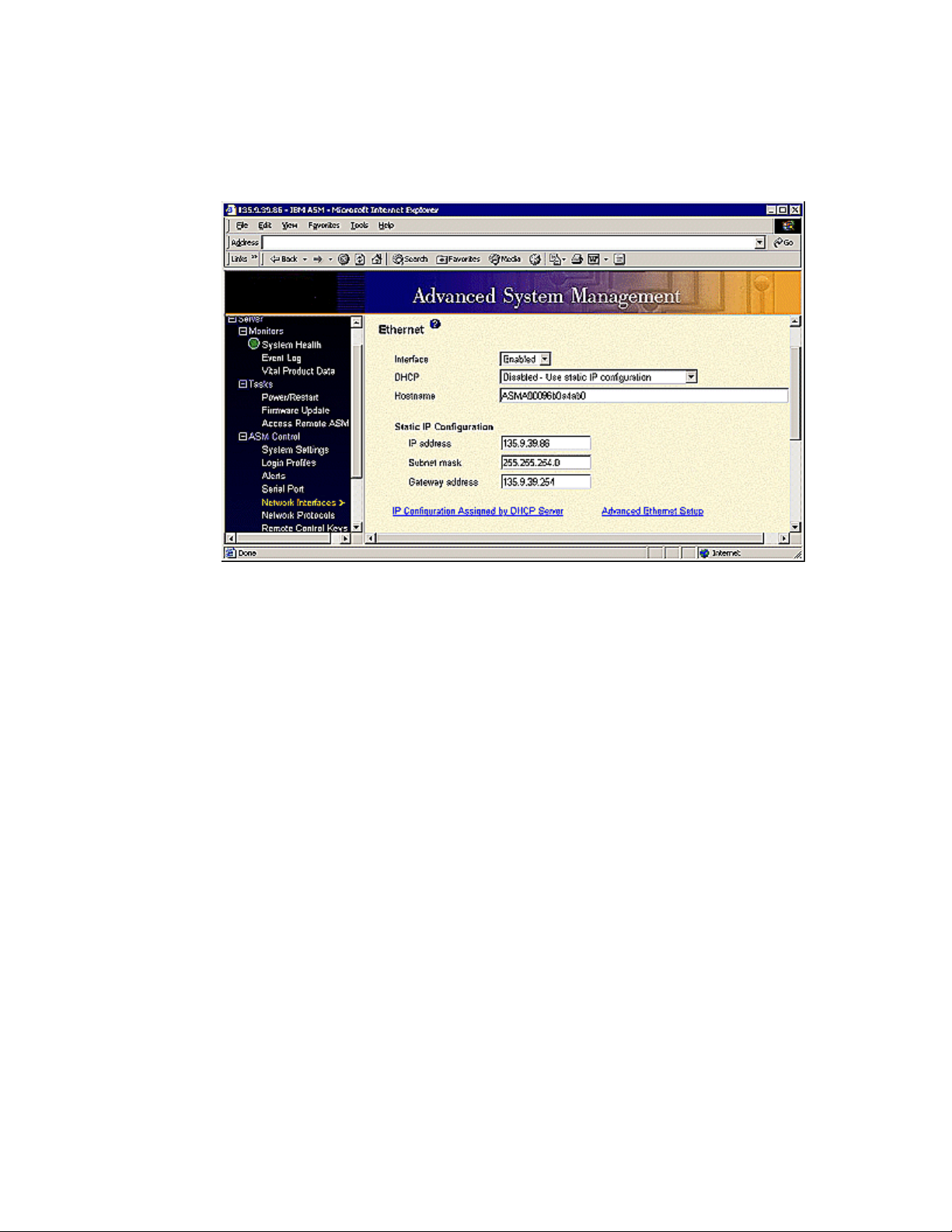
Configuring the Remote Supervisor Adapter
Configuring network interfaces
1 Under ASM Control, click Network Interfaces.
The system displays the Ethernet window.
.
NOTE:
The Ethernet Interface is set to Enabled via the Avaya defaults. The Static IP Address,
Gateway address, and Subnet Mask fields are set using the Maintenance Web Interface
when you configure the Ethernet ports on the Avaya S8500 Media Server.
2 In the DHCP field, select Disabled - Use static IP configuration.
3 If you are not using DHCP, then under the Static IP Configuration heading, verify that the Static
IP address
If you are using DHCP, continue to the next step.
, Subnet mask, and Gateway address fields are correct.
4 In the Hostname field, type in the IP hostname of the RSA.
5 Scroll down to the bottom of the window and click Save.
To see the IP configuration settings, click IP Configuration Assigned by DHCP Server.
70 Installing the Avaya S8500 Media Server with an Avaya G650 Media Gateway
December 2003
Page 71
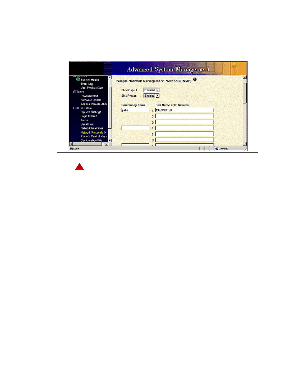
Configuring network protocols
1 Under ASM Control, click Network Protocols.
The system displays the Simple Network Management Protocol (SNMP) window.
Configuring the Remote Supervisor Adapter
!
DANGER:
Perform the following steps to configure SNMP and DNS:
For SNMP:
a Enable the SNMP agent and SNMP traps.
b Type in Avaya Services for the community name
c Type in the IP address for the server receiving the alarms.
d Scroll down and click Save. Delay clickin g Save if a DNS server is used.
For DNS:
a In the DNS field, select Enable DNS from the drop-down menu.
b In the DNS server IP address 1 field, type in the IP address for DNS server 1.
c In the DNS server IP address 2 field, type in the IP address for DNS server 2 (if used).
d In the DNS server IP address 3 field, type in the IP address for DNS server 3 (if used).
e In the Hostname field, complete the IP-address-to-hostname mappings by filling out the
IP address field.
f Scroll down and click Save.
2 Under ASM Control, click Restart ASM to reboot.
Installing the Avaya S8500 Media Server with an Avaya G650 Media Gateway 71
December 2003
Page 72
Configuring the Remote Supervisor Adapter
Backing up the configuration
Once the configuration is complete, you must backup the RSA administration changes. A copy of the
ASM backup can be stored on the laptop computer (in case something happened to the RSA card, the
settings could be restor ed easily) o r you may select another serv er on the cust omer’ s network. If t he latter,
you must have a log in I D and p assw ord. You can use the backup cop y t o restor e th e RSA config uration in
the event of damage or corrupti on. You also can modify the saved configura tio n file b efore res torin g it on
the RSA.
Complete the following steps to backup the ASM configuration:
1 Click Configuration File.
2 In the Backup ASM Configuration section, click View the current configuration summary.
3 Verify that these are the settings that you want to save, then click Close.
If the settings are not as desired, go to the respective areas and update the information. See Table
5, Updating the configuration summary, on page 72. To review system defaults, see ‘‘Avaya RSA
defaults’’ on page -217.
Table 5: Updating the configuration summary
Configuration summary item Where to update information
ASM Information System Settings
Server Timeouts System Settings
ASM Date and Time System Setting
Scheduled Power On Power/Restart > Server Power / Restart Control > Power on at
Specified Time
Remote Control Keys Remote Control Keys
Login Profiles Login Profiles
Global Login Settings Login Profile
Remote Alert Recipients Alerts
Alert Forwarding Alerts
Global Remote Alert Settings Alerts
Monitored Alerts Alerts
Monitored Local Events Alerts
Serial Port Serial Port
Modem Settings Serial Port > Advanced Modem Settings
Ethernet Network Interfaces
Advanced Ether Setup Network Interfaces > Advanced Ethernet Setup
PPP over Serial Port Network Interfaces
SNMP Network Protocols
72 Installing the Avaya S8500 Media Server with an Avaya G650 Media Gateway
December 2003
Page 73
Configuring the Remote Supervisor Adapter
Table 5: Updating the configuration summary
Configuration summary item Where to update information
DNS Network Protocols
SMTP Network Protocols
4 In the Backup ASM Configuration section, click Backup.
5 Type in a name for the backup file and choose a location where the backup file is to be stored.
NOTE:
If you are LAN connected, you can back up the configuration file to any server on the
LAN. If you are accessing the RSA directly through the RSA Ethernet port, you are able
to backup the configuration to the services laptop.
6 Select
• Save this file to disk and then OK if MS Internet Explorer.
• Save File, then OK if Netscape Navigator
Installing the Avaya S8500 Media Server with an Avaya G650 Media Gateway 73
December 2003
Page 74
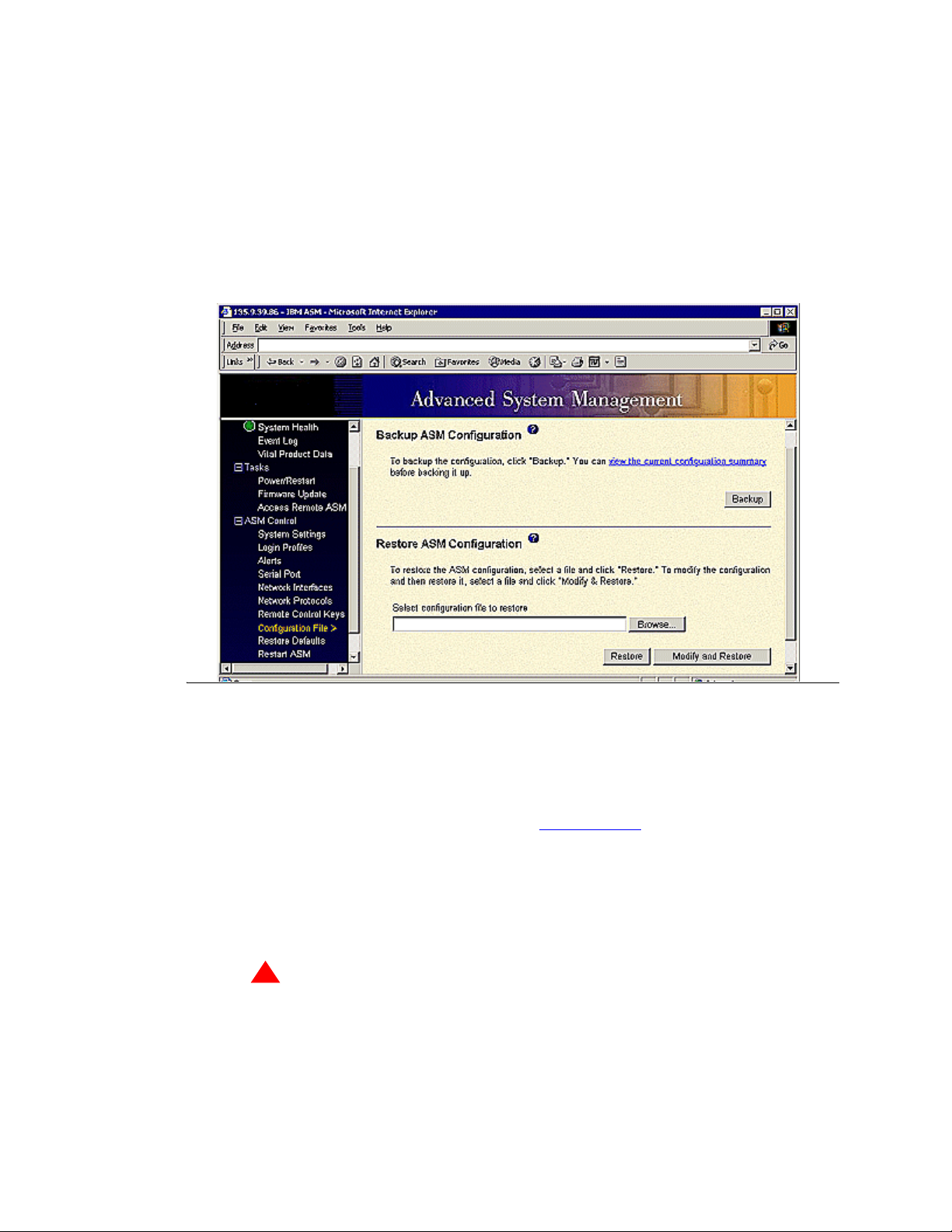
Configuring the Remote Supervisor Adapter
Restoring Advanced System Management configurations
You can restore a saved configuration or modify a saved configuration before restoring it by selecting
Configuration File from the navigation pane. Modifying a configuratio n before re storing it gives you the
ability to customize the configuration file for multiple RSAs.
1 Select Configuration File.
The system displays the Configuration window.
2 In the Restore ASM Configuration section, click Browse.
3 Find and click on the configuration file, then click Open.
The file, including the full path name, appears in the box.
NOTE:
To modify the file before restoring it, see Modifying a file on page 75.
4 Click Restore.
5 After Restore or Restore Configuration is selected, a progress indicator displays. The system
displays a confirmation window when the update is completed successfully.
6 Click Restart ASM, then Restart.
!
WARNING:
You must restart ASM for the new configuration to take affect.
7 Click OK to confirm that you would like to restart the RSA.
8 Click OK to close your current browser window.
74 Installing the Avaya S8500 Media Server with an Avaya G650 Media Gateway
December 2003
Page 75
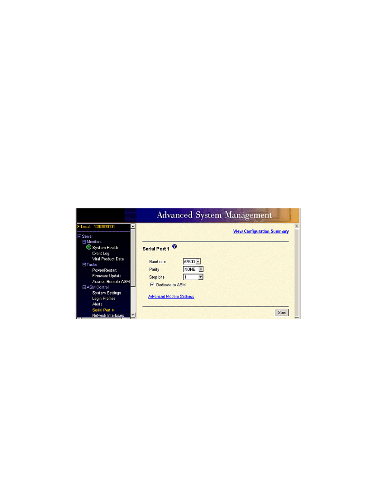
Modifying a file
Modifying a configuration before restoring it gives you the ability to customize the configuration file for
multiple RSAs.
1 Click Modify and Restore.
A new pane opens showing only the fields that can be modified.
2 Click on the text box corresponding to the field you wish to change and type in the new data.
3 To toggle between the view that you are modifying and the complete configuration view, click
Toggle View.
4 Once the changes to the configuration file have been made, see Restoring Advanced System
Management configurations on page 74 to restore the file.
Setting auto answer on the RSA card
You can determine how many times the phone will ring before the RSA card answers the call.
1 Under ASM Control, click Serial Port.
The system displays the Serial Port window.
Configuring the Remote Supervisor Adapter
2 In the Serial Port section, click Advanced Modem Settings.
The system displays the Modem Settings window.
Installing the Avaya S8500 Media Server with an Avaya G650 Media Gateway 75
December 2003
Page 76
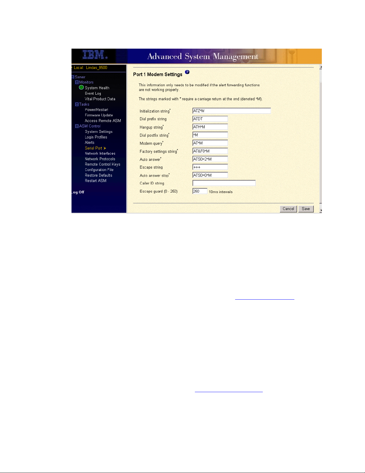
Configuring the Remote Supervisor Adapter
3 In the Auto Answer field, make sure this field is set at ATSO=3^M.
The 3 means the phone will ring 3 times before the RSA card answers the call.
Updating RSA or BIOS firmware
This option updates the firmware of the RSA or the server (BIOS) in which it is installed. Updating the
firmware also enables the BIOS code, diagnostics, power backplane, front panel, and the seri al peripheral
interface (SPI) of the server in which the RSA is installed.
If available, new RSA and BIOS firmware can be downloaded from http://support.avaya.com
To update the BIOS firmware:
1 Click on the file.
A download window opens.
2 Select the name and location for the file you are downloading and click OK.
A progress window opens as the files are transferred to the selected location. A confirmation
window opens when the transfer is completed.
3 Log in to the RSA.
4 In the navigation pane, select Firmware Update under the Tasks heading.
The Update Firmware window appears (see Figure 12, Update firmware,
.
on page 77).
76 Installing the Avaya S8500 Media Server with an Avaya G650 Media Gateway
December 2003
Page 77
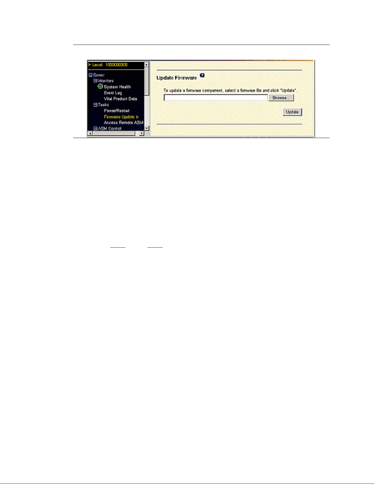
Configuring the Remote Supervisor Adapter
Figure 12: Update firmware
5 Click Browse. Go to the saved location from step 3.
6 Click Open to select the cnetbrus.pkt file and have it appear in the box beside Browse.
7 Click Update to begin the firmware update. A progress window opens as the fi le s are transf erred
to temporary storage on the RSA.
A confirmation window opens when the transfer is complete.
8 Verify that the file in the confirmation windo w is the file that you wish to use for the update. If
you do not wish to continue with the update, click Cancel.
9 To continue with the firmware update, click Continue.
A progress window opens as the firmware on the RSA updates. A confirmation window appears
when the update is completed.
10 Repeat Step 4 through Step 9 each time to update the cnetmnus.pkt and cnetrgus.pkt files.
NOTE:
You should update all three components (cnetbrus.pkt, cnetmnus.pkt and cnetr gus .pk t)
from the Avaya support website before restarting the RSA.
11 After you receive the confirmation window, click Restart to restart the RSA.
12 Click OK to continue with the restart.
13 Click OK to close the browser window.
14 Log in to the RSA.
Logging off the Remote Supervisor Adapter
1 Select Log Off from the left pane.
2 In the confirmation window, click Yes.
Installing the Avaya S8500 Media Server with an Avaya G650 Media Gateway 77
December 2003
Page 78

Configuring the network interface card
Configuring the network interface card
This section describes the steps required to configure the optional network interface card (NIC) on the
Avaya S8500 Media Server. The components of this procedure include:
• Confirming original Ethernet configuration on page 78
• Configuring the NIC on page 78
• Testing connectivity to customer’s network on page 79
Confirming original Ethernet configuration
After the Media Server is back in service, check the original Ethernet configuration settings:
1 Go to the Configure Server Web page.
2 Confirm that the server’s Ethernet configuration settings are the same as before.
Configuring the NIC
1 Under Server, click Configure Server
2 Click Continue through the review notices until you get to the xxx page.
3 Select Configure Individual Services and click Continue.
4 Select Set Identities and click Continue.
5 The following Ethernet ports are listed:
• Control Network A: [default: Ethernet 0]
• Services Port: [default: Ethernet 1]
• Corporate LAN: [default: Ethernet 0]
• Unused
6 Using the dro p-down m enu, set the Corporate LAN field to Ether net 2 to have the IP SI control on
a dedicated, separate Ethernet port.
7 Click Continue.
8 Fill in the following information for Ethernet 2:
• IP address
• Gateway
• Subnet mask
• Speed
9 Select "VLAN 802.1q priority tagging is enabled" if true.
10 Click Change. The status of the configuration update appears in the window.
When the update completes, the following message appears:
ethernet interfaces
78 Installing the Avaya S8500 Media Server with an Avaya G650 Media Gateway
.
Successfully configured
December 2003
Page 79
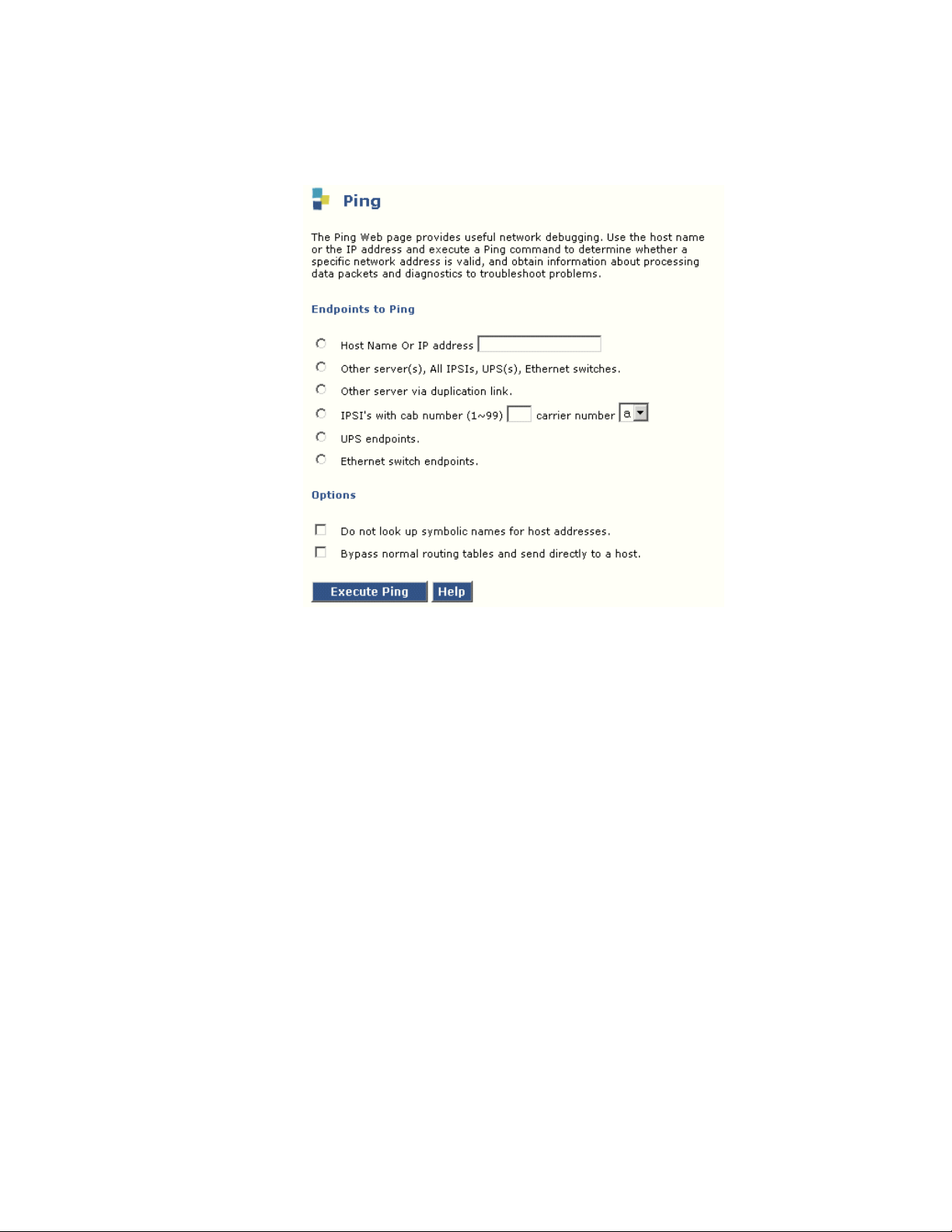
Testing connectivity to customer’s network
1 Under Diagnostics click Ping.
Configuring the network interface card
2 In the Select Host or IP address to Ping field, type in the IP address of a computer on the
network.
3 Click Execute Ping.
4 Verify that the ping was successful, indicating that the media server is connected to the cus tomer’s
network.
5 If DNS is administered, type in the host name of a computer on the network.
6 Click Execute Ping.
7 Verify that the ping was successful, indicating that DNS is working.
If available, have a customer representative do the following test from a computer on their network:
8 Click Start > Run to open the Run dialog box.
9 Type command and click OK to open an MS-DOS command window.
10 Type ping serveripaddress and click OK, where serveripaddress is the IP address of media
server.
11 Verify that the ping was successful.
12 If DNS is administered, type ping servername and press Enter, where servername is the host
name of media server.
13 Verify that the ping was successful.
Installing the Avaya S8500 Media Server with an Avaya G650 Media Gateway 79
December 2003
Page 80
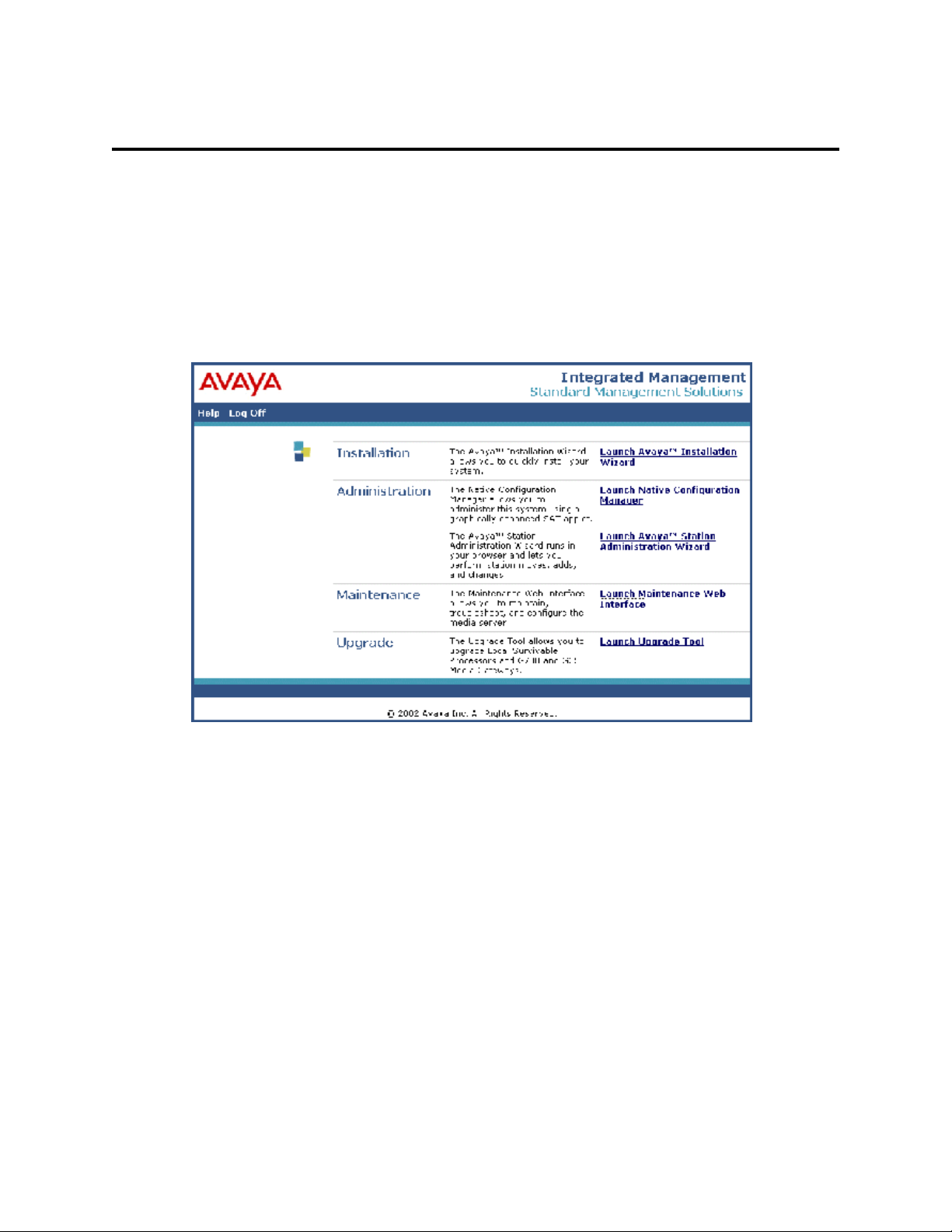
Configuring the modem
Configuring the modem
This section describes the steps required to administer modem settings on the media server.
1 On the Address field on an open browser, type the IP address or name of the Communication
Manager system.
The system opens the Integrated Management Standard Management Solutions window.
2 In the Logon window, in the Login ID field, type your login ID and click Logon.
3 In the Password field, type your password and click Logon.
The Integrated Management Standard Management Solutions window appears.
80 Installing the Avaya S8500 Media Server with an Avaya G650 Media Gateway
December 2003
Page 81
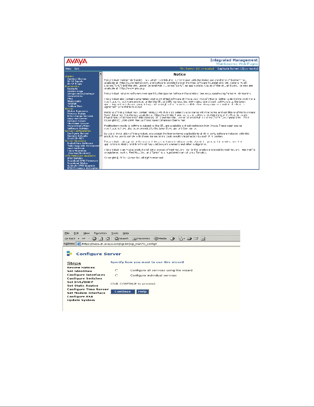
4 In the Maintenance section, click Launch Maintenance Web Interface.
The main menu window appears.
Configuring the modem
5 On the left menu, under Server Configuration, click Configure Server.
The Configure Server window appears.
6 On the Review Notices page, click Continue.
7 On the Warning page, click Continue.
8 On the Back Up Data page, click Continue.
The Specify how you want to use this wizard page appears.
Installing the Avaya S8500 Media Server with an Avaya G650 Media Gateway 81
December 2003
Page 82
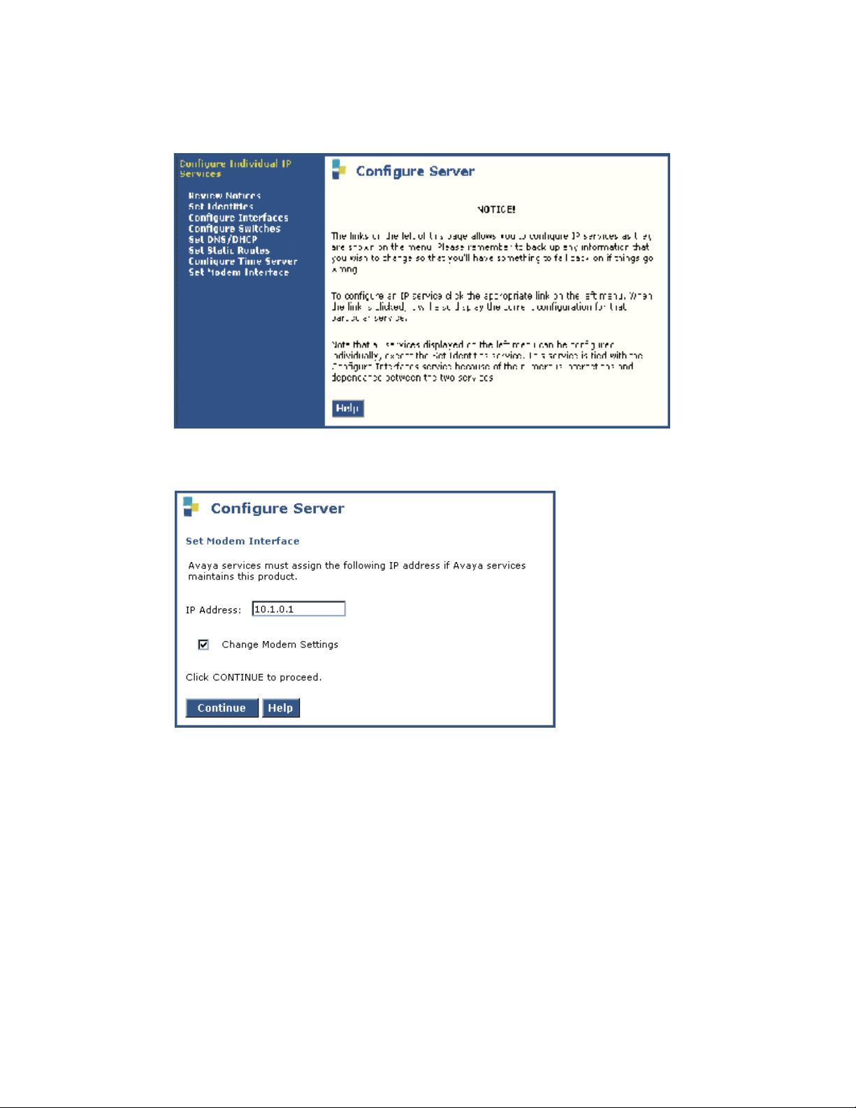
Configuring the modem
9 Click Configure individual services and then click Continue.
The Notice page with a menu appears.
10 In the left menu, click Set Modem Interface.
The Set Modem Interface window appears.
82 Installing the Avaya S8500 Media Server with an Avaya G650 Media Gateway
December 2003
Page 83
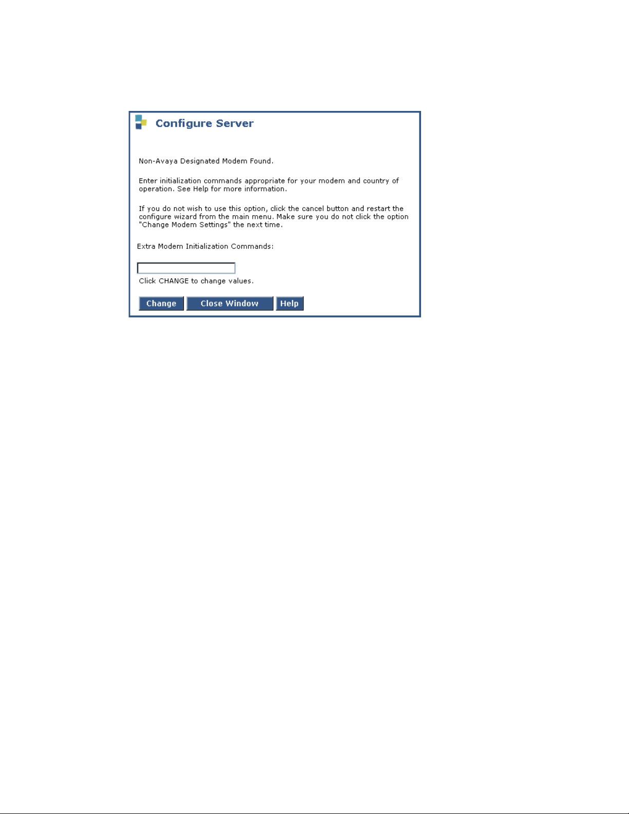
Configuring the modem
11 Select the Change Modem Setting and then click Continue.
The AT String window appears.
12 In the AT String field, type the initialization commands appropriate for your modem and country
of operation. Read the Help for guidance on what to enter.
For example, to change the country code to Japan, type the following command:
AT%T19,0,10
13 Click Change.
The system responds with a message indicating a successfully added modem route.
Installing the Avaya S8500 Media Server with an Avaya G650 Media Gateway 83
December 2003
Page 84

Configuring the SNMP modules in the uninterruptible power supplies
Configuring the SNMP modules in the uninterrupti bl e
power supplies
NOTE:
These instruction apply only if using a new, Avaya-supplied uninterruptible power supply
(UPS) with an simple network management protocol (SNMP) module. Do not use these
procedures to set traps on a non-Avaya-provided UPS.
The SNMP module in the UPS must be administered so it can report alarms to the appropriate media
server when the hardware experiences problems. The module reports the loss of commercial power
and/or the depletion of battery resources.
Each UPS’s SNMP module requires a unique IP address, which can be a customer-provided one or the
Avaya-provided default one. At a minimum, the following items need to be configured:
• IP address
• Default gateway IP address
• Subnet mask
• Community name strings (get, set, trap)
NOTE:
For the SNMP modules to properly report alarms, the IP addresses for the UPSs must also
be configured in the media servers.
See Setting selected traps (alarming)
on page 86 for information on which traps to set.
NOTE:
Because the SNMP module is manufactured by a third party, we do not know which
brand, model, or firmware load the factory is shipping. Therefore, we can not provide
specific instructions in this document on how to configure the SNMP module.
See the local configuration section of the User’s Guide that comes with the SNMP module for the default
password and the configur ation commands.
Use the following general procedures to administer the SNMP modules:
1 Make sure the UPS is plugged into a nonswitched electrical outlet.
2 Connect the services laptop computer (RS-232 serial port) to the DB-9 connector on the back of
the SNMP module for UPS 1 using the DB-9 to DB-9 serial cable supplied with the SNMP
module.
NOTE:
Avaya Terminal Emulation and HyperTerminal are supported terminal emulation
applications. Terranova is not supported.
3 On the services laptop open a VT-100 terminal emulation session using an application such as
Avaya Native Configuration Manager.
4 Administer the terminal emulation port settings:
• 9600 baud
• No parity
84 Installing the Avaya S8500 Media Server with an Avaya G650 Media Gateway
December 2003
Page 85

Configuring the SNMP modules in the uninterruptible power supplies
• 8 data bits
• 1 stop bit
• No flow control
5 Follow the instructions in User’s Guide.
6 Set the following parameters:
• IP address and subnet mask of the UPS. (defaults are 198.152.254.239, 255.255.255.0.)
•
•
•
IP address of the trap receiver. (default is 198.152.254.200)
• Default Gateway address of the UPS is 198.152.254.201.
NOTE:
If a Network Management System (NMS) is going to monitor the UPS units, coordinate
the assignment of community names with the network administrator (see the filled-out
Electronic Preinstallation Worksheet). If an NMS is not going to monitor the UPSs, set the
community names to unique string values.
• SNMP community string for Get, Set, and Trap.
SECURITY ALERT
The Get and Set, community name strings are generally configured with default values of Public and
Private, respectively. These community name strings function as passwords for their respective SNMP
operation. It is always a good idea to change these community name strings to something other than the
default values. If a Network Management Station is in operation on the network, whatever these values
are changed to must be coordinated with its administrator. If the defaults are left administered this could
create a serious security issue. For example, the default Set community name string, with it’s widely
known value of Private, could be used to shutdown power to the UPS loads via SNMP message.
7 When completed, disconnect the services laptop computer from the UPS.
8 Connect one end of a CAT5 cable to the RJ45 connector on the UPS’s SNMP module and the
other end to the next available port on the Ethernet switch for the control network.
Simplex reliability configurations
For simplex reliability configurations use the following address and cable connection information :
• UPS IP address / Subnet mask = 198.152.255.238 / 255.255.255.0
• Default Gateway IP address = 198.152.254.202
• Host Table trap receiver IP address = 198.152.254.202
• Local network administrator supplied information as required for Get and Set community name
strings.
Installing the Avaya S8500 Media Server with an Avaya G650 Media Gateway 85
December 2003
Page 86

Configuring the SNMP modules in the uninterruptible power supplies
Setting selected traps (alarming)
The default is to set all traps, which may result in large log entries. Therefore, only set the following
traps. See the User’s Guide that comes with the SNMP module for the menus and commands for setting
these traps.
• UPS on Battery—Indicates AC fail with pending shutdown based on battery reserve available
• UPS in Bypass—Failure either Failed UPS or overload
• Replace battery—Failure of periodic (28 -day ) battery test ind icating b atter y n eeds to be replaced.
86 Installing the Avaya S8500 Media Server with an Avaya G650 Media Gateway
December 2003
Page 87

Configuring the SNMP subagent in the Avaya Ethernet switch (if used)
Configuring the SNMP subagent in the A vaya Ethernet
switch (if used)
NOTE:
These instruction apply only if using a new, Avaya-supplied Avaya Ethernet switch. Do
not use these procedures to set traps on a non-Avaya-provided Ethernet switch.
The simple network management protocol (SNMP) subagent in the Avaya Ethernet switch must be
administered so it can report alarms to the media server when the hardware experiences problems.
Each Avaya Ethernet switch requires a unique IP address, which can be a customer-provided one or the
Avaya-provided default one. At a minimum, the following items need to be configured:
• IP address
• Subnet mask
• Trap receiver IP address
• Community string (get, set, trap)
NOTE:
For the Ethernet switch to properly report alarms, the IP address(es) for the Ethernet
switch(es) must also be configured in the media servers.
See the Basic Configuration section of the Quick Start Guide and the documentation CD that comes with
the Ethernet switch for the default user ID, password, and configuration commands.
Use the following general procedures to administer the Ethernet switch(es):
1 Plug the Ethernet switch power cord into the back of the switch and the back of a UPS.
• For Simplex reliability—connect Ethernet switch 1 for Control Network A (CNA) into
UPS 1
2 Connect the services lap top computer (R S-232 serial port) to the port lab eled Conso le on the front
of Ethernet switch 1 (CNA) using the flat cable supplied with the Avaya Ethernet switch.
3 On the services laptop open a VT-100 terminal emulation session using an application such as
Avaya Native Configuration Manager.
4 Administer the terminal emulation port settings:
• 9600 baud
• No parity
• 8 data bits
• 1 stop bit
5 Follow the instructions in the Quick Start Guide
6 Set the following parameters:
• IP address and subnet mask of the Ethernet switch (defaults are 198.152.254.240,
255.255.0.0.)
• IP address of the trap receiver. (default is 198.152.254.200)
• SNMP community string for Get, Set, and Trap. (See the chapter on SNMP commands on
the documentation CD that comes with the Avaya Ethernet switch.)
Installing the Avaya S8500 Media Server with an Avaya G650 Media Gateway 87
December 2003
Page 88

Configuring the SNMP subagent in the Avaya Ethernet switch (if used)
SECURITY ALERT
The Get and Set, community name strings are generally configured with default values of Public and
Private, respectively. These community name strings function as passwords for their respective SNMP
operation. It is always a good idea to change these community name strings to something other than the
default values. If a Network Management Station (NMS) is in operation on the network, whatever these
strings are changed to must be communicated to the NMS administrator. If the defaults are left
administered this could create a serious security issue. For example, the default Set community name
string, with it’s widely known value of Private, could be used to reconfigure the Ethernet switch via
SNMP message.
7 When completed, disconnect the services laptop computer from the Ethernet switch.
8 If two Ethernet switches are present for CNA, repeat steps 1 through 7 for the second switch.
88 Installing the Avaya S8500 Media Server with an Avaya G650 Media Gateway
December 2003
Page 89

Customizing the media server
For SAT commands, use a Native Configuration Manager, such as Avaya Terminal Emulator or
HyperTerminal. You also can use Avaya Site Administration, part of the Avaya Integrated Management
suite, which you can purchase from Avaya.
NOTE:
You must use Release 1.11 or a later version of Avaya Site Administration, to be able to
administer new features in Release 2.0 of Avaya Communication Manager.
Perform these tasks to customize the media server:
• Starting terminal emulation on page 89
• Inputing translations on page 89
• Resetting media server on page 90
• Adding media gateways on page 90
• Administering the IP server interface on page 90
• Saving translations on page 93
Customizing the media server
Starting terminal emulation
NOTE:
Avaya Terminal Emulation and HyperTerminal are supported terminal emulation
applications.
1 On the services laptop, open a VT-100 terminal emulation session.
2 Administer the terminal emulation port settings:
• 9600 baud
• No parity
• 8 data bits
• 1 stop bit
• No flow control
3 Log into the media server as craft.
Inputing translations
Contact the installation personnel responsible for translation input to download translations.
• Type save translations and press Enter to save the translations to the hard drive.
If the translations are not ready, you may continue with the process, entering minimal translations to
verify connectivity to the port networks.
Installing the Avaya S8500 Media Server with an Avaya G650 Media Gateway 89
December 2003
Page 90

Customizing the media server
Resetting media server
NOTE:
Do not reset the media server if no translations were input or if they were not entered in
bulk.
• Type reset system 4 and press Enter to have the call processing software read the copied
translations.
Adding media gateways
NOTE:
Do this procedure only if the translations were not input earlier.
NOTE:
A cabinet is defined as up to 5 G650 Media Gateways mounted in a rack and TDMconnected.
1 Type add cabinet number (1 through 64) and press Enter for each G650 Media Gateways stack
controlled by one TN2312BP IPSI circuit pack.
2 Fill in the location and carrier type for media gateways 2, 3, 4, and 5.
add cabinet 1 Page 1 of 1
CABINET DESCRIPTION
Cabinet: 9
Cabinet Layout: G650-rack-mount-stack
Cabinet Type: expansion-portnetwork
Location: 1
Rack: Room: Floor: Building:
CARRIER DESCRIPTION
Carrier Carrier Type Number
E not-used PN 09
D not-used PN 09
C not-used PN 09
B G650-port PN 09
A G650-port PN 09
CABINET
Administering the IP server interface
NOTE:
This procedure enables the IPSI circuit packs and allows them to control the port
networks.
3 Type change system-parameters ipserver-interface and press Enter.Verify that the Primary
Control Subnet Address is correct.
The subnet address must match the most significant 3 octets (the first 3 groups of digits in the
subnet address) of the Server IP address.
90 Installing the Avaya S8500 Media Server with an Avaya G650 Media Gateway
December 2003
Page 91

Customizing the media server
An Asterisk (*) to the right of the
Subnet Address field means that although a subnet address is
displayed, it is not the correct one; Av aya Communication Manager does not have the subnet
information. After verifying the displayed information, su bmit this form with or without changes
to update Communication Manager with the correct subnet information.
1 Type change system-parameters ipserver-interface and press Enter.
change system-parameters ipserver-interface Page 1 of 1
IP SERVER INTERFACE (IPSI) SYSTEM PARAMETERS
SERVER INFORMATION
IPSI Host Name Prefix:
Primary Control Subnet Address: 172. 22. 0. 0*
Secondary Control Subnet Address: . . .
OPTIONS
Switch Identifier: A
IPSI Control of Port Networks: enabled
NOTE: * indicates data changed on the server
2 Verify that the Primary Control Subnet Address is correct.
The subnet address must match the most significant 3 octets (the first 3 groups of digits in the
subnet address) of the Server IP address.
An Asterisk (*) to the right of the
Subnet Address field means that although a subnet address is
displayed, it is not the correct one; Av aya Communication Manager does not have the subnet
information. After verifying the displayed information, su bmit this form with or without changes
to update Communication Manager with the correct subnet information.
CAUTION:
If the information displayed in the Subnet Address field is not correct, it must be
changed on the media server. Use the Maintenance Web Interface; under Server
Configuration and Upgrades, click Configure Server to change the media server
configuration. Then return here to perform this step.
3 Set the Switch Identifier: field to the switch ID letter (A thru J; A is the default setting).
4 Set the IPSI Control of Port Networks: field to enabled.
5 Press Enter to effect the change.
Adding IPSI information
NOTE:
The information you provide differs, depending on whether the IPSIs get static addresses
or they are assigned automatically through DHCP.
1 Type add ipserver-interface PNnumber and press Enter to add the IPSI circuit pack
information.
Installing the Avaya S8500 Media Server with an Avaya G650 Media Gateway 91
December 2003
Page 92

Customizing the media server
2 When using a DHCP ser ver, verify that the fields associated with the Primary IPSI and Secondary
IPSI (if equipped) are populated with default data.The Host: and DHCP ID: fields are set by
the DHCP server.
add ipserver-interface 4 Page 1 of 1
IP SERVER INTERFACE (IPSI) ADMINISTRATION - PORT NETWORK 4
IP Control? y Socket Encryption? n
Enable QoS? n
Primary IPSI
----------- Location: 9A01
Host: ipsi-A09a
DHCP ID: ipsi-A09a
Secondary IPSI
------------- Location: 9B01
Host: ipsi-A09b
DHCP ID: ipsi-A09b
When using static addressing, in the
network listed in the
add ipserver-interface 8
IP SERVER INTERFACE (IPSI) ADMINISTRATION - PORT NETWORK 8
IP Control? y Socket Encryption? y
Enable QoS? y
Primary IPSI QoS Parameters
------------ ------------- Location: 1A01 Call Control 802.1p: 6
Host: 172.22.22.174 Call Control DiffServ: 46
DHCP ID: ipsi-A01a
Secondary IPSI
------------- Location: 1B01
Host: 172.22.22.175
DHCP ID: ipsi-A01b
Location: field.
Host: field, type in the IP address for the IPSI in the port
3 Set the IP Control? field to y.
4 Verify that all the other fields are populated.
5 Press Enter to effect the changes.
6 Repeat steps 1 through 5 for each port network.
92 Installing the Avaya S8500 Media Server with an Avaya G650 Media Gateway
December 2003
Page 93
Customizing the media server
Setting IPSI duplication (high/critical reliability only)
1
Type change system-parameters duplication and press Enter
change system-parameters duplication Page 1 of 1
DUPLICATION RELATED SYSTEM PARAMETERS
Enable Operation of PNC Duplication? y
Enable Operation of IPSI Duplication? y
2 Set the Enable Operation of IPSI Duplication? field to y.
3 Press Enter to effect the changes.
Setting alarm activation level
1 Type change system-parameters maintenance and press Enter.
change system-parameters maintenance Page 1 of 3
MAINTENANCE-RELATED SYSTEM PARAMETERS
OPERATIONS SUPPORT PARAMETERS
CPE Alarm Activation Level: none
SCHEDULED MAINTENANCE
Start Time: 22 : 00
Stop Time: 06 : 00
Save Translation: daily
Update LSPs When Saving Translations: y
Command Time-out (hours): 2
Control Channel Interchange: no
System Clocks/IPSI Interchange: no
2 In the CPE Alarm Activation Level field, select none (default), warning, minor, or major,
depending on the level the customer wants and press
Enter to effect the changes.
3 Repeat for each IPSI.
Installing the translation file
1 Type reset system 4 and press Enter to copy the translation files to the hard drive.
2 Type save translations and press Enter to save the translations to the hard drive.
Saving translations
• Type save translations and press Enter to save the IPSI translations to the hard drive.
Installing the Avaya S8500 Media Server with an Avaya G650 Media Gateway 93
December 2003
Page 94

Installing the media gateways
Installing the media gateways
Floor plans and equipment layouts for typical media gateway installations are provided in the Overview
section of the documentation library.
Media gateways typically are installed in the same equipment room as the media server rack hardware
(control network); however, they can be installed in another location, including another state or country.
NOTE:
Before you begin the media gateway installation, check the location of the AC/DC power
receptacles. The receptacles must be on separately fused circuits not controlled by wall
switches. They must be located within 10 feet (3 met ers) of the medi a gateway and outside
the main distribution frame (MDF) area.
NOTE:
For convenience, we recommend installing the reference IPSI, the one associated with the
license file, in a port network in the same room as the control network hardware.
Before installing the media gateways, you must check to make sure you have all the required equipment
and are aware of warnings when working around sources of power. Perform these tasks to install the
media gateway:
• Checking and inspecting the order on page 96
• Connecting AC power and ground on page 99.
• Installing the G650 Media Gateway on page 100
• Cabling the G650 Media Gateways on page 121
• Installing an MCC1 Media Gateway on page 126
• Cabling the MCC1 Media Gateways—center stage switch on page 159
• Installing the G350 Media Gateway on page 163
• Installing the G700 Media Gateway on page 165
• Installing patch panels on page 167
The Avaya S8500 Media Server works with either a G650, MCC1, SCC1, G600, or CMC1 Media
Gateway. In addition a G700 Media Gateway may be used if one of the other media gateways with a
TN799DP Control-LAN (C-LAN) circuit pack is installed.
This section provides procedures for:
NOTE:
New installations are provided with only the G650 Media Gateway.
• Installing the G650 Media Gateway on page 100
• Installing an MCC1 Media Gateway on page 126
NOTE:
MCC1 Media Gateways are only provided when a center stage switch (CSS) carrier is
required. The MCC1 Media Gateway will contain one port network in the A, B, C, and D
positions and the CSS carrier in the E position. For critical reliability system s, the D
position also may be used for the duplicated (B-PNC) CSS carrier.
94 Installing the Avaya S8500 Media Server with an Avaya G650 Media Gateway
December 2003
Page 95

Installing the media gateways
• Installing the G350 Media Gateway on page 163
• Installing the G700 Media Gateway on page 165
In addition to installing the media gateways, you may need to install a MDF and connect the media
gateways to it and connect it to stations and to the public switched telephone network (PSTN). For more
information, check the following sections:
• Installing the main distribution frame on page 170
• Connecting the media gateway to the main distribution frame on page 185
• Connecting the main distribution frame to stations and the public switched telephone network on
page 191
Installing the Avaya S8500 Media Server with an Avaya G650 Media Gateway 95
December 2003
Page 96

Checking and inspecting the order
Perform these tasks before you begin the installation:
• Checking the customer’s order on page 96
• Unpacking and inspecting the media gateways—G650 on page 96
• Checking circuit packs on page 97
• Unpacking and inspecting the media gateways—MCC1 on page 98
• Correcting shipping errors on page 98
Checking the customer’s order
Check the customer’s order and the shipping packing lists to confirm that all equipment is
1
included.
2 Check the system adjuncts for damage and report all damage according to local shipping
instructions.
3 If any equipment is missing, report the information to your Avaya representative.
Unpacking and inspecting the media
gateways—G650
!
DANGER:
Use lifting precautions. An empty G650 Media Gateway weighs 35-39 pounds (16-18
kilograms). Use caution to avoid injury.
1 Unpack the media gateway and remove all packing material.
2 Verify the equipment received. See Figure 13, Equipment packed with a single G650 Media
Gateway, on page 97. Actual equipment may vary in appearance and may ship in separate
packages.
NOTE:
The optional G650 Media Gateways for port hardwa re only are shi pped with AC o r DC
power cord or international power cord kit, mounting screw kits, TDM/LAN bus cable,
and EMI Gaskets.
96 Installing the Avaya S8500 Media Server with an Avaya G650 Media Gateway
December 2003
Page 97
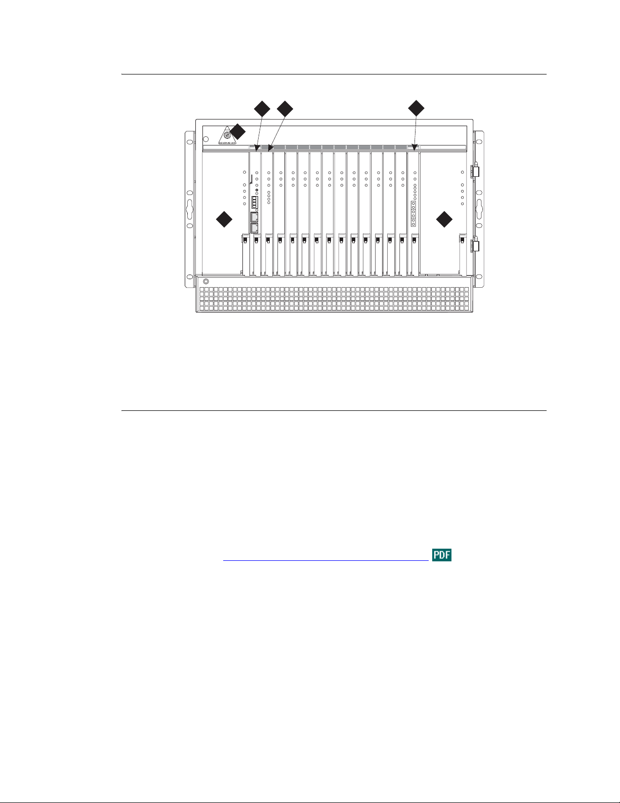
Figure 13: Equipment packed with a single G650 Media Gateway
3 4
1
1
2
FAN OR POWER FAIL
FAN AND POWER OK
AC INPUT
DC INPUT
ACTIVE RING
2
Figure notes
1 ESD ground jack
2 655A power supp ly
3 TN2312BP IP server interface (IPSI)
circuit pack
5
6 8 9Power
5
7 11
103 4
13 Power
14
12
FAN OR POWER FAIL
FAN AND POWER OK
AC INPUT
DC INPUT
ACTIVE RING
2
scdlff02 LAO 081203
4 TN799DP CLAN (optional)
5 TN2302 IP media processor (optional)
Checking circuit pack s
1 Be sure all circuit packs are fully inserted into the proper slots according to the system diagram
provided by the project manager.
Report any discrepancies in circuit pack type or quantity to your Avaya representative.
For detailed circuit pack descriptions, see the Hardware Guide for the Avaya Communication
Manager
The job aid titled Pre-I nstalla tion Info rmati on - S8500 Media Server
lists the comcodes for
equipment used with the G650 Media Gateway. If “Optional” is indicated, the equipment may or
may not be necessary, depending on the site configuration.
2 Check the any adjuncts shipped for damage and report all damage according to local shipping
instructions.
Installing the Avaya S8500 Media Server with an Avaya G650 Media Gateway 97
December 2003
Page 98

Unpacking and inspecting the media
gateways—MCC1
!
DANGER:
Use lifting precauti ons. A ful ly load ed MCC1 Medi a Gate way weigh s as much as 8 00
pounds (363 kilograms) and may be top heavy. Use caution to avoid injury.
1 Check the status of the SHOCKWATCH and/or TILTWATCH indicators on the container. If the
container has been shaken or tilted beyond specifications, the indicators are red, indicating
potential damage. Report any damage according to local shipping instructions.
!
DANGER:
Take care to avoid injury while cutting and removing the 2 metal bands.
2 Unpack the media gateway and remove all packing material.
3 Move the media gateway into its proper position.
4 Do not adjust the leveling feet at this time.
Correcting shipping errors
1 Red-tag all defective and over-shipped equipment and return according to the nearest Material
Stocking Location (MSL) instructions.
To contact the Avaya Order Management group in the United States, call 1-800-772-5409. For
international customers, contact your order service agent.
2 Direct all short-shipped reports to the nearest MSL. Contact the appropriate location for specific
instructions.
For streamlined implementation, call 1-800-772-5409.
98 Installing the Avaya S8500 Media Server with an Avaya G650 Media Gateway
December 2003
Page 99
Connecting AC power and ground
When installing media gateways, be aware of the following warnings and cautions.
!
WARNING:
The equipment room alternating current (AC) power and ground wiring must be performed by a
qualified electrician. The AC power circuit must be d edicated to the system. The circu it must not be
shared with other equipment and must not be controlled by a wall switch. The AC receptacle must
not be located under the main distribution frame and must be easily accessible.
CAUTION:
Media gateway grounding must comply with the general rules for grounding contained in
Article 250 of the National Electrical Code (NEC), National Fire Protection Agency
(NFPA) 70, or the applicable electric code in the country of installation. For more
information, see the job aid titled Approved Grounds
!
DANGER:
The latch on the power supply does not remove power from the G650 Media
Gateway. To remove the AC power from the 655A, pull the AC power cord from the
back of the G650 Media Gateway. If there are redundant power supplies, you need to
pull both AC power cords from the back of the G650 Media Gateway. To remove DC
power, first locate and switch the DC circuit breaker to the "off" position and then
disconnect the DC power feed at the back of the G650 Media Gateway.
.
!
WARNING:
With an G650 Media Gateway if other equipment is installed in the same rack, make sure that the
media gateway does not generate an overcurrent or overload condition. Verify that the customer’s
branch circuit and/or power distribution strip are ad equate with respect to over load and ov ercurrent
protection.
Approved grounds
See the job aid entitled Approved Grounds.
Installing the Avaya S8500 Media Server with an Avaya G650 Media Gateway 99
December 2003
Page 100
Installing the G650 Media Gateway
Perform these tasks to install the G650 Media Gateway port network:
• Checking circuit packs on page 103
• Checking the ventilation and the G650 Media Gateway rack on page 105
• Setting the carrier address ID on page 106
• Mounting one G650 Media Gateway on page 108
• Mounting two to five G650 Media Gateways on page 112
• Installing the TN2312BP IPSI adapter on page 112
• Approved ground on page 113
• Connecting the G650 Media Gateway grounds and other grounds on page 113
• AC power on page 115
• DC power on page 117
• Uninterruptible power supply on page 118
• G650 Media Gateway power switch on page 119
Table 6, Comcodes for the G650,
G650.
T a ble 6: Comcodes for the G650 1 of 4
Comcode Description
700259724 G650 cabinet (includes one 655A power supply) Yes No Yes
105631527 Bus terminators (AHF110 circuit packs) for an A
carrier
405289547 Cabinet feet for an A carrier mounted on the floor Yes No Yes
840059885 Cabinet feet screws for an A carrier mounted on the
floor
700260359 TN2312BP IP server interface circuit pack Yes No Yes
700055015 TN799DP CLAN Yes No Yes
108774696 TN2302AP IP media processor Yes No Yes
848525887 IP media processor adapter (TN2302, TN799DP) No No Yes
on page 100 shows the list of equipment and their comcodes for the
Included
in basic
cabinet
Yes Must have one
Yes No Yes
Optional
bus terminator
for each G650
or G650 stack
FRU
Yes
102631413 259A adapter for C-LAN (TN799C) No No Yes
700252638 DC feed power cable (Cable from the customer’s DC
plant to the cabinet backplane. Defaults to 30 feet in
length)
405362641 AC power cord—Domestic (USA, Canada, Mexico,
Japan, and much of the Caribbean)
100 Installing the Avaya S8500 Media Server with an Avaya G650 Media Gateway
Yes No
Yes No
*
*
December 2003
Yes
Yes
 Loading...