

Avaya ERS 5510, ERS 5530, ERS 5520 Technical Configuration Manual

Ethernet Routing Switch
5510/5520/5530
Engineering
Filters and QOS
Configuration for Ethernet
Routing Switch 5500
Technical Configuration
Guide
Enterprise Solutions Engineering
Document Date: January 2013
Document Number: NN48500-559
Document Version: 2.2

Filt
2
January 2013
avaya.com
© 2013 Avaya Inc.
All Rights Reserved.
Notices
While reasonable efforts have been made to ensure that the information in this document is complete and accurate at the time of
printing, Avaya assumes no liability for any errors. Avaya reserves the right to make changes and corrections to the information in
this document without the obligation to notify any person or organization of such changes.
Documentation disclaimer
Avaya shall not be responsible for any modifications, additions, or deletions to the original published version of this documentation
unless such modifications, additions, or deletions were performed by Avaya. End User agree to indemnify and hold harmless Avaya,
Avaya‟s agents, servants and employees against all claims, law s uits, demands and judgments arising out of, or in connection with,
subsequent modifications, additions or deletions to this documentation, to the extent made by End User.
Link disclaimer
Avaya is not responsible for the contents or reliability of any linked Web sites referenced within this site or documentation(s)
provided by Avaya. Avaya is not responsible for the accuracy of any information, statement or content provided on these sites and
does not necessarily endorse the products, services, or information described or offered within them. Avaya does not guarantee that
these links will work all the time and has no control over the availability of the linked pages.
Warranty
Avaya provides a limited warranty on this product. Refer to your sales agreement to establish the terms of the limited warranty. In
addition, Avaya‟s standard warranty language, as well as information regarding support for this product, while under warranty , is
available to Avaya customers and other parties through the Avaya Support Web site: http://www.avaya.com/support
Please note that if you acquired the product from an authorized reseller, the warranty is provided to you by said reseller and not by
Avaya.
Licenses
THE SOFTWARE LICENSE TERMS AVAILABLE ON THE AVAYA WEBSITE, HTTP://SUPPORT.AVAYA.COM/LICENSEINFO/
ARE APPLICABLE TO ANYONE WHO DOWNLOADS, USES AND/OR INSTALLS AVAYA SOFTWARE, PURCHASED FROM
AVAYA INC., ANY AVAYA AFFILIATE, OR AN AUTHORIZED AVAYA RESELLER (AS APPLICABLE) UNDER A COMMERCIAL
AGREEMENT WITH AVAYA OR AN AUTHORIZED AVAYA RESELLER. UNLESS OTHERWISE AGREED TO BY AVAYA IN
WRITING, AVAYA DOES NOT EXTEND THIS LICENSE IF THE SOFTWARE WAS OBTAINED FROM ANYONE OTHER THAN
AVAYA, AN AVAYA AFFILIATE OR AN AVAYA AUTHORIZED RESELLER, AND AVAYA RESERVES THE RIGHT TO TAKE
LEGAL ACTION AGAINST YOU AND ANYONE ELSE USING OR SELLING THE SOFTWARE WITHOUT A LICENSE. BY
INSTALLING, DOWNLOADING OR USING THE SOFTWARE, OR AUTHORIZING OTHERS TO DO SO, YOU, ON BEHALF OF
YOURSELF AND THE ENTITY FOR WHOM YOU ARE INSTALLING, DOWNLOADING OR USING THE SOFTWARE
(HEREINAFTER REFERRED TO INTERCHANGEABLY AS "YOU" AND "END USER"), AGREE TO THESE TERMS AND
CONDITIONS AND CREATE A BINDING CONTRACT BETWEEN YOU AND AVAYA INC. OR THE APPLICABLE AVAYA
AFFILIATE ("AVAYA").
Copyright
Except where expressly stated otherwise, no use should be made of the Documentation(s) and Product(s) provided by Avaya. All
content in this documentation(s) and the product(s) provided by Avaya including the selection, arrangement and design of the
content is owned either by Avaya or its licensors and is protected by copyright and other intellectual property laws including the sui
generis rights relating to the protection of databases. You may not modify, copy, reproduce, republish, upload, post, transmit or
distribute in any way any content, in whole or in part, including any code and software. Unauthorized reproduction, transmission,
dissemination, storage, and or use without the express written consent of Avaya can be a criminal, as well as a civil offense under
the applicable law.
Third Party Components
Certain software programs or portions thereof included in the Product may contain software distributed under third party agreements
("Third Party Components"), which may contain terms that expand or limit rights to use certain portions of the Product ("Third Party
Terms"). Information regarding distributed Linux OS source code (for those Products that have distributed the Linux OS source
code), and identifying the copyright holders of the Third Party Components and the Third Party Terms that apply to them is available
on the Avaya Support Web site: http://support.avaya.com/Copyright.
Trademarks
The trademarks, logos and service marks ("Marks") displayed in this site, the documentation(s) and product(s) provided by Avaya
are the registered or unregistered Marks of Avaya, its affiliates, or other third parties. Users are not permitted to use such Marks
without prior written consent from Avaya or such third party which may own the Mark. Nothing contained in this site, the
documentation(s) and product(s) should be construed as granting, by implication, estoppel, or otherwise, any license or right in and
to the Marks without the express written permission of Avaya or the applicable third party. Avaya is a registered trademark of Avaya
Inc. All non-Avaya trademarks are the property of their respective owners.
Downloading documents
For the most current versions of documentation, see the Avaya Support. Web site: http://www.avaya.com/support.
Contact Avaya Support
Avaya provides a telephone number for you to use to report problems or to ask questions about your product. The support
telephone number is 1-800-242-2121 in the United States. For additional support telephone numbers, see the Avaya Web site:
http://www.avaya.com/support.
Filters and QOS Configuration for Ethernet Routing Switch 5500
Technical Configuration Guide

Filt
3
January 2013
avaya.com
Abstract
This technical configuration guide provides an overview on how to configure QoS and Filters on the
Ethernet Routing Switch 5500 with software release 5.1. The configuration examples are all in reference
to the Avaya Command Line Interface (ACLI).
Filters and QOS Configuration for Ethernet Routing Switch 5500
Technical Configuration Guide

Filt
4
January 2013
avaya.com
Table of Contents
Document Updates ...........................................................................................................................6
Conventions .....................................................................................................................................6
1. Overview: Ethernet Routing Switch 5500 QoS and Filtering................................ ......................7
2. QoS Flow Chart .......................................................................................................................10
3. Filter Functionality...................................................................................................................11
3.1 Overall Classification Functionality ......................................................................................11
3.2 Classifier Block Functionality ..............................................................................................11
3.3 Port Range Functionality ....................................................................................................12
3.4 Policies .............................................................................................................................14
4. Queue Sets ..............................................................................................................................16
5. Traffic Meter and Shaping .......................................................................................................21
5.1 Actual Bucket Size .............................................................................................................22
5.2 Policing Traffic ...................................................................................................................22
5.3 Interface Shaper ................................................................................................................24
6. Default Avaya Class of Service................................................................ ................................26
7. QoS Access Lists (ACL) ..........................................................................................................27
7.1 ACL Configuration..............................................................................................................27
8. IP Security Features ................................................................................................................32
8.1 DHCP Snooping ................................................................................................................32
8.2 Dynamic ARP Inspection ................................ ................................................................ ....33
8.3 IP Source Guard ................................................................................................................33
9. BPDU Filtering ................................................................ ......................................................... 34
9.1 BPDU Filtering Configuration ..............................................................................................34
10. QoS Interface Applications ..................................................................................................35
10.1 ARP Spoofing ................................ ................................................................ ....................36
10.2 DHCP Attacks.................................................................................................................... 37
10.3 DoS ................................................................................................................................ ..38
10.4 BPDU Blocking ..................................................................................................................39
11. Configuration Steps – Policy Configuration ........................................................................40
11.1 Role Combination ..............................................................................................................40
11.2 Classification .....................................................................................................................41
11.3 Meters................................................................................................ ...............................43
11.4 Add a New Policy................................................................ ...............................................44
12. Configuration Examples ......................................................................................................45
12.1 Pre-defined Values................................ ................................................................ .............45
12.2 Configuration Example 1 – Traffic Meter Using Policies ........................................................46
12.3 Configuration Example – IP ACL, DHCP Snooping, ARP Inspection, BPDU Filtering, and
Source Guard ...............................................................................................................................52
Filters and QOS Configuration for Ethernet Routing Switch 5500
Technical Configuration Guide

Filt
5
January 2013
avaya.com
12.4 Configuration Example 3: Port Range Using ACL or Policy ...................................................61
12.5 Configuration Example 4 – L2 Classification Based on MAC Address ....................................64
12.6 Configuration Example 5 – L2 and L3 Classification .............................................................66
12.7 Configuration Example 6 - QoS Marking with Port Role Combination set for Un-restricted using
ACL‟s 68
12.8 Configuration Example 7 – Interface Shaping.......................................................................71
13. Software Baseline ................................................................................................................72
14. Reference Documentation ...................................................................................................72
15. Customer service................................ ................................................................ .................73
15.1 Getting technical documentation .........................................................................................73
15.2 Getting product training ......................................................................................................73
15.3 Getting help from a distributor or reseller .............................................................................73
15.4 Getting technical support from the Avaya Web site...............................................................73
List of Figures
Figure 1: QoS System Diagram ...........................................................................................................7
Figure 2: QoS Flow Chart ..................................................................................................................10
Figure 3: Arp Spoofing Example ........................................................................................................36
Figure 4: IP ACL, DHCP Snooping, ARP Inspection, and Source Guard...............................................52
Figure 5: L2 Classification Based on MAC Address Example ...............................................................64
Figure 6: DSCP Mapping via Un-restricted Port Role...........................................................................68
List of Tables
Table 1: Default QoS Action ................................................................................................................8
Table 2: Example of Valid Port Ranges ..............................................................................................13
Table 3: Default Policy Drop Action ....................................................................................................15
Table 4: Ethernet Routing Switch 5500 Resource Sharing ...................................................................16
Table 5: Ethernet Routing Switch 5500 Egress CoS Queuing ..............................................................17
Table 6: Meter and Shaping Range and Granularity ............................................................................21
Table 7: Actual Bucket Size in Bytes ..................................................................................................22
Table 8: Meter Bucket Size and Duration................................................................ ............................24
Table 9: Default Avaya CoS Markings ................................................................................................26
Table 10: QoS Applications – Number of Classifiers Used ...................................................................35
Filters and QOS Configuration for Ethernet Routing Switch 5500
Technical Configuration Guide

Filt
6
January 2013
avaya.com
Tip – Highlights a configuration or technical tip.
Note – Highlights important information to the reader.
Warning – Highlights important information about an action that may result in equipment
damage, configuration or data loss.
Bold text indicates emphasis.
Italic text in a Courier New font indicates text the user must enter or select in a menu item, button
or command:
ERS5520-48T# show running-config
Output examples from Avaya devices are displayed in a Lucinda Console font:
ERS5520-48T# show running-config
! Embedded ASCII Configuration Generator Script
! Model = Ethernet Routing Switch 5520-24T-PWR
! Software version = v5.0.0.011
enable
configure terminal
Document Updates
Added ACL, DHCP Snooping, APP Inspection, BPDU Filtering and IP Source Guard.
Conventions
This section describes the text, image, and command conventions used in this document.
Symbols:
Text:
Filters and QOS Configuration for Ethernet Routing Switch 5500
Technical Configuration Guide
Filt
7
January 2013
avaya.com
Port
Classifier
Meter
Marker
Dropper
Queue
Redirecto
Actions
Counters / Statistics
Role Combinations
(ingress port group)
Egress
ports
Port
Port
Port
Queue
Queue
Queue
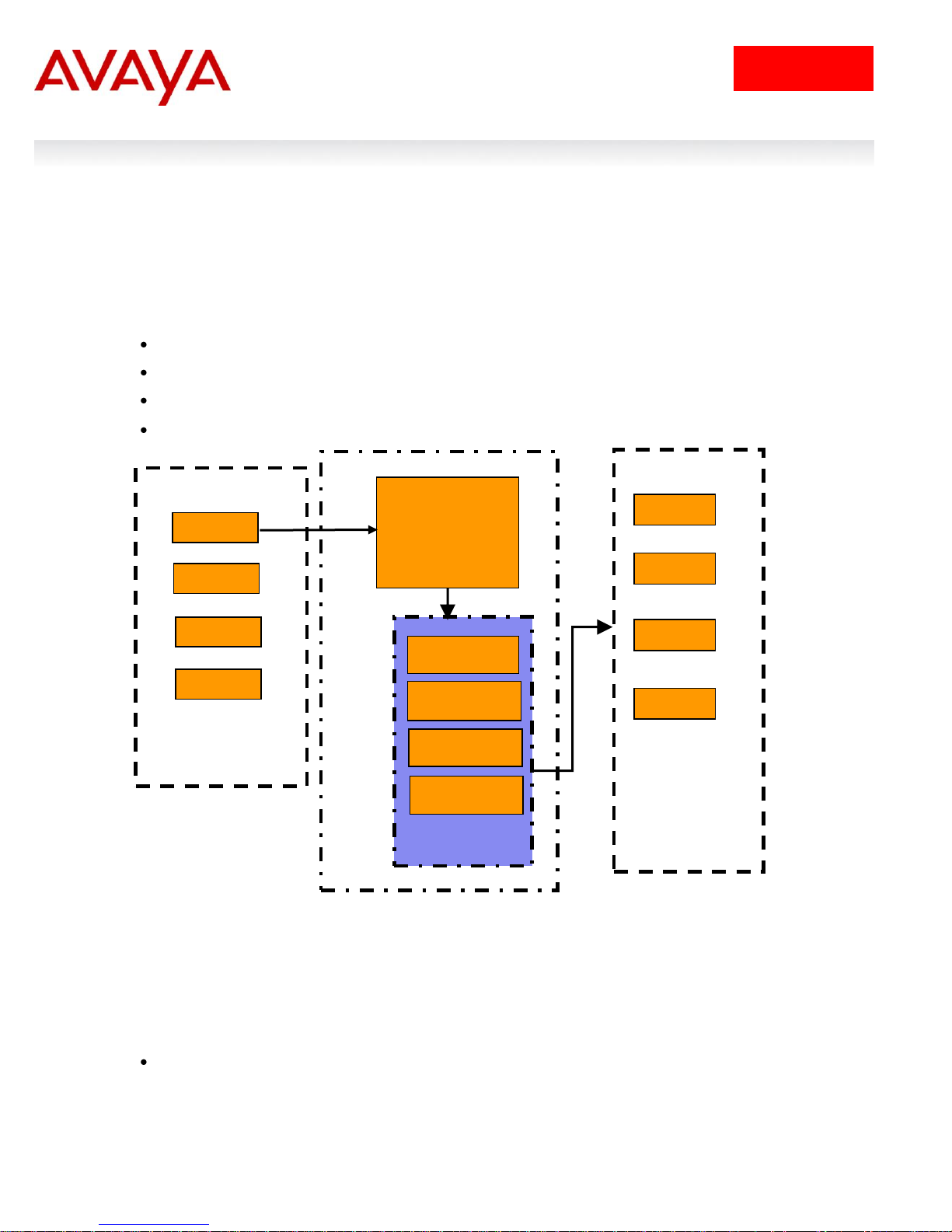
1. Overview: Ethernet Routing Switch 5500 QoS
and Filtering
The Ethernet Routing Switch 5500 supports QoS and filter configuration via WEB, CLI, and Device
Manager with no support for COPS at this time. As shown in the diagram below, the following functional
components provide QoS support on the Ethernet Routing Switch 5500:
Role Combination on the ingress port
Classify traffic at either Layer 2 or at a Layer 3/4 level
Take action by dropping, marking, redirecting, or metering (policing) traffic
Send traffic to appropriate egress queue
Figure 1: QoS System Diagram
Role Combination
A role combination is a grouping of one or more ports, capabilities, and interface classifications against
which a policy is applied. The capabilities presently supported on the Ethernet Routing Switch 5500
include ingress IP and Layer 2 classification. The Ethernet Routing Switch 5500 supports the following
interface classes that can be applied to zero, one, or many interfaces:
Trusted Ports
o Assumes that all traffic coming into the port is originating from a trusted source. Therefore,
the DSCP field of any traffic that enters the Et hernet Routing Switch 5500 from a Trusted Port
Filters and QOS Configuration for Ethernet Routing Switch 5500
Technical Configuration Guide
Filt
8
January 2013
avaya.com
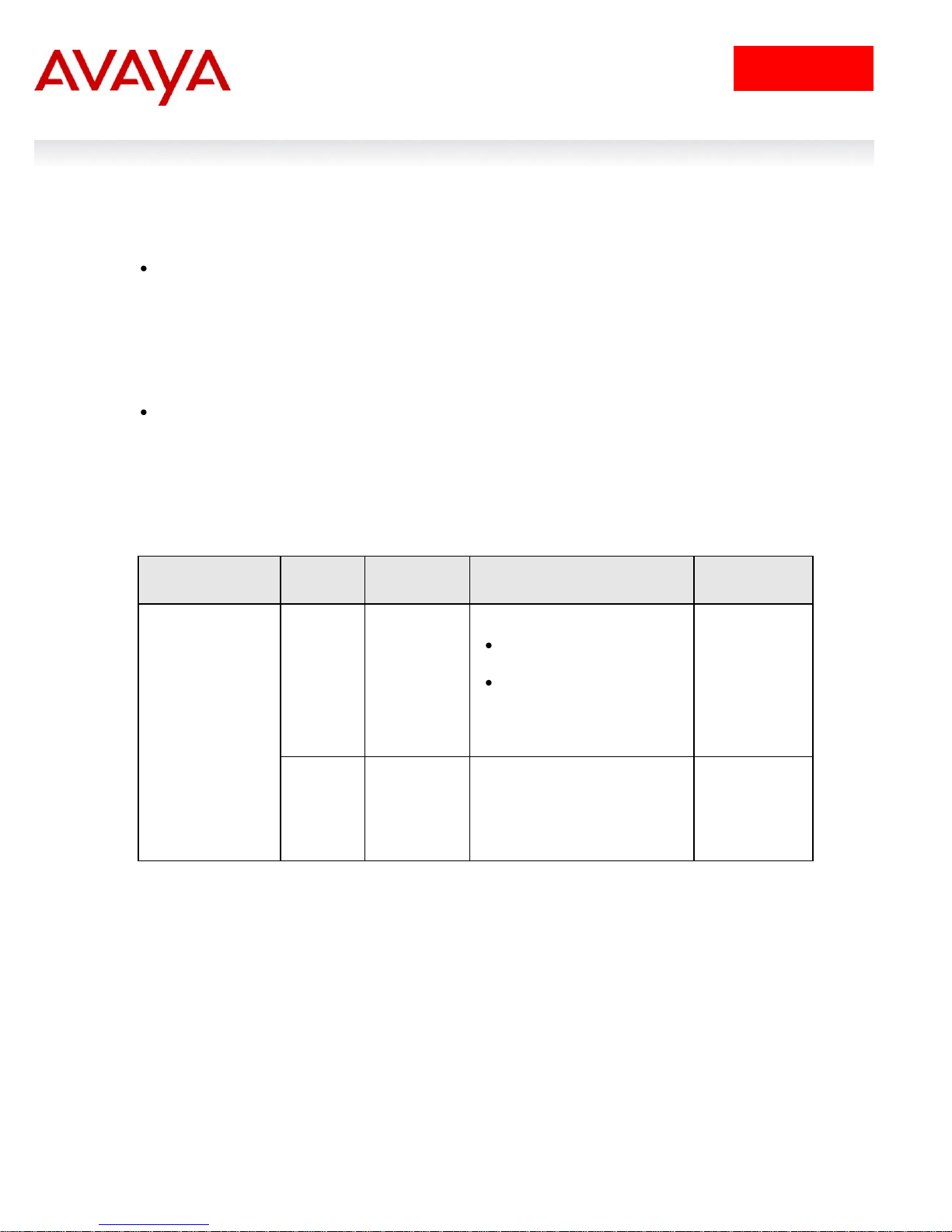
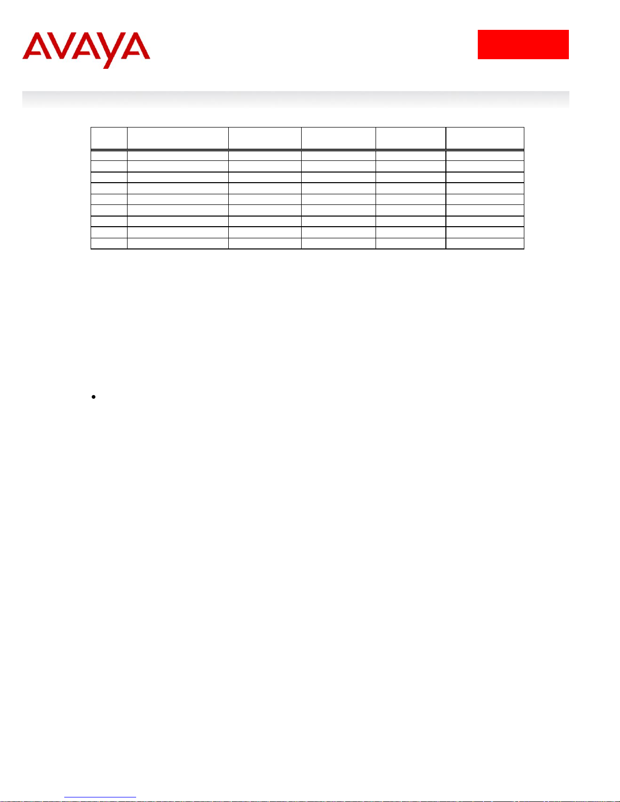
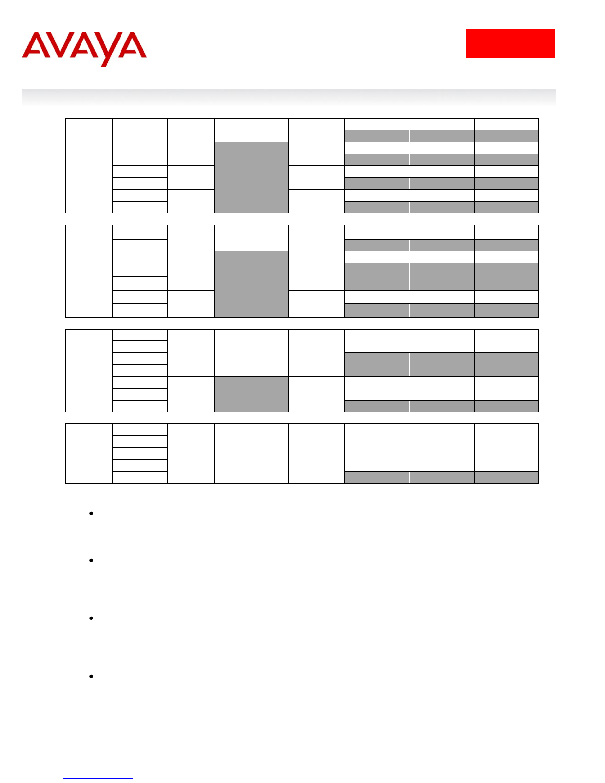
Type of Filter
Action
Trusted
Untrusted
Unrestricted
IPv4 filter criteria
or Layer 2 filter
criteria matching
IPv4
DSCP
Does not
change
Tagged--Updates to 0
(Standard)
Untagged--Updates using
mapping table and port‟s
default value
Does not
change
IEEE
802.1p
Updates
based on
DSCP
mapping
table value
Updates based on DSCP
mapping table value
Does not
change
is not remarked by default. However, a policy can still be applied to a trusted port to remark if
required. Note that only the 802.1p user priority value associated with „ well-k nown‟ DSCP
values are remapped by the default truste d polices. The „well-know‟ DSCP values can be
viewed by using the ACLI command „show qos eqressmap‟.
Untrusted Ports
o Assumes that all traffic coming into the port is suspect. Therefore, the DSCP field of any
traffic that enters the Ethernet Routing Switch 5500 from an Untrusted Port is re-marked. For
untagged packets, the default classifier is used to change the DSCP. This results in a DSCP
value determined by the CoS-to-DSCP mapping table using the default 802.1p priority of the
interface where the packet is received. For tagged packets, the 802.1p value is determined
by CoS-to-DSCP mapping table using the best effort DSCP, which is 0.
Unrestricted Ports
o Does not assume anything about the origin of the incoming traffic. You may assign an action
to set the DSCP or not to set the DSCP; it's up to you. This allows you to manipulate the
DSCP value based upon the filter criteria, and not upon the point of origin.
The following table displays a summary of the role combination capabilities.
Classification
Classification identifies the traffic flow that requires QoS management. The traffic flow may be identified
by the Layer 2 or IP content of the frame using any of the elements shown below.
Layer 2 Classifier Elements
o Source MAC with mask to filter on complete or partial MAC addresses
o Destination MAC with mask to filter on complete or partial MAC addresses
o VLAN ID – can be a range
o Tagged or untagged packets
o EtherType
o 802.1p priority
Filters and QOS Configuration for Ethernet Routing Switch 5500
Table 1: Default QoS Action
Technical Configuration Guide

Filt
9
January 2013
avaya.com
IP Classifier Elements
o Source IPv4/v6 host or subnet
o Destination IPv4/v6 host or subnet
o IPv4/v6 DSCP value
o IPv4 Protocol type, IPv6 next-header
o IPv4/v6 Layer 4 (UDP/TCP) Source port – can be range of ports
o IPv4/v6 Layer 4 (UDP/TCP) Destination port – can be range of ports
o IPv6 flow identifier
A classifier can contain one Layer 2 element, one IP element, or one Layer 2 and one IP element. One or
more classifiers can be combined to create a classifier block where up to 15 classifiers and/or classifier
blocks can be assigned to a port. By using classifier blocks, the number of classifiers can be increased up
to a total of 114 classifiers per port on the Ethernet Routing Switch 5500 for a total of over 40K in a stack.
In addition, statistic counters can be used to match/in-profile and out-of-profile statistics with meter. Up to
32 match/in-profile counters and 63 out-of-profile counters (one per meter) are supported per interface.
Actions Supported
After matching a certain classification criteria, various actions can be initiated.
In-profile actions (metered traffic within specific bandwidth limits)
o Drop
o Update DSCP
o Update 802.1p
o Drop precedence choice of low-drop, high-drop or use egress map
Out-of-profile actions (metered traffic exceeding bandwidth limits)
o Drop
o Update DSCP
o Set drop precedence
Non-Match actions (non-metered traffic)
o Drop
o Update DSCP
o Update 802.1p
o Drop precedence choice of low-drop or high-drop
Metering data includes in-profile and out-of-profile actions with metered bandwidth allocated per port.
Each meter has its own token bucket that controls the rate at which packets are accepted for processing
at ingress. The committed information rate (CIR) and bucket sizes are as follows:
o Committed rate from 1 Mbps to 1 Gbps in 1 Mbps increments, 64K to 1 Gbps in 64K for ERS
5530 only with 10/100/1000 Mbps interfaces – please see table 6 below for details
o Token bucket sizes in bytes: 16K, 20K, 32K, 44K, 76K, 140K, 268K, 512K where one byte is sent
for each token
o Up to 63 counters are available per port
Statistics
The Ethernet Routing Switch 5500 supports tracking of statistics (packet counters) for the policies
defined. The switch can be set-up for one counter for each classifier or a counter for all classifiers
associated with a policy up to 63 counters are available per port. The statistics track match/in-profile and
out-of-profile statistics associated with a meter.
Filters and QOS Configuration for Ethernet Routing Switch 5500
Technical Configuration Guide
Filt
10
January 2013
avaya.com
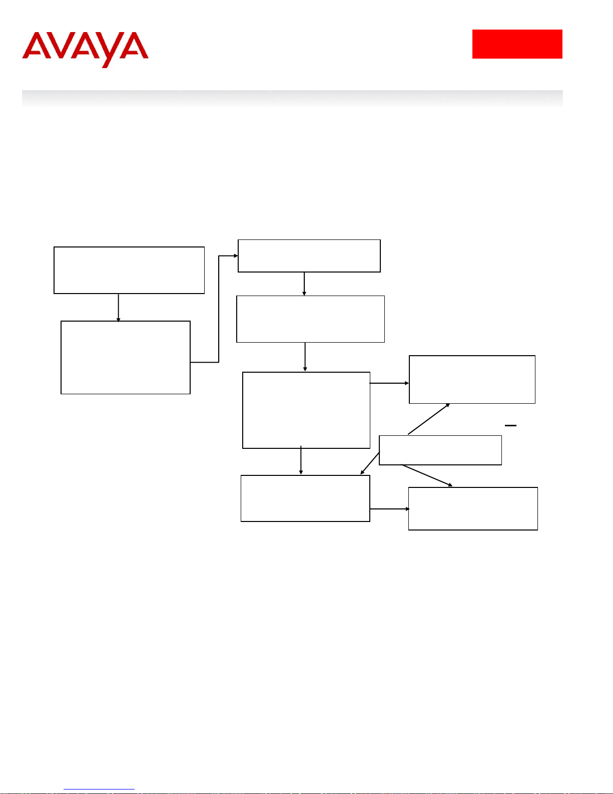
Role Combination
*Application > QoS > Devices
> Interface Configuration
Role Combination –
Interface Classes
o Trusted Ports
o Untrusted Ports
o Unrestricted
Classification
*Application > QoS > Rules
Classifier Element
o IP Classifier Element
o L2 Classifier Element
Classifier
Made up of one of the
following:
o One L2 Element
o One IP Element
o One L2 and one IP
Classifier Block
Grouping of one or more
Classifiers
Policy
Type = Classifier
*Application QoS Policy
Policy
Type = Classifier Block
*Application QoS Policy
or
Meter
*Application QoS Meter
* WEB Configuration Step
2. QoS Flow Chart
The following flowchart displays the various steps required in setting up a QoS policy. You basically now
need to create a Classifier with each Classifier made up of one IP Classifier Element, or one L2 Classifier
Element or one IP and one L2 Classifier Element. You then add the Classifier to a separate Policy on a
per port basis. Or you can group a number of Classifiers into a Classifier Block and then add the
Classifier Block to a Policy on a per port basis. The Ethernet Routing Switch 5500 supports up to 114
Classifiers per port for a total of greater than 40K Classifiers in a fully configured stack.
Filters and QOS Configuration for Ethernet Routing Switch 5500
Figure 2: QoS Flow Chart
Technical Configuration Guide

Filt
11
January 2013
avaya.com
3. Filter Functionality
3.1 Overall Classification Functionality
Classification with the Ethernet Routing Switch 5500 has some fundamental classification limitations,
imposed by hardware, that affect classification overall. The foremost limitation is related to the concept,
introduced by the latest classification hardware and the supporting data m odel, of “classification masks”.
A classification mask specifies the fields within a frame that will be used for matching purposes. The mask
itself does not specify the data to be matched but rather indicates which fields, or portions thereof, in the
various protocol headers (e.g., MAC, IPv4, IPv6 headers) will be examined during the classification
process. Currently, a maximum of 15 classification masks and 114 classifiers are available per port for
user-defined traffic classification. This effectively means that 15 or fewer unique combinations of
classification criteria (i.e., Layer 2, 3 and 4 data) can be specified per port. However, multiple data sets
can leverage the same classification mask. This means that, as long as the same protocol data fields are
being matched (e.g., IPv4 source address, IPv6 flow label, Layer 2 802.1p User Priority and VLAN Id), a
much larger number of classifiers, up to a maximum of 114 per port, can be defined containing unique
data values for matching against the fields/offsets identified by the classification mask.
3.2 Classifier Block Functionality
A user should take care when grouping a large number of individual classifiers into a classifier block.
Grouping is a quick way to inadvertently exhaust limited resources. For example, a limited number of
counters are available per interface for tracking matching/in-profile packets. Associating a block of
classifiers with a policy indicating that statistics are to be maintained could consume all counting
resources for a single interface with one policy. To avoid exhausting the number of counters available per
interface, one may select "aggregate classifier tracking" instead of "individual classifier tracking" when
creating the policy. By specifying "aggregate classifier tracking", a single counter resource is used to
track statistics for all the classifiers of that policy, rather than a single counter resource per classifier. The
obvious downside to this is the inability to track the statistics down to the granularity of each of the
classifiers associated with the policy. Individual attribute limitations include:
Individual classifier identification – a classifier set must exist prior to being referenced by the
Classifier-Block.
Individual classifier data compatibility – a classifier is eventually broken down into a bitmask
identifying fields in a packet header that are of interest and values to be matched against those
fields. Classifiers within a block must match the same protocol header fields, or portions thereof.
For example, all classifiers in a block must match against an IPv4 source host address, an IPv4
source subnet with the same number of significant bits or the Layer 2 EtherType field in a tagged
packet. A classifier matching against an IPv4 source host address and another matching against
an IPv4 destination host address may not be members of the same block as these classifiers do
not share a common classification mask. The values to be matched against may differ but the
fields being matched may not.
Referenced component consistency – all the elements that comprise a block (i.e., all classifier blocks with
the same block number) must either reference an action or a meter component or none of the elements
are permitted to reference an action or a meter. In other words, all block members must specify the same
type of information, be it action criteria, metering criteria or neither. The referenced action or metering
elements may differ across block members but all members must reference individual actions or meters
(but not actions and meters) if any do.
Filter example:
Filters and QOS Configuration for Ethernet Routing Switch 5500
Technical Configuration Guide

Filt
12
January 2013
avaya.com
a) IP Classifier #1: src IP = 10.1.1.0/24
b) IP Classifier #2: src IP = 10.20.0.0/16
c) IP Classifier #3: src IP = 172.1.1.0/24
d) IP Classifier #4: src IP = 10.22.0.0/16
e) IP Classifier #5: src IP = 10.1.2.0/24, dst IP = 192.1.1.0/24
f) IP Classifier #6: src = 10.1.10.0/24
Classifiers a, c and f can be combined to create a classifier block if you wish to filter on these addresses
on a port(s). Classifiers b and d can be combined to create a second classifier block if you wish to filter on
these addresses on a port(s).
3.3 Port Range Functionality
The Ethernet Routing Switch 5500 has the ability to specify a range of values supported by the QoS data
model for several classification components (e.g., Layer 4 source and destination port numbers, VLAN Id
values). Range support is limited to a certain extent, however, because ranges are represented as a
bitmask within the overall classification mask, and not with explicit minimum and maximum values. A
range must thus be specified by indicating which bits in the given field (e.g., Layer 4 source port) are
„ignored‟ (i.e., set to 0). Taking i nto account this limitation, the following rules are use d to determine valid
range values:
I. Minimum value: n
Maximum value: n
>> Example: min: 20 max: 20 (min = max equates to a range of 1)
II. Minimum value: 0
Maximum value: (2^n) – 1
>> Example: min: 0 max: 63 (n = 6)
III. Minimum value: even number
Maximum value: minimum port number in binary with rightmost consecutive 0‟s replaced with 1‟s
using the formula: Port Maximum = ((Port minimum + 2n) -1)) where n equal number of
consecuti ve trailing zero‟s.
>> Example: min: 128 max: 255 ((128 + 27) – 1 = 255; 128 in binary has 7 consecutive trailing
zero‟s)
Specified ranges that do not adhere to one of these three rules cannot be supported and will be
flagged as erroneous.
The following table shows some examples of valid port ranges supported on the Ethernet Routing Switch
5500.
Filters and QOS Configuration for Ethernet Routing Switch 5500
Technical Configuration Guide
Filt
13
January 2013
avaya.com
Minimum Value (must
be even number)
Maximum Value
Binary Value
0
1, 3, 7, 15, 31, 63, 127,
255, 511, 1025, 2047,
4095, 8191, 16355,
32762, or 65535
2 3 Min = 10
Max = 11
4 7 Min = 100
Max = 111
8
15
Min = 1000
Max = 1111
80
95
Min = 10100000
Max = 10111111
When source/destination port ranges or VLAN ranges are used to create the classifier,
the mask of the range must be the same for all classifiers being combined in a classifier
block.
Example:
We have the following IP elements:
qos ip-element 1 addr-type ipv4 src-ip 10.10.10.0/24 dst-ip
10.10.20.0/24 protocol 17 dst-port-min 3000 dst-port-max 3007
qos ip-element 2 addr-type ipv4 src-ip 10.10.10.0/24 dst-ip
10.10.20.0/24 protocol 17 dst-port-min 3008 dst-port-max 3071
qos ip-element 3 addr-type ipv4 src-ip 10 .10.10.0/24 dst-ip
10.10.20.0/24 protocol 17 dst-port-min 3072 dst-port-max 3135
3000 = 101110111000
3007 = 101110111111
mask is: 111
3008 = 101111000000
3071 = 101111111111
mask is: 111111
3072 = 110000000000
3135 = 110000111111
mask is: 111111
In the above example, classifiers that are formed using the second and third IP-element
with the mask of 111111 can be combined into a classifier block. The first one cannot be
part of the same classifier block.
Table 2: Example of Valid Port Ranges
Filters and QOS Configuration for Ethernet Routing Switch 5500
Technical Configuration Guide

Filt
14
January 2013
avaya.com
3.4 Policies
Packets received on an interface are matched against all policies associated with that interface.
Hence, all policies are applied to the packet.
Policy precedence – the precedence attribute is used to specify the evaluation order of policies
that apply to the same interfaces. Policies with higher precedence (i.e., a larger value) are applied
before those with lower precedence (i.e., a smaller value). Precedence values must be unique for
all policies being applied to the same interface role.
If one policy associated with the specific interface only specifies a value updating the DSCP value
while another policy associated with that same interface only specifies a value for updating the
802.1p user priority value, both of these actions occur.
If two policies on the specified interface request that the DSCP be updated but specify different
values - the value from the policy with the higher precedence will be used.
Referenced component conflicts - action or meter criteria can be specified through individual
classifier blocks. When a policy references a classifier block and members of the referenced
block identify their own action or meter criteria, action and meter data must not be specified by
the policy.
The actions applied to packets include those actions defined from user-defined policies and those
actions defined from system default policies. The user-defined actions always carry a higher
precedence than the system default actions. This means that, if user-defined policies do not
specify actions that overlap with the actions associated with system default policies (for example,
the DSCP and 802.1p update actions installed on untrusted interfaces), the lowest precedence,
default policy actions will be included in the set of actions to be applied to the identified traffic.
The following table displays the ERS 5500 default policy action with corresponding drop actions.
The drop action specifies whether a packet should be dropped, not dropped, or deferred. A drop
action of deferred-Pass specifies that a traffic flow decision will be deferred to other installed
policies.
Filters and QOS Configuration for Ethernet Routing Switch 5500
Technical Configuration Guide
Filt
15
January 2013
avaya.com
ID
Name
Drop
Update DSCP
User Priority
Drop
Precedence
1
Drop_Traffic
drop
Ignore
Ignore
highDropPrec
2
Standard_Service
Don‟t Drop
0x00
Priority 0
highDropPrec
3
Bronze_Service
Don‟t Drop
0x0a
Priority 2
lowDropPrec
4
Silver_Service
Don‟t Drop
0x12
Priority 3
lowDropPrec
5
Gold_Service
Don‟t Drop
0x1a
Priority 4
lowDropPrec
6
Platinum_Service
Don‟t Drop
0x22
Priority 5
lowDropPrec
7
Premium_Service
Don‟t Drop
0x2e
Priority 6
lowDropPrec
8
Network_Service
Don‟t Drop
0x30
Priority 7
lowDropPrec
9
Null_Service
Don‟t Drop
ignore
ignore
lowDropPrec
When setting up multiple policies using any of the default policy actions ID‟s 2 to 9 (i.e.
Standard_Service, Bronze_Service, etc) a lower precedence policy with a drop action,
(i.e. Drop_Traffic), the Drop_Traffic action will effect the higher precedence policies. The
end result is all the higher precedence policies will also be dropped. The reason for this
is each of the default actions, with the exception of Drop_Traffic, uses a drop action of
deferred-Pass. A drop action of deferred-Pass specifies that a traffic flow decision will
be deferred to other installed policies.
The valid precedence range for QoS policies is from 1 to 15. However, depending on
the application enabled, the valid precedence range can change as QoS shares
resources with other switch applications including DHCP Relay, MAC Security, IP Fix,
IGMP, EAPOL, EAP multihost (5530-24TFD only), OSPF, IP Source Guard, and ADAC.
Please use the comm and „show qos diag’ to view the mask utilization per port.
In release 4.1, FCS November 2004, the system default actions (e.g. bronze, silver,
gold, etc.) will be changed from deferred-Pass to dontDrop.
Table 3: Default Policy Drop Action
To make a policy behave somewhat similar to stop-on-match, you will have to create a new action with a
drop action of dontDrop (JDM) or disable (CLI).
Statistics accumulation support – a limited number of counters are available for tracking statistics.
Specifically, 32 counters are available per port for tracking matching (no metering specified) /inprofile (metering specified) traffic statistics. A total of 63 counters are available (per port) to track
out-of-profile statistics, with the caveat that these counters are associated with the metering
component and flows sharing the same meter on the same port use the same counter for
statistics.
Filters and QOS Configuration for Ethernet Routing Switch 5500
Technical Configuration Guide
Filt
16
January 2013
avaya.com
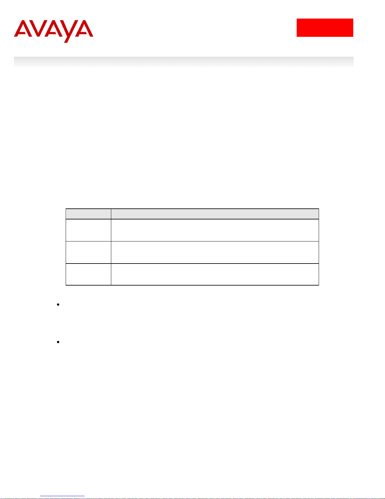
Setting
Description
Regular
1 port may use up to 16% of the buffers for a group of 12 ports.
Large
1 port may use up to 33% of the buffers for a group of 12 ports.
Maximum
1 port may use 100% of the buffers for a group of 12 ports.
Avaya recommends you use the default resource-sharing setting of regular. If you
change the setting, the resulting performance may increase for some ports, and at
times, decrease for other ports.
4. Queue Sets
Prior to software release 4.0, the Ethernet Routing Switch 5500 supported a single queue set with eight
queues, one absolute queue and seven WRR queues.
With the introduction of software release 4.0, eight different queue sets where made available. Each
queue set has different characteristics in regards to number of queues and service weights allowing the
user to select a queue set based on the user‟s particular needs. With eight queue settings and three
resource sharing options, the Ethernet Routing Switch 5500 supports a total of 24 different queues and
buffer setting combinations. Prior to making any changes to the egress queue, the buffer resource
sharing feature must be enabled.
Resource Sharing
The three (3) possible resource sharing settings in version 4.0 or greater software release are regular,
large, and maximum. These settings allow the user to change the amount of buffer which can be
allocated or shared to any port. Note that the switch must be rebooted if any changes are made.
Table 4: Ethernet Routing Switch 5500 Resource Sharing
Resource Sharing Commands
5520-24T-PWR(config)# qos agent buffer <large | maximum | regular>
The qos agent buffer <regular | large | maximum > command allows the user to specify the level
of resource sharing on the switch. This parameter is global and requires a reset to activate a
change. This command is in the CLI priv-exec mode.
5520-24T-PWR(config)# default qos agent buffer
The default qos agent buffer command sets the switches agent buffer back to a default setting of
regular. In order for this command to take affect, a reset of the switch must occur. This
command is in the CLI priv-exec mode.
Resource Sharing Recommendations
Generally speaking, smaller buffers achieve lower latency (RTT) but reduce the throughput ability which is
better for VoIP etc. and sensible jitter application.
You should use the Maximum resource sharing setting:
Filters and QOS Configuration for Ethernet Routing Switch 5500
Technical Configuration Guide
Filt
17
January 2013
avaya.com
Setting
Internal
Priority
Egress
CoS
Queue
Dequeuing
Algorithm
Weight
Regular
Memory/
# of 1518
Byte
Packets
Large
Memory/ #
of 1518
Byte
Packets
Max
Memory/ #
of 1518
Byte
Packets
8 CoS
7 1 Strict
100%
36864B
49152B
131072B
24
32
86
6
2
Weighted
Round Robin
41%
36864B
47104B
123392B
24
31
81
5 3 19%
27648B
45056B
115712B
18
29
76
4 4 13%
18432B
43008B
108032B
12
28
71
3 5 11%
18432B
39936B
97792B
12
26
64
2 6 8%
18432B
36864B
85504B
12
24
56
1 7 5%
18432B
33792B
70656B
12
22
46
0 8 3%
18432B
30720B
54272B
12
20
35
7 CoS
7 1 Strict
100%
36864B
49152B
144640B
24
32
95
6
2
Weighted
Round Robin
45%
32768B
46080B
131840B
21
30
86 5 3
21%
26624B
39936B
120064B
If you are using your 5520 for big file transfers (like backup of servers)
If you are using (the AppleTalk Filing Protocol) AFP, use large or maximum resource sharing
(AFP use a fix windows size set to 65,535K).You should use the large resource sharing setting:
If you are using your 5520 for high bandwidth application such as video.
If you are using large TCP windows for your traffic, use large resource sharing (you can also
reduce the TCP windows size on windows operating system - see Microsoft TechNet article
224829).
If you have 4 or fewer ports connected per group of 12 ports.
You should use the Regular resource sharing setting:
If you are using your 5520 in a VOIP environment.
If you have 5 or more ports connected per group of 12 ports.
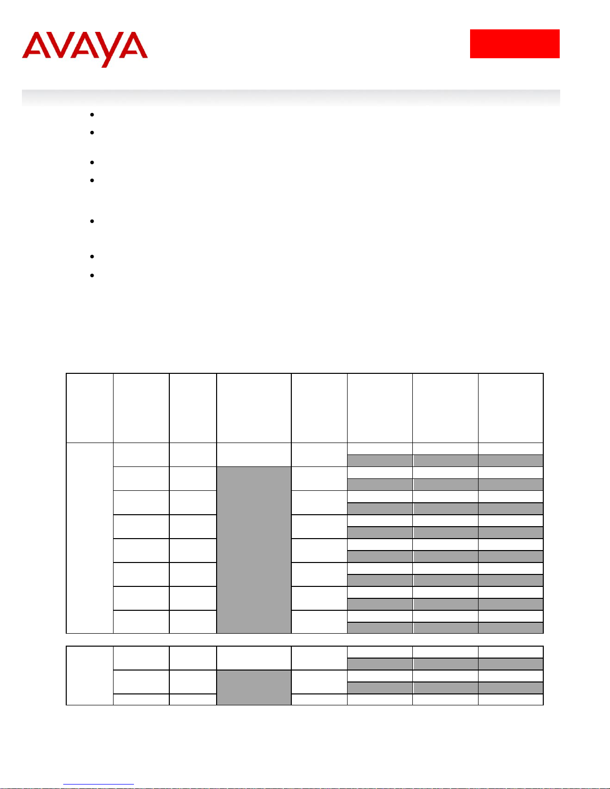
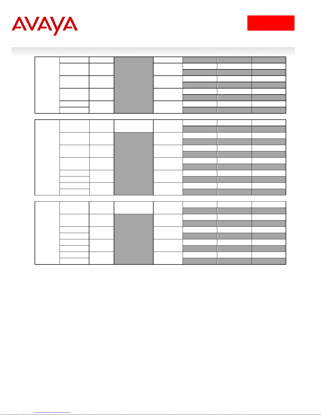
Egress CoS Queuing
The following charts describe each possible egress CoS queuing setting. The mapping of 802.1p priority
to egress CoS queue, dequeuing algorithm, and queue weight is given. Additionally, the memory and
maximum number of packets which can be buffered per egress CoS queue and resource sharing settings
is shown.
Table 5: Ethernet Routing Switch 5500 Egress CoS Queuing
Filters and QOS Configuration for Ethernet Routing Switch 5500
Technical Configuration Guide
Filt
18
January 2013
avaya.com
17
26
79
4 4 15%
19968B
33280B
109824B
13
21
72
3 5 10%
18432B
31232B
100864B
12
20
66
2 6 6%
18432B
31232B
92800B
12
20
61
1
7
3%
18432B
31232B
86400B
0
12
20
56
6 CoS
7 1 Strict
100%
36864B
51200B
163840B
24
33
107
6
2
Weighted
Round Robin
52%
33792B
49152B
151040B
22
32
99
5 3 24%
31744B
47104B
137472B
20
31
90
4 4 14%
26624B
43008B
124160B
17
28
81
3
5
7%
21504B
37376B
111360B
2
14
24
73
1
6
3%
18432B
34304B
98560B
0
12
22
64
5 CoS
7 1 Strict
100%
46080B
64000B
199680B
30
42
131
6
2
Weighted
Round Robin
58%
41984B
59904B
181760B
27
39
119
5
3
27%
35840B
53760B
158720B
4
23
35
104
3
4
11%
28160B
46080B
133120B
2
18
30
87
1
5
4%
19968B
38400B
113152B
0
13
25
74
Filters and QOS Configuration for Ethernet Routing Switch 5500
Technical Configuration Guide
Filt
19
January 2013
avaya.com
4 CoS
7
1
Strict
100%
57344B
81920B
262912B
6
37
53
173
5
2
Weighted
Round Robin
65%
51200B
74240B
209920B
4
33
48
138
3
3
26%
38912B
61440B
176640B
2
25
40
116
1
4
9%
24576B
44544B
136960B
0
16
29
90
3 CoS
7
1
Strict
100%
65536B
109568B
393316B
6
43
72
259
5
2
Weighted
Round Robin
75%
57344B
87040B
262144B
4
37
57
172
3
2
3
25%
49152B
65536B
131072B
1
32
43
86
2 CoS
7
1
Strict
100%
106496B
180224B
524288B
6
5
70
118
345
4
3
2
Weighted
Round Robin
100%
61440B
81920B
262144B
2 1 40
53
172
1 CoS
7
1
Strict
100%
131072B
262144B
786432B
6
5 4 3
86
172
518
Egress CoS Queuing CLI Commands
5520-24T-PWR(config)# show qos queue-set-assignment
The show qos queue-set-assignment command displays in the CLI the 802.1p priority to egress
CoS and QoS queue mapping for CoS setting 1-8. This command is in the CLI priv-exec mode.
5520-24T-PWR(config)# show qos queue-set
The show qos queue-set command displays the queue set configuration. The display includes
the general discipline of the queue, the percent bandwidth (Kbps), and the queues size in bytes.
This command is in the CLI priv-exec mode.
5520-24T-PWR(config)# qos agent queue set <1-8>
The qos agent queue set <1-8> command sets the egress CoS and QoS queue mode (1-8) in
which the switch will operate. This parameter is global and requires a reset to activate a change.
This command is in the CLI priv-exec mode.
5520-24T-PWR(config)# qos queue-set-assignment queue-set <1-8> 1p <0-7> queue <1-8>
Filters and QOS Configuration for Ethernet Routing Switch 5500
Technical Configuration Guide

Filt
20
January 2013
avaya.com
The qos queue-set-assignment queue-set <1-8> 1p <0-7> queue <1-8> command gives the user
the ability to specify the queue to associate an 802.1p priority. This command is in the CLI privexec mode.
5520-24T-PWR(config)# default qos agent queue-set
The default qos agent queue-set command will default the egress CoS and QoS queue set. The
default CoS/QoS queue mode is 8. This command is in the CLI priv-exec mode.
5520-24T-PWR(config)# show qos agent
The show qos agent command displays the current attributes for egress CoS and QoS queue
mode, resource sharing mode and QoS NVRAM commit delay. This command is in the CLI privexec mode.
5520-24T-PWR(config)# qos agent nvram delay
The qos agent nvram delay command will modify the maximum time in seconds to write config
data to non-volatile storage. This command is in the CLI priv-exec mode.
5520-24T-PWR(config)# qos agent reset-default
The qos agent reset-default command resets QoS to its configuration default. This command is
in the CLI priv-exec mode.
Egress Queue Recommendations
If you are running all untagged traffic and do not change default port priority settings, use setting 1 CoS.
Filters and QOS Configuration for Ethernet Routing Switch 5500
Technical Configuration Guide

Filt
21
January 2013
avaya.com
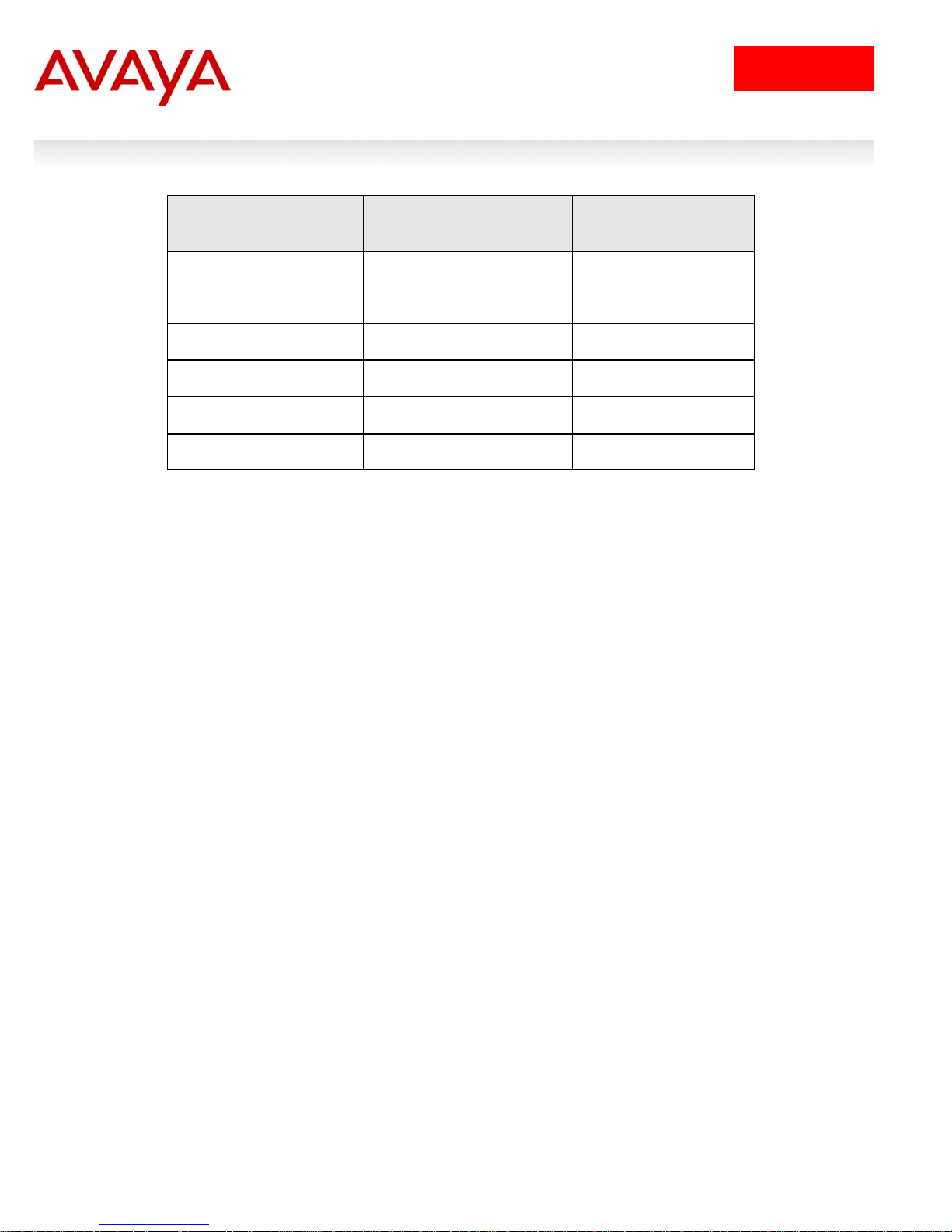
Product
Meter/Shaper Range
Granularity
Bucket Size
ERS 5510
1 Mbps to 1023 Mbps
1 Mbps
8 buckets
ERS 5520
1 Mbps to 1023 Mbps
1 Mbps
8 buckets
ERS 5530
(10M/100M,1G)
64 Kbps to 1023
Mbps
64 Kbps
8 buckets
ERS 5530 (10G)
1 Mbps to 1023 Gbps
1 Mbps
12 buckets
5. Traffic Meter and Shaping
The Ethernet Routing Switch 5500 supports both policing/metering of ingress traffic in addition to egress
port shaping. The meter and shape range is as shown in table 6 below. Please note that all QoS levels
are respected and honoured on a shaped interface.
Table 6: Meter and Shaping Range and Granularity
When configuring traffic metering or shaping, a committed rate, a maximum burst size and burst duration
is entered. The maximum burst rate and burst duration is used along with the committed rate to setup a
fixed token bucket where each token represents 1 byte. Up to eight fixed bucket sizes are supported for
all 10/100 Mbps and GigE ports. Up to twelve fixed bucket sizes are supported on the ERS 5530 only via
the 10 GigE interface. The token bucket allows a committed burst to occur up to the token bucket size.
For traffic metering, an in profile and an out of profile action is configured and is expressed as an id. You
can use one of the default actions or create a new action prior to configuring a mete r. To view the action
id‟s, please use the comm and shown below. For example, if you wish to remark the in profile traffic with a
QoS level of Bronze and drop traffic for out of profile traffic, select id 3 and 1 respectively. Please note
that you must associate the classifier to identify IP traffic since the DSCP value is being remarked.
5530-24TFD(config)# show qos action
Id Name Drop Update 802.1p Set Drop Extension Storage
DSCP Priority Precedence Type
_____ ________________ _____ ______ ____________ ___________ _________ _______
1 Drop_Traffic Yes Ignore Ignore High Drop ReadOnl
2 Standard_Service No 0x0 Priority 0 High Drop ReadOnl
3 Bronze_Service No 0xA Priority 2 Low Drop ReadOnl
4 Silver_Service No 0x12 Priority 3 Low Drop ReadOnl
5 Gold_Service No 0x1A Priority 4 Low Drop ReadOnl
6 Platinum_Service No 0x22 Priority 5 Low Drop ReadOnl
7 Premium_Service No 0x2E Priority 6 Low Drop ReadOnl
8 Network_Service No 0x30 Priority 7 Low Drop ReadOnl
9 Null_Action No Ignore Ignore Low Drop ReadOnl
55001 UntrustedClfrs1 DPass Ing 1p Ignore Low Drop Other
55002 UntrustedClfrs2 DPass 0x0 Priority 0 High Drop Other
.
Filters and QOS Configuration for Ethernet Routing Switch 5500
Technical Configuration Guide
Filt
22
January 2013
avaya.com
Bucket Size
Actual size in bytes
Interface
4K
4,096
10/100 Mbps and GigE
8K
8,192
10/100 Mbps and GigE
16K
16,384
10/100 Mbps and GigE
32K
32,768
10/100 Mbps and GigE
64K
65,536
10/100 Mbps and GigE
128K
131,072
10/100 Mbps and GigE
256K
262,144
10/100 Mbps and GigE
512K
524,288
10/100 Mbps and GigE
1024K
1,048,576
10 GigE (5530)
4096K
2,097,152
10 GigE (5530)
8192K
8,388,608
10 GigE (5530)
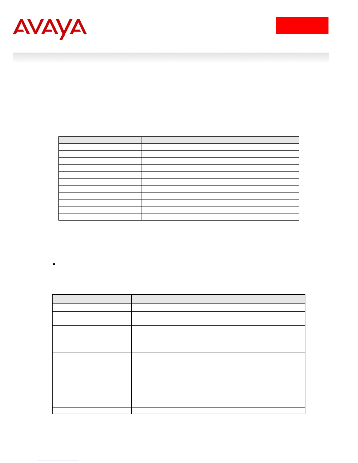
Parameter
Description
<1-55000>
Enter an integer to specify the QoS meter; range is 1 to 55000.
name <WORD>
Specify name for meter; maximum is 16 alphanumeric
characters.
committed-rate
<64-10230000>
Specifies rate that traffic must not exceed for extended periods to
be considered in-profile. Enter the rate in Kb/s for in-profile traffic
in increments of 1000 Kbits/sec; range is 64 to 10230000
Kbits/sec.
max-burst-rate
<64-4294967295>
Specifies the largest burst of traffic that can be received in a
given time for the traffic to be considered in-profile. Used in
calculating the committed burst size. Enter the burst size in Kb/s
for in-profile traffic; range is 64 to 294967295 Kbits/sec
max-burst-duration
<1-4294967295>
Specifies the amount of time that the largest burst of traffic can
be received for the traffic to be considered in -profile. Used in
calculating the committed burst size. Enter the burst duration in
ms for in-profile traffic; range is 1 to 4294967295 ms.
in-profile-action <1-55000>
Specify the in-profile action ID; range is 1 to 55000.
5.1 Actual Bucket Size
When configuring a meter or shape rate, a fixed token bucket is also configured which is derived from the
committed rate, burst rate, and burst duration configured. If a burst duration is not configured, the largest
bucket size is automatically selected which would be 512K for a 10/100 Mbps or 1 GigE port. If you wish
to use another bucket size, you must calculate the burst duration by using the actual size of the bucket Sections 5.2 and 5.3 provide examples. The following table, Table 7, shown below displays the actual
bucket size in bytes.
Table 7: Actual Bucket Size in Bytes
5.2 Policing Traffic
When configuring traffic policing, the committed rate, burst rate, and burst duration can be configured
using the following command:
5530-24TFD(config)# qos meter <1-55000> committed-rate <64-10230000 Kbits/sec> max-
burst-rate <64-4294967295 Kbits/sec> max-burst-duration <1-4294967295 Milliseconds> inprofile-action <1-55000> out-profile-action [<1-1>|<9-55000>]
QoS parameters:
Filters and QOS Configuration for Ethernet Routing Switch 5500
Technical Configuration Guide
 Loading...