

Page 1

Installing a CPU Memory
Upgrade in ASN and SN
Platforms
Part No. 112944-B Rev. A
May 1997
Page 2

4401 Great America Parkway 8 Federal Street
Santa Clara, CA 95054 Billerica, MA 01821
Copyright © 1988–1997 Bay Networks, Inc.
All rights reserved. Printed in the USA. May 1997.
The information in this document is subject to change without notice. The statements, configurations, technical data,
and recommendations in this document are believed to be accurate and reliable, but are presented without express or
implied warranty . Users must tak e full responsibility for their applications of an y products specified in this document.
The information in this document is proprietary to Bay Networks, Inc.
The software described in this document is furnished under a license agreement and may only be used in accordance
with the terms of that license. A summary of the Software License is included in this document.
Restricted Rights Legend
Use, duplication, or disclosure by the United States Government is subject to restrictions as set forth in subparagraph
(c)(1)(ii) of the Rights in Technical Data and Computer Software clause at DFARS 252.227-7013.
Notice for All Other Executive Agencies
Notwithstanding any other license agreement that may pertain to, or accompany the delivery of, this computer
software, the rights of the United States Government regarding its use, reproduction, and disclosure are as set forth in
the Commercial Computer Software-Restricted Rights clause at FAR 52.227-19.
Trademarks of Bay Networks, Inc.
ACE, AFN, AN, Bay Networks, BCN, BLN, BN, BNX, CN, FN, FRE, GAME, LN, Optivity, PPX, SynOptics,
SynOptics Communications, Wellfleet and the Wellfleet logo are registered trademarks and ANH, ASN, Bay•SIS,
BayStack, BayStream, BCNX, BLNX, EZ Install, EZ Internetwork, EZ LAN, IP AutoLearn, PathMan, PhonePlus,
Quick2Config, RouterMan, SN, SPEX, Switch Node, Bay Networks Press, the Bay Networks logo and the SynOptics
logo are trademarks of Bay Networks, Inc.
Third-Party Trademarks
All other trademarks and registered trademarks are the property of their respective owners.
Statement of Conditions
In the interest of improving internal design, operational function, and/or reliability, Bay Networks, Inc. reserves the
right to make changes to the products described in this document without notice.
Bay Networks, Inc. does not assume any liability that may occur due to the use or application of the product(s) or
circuit layout(s) described herein.
Portions of the code in this software product are Copyright © 1988, Regents of the Univ ersity of California. All rights
reserved. Redistribution and use in source and binary forms of such portions are permitted, provided that the above
copyright notice and this paragraph are duplicated in all such forms and that any documentation, advertising materials,
and other materials related to such distribution and use acknowledge that such portions of the software were
developed by the University of California, Berkeley. The name of the University may not be used to endorse or
promote products derived from such portions of the software without specific prior written permission.
SUCH PORTIONS OF THE SOFTWARE ARE PROVIDED “AS IS” AND WITHOUT ANY EXPRESS OR
IMPLIED WARRANTIES, INCLUDING, WITHOUT LIMITATION, THE IMPLIED WARRANTIES OF
MERCHANTABILITY AND FITNESS FOR A PARTICULAR PURPOSE.
In addition, the program and information contained herein are licensed only pursuant to a license agreement that
contains restrictions on use and disclosure (that may incorporate by reference certain limitations and notices imposed
by third parties).
ii
112944-B Rev. A
Page 3

Electromagnetic Emissions
Meets requirements of:
FCC Part 15, Class A
EN 55 022 (CISPR 22:1985), Class A <and Class B>
VCCI Class 1 ITE
Canada Requirements Only
Canada CS-03 Rules and Regulations
Note:
The Canadian Department of Communications label identifies certified equipment. The certification means that
the equipment meets certain telecommunications network protective operations and safety requirements. The
Department does not guarantee the equipment will operate to the user's satisfaction.
Before installing this equipment, users should ensure that it is permissible to be connected to the facilities of the local
telecommunications company. The equipment must also be installed using an acceptable method of connection. In
some cases, the company's inside wiring associated with a single line individual service may be extended by means of
a certified connector assembly (telephone extension cord). The customer should be aware that compliance with the
above conditions may not prevent the degradation of service in some situations.
Repairs to certified equipment should be made by an authorized Canadian maintenance facility designated by the
supplier. Any repairs or alterations made by the user to this equipment or equipment malfunctions, may give the
telecommunications company cause to request the user to disconnect the equipment.
Users should ensure for their own protection that the electrical ground connections of the power utility, telephone lines
and internal metallic water pipe system, if present, are connected together. This precaution may be particularly
important in rural areas.
Caution:
inspection authority, or electrician, as appropriate.
Users should not attempt to make such connections themselves, but should contact the appropriate electric
Canada CS-03 -- Règles et règlements
Note:
L’étiquette du ministère des Communications du Canada indique que l’appareillage est certifié, c’est-à-dire
qu’il respecte certaines exigences de sécurité et de fonctionnement visant les réseaux de télécommunications. Le
ministère ne garantit pas que l’appareillage fonctionnera à la satisfaction de l’utilisateur.
Avant d’installer l’appareillage, s’assurer qu’il peut être branché aux installations du service de télécommunications
local. L’appareillage doit aussi être raccordé selon des méthodes acceptées. Dans certains cas, le câblage interne du
service de télécommunications utilisé pour une ligne individuelle peut être allongé au moyen d’un connecteur certifié
(prolongateur téléphonique). Le client doit toutefois prendre note qu’une telle installation n’assure pas un service
parfait en tout temps.
Les réparations de l’appareillage certifié devraient être confiées à un service d’entretien canadien désigné par le
fournisseur. En cas de réparation ou de modification effectuées par l’utilisateur ou de mauvais fonctionnement de
l’appareillage, le service de télécommunications peut demander le débranchement de l’appareillage.
Pour leur propre sécurité, les utilisateurs devraient s’assurer que les mises à la terre des lignes de distribution
d’électricité, des lignes téléphoniques et de la tuyauterie métallique interne sont raccordées ensemble. Cette mesure de
sécurité est particulièrement importante en milieu rural.
Attention:
aux pouvoirs de réglementation en cause ou à un électricien, selon le cas.
112944-B Rev. A
Les utilisateurs ne doivent pas procéder à ces raccordements eux-mêmes mais doivent plutôt faire appel
iii
Page 4

Canada Requirements Only
(continued)
D. O. C. Explanatory Notes: Equipment Attachment Limitations
The Canadian Department of Communications label identifies certified equipment. This certification meets certain
telecommunication network protective, operational and safety requirements. The department does not guarantee the
equipment will operate to the users satisfaction.
Before installing the equipment, users should ensure that it is permissible to be connected to the facilities of the local
telecommunications company. The equipment must also be installed using an acceptable method of connection. In
some cases, the company’s inside wiring associated with a single line individual service may be extended by means of
a certified connector assembly (telephone extension cord). The customer should be aware that compliance with the
above condition may not prevent degradation of service in some situations.
Repairs to certified equipment should be made by an authorized Canadian maintenance facility designated by the
supplier. Any repairs or alterations made by the user to this equipment, or equipment malfunctions, may give the
telecommunications company cause to request the user to disconnect the equipment.
Users should ensure for their own protection that the electrical ground connections of the power utility, telephone lines
and internal metallic water pipe system, if present, are connected together. This precaution may be particularly
important in rural areas.
Caution:
inspection authority, or electrician, as appropriate.
Users should not attempt to make such connections themselves, but should contact the appropriate electrical
Notes explicatives du ministère des Communications: limites visant les accessoires
L’étiquette du ministère des Communications du Canada indique que l’appareillage est certifié, c’est-à-dire qu’il
respecte certaines exigences de sécurité et de fonctionnement visant les réseaux de télécommunications. Le ministère
ne garantit pas que l’appareillage fonctionnera à la satisfaction de l’utilisateur.
Avant d’installer l’appareillage, s’assurer qu’il peut être branché aux installations du service de télécommunications
local. L’appareillage doit aussi être raccordé selon des méthodes acceptées. Dans certains cas, le câblage interne du
service de télécommunications utilisé pour une ligne individuelle peut être allongé au moyen d’un connecteur certifié
(prolongateur téléphonique). Le client doit toutefois prendre note qu’une telle installation n’assure pas un service
parfait en tout temps.
Les réparations de l’appareillage certifié devraient être confiées à un service d’entretien canadien désigné par le
fournisseur. En cas de réparation ou de modification effectuées par l’utilisateur ou de mauvais fonctionnement de
l’appareillage, le service de télécommunications peut demander le débranchement de l’appareillage.
Pour leur propre sécurité, les utilisateurs devraient s’assurer que les mises à la terre des lignes de distribution
d’électricité, des lignes téléphoniques et de la tuyauterie métallique interne sont raccordées ensemble. Cette mesure de
sécurité est particulièrement importante en milieu rural.
Attention:
aux pouvoirs de réglementation en cause ou à un électricien, selon le cas.
Les utilisateurs ne doivent pas procéder à ces raccordements eux-mêmes mais doivent plutôt faire appel
iv
112944-B Rev. A
Page 5

Canada Requirements Only
(continued)
Canadian Department of Communications Radio Interference Regulations
This digital apparatus (Access Feeder Node, Access Link Node, Access Node, Access Stack Node, Backbone
Concentrator Node, Backbone Concentrator Node Switch, Backbone Link Node, Backbone Link Node Switch,
Concentrator Node, Feeder Node, Link Node, Switch Node) does not exceed the Class A limits for radio-noise
emissions from digital apparatus as set out in the Radio Interference Regulations of the Canadian Department of
Communications.
Règlement sur le brouillage radioélectrique du ministère des Communications
Cet appareil numérique (Access Feeder Node, Access Link Node, Access Node, Access Stack Node, Backbone
Concentrator Node, Backbone Concentrator Node Switch, Backbone Link Node, Backbone Link Node Switch,
Concentrator Node, Feeder Node, Link Node, Switch Node) respecte les limites de bruits radioélectriques visant les
appareils numériques de classe A prescrites dans le Règlement sur le brouillage radioélectrique du ministère des
Communications du Canada.
112944-B Rev. A
v
Page 6

Bay Networks Software License
This is Bay Networks basic license document. In the absence of a
Note:
software license agreement specifying varying terms, this license -- or the
license included with the particular product -- shall govern licensee’s use of
Bay Networks software.
This Software License shall govern the licensing of all software provided to licensee by Bay Networks (“Software”).
Bay Networks will provide licensee with Software in machine-readable form and related documentation
(“Documentation”). The Software provided under this license is pr oprietary to Bay Networks and to third parties from
whom Bay Networks has acquired license rights. Bay Networks will not grant any Software license whatsoev er , either
explicitly or implicitly, except by acceptance of an order for either Software or for a Bay Networks product
(“Equipment”) that is packaged with Software. Each such license is subject to the following restrictions:
1. Upon delivery of the Software, Bay Networks grants to licensee a personal, nontransferable, none xclusiv e license
to use the Software with the Equipment with which or for which it was originally acquired, including use at any
of licensee’s facilities to which the Equipment may be transferred, for the useful life of the Equipment unless
earlier terminated by default or cancellation. Use of the Software shall be limited to such Equipment and to such
facility . Software which is licensed for use on hardware not offered by Bay Networks is not subject to restricted
use on any Equipment, however, unless otherwise specified on the Documentation, each licensed copy of such
Software may only be installed on one hardware item at any time.
2. Licensee may use the Software with backup Equipment only if the Equipment with which or for which it was
acquired is inoperative.
3. Licensee may make a single copy of the Software (but not firmware) for safekeeping (archives) or backup
purposes.
4. Licensee may modify Software (but not firmware), or combine it with other software, subject to the provision
that those portions of the resulting software which incorporate Software are subject to the restrictions of this
license. Licensee shall not make the resulting software available for use by any third party.
5. Neither title nor ownership to Software passes to licensee.
6. Licensee shall not provide, or otherwise make available, any Software, in whole or in part, in any form, to any
third party. Third parties do not include consultants, subcontractors, or agents of licensee who have licensee’s
permission to use the Software at licensee’s facility, and who have agreed in writing to use the Software only in
accordance with the restrictions of this license.
7. Third-party owners from whom Bay Networks has acquired license rights to software that is incorporated into
Bay Networks products shall have the right to enforce the provisions of this license against licensee.
8. Licensee shall not remove or obscure any copyright, patent, trademark, trade secret, or similar intellectual
property or restricted rights notice within or affixed to any Software and shall reproduce and affix such notice on
any backup copy of Software or copies of software resulting from modification or combination performed by
licensee as permitted by this license.
vi
112944-B Rev. A
Page 7

Bay Networks Software License
9. Licensee shall not reverse assemble, reverse compile, or in any way reverse engineer the Software. [Note: For
licensees in the European Community, the Softw are Directiv e dated 14 May 1991 (as may be amended from time
to time) shall apply for interoperability purposes. Licensee must notify Bay Networks in writing of any such
intended examination of the Software and Bay Networks may provide review and assistance.]
10. Notwithstanding any foregoing terms to the contrary, if licensee licenses the Bay Networks product “Site
Manager,” licensee may duplicate and install the Site Manager product as specified in the Documentation. This
right is granted solely as necessary for use of Site Manager on hardware installed with licensee’s network.
11. This license will automatically terminate upon improper handling of Software, such as by disclosure, or Bay
Networks may terminate this license by written notice to licensee if licensee fails to comply with any of the
material provisions of this license and fails to cure such failure within thirty (30) days after the receipt of written
notice from Bay Networks. Upon termination of this license, licensee shall discontinue all use of the Software
and return the Software and Documentation, including all copies, to Bay Networks.
12. Licensee’s obligations under this license shall survive expiration or termination of this license.
(continued)
112944-B Rev. A
vii
Page 8

Page 9

Contents
About This Guide
Conventions .....................................................................................................................xvi
Acronyms .........................................................................................................................xvi
Ordering Bay Networks Publications ...............................................................................xvi
Bay Networks Customer Service ....................................................................................xvii
How to Get Help .............................................................................................................xvii
For More Information .....................................................................................................xviii
Chapter 1
Installing a CPU Memory Upgrade in the ASN
Reviewing the SIMM Types .............................................................................................1-1
Attaching the Antistatic Wrist Strap ................................................................................1-2
Removing the ASN Component Tray ..............................................................................1-3
Removing DRAM SIMMs ................................................................................................1-5
Installing DRAM SIMMs ..................................................................................................1-7
Removing the Tag SIMM ................................................................................................1-8
Installing the Tag SIMM ................................................................................................1-11
Labeling the ASN ..........................................................................................................1-12
Replacing the ASN Component Tray ............................................................................1-13
Chapter 2
Installing a CPU Memory Upgrade in the SN
Reviewing the SIMM Types .............................................................................................2-1
Attaching the Antistatic Wrist Strap ................................................................................2-2
Removing the Switch Node CPU Module .......................................................................2-3
Removing DRAM SIMMs ................................................................................................2-5
Installing DRAM SIMMs ..................................................................................................2-7
Removing the Tag SIMM ................................................................................................2-8
Installing the Tag SIMM ..................................................................................................2-9
Labeling the Switch Node .............................................................................................2-10
112944-B Rev. A
ix
Page 10

Replacing the Switch Node CPU Module .....................................................................2-12
x
112944-B Rev. A
Page 11

Figures
Figure 1-1. Removing the ASN Component Tray .......................................................1-4
Figure 1-2. Locating the DRAM SIMMs ......................................................................1-5
Figure 1-3. Releasing the DRAM SIMM .....................................................................1-6
Figure 1-4. Orientation of DRAM SIMM .....................................................................1-7
Figure 1-5. Installing the DRAM SIMM .......................................................................1-8
Figure 1-6. Locating the Tag SIMM ............................................................................1-9
Figure 1-7. Releasing the Tag SIMM ........................................................................1-10
Figure 1-8. Installing the Tag SIMM ..........................................................................1-11
Figure 1-9. Rear Panel Labels on the ASN ..............................................................1-12
Figure 1-10. Label Locations on ASN CPU ................................................................1-13
Figure 2-1. Removing the Switch Node CPU Module ................................................2-4
Figure 2-2. Locating the DRAM SIMMs ......................................................................2-5
Figure 2-3. Releasing the DRAM SIMM .....................................................................2-6
Figure 2-4. Orientation of DRAM SIMM .....................................................................2-7
Figure 2-5. Installing the DRAM SIMM .......................................................................2-7
Figure 2-6. Locating the Tag SIMM ............................................................................2-8
Figure 2-7. Releasing the Tag SIMM ..........................................................................2-9
Figure 2-8. Installing the Tag SIMM ..........................................................................2-10
Figure 2-9. Part Number Label on the SN CPU .......................................................2-11
Figure 2-10. Replacing the Switch Node CPU Module ..............................................2-12
112944-B Rev. A
xi
Page 12

Page 13

Tables
Table 1-1. DRAM Configurations in the ASN ............................................................1-2
Table 1-2. Tag SIMM Requirements .........................................................................1-2
Table 2-1. DRAM Configurations in the SN ..............................................................2-2
Table 2-2. Tag SIMM Requirements .........................................................................2-2
112944-B Rev. A
xiii
Page 14

Page 15

About This Guide
This guide describes how to upgrade memory in an Access Stack Node (ASN™)
or Switch Node™ (SN™) platform. Chapter 1 describes the upgrade procedure
for the ASN; Chapter 2 describes the upgrade procedure for the SN.
The kit contents are similar whether you are upgrading the memory in an ASN or
SN. Check the shipment contents, referring to the table.
Memory Upgrade Options and Shipment Contents
DRAM Upgrade Upgrade Kit Kit Contains
112944-B Rev. A
8 MB Order No. AF0011003
(ASN only)
16 MB Order No. AF0011004
(ASN 4-MB to 16-MB
upgrade only; SN
16-MB memory
replacement)
16 MB Order No. 50027
(ASN 8-MB to 16-MB
upgrade only; no Tag
SIMM required)
32 MB Order No. AF0011005
(ASN and SN)
2 DRAM SIMMs
1 Tag SIMM
2 8-MB UPGRD labels
2 DRAM SIMMs
1 Tag SIMM
2 16-MB UPGRD labels
2 DRAM SIMMS
2 16-MB UPGRD labels
2 DRAM SIMMs
1 Tag SIMM
2 32-MB UPGRD labels
If any parts are damaged or missing, contact the Bay Networks Technical Support
Center in your area. (Refer to “How to Get Help,” later in this section.)
xv
Page 16

Installing a CPU Memory Upgrade in ASN and SN Platforms
Conventions
italic text
quotation marks (“ ”) Indicate the title of a chapter or section within a book.
Indicates variable values in command syntax
descriptions, new terms, file and directory names, and
book titles.
Acronyms
ASN Access Stack Node
DRAM dynamic random access memory
SIMM single inline memory module
SN Switch Node
Ordering Bay Networks Publications
To purchase additional copies of this document or other Bay Networks
publications, order by part number from Bay Networks Press™ at the following
numbers:
• Phone -- U.S./Canada: 1-888-422-9773
• Phone -- International: 1-510-490-4752
xvi
• FAX -- U.S./Canada and International: 1-510-498-2609
112944-B Rev. A
Page 17

Bay Networks Customer Service
You can purchase a support contract from your Bay Networks distributor or
authorized reseller, or directly from Bay Networks Services. For information
about, or to purchase a Bay Networks service contract, either call your local Bay
Networks field sales office or one of the following numbers:
Region Telephone number Fax number
About This Guide
United States and
Canada
Europe 33-4-92-96-69-66 33-4-92-96-69-96
Asia/Pacific 61-2-9927-8888 61-2-9927-8899
Latin America 561-988-7661 561-988-7550
How to Get Help
If you purchased a service contract for your Bay Networks product from a
distributor or authorized reseller, contact the technical support staff for that
distributor or reseller for assistance.
If you purchased a Bay Networks service program, call one of the following Bay
Networks Technical Support Centers:
Technical Support Center Telephone number Fax number
Billerica, MA 1-800-2LANWAN 508-670-8765
Santa Clara, CA 1-800-2LANWAN 408-495-1188
Valbonne, France 33-4-92-96-69-68 33-4-92-96-69-98
Sydney, Australia 61-2-9927-8800 61-2-9927-8811
Tokyo, Japan 81-3-5402-0180 81-3-5402-0173
1-800-2LANWAN; then enter Express
Routing Code (ERC) 290, when prompted,
to purchase or renew a service contract
1-508-916-8880 (direct)
1-508-670-8766
112944-B Rev. A
xvii
Page 18

Installing a CPU Memory Upgrade in ASN and SN Platforms
For More Information
For information about Bay Networks and its products, visit the Bay Networks
World Wide Web (WWW) site at http://www.baynetworks.com. To learn more
about Bay Networks Customer Service, select Customer Service on the opening
web page.
xviii
112944-B Rev. A
Page 19

Chapter 1
Installing a CPU Memory Upgrade in the ASN
This chapter describes how to install a CPU memory upgrade in a Bay Networks®
Access Stack Node (ASN). After you review the ASN SIMM types and attach the
antistatic wrist strap, you will need a Phillips screwdriver to complete the
following steps:
1.
Removing the ASN component tray
2.
Removing DRAM SIMMs
Installing DRAM SIMMs
3.
4.
Removing the Tag SIMM
5.
Installing the Tag SIMM
6.
Labeling the ASN
7.
Replacing the ASN component tray
Danger:
permitted to install or replace components in an ASN.
Due to high-energy hazards, only qualified service personnel are
Reviewing the SIMM Types
The ASN uses SIMMs to provide
• Dynamic random access memory (DRAM).
• Tag memory, which adds a protection tag to individual memory locations. For
example, a memory location might be tagged with write protection.
112944-B Rev. A
1-1
Page 20

Installing a CPU Memory Upgrade in ASN and SN Platforms
The ASN supports configurations of 8, 16, and 32 MB of DRAM. T
able 1-1 shows
the DRAM SIMM requirements for each configuration.
Table 1-1. DRAM Configurations in the ASN
Number
Configuration SIMM Capacity
8 MB 1 MB by 36 2
16 MB 2 MB by 36 2
32 MB 4 MB by 36 2
of SIMMs
The capacity of the SIMM you use for Tag memory depends on the DRAM
configuration. T
able 1-2 shows the Tag SIMM requirements for each
configuration.
Table 1-2. Tag SIMM Requirements
DRAM Configuration Tag SIMM Capacity
8 or 16 MB 1 MB by 8
32 MB 4 MB by 8
If you upgrade the DRAM, be sure to use the appropriate Tag SIMM.
Note:
Order No. 50027 does not require a Tag SIMM replacement.
Attaching the Antistatic Wrist Strap
You must wear an antistatic wrist strap whenever you remove, install, or handle a
SIMM.
Caution:
in this section to protect your equipment from damage.
1-2
Electrostatic discharge can damage hardware. Follow the procedure
112944-B Rev. A
Page 21

Installing a CPU Memory Upgrade in the ASN
To attach the antistatic wrist strap:
1.
Remove the strap, alligator clip, and cable from the package.
2.
Attach (snap) the snap end of the cable to the wrist strap.
3.
Place the strap around your wrist, and adjust the strap to ensur e that the
metal buckle inside the strap touches your skin.
4.
Plug the jack at the other end of the cable into the opening on the
alligator clip.
5.
Attach the alligator clip to any unpainted metal surface on the
component tray.
Removing the ASN Component Tray
Before you can upgrade memory in the ASN, you must remove the component
tray from the ASN chassis. To remove the ASN component tray:
1.
Turn off the ASN, and detach all cables from the back panel.
2.
Using a Phillips screwdriver, loosen the two captive screws that fasten the
tray to the chassis (F
igure 1-1).
112944-B Rev. A
3.
Pull the two captive screws and gently slide the tray out of the chassis.
Make sure to hold the sides and bottom of the tray to support it; try to keep the
tray level as you slide it out.
Place the tray on a sturdy work surface.
4.
Caution:
Do not touch any components or modules in the ASN until you ha ve
attached the antistatic wrist strap. Refer to the section “ Attaching the Antistatic
Wrist Strap.”
The net module ports are exposed at the back of the component tray. To perform
maintenance tasks on the ASN components, face the back of the tray.
1-3
Page 22

Installing a CPU Memory Upgrade in ASN and SN Platforms
Phillips
screwdriver
Captive
thumbscrews
1-4
Component tray
ASN0031A
Figure 1-1. Removing the ASN Component Tray
112944-B Rev. A
Page 23

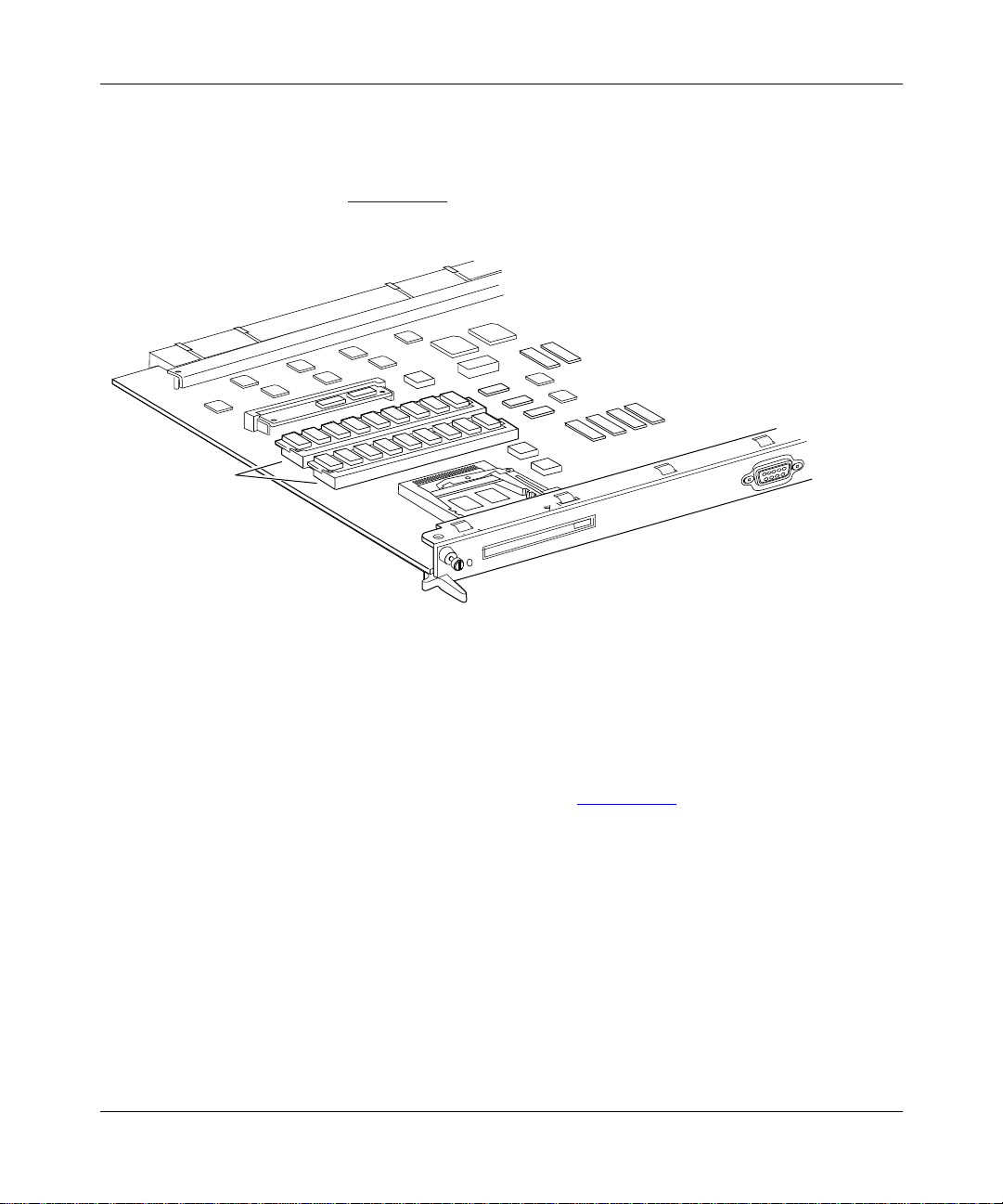
Removing DRAM SIMMs
You may need to remove DRAM SIMMs if you are upgrading the ASN memory
configuration (F
the tray. (Remember, the back of the tray is where the net module ports are
exposed.)
igure 1-2). You must first r emov e the SIMM closest to the front of
Installing a CPU Memory Upgrade in the ASN
112944-B Rev. A
DRAM SIMMs
ASN0032A
Figure 1-2. Locating the DRAM SIMMs
1-5
Page 24

Installing a CPU Memory Upgrade in ASN and SN Platforms
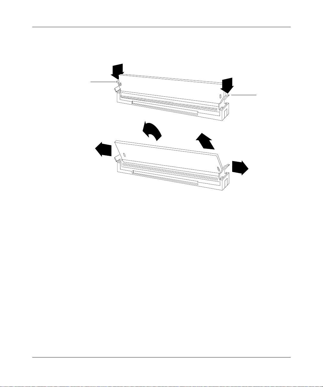
To remove a DRAM SIMM:
1.
Press down the locking tab on each side of the SIMM to release it from
the connector.
The SIMM tilts back at a slight angle toward the front of the tray (F
Locking tabs
Locking tabs
igure 1-3).
Locking tabs
1-6
Figure 1-3. Releasing the DRAM SIMM
Grasp the top corners of the SIMM and pull it up and out of the
2.
connector.
ASN0033A
112944-B Rev. A
Page 25

Installing DRAM SIMMs
When you install DRAM SIMMs, make sure that the SIMMs are the same size.
For example, you can install two 2-MB by 36 SIMMs for a 16-MB configuration;
howev er, do not install one 1-MB by 36 and one 2-MB by 36 SIMM.
Also, make sure that you are using the correct capacity Tag SIMM for your
DRAM configuration (refer to T
You must first install the SIMM closest to the back of the component tray.
To install a DRAM SIMM:
1. Grasp the SIMM by the top corners, and place it into the connector at a
slight angle.
Installing a CPU Memory Upgrade in the ASN
able 1-2).
The SIMM is keyed to fit in the connector only one way (F
igure 1-4).
Notch
ASN0034A
Figure 1-4. Orientation of DRAM SIMM
Push the SIMM toward the back of the tray until the locking tabs snap
2.
into place (F
igure 1-5).
112944-B Rev. A 1-7
Page 26

Installing a CPU Memory Upgrade in ASN and SN Platforms
Figure 1-5. Installing the DRAM SIMM
Removing the Tag SIMM
ASN0035A
You need to replace the Tag SIMM (Figure 1-6) if you are upgrading the ASN
DRAM configuration to 32 MB. T
able 1-2, shown earlier, lists the Tag SIMM
requirements for the different DRAM configurations.
Note: You do not need to replace the Tag SIMM if you are upgrading the
DRAM configuration to 8 MB or 16 MB.
To remove the Tag SIMM:
1. Attach the antistatic wrist strap and remove the component tray, as
described earlier in this chapter.
1-8 112944-B Rev. A
Page 27

Installing a CPU Memory Upgrade in the ASN
Tag SIMM
ASN0036A
Figure 1-6. Locating the Tag SIMM
Press down the locking tab on each side of the SIMM to release it from
2.
the connector (F
112944-B Rev. A 1-9
igure 1-7).
Page 28
Installing a CPU Memory Upgrade in ASN and SN Platforms
Locking tab
Locking tab
ASN0037A
Figure 1-7. Releasing the Tag SIMM
Grasp the top corners of the SIMM and gently pull it toward you at a
3.
slight angle. The SIMM naturally positions itself at an angle as you pull
it.
4. Lift the SIMM out of the connector.
1-10 112944-B Rev. A
Page 29

Installing the Tag SIMM
Before you perform this procedure, be sure to attach the antistatic wrist strap, as
described earlier in this chapter.
To install the Tag SIMM:
1. Grasp the SIMM by the top corners and place it into the connector at a
slight angle (F
The SIMM is keyed to fit in the connector only one way.
Notch
Installing a CPU Memory Upgrade in the ASN
igure 1-8).
ASN0038A
Figure 1-8. Installing the Tag SIMM
Push the SIMM away from you until the locking tabs snap into place.
2.
112944-B Rev. A 1-11
Page 30

Installing a CPU Memory Upgrade in ASN and SN Platforms
Labeling the ASN
After you perform the DRAM SIMM upgrade, label the ASN rear panel and the
ASN CPU with the Memory Size labels provided in the kit. Affixing the new
labels is important because future repairs and upgrades will require that you
correctly identify the memory configuration of your ASN.
To label your ASN:
1. Identify the existing Order Number label by looking at the rear panel of
Rear panel
Order Number
label
the ASN (F
Memory Size label
SERIAL • ASN21Ø49
PART • 127844 REV 22
MODEL • 3ØØØ1
igure 1-9).
110
SD
2
2
PHY
B
Y
B
TX
P
A
S
S
S
XMT/RCV
PHY
A
P
FDDI-MM
34003
SD
TX
F
ETHERNET
34000
1
F
ASN0076A
Figure 1-9. Rear Panel Labels on the ASN
Apply the Memory Size label at the end of the Order Number label,
2.
making sure that you do not cover any portion of the bar code (r
efer to
Figure 1-9).
3. Find the Part Number label on the ASN CPU (Figure 1-10).
The Part Number label will read 110341-xx (ASN), 107072-xx (ASN), or
112842-xx (ASN2).
1-12 112944-B Rev. A
Page 31

Installing a CPU Memory Upgrade in the ASN
Apply the other Memory Size label to the CPU as follows:
4.
• On an ASN CPU (110341-xx or 107072-xx), apply the label to the right of
the CPU Part Number label (F
igure 1-10).
• On an ASN2 CPU (112842-xx), apply the label below the CPU Part
Number label, near the edge of the CPU (F
Memory Size
label location
CPU Part
Number label
igure 1-10).
CPU Serial
Number label
Memory Size label
location on ASN2 CPU
ASN0077A
Figure 1-10. Label Locations on ASN CPU
Replacing the ASN Component Tray
To replace the ASN component tray:
1. Gently slide the tray into the chassis.
2. Using a Phillips screwdriver, tighten the two captive screws that fasten the tray to
the chassis (r
3. Reattach the cables to the proper connectors on the back panel.
4. Turn on the ASN.
112944-B Rev. A 1-13
efer to Figure 1-1).
Page 32

Page 33

Chapter 2
Installing a CPU Memory Upgrade in the SN
This chapter describes how to install a CPU memory upgrade in a Bay Networks
Switch Node (SN). After you review the SN SIMM types and attach the antistatic
wrist strap, you will need a flat-tip screwdriver to complete the following steps:
1. Removing the SN CPU module
2. Removing DRAM SIMMs
3. Installing DRAM SIMMs
4. Removing the Tag SIMM
5. Installing the Tag SIMM
6. Labeling the SN
7. Replacing the SN CPU module
Reviewing the SIMM Types
The SN uses SIMMs to provide the following:
• Dynamic random access memory (DRAM).
• Tag memory, which adds a protection tag to individual memory locations. For
example, a memory location might be tagged with write protection.
112944-B Rev. A 2-1
Page 34

Installing a CPU Memory Upgrade in ASN and SN Platforms
The SN supports configurations of 16 and 32 MB of DRAM. Table 2-1 shows the
DRAM SIMM requirements for each configuration.
Table 2-1. DRAM Configurations in the SN
Number
Configuration SIMM Capacity
16 MB 2 MB by 36 2
32 MB 4 MB by 36 2
of SIMMs
The capacity of the SIMM you use for Tag memory depends on the DRAM
configuration. T
able 2-2 shows the Tag SIMM requirements for each
configuration.
Table 2-2. Tag SIMM Requirements
DRAM Configuration Tag SIMM Capacity
16 MB 1 MB by 8
32 MB 4 MB by 8
If you upgrade the DRAM, be sure to use the appropriate Tag SIMM.
Attaching the Antistatic Wrist Strap
You must wear an antistatic wrist strap whenever you remove, install, or handle a
SIMM.
Caution: Electrostatic discharge can damage hardware. Follow the procedure
in this section to protect your equipment from damage.
To attach the antistatic wrist strap:
1. Remove the strap, alligator clip, and cable from the package.
2. Attach (snap) the snap end of the cable to the wrist strap.
3. Place the strap around your wrist, and adjust the strap to ensur e that the
metal buckle inside the strap touches your skin.
2-2 112944-B Rev. A
Page 35

Installing a CPU Memory Upgrade in the SN
Plug the jack at the other end of the cable into the opening on the
4.
alligator clip.
5. Attach the alligator clip to any unpainted metal surface on the chassis.
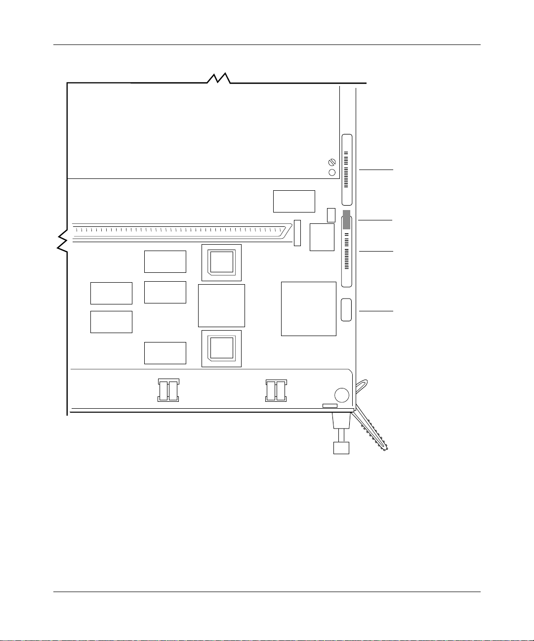
Removing the Switch Node CPU Module
To remove the SN CPU module:
1. Turn off the Switch Node.
2. Disconnect any modem and console cables that are attached to the CPU
module.
3. Remove the flash memory card from the PCMCIA slot by pressing the
eject button to the right of the slot (F
4. Using a flat-tip screwdriver, loosen the captive retaining screws.
5. Press the module levers down so that they are parallel to the front of the
module.
You will feel the module disconnect from the Switch Node midplane.
igure 2-1).
6. Pull the captive retaining screws toward you to pull the module partially
out of the chassis. Grasp the module by its edges to remove it from the
chassis.
7. Place the module on an antistatic work surface.
Caution: Do not touch any components or modules in the Switch Node until
you have attached the antistatic wrist strap. Refer to the section “Attaching the
Antistatic Wrist Strap.”
112944-B Rev. A 2-3
Page 36

Installing a CPU Memory Upgrade in ASN and SN Platforms
Captive
screw
Flash memory card
Console/ Diagnostics Console/ Modem
1
2
4
PCMCIA
Module lever
3
2
1
Figure 2-1. Removing the Switch Node CPU Module
10BASE-T
Reset
CPU 060
ATM OC-3
100 BASE-TX
Module lever
FX0021A
2-4 112944-B Rev. A
Page 37
Removing DRAM SIMMs
You may need to remove DRAM SIMMs if you are upgrading the SN memory
configuration (F
igure 2-2).
Installing a CPU Memory Upgrade in the SN
DRAM
SIMMs
Figure 2-2. Locating the DRAM SIMMs
To remove a DRAM SIMM:
1. Press down the locking tab on each side of the SIMM.
The SIMM tilts back at a slight angle (F
Console/ Modem
PCMCIA
FX0027A
igure 2-3).
112944-B Rev. A 2-5
Page 38

Installing a CPU Memory Upgrade in ASN and SN Platforms
FX0028A
Figure 2-3. Releasing the DRAM SIMM
Grasp the top corners of the SIMM and pull it up and out of the
2.
connector.
2-6 112944-B Rev. A
Page 39

Installing DRAM SIMMs
When you install DRAM SIMMs, make sure that the SIMMs are the same size.
For example, you can install two 2-MB by 36 SIMMs for a 16-MB configuration;
howev er, do not install one 1-MB by 36 and one 2-MB by 36 SIMM.
Also, make sure that you are using the correct capacity Tag SIMM for your
DRAM configuration (refer to T
You must first install the SIMM closest to the back of the CPU.
To install a DRAM SIMM:
1. Grasp the SIMM by the top corners, and place it into the connector at a
slight angle.
Installing a CPU Memory Upgrade in the SN
able 2-2).
The SIMM is keyed to fit in the connector only one way (F
Notch
FX0029A
Figure 2-4. Orientation of DRAM SIMM
Push down on the SIMM until the locking tabs snap into place
2.
igure 2-5).
(F
igure 2-4).
FX0030A
Figure 2-5. Installing the DRAM SIMM
112944-B Rev. A 2-7
Page 40

Installing a CPU Memory Upgrade in ASN and SN Platforms
Removing the Tag SIMM
You need to replace the Tag SIMM (Figure 2-6) if you are upgrading the SN
DRAM configuration to 32 MB. T
requirements for the different DRAM configurations.
To remove the Tag SIMM:
1. Attach the antistatic wrist strap and remove the CPU, as described
earlier in this chapter.
able 2-2, shown earlier, lists the Tag SIMM
Tag
SIMM
Figure 2-6. Locating the Tag SIMM
Spread the locking tabs on the sides of the SIMM to release it from the
2.
connector (F
igure 2-7).
Console/ Modem
PCMCIA
FX0031A
2-8 112944-B Rev. A
Page 41

Installing a CPU Memory Upgrade in the SN
Locking tab
Locking tab
FX0032A
Figure 2-7. Releasing the Tag SIMM
3. Lift the SIMM out of the connector.
Installing the Tag SIMM
Before you perform this procedure, be sure to attach the antistatic wrist strap, as
described earlier in this chapter.
To install the Tag SIMM:
1. Grasp the SIMM by the top corners and place it into the connector at a
slight angle (F
The SIMM is keyed to fit in the connector only one way.
112944-B Rev. A 2-9
igure 2-8).
Page 42

Installing a CPU Memory Upgrade in ASN and SN Platforms
FX0033A
Figure 2-8. Installing the Tag SIMM
Push down on the SIMM until the locking tabs snap into place.
2.
Labeling the Switch Node
After you perform the DRAM SIMM upgrade, label the SN CPU with a new
Memory Size label. Af fixing the new label is important because future repairs and
upgrades will require that you correctly identify the current memory configuration
of your SN.
To label your SN:
1. Find the CPU Part Number label on the SN CPU (Figure 2-9).
The CPU Part Number label will read 114252-16 or 114252-32.
2. Apply the Memory Size label to the end of the CPU Part Number label,
making sure that you do not cover any portion of the bar code.
The Memory Size label should be next to the component reference designator
C36 (F
2-10 112944-B Rev. A
igure 2-9).
Page 43
Installing a CPU Memory Upgrade in the SN
Serial Number
label
C36
Memory Size
label
CPU Part
Number label
Figure 2-9. Part Number Label on the SN CPU
CPU revision number
FX0065A
112944-B Rev. A 2-11
Page 44

Installing a CPU Memory Upgrade in ASN and SN Platforms
Replacing the Switch Node CPU Module
To replace the SN CPU module:
1. Make sure the module levers are parallel to the front of the module.
2. Hold the CPU and align the sides of the module to the guides in the CPU slot
igure 2-10).
(F
Module lever
Captive
screw
Guide
10BASE-T
Console/ Diagnostics Console/ Modem
1
2
4
PCMCIA
3
2
1
Reset
CPU 060
ATM OC-3
100 BASE-TX
Module lever
FX0020A
Figure 2-10. Replacing the Switch Node CPU Module
2-12 112944-B Rev. A
Page 45

Installing a CPU Memory Upgrade in the SN
Insert the module into the chassis until you feel resistance, then press firmly to
3.
make the connection with the Switch Node midplane.
The module levers will automatically swing slightly forward when the module is in
position.
4. Firmly push the levers inward (so that they are pointed toward you) to fully
engage the locking mechanism (r
5. Using a flat-tip screwdriver, tighten the two captive retaining screws on the front
efer to Figure 2-10).
of the CPU module.
6. Turn on the Switch Node.
7. Observe the CPU module LEDs to determine whether the module is functioning
properly.
Refer to Installing and Maintaining the Switch Node Platform for information about
the LEDs.
112944-B Rev. A 2-13
Page 46

 Loading...