

Page 1

Avaya Business Communications Manager 6.0
Configuration —Telephony
NN40170-502
Document status: Standard
Document issue:
Document date: October 2010
Product release: 6.0
Job function: Installation
Type: Document
Language type: English
03.03
Page 2

Copyright © 2010 Avaya Inc.
All Rights Reserved.
Notices
While reasonable efforts have been made to ensure that the information in this documen t is complete and accurate at the time of
printing, Avaya assumes no liability for any errors. Avaya reserves the right to make changes and corrections to the informatio n
in this document without the obligation to notify any person or organization of such changes.
Documentation disclaimer
A vaya shall not be responsible for any modifications, additions, or deletions to the original published version of this
documentation unless such modifications, additions, or deletions were performed by Avaya. End User agree to indemnify and
hold harmless Avaya, Avaya’s agents, servants and employees against all claims, lawsuits, demands and judgments arising out
of, or in connection with, subsequent modifications, additions or deletions to this documentation, to the extent made by End
User.
Link disclaimer
A vaya is not responsible for the contents or reliability of any linked Web sites referenced within this site or documentation(s)
provided by Avaya. Avaya is not responsible for the accuracy of any information, s tatement or content provided on these sites
and does not necessarily endorse the products, services, or information described or offered within them. Avaya does not
guarantee that these links will work all the time and has no control over the availability of the linked pages.
Warranty
A vaya provides a limited warranty on this product. Refer to your sales agreement to establish the terms of the limited warranty.
In addition, A vaya’s standard warranty language, as well as information regarding support for this product, while under warranty,
is available to A vaya customers and other parties through the Avaya Support Web site:
Please note that if you acquired the product from an authorized reseller, the warranty is provided to you by said reseller and not
by Avaya.
Licenses
THE SOFTWARE LICENSE TERMS AVAILABLE ON THE AVAYA WEBSITE,
LICENSEINFO/
SOFTWARE, PURCHASED FROM AV AYA INC., ANY AVAYA AFFILIATE, OR AN AUTHORIZED AVAYA RESELLER
(AS APPLICABLE) UNDER A COMMERCIAL AGREEMENT WITH AV AY A OR AN AUTHORIZED AVAYA RESELLER.
UNLESS OTHERWISE AGREED TO BY AVAYA IN WRITING, AVAYA DOES NOT EXTEND THIS LICENSE IF THE
SOFTWARE WAS OBTAINED FROM ANYONE OTHER THAN AVAYA, AN AVAYA AFFILIATE OR AN AVAYA
AUTHORIZED RESELLER, AND AVAYA RESERVES THE RIGHT TO TAKE LEGAL ACTION AGAINST YOU AND
ANYONE ELSE USING OR SELLING THE SOFTWARE WITHOUT A LICENSE. BY INSTALLING, DOWNLOADING
OR USING THE SOFTWARE, OR AUTHORIZING OTHERS TO DO SO, YOU, ON BEHALF OF YOURSELF AND THE
ENTITY FOR WHOM YOU ARE INSTALLING, DOWNLOADING OR USING THE SOFTWARE (HEREINAFTER
REFERRED TO INTERCHANGEABLY AS "YOU" AND "END USER"), AGREE TO THESE TERMS AND CONDITIONS
AND CREATE A BINDING CONTRACT BETWEEN YOU AND AV AY A INC. OR THE APPLICABLE AVAYA AFFILIATE
("AVAYA").
Copyright
Except where expressly stated otherwise, no use should be made of the Documentation(s) and Product(s) provided by Avaya. All
content in this documentation(s) and the product(s) provided by A vaya including the selection, arrangement and design of the
content is owned either by Avaya or its licensors and is protected by copyright and other intellectual property laws including the
sui generis rights relating to the protection of databases. You may not modify, copy, reproduce, republish, upload, post, transmit
or distribute in any way any content, in whole or in part, including any code and software. Unauthorized reproduction,
transmission, dissemination, storage, and or use without the express written consent of A vaya ca n be a criminal, as well as a civil
offense under the applicable law.
Third Party Components
Certain software programs or portions thereof included in the Product may contain software distributed under third party
agreements ("Third Party Components"), which may contain terms that expand or limit rights to use certain portions of the
Product ("Third Party Terms"). Information regarding distributed Linux OS source code (f or those Prod ucts that have distributed
the Linux OS source code), and identifying the copyright holders of the Third Party Components and the Third Party Terms that
apply to them is available on the Avaya Support Web site: http://support.avaya.com/Copyright.
Trademarks
The trademarks, logos and service marks ("Marks") displayed in this site, the documentation(s) and product(s) provided by
Avaya ar e the registered or unr egistered Marks of A vaya, its affiliates, or other third parties. Users are not permitted to use such
Marks without prior written consent from Avaya or such third party which may own the M ark. Nothing contained in this site, the
documentation(s) and product(s) should be construed as granting, by implication, estoppel, or otherwise, any license or right in
and to the Marks without the express written permission of Avaya or the applicable third party. Avaya is a registered trademark
of A vaya Inc. All non-Avay a trademarks are the property of their respective owners.
Downloading documents
For the most current versions of documentation, see the Avaya Support. Web site: http://www.avaya.com/support
Contact Avaya Support
A vaya provides a telephone number for you to use to report problems or to ask questions about your product. The support
telephone number is 1-800-242-2121 in the United States. For additional support telephone numbers, see the Avaya Web site:
http://www.avaya.com/support
ARE APPLICABLE TO ANYONE WHO DOWNLOADS, USES AND/OR INSTALLS AVAYA
http://www.avaya.com/support
HTTP://SUPPORT.AVAYA.COM/
Page 3

Contents
New in this release 15
Public SIP trunks for VoIP 15
Network Name Display elements 15
Introduction 17
Purpose 17
About Avaya BCM 17
Audience 17
Prerequisites 18
System telephony networking overview 19
Basic system configurations 19
Private network parameters 26
Understanding Avaya Voice Networking (MCDN) network features 35
Networking with ETSI QSIG (international systems only) 40
Private networking with DPNSS (international only) 50
Telephony programming 55
Dialing plan configuration overview 55
Contents
Two basic system telephony configurations 19
DID system 21
Basic telephony routing 23
Tandem calling to a remote PSTN 23
Callers using Avaya BCM 25
Callers in the public network 25
Callers in the private network node 26
Private networking protocols 26
Keycode requirements 27
Remote access to the network 27
Lines used for networking 27
Types of private networks 28
Routing-based networks using T1 E&M lines 29
PRI networking using Call-by-Call services 31
PRI SL-1/Q.Sig/DPNSS and VoIP trunk networking 32
System dialing plans 33
Creating tandem private networks 33
Routing for tandem networks 34
Network Call Redirection Information 36
ISDN Call Connection Limitation 37
Trunk Route Optimization 38
ETSI Euro network services 42
DPNSS 1 services 43
DPNSS 1 capabilities 43
DPNSS 1 features 44
NN40170-502 Avaya Business Communications Manager 6.0 Configuration —Telephony May 2010 3
Page 4

Contents
Configuration for incoming calls 55
Configuration for incoming call controls 59
Configuration for out-going call traffic 59
Applications Resources overview 61
Applications Resources panel 61
Total Resources 61
Reserved Resources 61
Application Resource Reservations 61
Details for application 61
Types of resources 65
Total and Reserved Resources 65
Setting values for application resources 66
Changes pending 66
IP set resources 67
IP trunk resources 67
Media gateway resources 67
Voice mail and Contact Center resources 67
Fax 67
Conf. Parties 67
Conf. Mixers 67
SIP Trunks 68
Digital Trunks 68
Lines overview 69
Line configuration prerequisites overview 69
System-level line identification 70
Line types 70
Active physical lines 70
Active VoIP lines (requires keycode) 70
Target lines 71
CO trunks as physical lines 72
BRI loops 72
BRI loops configuration 72
Line records 72
Line characteristics 73
Line restrictions 73
Remote restrictions 73
Voice message center 73
Line job aids 73
Line pool configuration 73
Loss packages 74
Privacy on/off by call 75
Line access 75
Line availability and assignment 75
Incoming calls 76
4 NN40170-502 Avaya Business Communications Manager 6.0 Configuration —Telephony May 2010
Page 5

Outgoing calls 76
Telephony resources configuration 77
Telephony Resources table 78
Telephony Resources table 78
Media bay module panels 81
Trunk Module Parameters 81
Call-by-Call Service Selection 86
Port details 88
Provisioning module lines and loops 90
IP telephones 91
IP Terminal Global Settings 91
IP telephone set details 94
IP (VoIP) trunk configuration 97
Introduction to IP trunk configuration 97
Local gateway 98
Remote gateway 98
Options common to all IP trunks 99
Call Routing Summary 99
Call Routing Summary table 99
H323 Routing Mode 99
Private SIP Routing Mode 100
IP trunk settings 100
SIP trunks – options common to public and private SIP trunks 101
Global settings 102
DTMF handling using RFC2833 103
SIP media parameters 104
SIP trunks – public trunk configuration 106
ITSP accounts 106
Account parameters — Basic tab 107
Account parameters — Advanced tab 107
ITSP Association Method 110
User account parameters 112
ITSP templates 114
ITSP Templates — Basic tab 115
ITSP Templates — Advanced tab 115
ITSP Templates — Comments tab 115
Local NAT compensation 116
SIP public route configuration 118
SIP trunks – private trunk configuration 118
SIP private trunk routing table 118
SIP private trunk settings 120
SIP proxy 120
SIP URI map 123
SIP authentication 124
Contents
NN40170-502 Avaya Business Communications Manager 6.0 Configuration —Telephony May 2010 5
Page 6

Contents
H.323 trunks 127
H.323 routing table 127
H.323 settings 128
H.323 media parameters 132
Line configuration overview 135
Trunk/Line data, main panel 135
Properties 138
Preferences (lines) 141
Restrictions (Line and Remote) 144
Assigned DNs 145
BRI ISDN loop properties overview 147
Loop type and general parameters 148
T-loop gener al settings 149
T-loop SPIDS and network DNs 150
T-loop s D-packet service 151
S-loops assigned DNs 153
BRI T-loops overview 155
Process overview 155
T-loop gener al settings 156
T-loop SPIDS and network DNs 157
T-loop s D-packet service 159
S-loops assigned DNs 160
Router overview 163
ADSL and Ethernet configurations 163
Router features 163
VLAN overview 165
LAN Interfaces 166
Choosing DHCP for VLAN 166
Specifying the site-specific o ptions for VLAN 166
Professional call recording 169
Overview 169
Autonomous recording 169
Call Details 170
Adding a Professional Call Recording Rule 170
Feature dependencies and restrictions 173
Limitations 173
Remote modem 175
Overview 175
Remote modem modules 175
Voice mail modem access 175
CTI server enhancements 176
ModemCC enhancements 176
LAN packet IP capture 177
Output modes 177
6 NN40170-502 Avaya Business Communications Manager 6.0 Configuration —Telephony May 2010
Page 7

Rules for capture 177
Business Element Manager interface options 178
BCM DHCP overview 179
DHCP context for the BCM platform 179
DHCP on BCM 179
Main module DHCP client 180
Main module DHCP server 180
DHCP default configuration 180
BCM50 models without the router 180
BCM50 with integrated router 181
DHCP network scenarios 181
BCM configured as DHCP client is unable to reach external DHCP server 182
BCM using a dynamic address is changed to a static address 182
Changing the default router DHCP configuration 182
DHCP server on BCM50a and BCM50e 182
Main DHCP Server tabs 183
General Settings tab 183
IP Terminal DHCP Options tab 185
Primary Terminal Proxy Server options 185
Secondary Terminal Proxy Server options 185
VLAN options 185
Address Ranges tab 188
Lease Info tab 189
Call security and remote access overview 191
Defining restriction filters 191
Notes about restriction filters 191
Default filters (North America) 193
Default filters (other) 194
Restriction filter examples 194
Remote call-in programming 195
Direct Inward System Access (DISA) creation 196
Remote access line settings 196
Remote access on loop start trunks 197
Remote access on T1 DID and PRI trunks 197
Remote access on DPNSS lines 197
Remote access on a private network 198
Defining remote access packages 198
Defining CoS passwords 198
Notes about CoS passwords 199
External access tones 199
Module management 201
Disabling or enabling a bus or module 201
Disabling or enabling a port channel setting 202
Contents
NN40170-502 Avaya Business Communications Manager 6.0 Configuration —Telephony May 2010 7
Page 8

Contents
Lines configuration 203
DN addition to a line record 204
Adding a DN to a line record 204
Target lines configuration 204
Configuring target lines 208
PRI lines configuration 210
Configuring PRI lines 212
Configuring call-by-call services and PRI lines 214
T1 E and M lines configuration 215
Configuring T1 E and M lines 219
T1/E1 loop start lines configuration 222
Configuring T1/E1 loop start lines 226
T1-digital ground start configuration 229
Configuring T1-digital ground start lines 232
T1-DID lines configuration 234
Configuring T1-DID lines 237
DASS2 lines configuration 239
Configuring DASS2 lines 242
DPNSS lines configuration 244
Configuring DPNSS lines 247
BRI T-loops configuration 251
Configuring BRI T-loop parameters 251
Configuring provisioned BRI line features 253
BRI S-loops, lines, and ISDN devices programming 257
Setting BRI properties for ISDN device connections 257
Configuring an ISDN telephone DN record 258
Calling line identification configuration 261
CLID configuration for incoming calls 261
Allowing CLID for telephones 261
Setting up alpha-tagging for name display 264
Configuring Network Name Display elements 264
Configuring Business Names 265
Configuring Business Names to telephones 265
Configuring Long Names to telephones 266
CLID configuration for outgoing calls 266
Configuring a business name for outgoing CLID display 267
Displaying the internal name and extension 267
Setting internal CLID display on calling set 267
Configuring Outgoing Call Identification 267
Blocking outgoing name display at the trunk level 268
Blocking outgoing name display at the telephone level 268
Dialing plan configuration: general 271
Carrier codes management 271
Direct dial set configuration 271
8 NN40170-502 Avaya Business Communications Manager 6.0 Configuration —Telephony May 2010
Page 9

Contents
Defining a direct dial set 272
Dialing plan: routing configuration 275
Configuring a route to allow local calls 275
Configuring a route through dedicated trunk 276
Configuring a route for a secondary carrier 277
Configuring multiple routing overflow feature 277
Programming the PRI routing table 279
Configuring a long distance carrier access code into a destination code 279
Private networking 281
Private networking: Fallback configuration over a VoIP MCDN network283
Configuring the Meridian 1 in a BCM network 283
Configuring MCDN functionality for PRI fallback line 285
Private networking: MCDN and ETSI network features configuration287
MCDN network feature configuration 287
Configuring network call redirection information 287
Configuring ISDN call connection limitation 287
Configuring trunk route optimization 288
Configuring trunk anti-tromboning 288
ETSI European network services configuration 288
Configuring MCID and network diversion 289
Silent Record-a-Call configuration 291
Centralized voice mail configuration 293
Host system configuration 293
Configuring the host system to receive central voice mail 293
Satellite system configuration 295
Configuring a satellite system for voice mail 295
Configuring call forward to voice mail 297
Configuring a PRI connection 297
System setup configuration for centralized voice mail 299
Configuring the PRI connection for voice mail 299
Configuring IP trunks 301
Configuration procedures for all IP trunks 301
Configuring IP trunk settings 301
Configuring VoIP line features 301
Configuration procedures for SIP trunks 303
Configuring SIP settings 303
Configuring SIP media parameters 304
Importing an ITSP template 305
Configuring an ITSP account 305
Configuring local NAT compensation 306
Configuring a public SIP route 307
Configuring a private SIP route 308
Configuring a SIP proxy 309
Configuring private SIP settings 310
NN40170-502 Avaya Business Communications Manager 6.0 Configuration —Telephony May 2010 9
Page 10

Contents
Configuring the SIP URI map 310
Configuring SIP authentication 310
Configuring SIP authentication for a SIP user account 311
Configuration procedures for H.323 trunks 314
Configuring an H.323 route 314
Configuring H.323 settings 315
Configuring H.323 media parameters 316
IP trunk fallback configuration 319
Fallback traffic routes addition 319
Adding a PSTN route to a far-end system 319
Adding a PSTN route to a local PSTN lines 320
Adding the IP route 320
Line pools to routes assignment 321
Assigning PSTN line pools to routes for a far-end system 321
Assigning PSTN line pool to local PSTN lines 321
Assigning the IP line pool 321
Destination code for a fallback route configuration 322
Creating unique destination codes for fallback routes 322
T.38 fax configuration 323
T.38 fax configuration 323
Verifying codecs in Busine ss Element Manager 324
Enabling a T.38 fax 324
T.38 fax restrictions 325
SIP fax over G.711 configuration 327
SIP fax over G.711 configuration 327
Verifying codecs in Busine ss Element Manager 327
Enabling fax on an analog set port 328
Enabling SIP G.711 fax 328
Restriction filters configuration 331
Configuring restriction filters and exceptions 331
Meet Me Conferencing configuration 335
Conference bridges management 336
Viewing the conference bridges table 336
Configuring CoS in the conference bridges table 336
Class of service and system settings for Meet Me Conferencing configuration 337
Configuring COS for Meet Me Conferencing 337
Chairperson settings configuration 340
Setting up a conference bridge for a chair 341
Configuring the chairperson COS 344
Resetting the chairperson’s PIN 344
Removing conference privileges from a chairperson 344
Port Ranges configuration 347
RTP over UDP port ranges management 348
Adding new RTP over UDP port ranges 348
10 NN40170-502 Avaya Business Communications Manager 6.0 Configuration —Telephony May 2010
Page 11

Modifying RTP over UDP port ranges 349
Deleting RTP over UDP port ranges 349
UDP port ranges management 349
Adding new UDP port ranges 349
Modifying UDP port ranges 350
Deleting UDP port ranges 350
Displaying signalling port ranges 350
Class of service password configuration for remote access 351
Adding or modifying class of service password values 351
IP subsystem configuration 353
Configuring general settings 353
Configuring DNS Settings options 354
Procedure steps 354
Configuring the MTU option 354
Procedure steps 354
Viewing the OAM interface 357
Procedure steps 357
Modifying IP configuration 357
Procedure steps 357
Viewing DHCP lease information 358
Procedure steps 358
Static routes configuration 359
Adding a new IP Static Route 359
Modifying an existing IP Static Route 360
Deleting a static route 360
DHCP server configuration on BCM main module 363
Configuring shared DHCP settings 363
Configuring shared DHCP options 365
Adding a new included IP address range 365
Deleting a new included address range 366
Adding a reserved address 367
Deleting a reserved address 367
Configuring the router 369
Accessing the router 369
Configuring flexible DiffServ Code Point 371
Configuring flexible Diff Serv code point 371
Firewall configuration resources 373
Dial-up resources configuration 375
ISDN interface management 375
Adding an ISDN interface 376
Enabling an ISDN interface 376
Disabling an ISDN interface 376
Deleting an ISDN interface 377
ISDN interface connection or disconnection 377
Contents
NN40170-502 Avaya Business Communications Manager 6.0 Configuration —Telephony May 2010 11
Page 12

Contents
Connecting an ISDN interface 377
Disconnecting an ISDN interface 378
ISDN channel parameters configuration 378
Configuring parameters for an ISDN channel 378
Configuring the ISDN Link Parameters 379
Global settings panel 380
Allowing network access 380
Assigning a Line Pool for ISDN dial out 381
Modem interface management 381
Adding a modem interface 381
Enabling a modem interface 381
Disabling a modem interface 382
Deleting a modem interface 382
Modem interface connection or disconnection 382
Connecting a modem interface 383
Disconnecting a modem interface 383
Modem dial-out link parameters configuration 383
Configuring modem link parameters 383
Configuring the modem IP address specifications 385
Modem dial-in parameters configuration 386
Configuring modem dial-in parameters 386
ISDN dial-in parameters configuration 389
Configuring ISDN dial-in access 389
Configuring the ISDN dial-out IP address 392
Automatic dial-out interface configuration 392
Adding an automatic dial-out interface 393
Disconnecting an automatic dial-out interface 393
Dial-up interfaces as primary connections 394
Assigning remote access privileges to an account 394
Configuring a dial-up interface 395
Static routes for dial-out configuration 395
WAN failover configuration on BCM50 with a router card 395
Assigning a modem interface for WAN failover 396
Assign an ISDN interface for WAN failover 396
Configuring virtual LANs 399
Configure the default gateway IP address 400
Configuring LAN interfaces 400
Adding a VLAN 401
Deleting a VLAN 402
Modifying a VLAN 403
Adding ports to a VLAN 403
Deleting ports from a VLAN 404
Modifying ports on a VLAN 405
Adding static routes 405
12 NN40170-502 Avaya Business Communications Manager 6.0 Configuration —Telephony May 2010
Page 13

Configuring DSCP Marking for Quality of Service 406
Viewing DSCP to Avaya Service Code mapping 407
Viewing Avaya Service Code to P Bit Mapping 407
Configuring Professional Call Recording 409
Adding the recording rule 409
Modifying the recording rule 410
Deleting the recording rule 411
Configuring LAN packet IP capture 413
Starting a capture 413
Stopping a capture 414
Adding a filter 415
Modifying a filter 416
Deleting a filter 417
Configuring output type 418
Configuring the remote modem 419
Configuring the remote modem 419
Silence suppression reference 421
Silence suppression on full-duplex links 423
Comfort noise 425
ISDN reference 427
Welcome to ISDN 427
Analog versus ISDN 427
Types of ISDN service 428
ISDN layers 428
ISDN bearer capability 429
Services and features for ISDN BRI and PRI 429
PRI services and features 429
BRI services and features 430
Service provider features 430
Network name display 431
Name and number blocking (North America only) 432
Call-by-Call Service Selection for PRI-NI2 (North America only) 432
Emergency 911 dialing (North America only) 432
2-way DID 433
Dialing plan and PRI 433
ISDN hardware 434
PRI hardware 434
BRI hardware 434
S Reference Point 434
T Reference Points 435
Clock source for ISDN 436
ISDN BRI NT1 equipment 437
ISDN standards compatibility 437
Planning your ISDN network 437
Contents
NN40170-502 Avaya Business Communications Manager 6.0 Configuration —Telephony May 2010 13
Page 14

Contents
Ordering ISDN PRI 438
Ordering ISDN PRI service outside of Canada and the United States 438
Ordering ISDN BRI 438
Ordering ISDN BRI service in Canada 438
Ordering ISDN BRI service in the United States 438
Ordering ISDN BRI service outside Canada or the United States 439
Supported ISDN protocols 439
Codec rates reference 441
14 NN40170-502 Avaya Business Communications Manager 6.0 Configuration —Telephony May 2010
Page 15

New in this release
The following sections detail what’s new in Avaya Business Communications Manager
6.0 Configuration — Telephony (NN40170-502) for Release 6.0.
Navigation
• Public SIP trunks for VoIP (page 15)
• Network Name Display elements (page 15)
Public SIP trunks for VoIP
This feature introduces BCM SIP trunking enhancements to provide interoperability with
public Internet Telephony Service Providers. As part of this enhancement, the Business
Element Manager panels for VoIP have been reorganized to increase ease of use.
This feature impacts the following sections:
• Telephony resources configuration (page 77)
• IP (VoIP) trunk configuration (page 97)
• Configuring IP trunks (page 301)
• IP trunk fallback configuration (page 319)
Network Name Display elements
You can configure the components of the Network Name Display to show both a
Business Name and an associated phone number in the LCD of the IP pho ne. You can
configure a maximum of five Business Names for calling line identification (CLID). A
Business Name can be a maximum of 15 characters in length.
For more information about configuring Network Name Display elements, see
Configuring Network Name Display elements (page 264). For more information about
multiple Business Names and Long Names, see Avaya Business Communications
Manager 6.0 Planning and Engineering (NN40170-200).
NN40170-502 Avaya Business Communications Manager 6.0 Configuration —Telephony May 2010 15
Page 16

New in this release
16 NN40170-502 Avaya Business Communications Manager 6.0 Configuration —Telephony May 2010
Page 17

Introduction
The information in this chapter applies to both the BCM50 and the BCM450 platforms
running Avaya Business Communications Manager 6.0 (Avaya BCM 6.0).
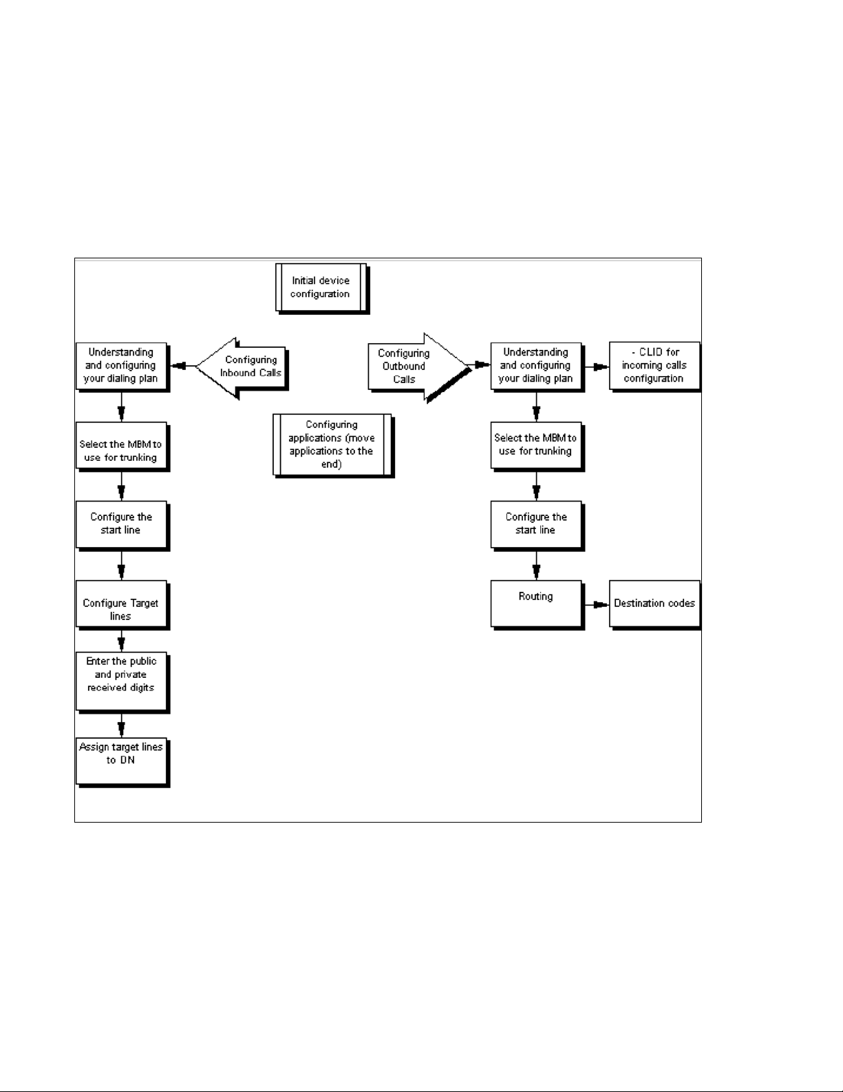
This guide describes how to configure and assign features, and provide basic
programming for the Avaya BCM. The flowchart below identifies the steps required to
configure your system for inbound and outbound traffic. For more information about
network planning information, planning and configuration prerequisites, and planning
checklists, see Avaya Business Communications Manager 6.0 Planning and
Engineering (NN40170-200).
Purpose
The concepts, operations, and tasks described in this guide relate to the Avaya BCM
software. This guide provides task-based information about how to assign features and
provide basic programming for the Avaya BCM.
Use Business Element Manager , S t artup Profile, and Telset Administration to configure
various Avaya BCM parameters.
In brief, the information in this guide explains:
• global telephony settings
• steps to configure DNs
• product features and how to assign them
About Avaya BCM
The Avaya BCM system provides private network and telephony management
capability to small and medium-sized businesses.
The Avaya BCM system enables you to create and provide telephony applications for
use in a business environment.
Audience
This guide is directed to installers who install, configure, and maintain Avaya BCM
systems. To use this guide, you must
• be an authorized Avaya BCM installer or administrator within your organization
• know basic Avaya BCM terminology
• be knowledgeable about telephony and IP networking technology
NN40170-502 Avaya Business Communications Manager 6.0 Configuration —Telephony May 2010 17
Page 18
Introduction
Prerequisites
Before you complete the following procedures, review the following prerequisites.
• Ensure all applicable keycodes are purchased and applied.
• Ensure all required MBMs are installed.
• Ensure market profile is selected.
18 NN40170-502 Avaya Business Communications Manager 6.0 Configuration —Telephony May 2010
Page 19

System telephony networking overview
The information in this chapter applies to both the BCM50 and the BCM450 platforms
running Avaya Business Communications Manager 6.0 (Avaya BCM 6.0).
The system supports both public and private networking for telephony traffic.
• The public network is created by PSTN trunk connections from a Central Office
terminating on a telephone system such as the Avaya BCM 6.0.
• A private network is created when the system is connected through dedicated PSTN
lines or VoIP trunks to other systems. This system can take several forms. At the
simplest level, your system may be behind a private PBX, which connects directly to
the Central Office. A more complicated system may be a node in a network of
systems of various types, where calls not only terminate at t he system, but calls can
need to be passed through the system to oth er nodes unconnected to the originating
node.
Refer to the following information:
• Basic system configurations (page 19)
• Private network parameters (page 26)
Basic system configurations
In the most basic application, your system can provide support for system telephones
to make and receive calls over public network (PSTN) lines.
Two basic system telephony configurations
The following provides a broad overview of the telephony setup for two of the most
common office-telephone configurations.
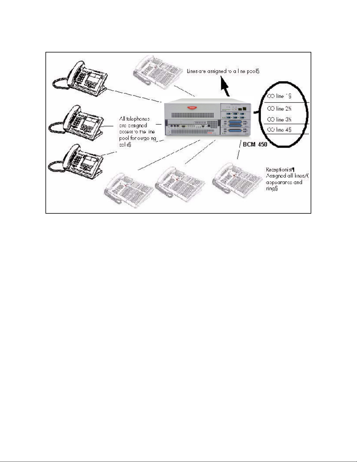
PBX system
This setup is for larger offices which have fewer CO lines than telephones. In this case
the lines are pooled, and the line pool access is assigned to all DNs. There may also be
a designated attendant with a telephone that has all lines individually assigned.
NN40170-502 Avaya Business Communications Manager 6.0 Configuration —Telephony May 2010 19
Page 20
System telephony networking overview
PBX system for BCM450
The following figure shows a PBX system for the BCM50.
20 NN40170-502 Avaya Business Communications Manager 6.0 Configuration —Telephony May 2010
Page 21
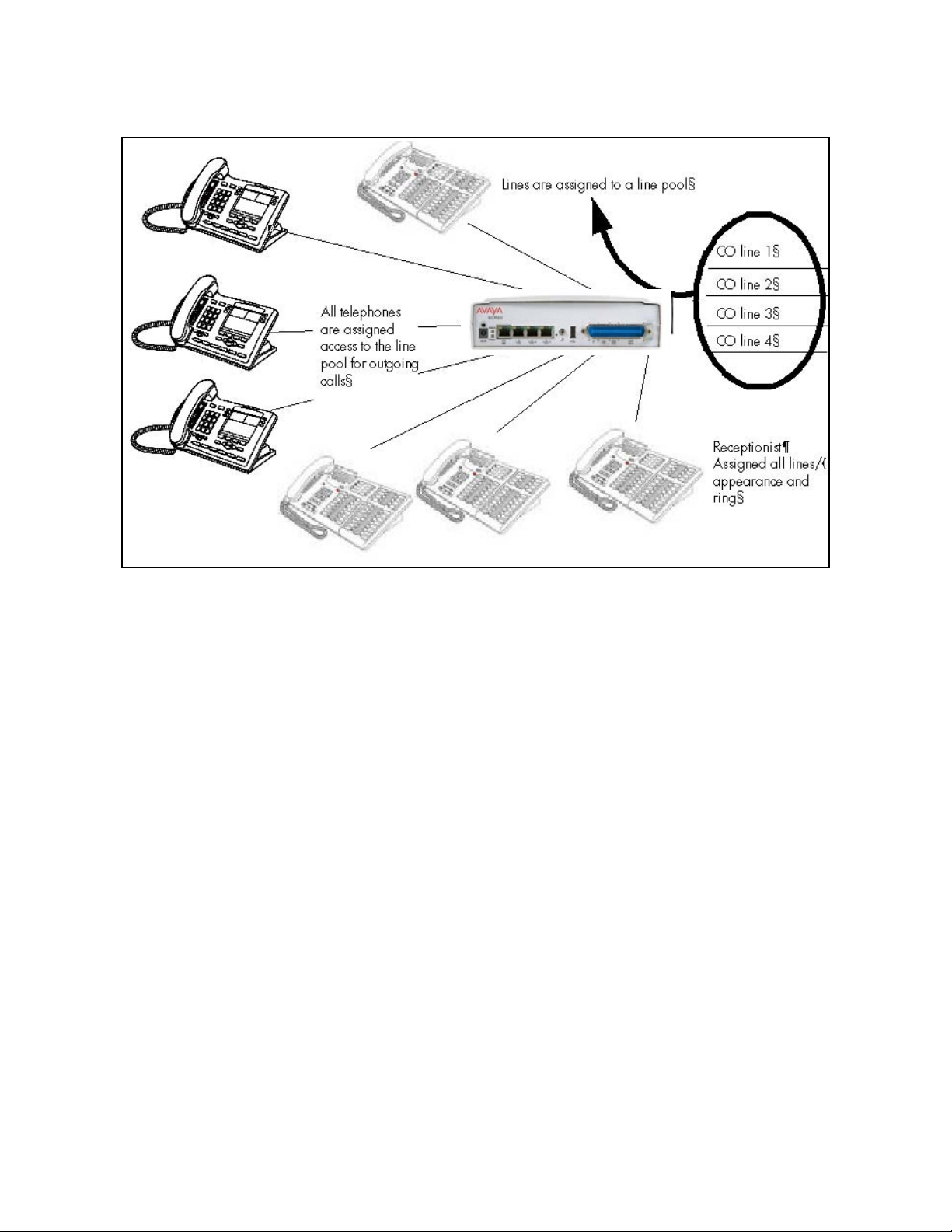
PBX system for BCM50
System telephony networking overview
BCM 50
Incoming calls
1 A call comes in on a line.
2 The receptionist answers the call and finds out who the call is for.
3 The receptionist transfers the call to a specific telephone (DN).
4 The person can pick up the call at that DN only.
Outgoing calls
1 User selects the intercom button or dials a line pool access code, which selects a line
in the line pool.
2 The user dials the outgoing telephone number.
DID system
This setup allows you to assign a dedicated phone number to each telephone. The CO
assigns a list of available numbers for each DID (Direct Inward Dial) line. You can
change your DN range to match these numbers, and you use t arget lines to match each
number with a DN.
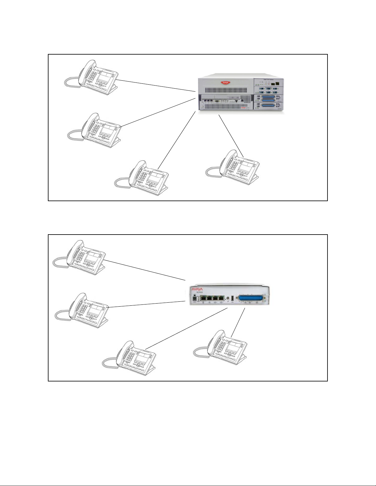
The following figure shows a DID system for the BCM450.
NN40170-502 Avaya Business Communications Manager 6.0 Configuration —Telephony May 2010 21
Page 22
System telephony networking overview
DID system for BCM 450
Target line mapped to
DN (4005)
Target line mapped to
DN (4006)
The following figure shows a DID system for BCM50.
DID system for BCM 50
Target line mapped to
DN (4007)
Target line mapped to
DN (4005)
Target line mapped to
DN (4006)
Target line mapped to
DN (4008)
CO DID line
i.e. 769
with range of call
numbers (4005 to
4020)
Target line mapped to
DN (4007)
Target line mapped to
DN (4008)
22 NN40170-502 Avaya Business Communications Manager 6.0 Configuration —Telephony May 2010
Page 23

Incoming calls
1 DID trunks are assigned to be auto-answer.
Attention: PRI lines are automatically set to auto-answer.
2 All DNs are assigned target lines.
3 A caller dials a system code and a DN. In the example shown above, it might be
769-4006.
4 The call comes into the trunk, which answers and maps the call on the target line
assigned to the matching received digits.
5 The DN assigned to that target line rings.
Y ou can assign unanswered or busy telephones to Call Forward to another DN, such as
a designated attendant or a voice-mail system.
Basic telephony routing
In a basic configuration, simple access codes (for example Line Pool Codes) are used
to access the PSTN network.
In a more complex configuration, more advanced destination codes are required to
access multiple PSTNs, private network resources, and remote nodes. Access to these
resources enables advanced features, such as tandem routing.
System telephony networking overview
Tandem calling to a remote PSTN
A system connected to a private network that uses dedicated circuits or VoIP circuits
can allow a user to dial directly to many other users, on different nodes, using a
coordinating dialing plan.
Using a private network saves on toll charges, and local charges, as fewer PSTN
accesses are required for internal and external calling. Several nodes located on one
site initiate their external local calls to a centralized Avaya BCM having a T1 or E1
termination to the PSTN. This type of configuration avoids multiple PSTN terminations
at other local nodes.
The same tandeming concepts can be applied to inbound calls. DID numbers dialed
from the PSTN can be processed and tandem routed out of the centralized system to
the localized remote nodes. For more information see, Creating tandem private
networks (page 33).
The following figure shows three types of callers. Each type of caller has a specific
method of accessing the other two BCM450 systems.
NN40170-502 Avaya Business Communications Manager 6.0 Configuration —Telephony May 2010 23
Page 24
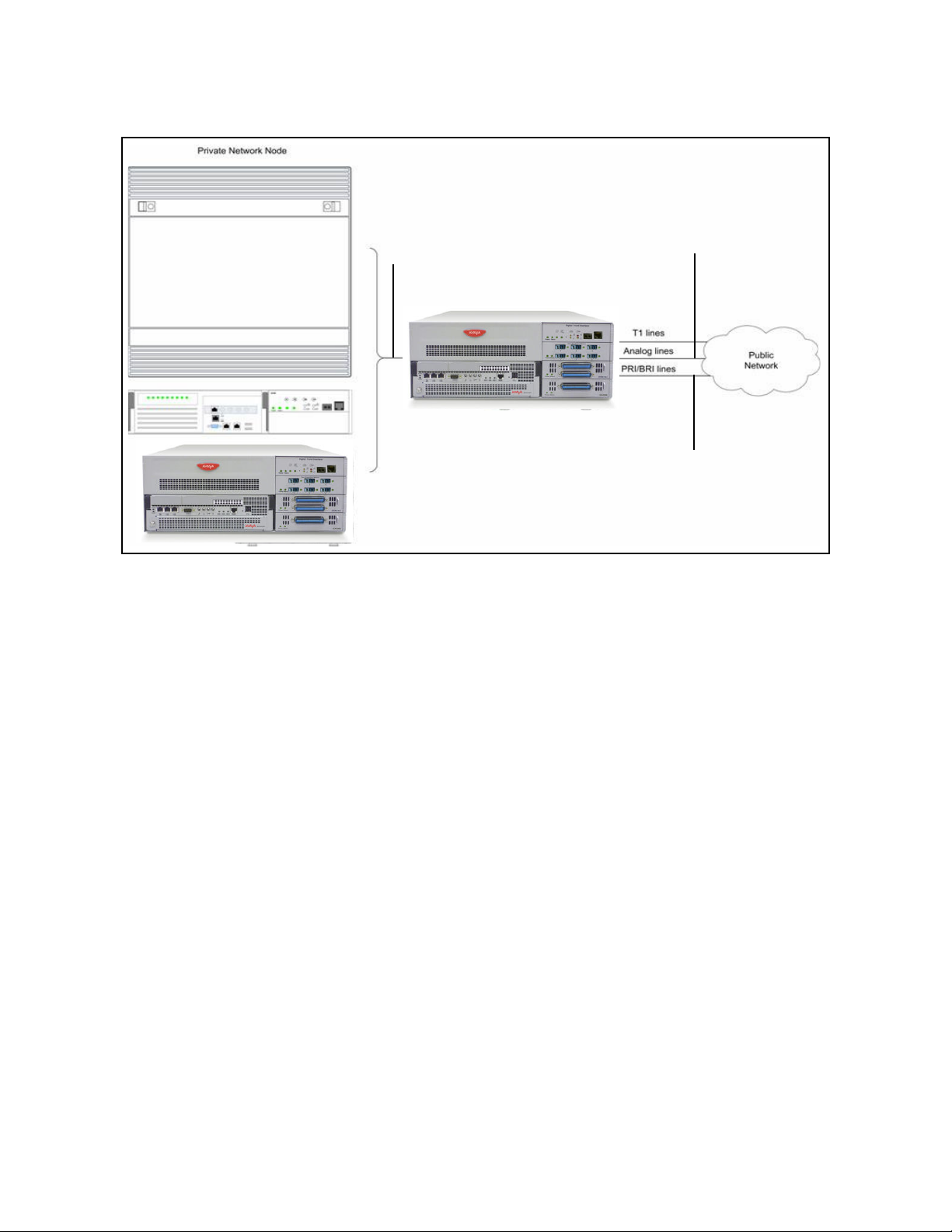
System telephony networking overview
Tandem dialing through a BCM450 to/from a private network
T1 E&M
PRI SL1
VoIP
T1/E1 lines
Analog lines
PRI/BRI lines
The following figure shows three types of callers. Each type of caller has a specific
method of accessing the other two BCM50 systems.
24 NN40170-502 Avaya Business Communications Manager 6.0 Configuration —Telephony May 2010
Page 25
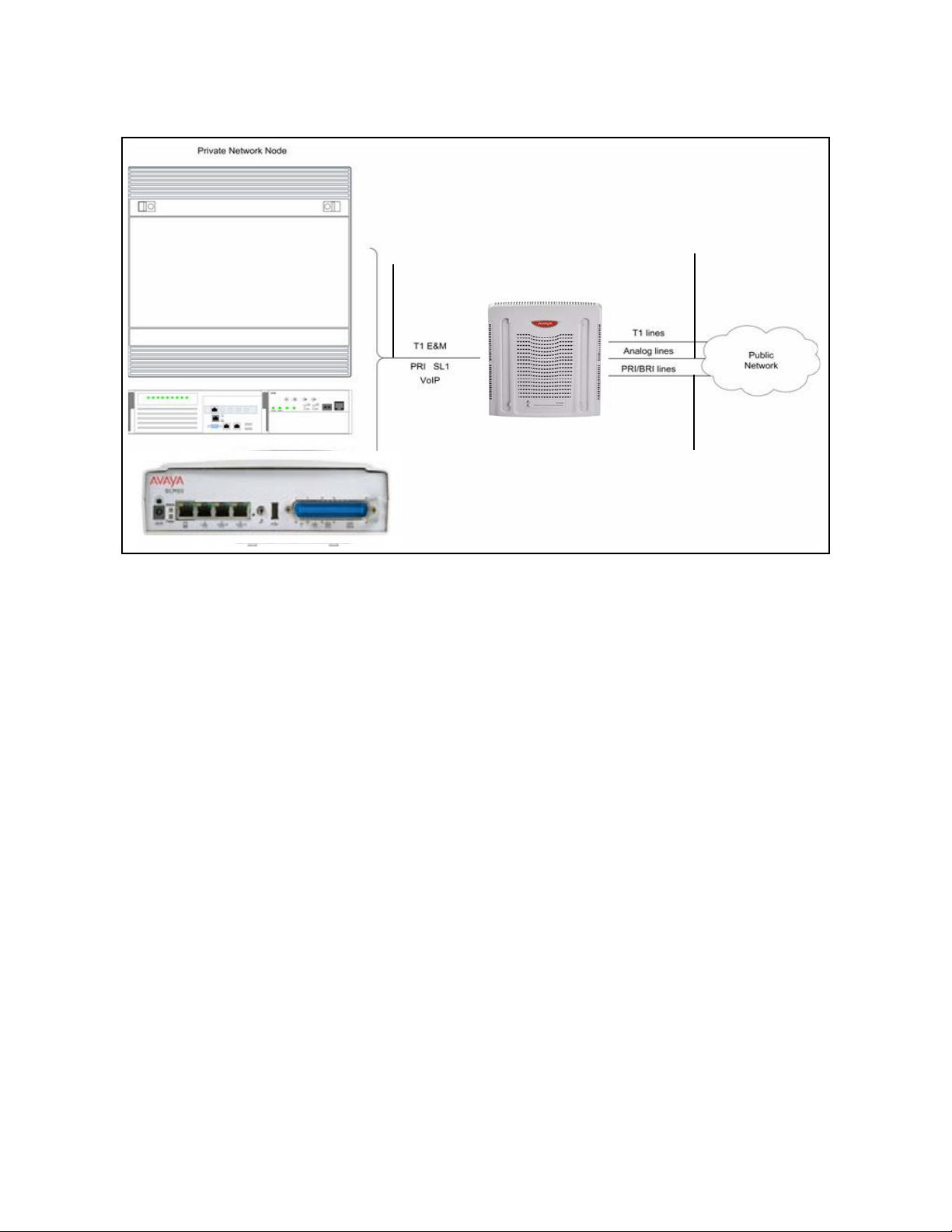
Tandem dialing through a BCM50 to/from a private network
System telephony networking overview
Callers using Avaya BCM
These callers can
• call directly to a specific telephone
• select an outgoing line to access a private network
T1 E&M
PRI SL1
VoIP
T1/E1 lines
Analog lines
PRI/BRI lines
• select an outgoing line to access features that are available on the private network
• select an outgoing central office line to access the public network
• use all of the Avaya BCM features
Callers in the public network
These callers use the public lines to
• call directly to one or more Avaya BCM DNs
• call into Avaya BCM and select an outgoing TIE line to access a private network
• call into Avaya BCM and select an outgoing central office line to access the public
network
• call into Avaya BCM and use remote features
NN40170-502 Avaya Business Communications Manager 6.0 Configuration —Telephony May 2010 25
Page 26

System telephony networking overview
Callers in the private network node
These callers use the private lines to
• call directly to one or more Avaya BCM DNs
• call into Avaya BCM and select an outgoing TIE line to access other nodes in a
private network
• call into Avaya BCM and select an outgoing central office line to access the public
network
• call into Avaya BCM and use remote features
System numbering and dialing plans
All systems on a private network must coordinate dialing plans, to ensure that calls get
directed to the correct network node. As well, routing becomes more complex,
especially if the system is not an end node and must be configured to relay calls to
nodes not directly connected to the system. The type of dialing plan supported by the
network determines whether each node also requires unique DNs.
Private network parameters
The following sections provide an overview of the system values that affect private
networking.
• Private networking protocols (page 26)
• Keycode requirements (page 27)
• Remote access to the network (page 27)
• Lines used for networking (page 27)
• Types of private networks (page 28)
Private networking protocols
The Avaya BCM supports the following protocols for private networking:
• PRI: ETSI QSIG, Avaya Voice Networking (MCDN)
•DPNSS
• BRI: ETSI QSIG
• T1: E&M
• VoIP trunks (with optional MDCN)
Attention: For the DTM-PRI configuration protocol, MCDN is referred to as SL-1 in
Business Element Manager.
26 NN40170-502 Avaya Business Communications Manager 6.0 Configuration —Telephony May 2010
Page 27

BCM systems can be networked together using T -1, PRI or V oIP trunks. PRI SL-1 lines
and VoIP trunks also offer the opportunity to use the MCDN protocol, which provides
enhanced trunking features and end-to-end user identification. If a Meridian 1 is part of
the MCDN network, the network can also provide centralized voice mail and auto
attendant off the Meridian.
Attention: MCDN networking requires all nodes on the network to use a common
Universal Dialing Plan (UDP) or a Coordinated Dialing Plan (CDP).
Keycode requirements
Keycodes are required to activate the protocols that are used to create private
networking, includi ng:
• VoIP Gateway keycodes
• an MCDN, DPNSS, or Q. Sig keycode, if you want to use a networking protocol
between the systems
You must purchase and install these keycodes before you can create any of the
networks described in this chapter. Consult with your Avaya distributor to ensure you
order the correct keycodes for the type of network you want to create.
System telephony networking overview
Remote access to the network
Authorized users can access TIE lines, central office lines, and features from outside
the system. Remote users accessing a private network configured over a large
geographical area can avoid toll charges.
Attention: You cannot program a DISA DN or Auto DN to a VoIP trunk, as they act as
auto-answer trunks from one private network to the n ext. Howe ver, you can configure
VoIP line pools with remo te access packages so that callers can access telepho nes or
the local PSTN on remote nodes on a tandemed network that use V oIP trunks between
systems.
Lines used for networking
External (trunk) lines provide the physical connection between Avaya BCM and other
systems in a private or public network.
The BCM50 numbers physical lines from 061 to 124. Default numbering depends on the
type and connection to the BCM50 (EXP1 - EXP2)
VoIP trunks: Although a VoIP gateway does not use physical lines, it is easier to think
of them that way . BCM450 support s a dynamically configurable number of IP trunk line
numbers, from 0 to 130. In the BCM50, lines 001 to 012 are used for VoIP trunk
functionality.
NN40170-502 Avaya Business Communications Manager 6.0 Configuration —Telephony May 2010 27
Page 28

System telephony networking overview
Avaya BCM networking configurations that use PRI and T1 lines, requ ire specific DTM
modules.
• DTMs configured for PRI are used for incoming and outgoing calls (two-way DID).
Incoming calls are routed directly to a BCM DN that has a properly configured and
assigned target line. All outgoing calls made through PRI, are initiated using the
destination codes.
• DTMs configured for T1/E1 can have digital lines configured as Groundstart, E&M,
Loop, or DID.
Target lines are virtual communication paths between trunks and telephones on the
BCM system. They are incoming lines only , and cannot be selected for outgoing calls or
networking applications. With target lines, you can concentrate incoming calls on fewer
trunks. This type of concentration is an advant age of DID lines. Avaya BCM t arget lines
allow you to direct each DID number to one or more telephones. VoIP trunks also
require target lines to direct incoming traffic.
In BCM450, there is a maximum of 639 target lines. In BCM 50, there is a maximu m of
208 target lines.
Telephones can be configured to have an appearance of analog lines or multiple
appearances of target lines.
Attention: PRI B-channels cannot be assigned as line appearances. PRI B-channels,
or “trunks”, can only be configured into PRI line pools for inbound routing through target
lines with receive digits or outbound routing through destination codes.
Types of private networks
There are several ways you can create private networks. Configuration can be based
on such things as cost of trunks, proximity of network nodes, size of the private network,
and business requirements for communications.
VoIP-based networking also requires an understanding of IP features such as codecs,
jitter buffers, Quality of Service (QoS) function, and silence compression.
The services provided within networks is based on the type of trunks and the protocols
assigned to the trunks. All trunks within the network should be running the same
protocols, to provide a technically sound and stable network.
The following links are procedures to set up basic networks to advanced networks, using
the support protocols within Avaya BCM:
• Routing-based networks using T1 E&M lines (page 29)
• PRI networking using Call-by-Call services (page 31)
• PRI SL-1/Q.Sig/DPNSS and VoIP trunk networking (page 32)
28 NN40170-502 Avaya Business Communications Manager 6.0 Configuration —Telephony May 2010
Page 29

Routing-based networks using T1 E&M lines
By properly planning and programming routing tables and destination codes, an installer
can create a dialing plan where T1 E&M lines between BCM systems are available to
other systems in the network.
The following figure shows a network of three Avaya BCM450 systems. Two remote
systems connect to a central system.
Dialing plan for T1 E&M routing network of BCM450s
System telephony networking overview
The following figure shows a network of three BCM50 systems. Two remote systems
connect to a central system.
NN40170-502 Avaya Business Communications Manager 6.0 Configuration —Telephony May 2010 29
Page 30
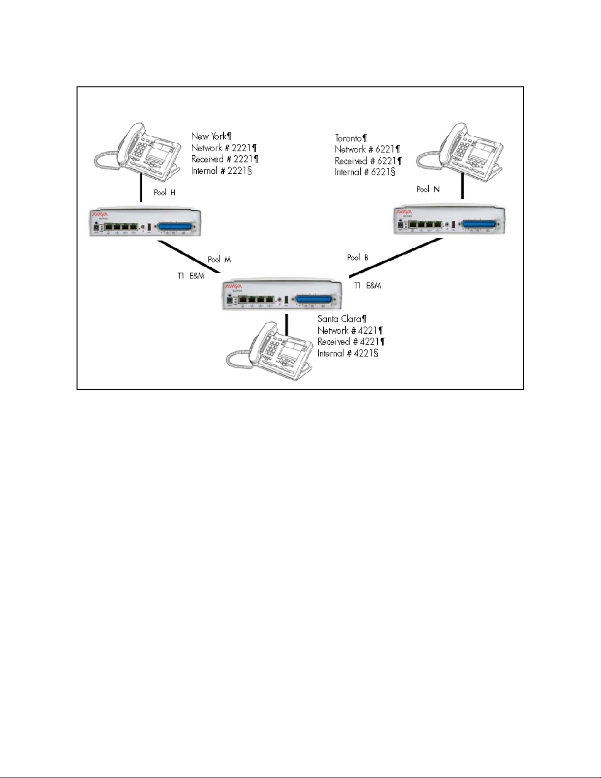
System telephony networking overview
Dialing plan for T1 E&M routing network of BCM50s
Each system must be running Avaya BCM software. Each system must be equipped
with target lines and a DTM with at least one T1 E&M line.
The call appears on the auto answer line on the Avaya BCM in Santa Clara as 6-221.
Because 6 is programmed as a destination code for Toronto on the Santa Clara system,
another call is placed using route 002 from Santa Clara to Toronto. At the Toronto
system, the digits 6-221 are interpreted as a target line Private received number. The
call now alerts at DN 6221 in Toronto.
Attention: Network calls that use routes are subject to any restriction filters in effect.
If the telephone used to make a network call has an a ppearance of a line used by the
route, the call will move from the intercom button to the Line button. The telephone
used to make a network call must have access to the line pool used by the route.
Network calls are external calls, even though they are dialed as if they were internal
calls. Only the features and capabilities available to external calls can be used.When
programming a button to dial a Network number automatically (autodial), network calls
must be treated as external numbers, even though they resemble internal telephone
numbers. Routes generally define the path between your Avaya BCM switch and
another switch in your network, not other individual telephones on that switch.
30 NN40170-502 Avaya Business Communications Manager 6.0 Configuration —Telephony May 2010
Page 31

PRI networking using Call-by-Call services
The example shown in the following figure highlights the use of PRI Call-by-Call
services. It shows two offices of a company, one in New York and one in Toronto. Each
office is equipped with a BCM450 system and a PRI line. Each office has to handle
incoming and outgoing calls to the public network. In addition, employees at each of fice
often have to call colleagues in the other office. For more information, see Configuring
call-by-call services and PRI lines (page 214).
PRI networking using Call-by-Call Services on BCM 450
System telephony networking overview
The example shown in the following figure shows two offices, where each office is
equipped with a BCM50 system and a PRI line.
NN40170-502 Avaya Business Communications Manager 6.0 Configuration —Telephony May 2010 31
Page 32

System telephony networking overview
PRI networking using Call-by-Call Services on BCM50
To reduce long distance costs, and to allow for a coordinated dialing plan between the
offices, private lines are used to handle inter-office traffic.
If call-by-call services were not used, each BCM system might have to be equipped with
the following trunks:
• 12 T1 DID lines needed to handle peak incoming call traffic
• eight T1 E&M lines needed to handle inter-office calls
• eight lines needed to handle outgoing public calls
PRI SL-1/Q.Sig/DPNSS and VoIP trunk networking
Y ou can use PRI SL-1 trunks and VoIP trunk s to create private networks between Avaya
BCM systems or between Avaya BCM systems and larger call servers such as Meridian
1, Succession 1000/M, DMS-100/ 250 and CSE.
ETSI-QSIG and DPNSS private networking is configured very similarly, although
network features may be supported slightly differently due to local line and network
requirements.
If the MCDN protocol is added to this type of private network, the network provides
additional network management features, as well as allowing centralized voice mail
features to be available to all nodes on the network.
32 NN40170-502 Avaya Business Communications Manager 6.0 Configuration —Telephony May 2010
Page 33

System telephony networking overview
The following topics describe the different aspects of SL-1 and MCDN private
networking.
• System dialing plans (page 33)
• Creating tandem private networks (page 33)
• Understanding Avaya Voice Networking (MCDN) network features (page 35)
• Networking with ETSI QSIG (international systems only) (page 40)
• Private networking with DPNSS (international only) (page 50)
The type of network you require depends on the equipment in the net work, and how you
want to use the network.
With MCDN, you can tie a set of Avaya BCM systems together with PRI SL-1 (MCDN)/
ETSI-QSIG, DPNSS, or VoIP trunks to create a tandem network. This type of network
provides the additional advantage of providing private line access to local PSTNs for all
the nodes on the network.
Attention: A keycode is required to use the Avaya Voice Networking functionality,
which is referred to as SL-1 in Business Element Manager.
System dialing plans
Both of these types of networks require similar setup s for dialing plans and routing. Each
node must have a way to route external calls to the adjacent node or nodes. To do this,
all nodes must have the same Private DN lengths.
You use routing and a private dialing plan to control calls over the network. Each
example in this section describes the routing configurations that are required to support
calls over the network.
Depending on the type of dialing plan you choose , each node must also have a un ique
location or steering code so the calls can be correctly routed through the nodes of the
network. MCDN networks also require a Private Network ID, which is supplied by the
Meridian network administrator to define how the Meridian system identifies each node.
Creating tandem private networks
You can tie a number of Avaya BCM systems together with SL-1 lines. This tandem
network provides you with the benefits of end-to-end name display and toll-free calling
over the SL-1 private link. Each Avaya BCM system becomes a node in the network. In
this type of network, you must ensure that each Avaya BCM system, known as a node
of the network, is set up to route calls internally as well as to other nodes on the system.
This means each node must have a route to the immediately adjacent node, and the
correct codes to distribute the called numbers. Each node must have a unique
identification number, which is determined by the type of dialing plan chosen for the
network.
NN40170-502 Avaya Business Communications Manager 6.0 Configuration —Telephony May 2010 33
Page 34

System telephony networking overview
Also, you can save costs by having a public network connection to only one or two
nodes, and routing external calls from other nodes out through the local PSTN, thus
avoiding toll charges for single calls.
Attention: Y ou can also use V oIP trunks between some or all of the nodes. The setup
is the same, except that you need to create gateway records for each end of the trunk,
and routing tables to accommodate the gateway codes, or you can configure a
gatekeeper . For more information, see Avaya Business Co mmunications Manager 6.0
Planning and Engineering (NN40170-200).
Routing for tandem networks
In tandem networks, each node needs to know how to route calls that do not terminate
locally. To do this, you set up routes for each connecting node by defining destination
codes for each route.
If the node is also connected to the public network, the usual routing is required for that
connection.
The following tables show the routing tables for Node A and Node C for external and
internal terminating calls.
Attention: The PRI and VoIP trunks are en bloc dialing lines, so all dialed digits are
collected before being dialed out.
Node A destination code table, external termination
Route Absorb length Destination code (public DNs)
4 (PSTN) 1 91604
3 (Node B) 0 91403762 (Node B)
3 (Node B) 0 91403765 (Node E)
4 (PSTN) 1 9140376* (not internal network)
4 (PSTN) 1 914037* (not internal network)
4 (PSTN) 1 91403* (not internal network)
4 (PSTN) 1 9* (not internal network)
* This wild card represents a single digit.
Node A destination code table, internal termination
Route Absorb length Destination code (public DNs)
3 (Node B) 0
3 (Node B) 0
5 (Node C) 0 393 (Node C)
392 (Node B)
395 (Node E)
34 NN40170-502 Avaya Business Communications Manager 6.0 Configuration —Telephony May 2010
Page 35

System telephony networking overview
Node A destination code table, internal termination
Route Absorb length Destination code (public DNs)
5 (Node C) 0 394 (Node D)
5 (Node C) 0 396 (Node F)
Node C destination code table, external termination
Route Absorb length Destination code (public DNs)
3 (Node B) 0 91613764 (Node D)
3 (Node B) 0 91613766 (Node F)
4 (PSTN) 1 9161376* (not internal network)
4 (PSTN) 1 916137* (not internal network)
4 (PSTN) 1 91613* (not internal network)
4 (PSTN) 1 9161* (not internal network)
4 (PSTN) 1 916* (not internal network)
4 (PSTN) 1 91* (not internal network)
4 (PSTN) 1 9 (not internal network)
* This wild card represents a single digit.
Node C destination code table, internal termination
Route Absorb length Destination code (public DNs)
3 (Node D) 0
3 (Node D) 0
5 (Node A) 0 391 (Node A)
5 (Node A) 0 392 (Node B)
5 (Node A) 0 395 (Node E)
394 (Node D)
396 (Node F)
Understanding Avaya Voice Networking (MCDN) network features
When you connect your Avaya BCM systems thro ugh PRI-SL-1/ETSI QSIG/DPNSS or
VoIP trunks, and activate the MCDN protocol, your network provides a number of
network call features. You can use this protocol to network other Avaya BCM systems,
such as the tandem system shown in Creating tandem private networks (page 33),
Norstar systems, Meridian 1 systems, Succession systems, DMS-100 systems or CSE
systems.
The following sections describe the MCDN features that are provided by all SL-1/VoIP
networks where MCDN is active. The features affect call redirection and trunking
functions.
NN40170-502 Avaya Business Communications Manager 6.0 Configuration —Telephony May 2010 35
Page 36

System telephony networking overview
Centralized messaging
• Network Call Redirection Information (page 36)
Centralize trunking
• ISDN Call Connection Limitation (page 37)
• Trunk Route Optimization (page 38)
Network Call Redirection Information
Network Call Redirection Information (NCRI) builds on the following Avaya BCM
features:
• External Call Forward
• Call Transfer
• Call Forward
NCRI adds the ability to redirect a call across an MCDN network using Call Forward (All
Calls, No Answer, Busy) and Call Transfer features. The call destination also receives
the necessary redirection information. This feature allows the system to automatically
redirect calls from within a Avaya BCM system to the mail system, such as Meridian
Mail, which resides outside the Avaya BCM system on the Meridian 1.
The following figure shows an example where user A calls user B on the same BCM450.
If user B is busy or not answering, the call automatically gets transferred to a Meridian
Mail number (user C) across an MCDN link between the BCM450 system and the
Meridian 1 system where the mailboxes are set up.
Network call redirection path on BCM450
36 NN40170-502 Avaya Business Communications Manager 6.0 Configuration —Telephony May 2010
Page 37

The following figure shows an example where user A calls user B on the same BCM50.
If user B is busy or not answering, the call automatically gets transferred to a Meridian
Mail number (user C) across an MCDN link between the BCM50 system and the
Meridian 1 system where the mailboxes are set up.
Network call redirection path on BCM50
System telephony networking overview
ISDN Call Connection Limitation
The ICCL (ISDN Call Connection Limitation) feature piggybacks on the call initiation
request and acts as a check at transit PBX points to prevent misconfigured routes or
calls with errors from blocking channels.
This feature adds a transit/tandem counter to a call setup message. This counter is
compared at each transit PBX with a value programmed into the transit PBX, in a range
from 0 to 31. If the call setup counter is higher than the PBX value, the call will be
blocked at the PBX system and cleared back to the network. This prevents calls from
creating loops that tie up lines.
The following figure illustrates how a call might loop through a network if the BCM450 is
not set up with ICCL.
NN40170-502 Avaya Business Communications Manager 6.0 Configuration —Telephony May 2010 37
Page 38

System telephony networking overview
Call loop on BCM450 without ICCL
The figure demonstrates how a call might loop through a network if the BCM50 is not
set up with ICCL.
Call loop on BCM50 without ICCL
Trunk Route Optimization
Trunk Route Optimization (TRO) finds the most direct route through the network to send
a call between nodes. This function occurs during the initial alerting phase of a call.
38 NN40170-502 Avaya Business Communications Manager 6.0 Configuration —Telephony May 2010
Page 39

To set Avaya BCM configurations:
• Select Configuration > Dialing Plan > Private Network, and select the check box
beside TRO in the MCDN pane.
• Configure call routing for all optimal routes.
• Configure call forward (All Calls, No Answer, Busy) or Selective Line Redirection to
use the optimal routes.
This feature avoids the following situation: A call originating from a Avaya BCM system
may be networked to a Meridian system, which, in turn, is networked to another Meridian
system, which is the destination for the call. If the call routes through the first Meridian
(M1) to reach the second Meridian (M2), two trunks are required for the call. An optimal
choice is a straight connection to M2. This finds these connections and overrides the
less-efficient setup.
The following figure shows two call paths. The first route, through the Meridian,
demonstrates how a call might route if TRO is not active. The second route, that
bypasses the Meridian, demonstrates how TRO selects the optimum routing for a call.
Call paths from BCM 450 with and without TRO
System telephony networking overview
The following figure shows two call paths. The first route, through the Meridian,
demonstrates how a call might route if TRO is not active. The second route, that
bypasses the Meridian, demonstrates how TRO selects the optimum routing for a call.
NN40170-502 Avaya Business Communications Manager 6.0 Configuration —Telephony May 2010 39
Page 40

System telephony networking overview
Call paths from BCM50 with and without TRO
Networking with ETSI QSIG (international systems only)
ETSI QSIG is the European standard signaling protocol for multi-vendor peer-to-peer
communications between PBX systems and/or central offices (see ETSI Euro network
services (page 42)).
The figure ETSI QSIG networking using BCM450 (page 41) illustrates an ETSI QSIG
network using BCM450. Note that this is exactly the same setup as that shown in the
MCDN section for North America. The hardware programming for ETSI QSIG is
described in Hardware programming for branch offices (page 42). All other
configurations are the same as those shown in the MCDN section for North America.
40 NN40170-502 Avaya Business Communications Manager 6.0 Configuration —Telephony May 2010
Page 41

ETSI QSIG networking using BCM450
System telephony networking overview
Network #2221
Received #2221
Internal #2221
PRI/BRI ETSI
QSIG
PBX
BCM West End Branch BCM East End Branch
PRI (public protocol)
Central
Office
Network #6221
Received #6221
Internal #6221
PRI/BRI
ETSI QSIG
DN #4221
The following figure illustrates an ETSI QSIG network using BCM50. Note that this is
exactly the same setup as that shown in the MCDN section for North America. The
hardware programming for ETSI QSIG is described in Hardware programming for
branch offices (page 42). All other configurations are the same as those shown in the
MCDN section for North America.
NN40170-502 Avaya Business Communications Manager 6.0 Configuration —Telephony May 2010 41
Page 42

System telephony networking overview
ETSI QSIG networking using BCM50
Network #2221
Received #2221
Internal #2221
PRI/BRI ETSI
QSIG
PBX
BCM West End Branch BCM East End Branch
PRI (public protocol)
Central
Office
Network #6221
Received #6221
Internal #6221
PRI/BRI
ETSI QSIG
DN #4221
The following table lists the settings for some of the hardware parameters for ETSI QSIG
networking example shown above.
Hardware programming for branch offices
West-end office East-end office
Hardware
programming
DTM/BRIM PRI/BRI Hardware
Protocol ETSI QSIG Protocol ETSI QSIG
BchanSeq Ascend (PRI
only)
ClockSrc Primary ClockSrc Primary
programming
ETSI Euro network services
If your system has ETSI ISDN BRI/PRI lines, you can activate the malicious call
identification (MCID) and Network Diversion features. Advice of charge-end call (AOCE)
is active if your service provider has activated that service on the line.
When the features are activated, users can
• display a call charge
DTM/BRIM PRI/BRI
BchanSeq Ascend (PRI
only)
42 NN40170-502 Avaya Business Communications Manager 6.0 Configuration —Telephony May 2010
Page 43

• redirect calls over the ETSI ISDN BRI/PRI line to the outside network
• tag malicious calls
Advice of Charge-End of Call (AOCE) — AOCE is a supplementary service available
from your service provider on ETSI ISDN BRI/PRI links. This feature allows the Avaya
BCM user to view the charges for an outgoing call after the call completes. This
information is also reported to the Call Detail Reporting Application. The information can
be provided in currency or charging units, depending on how the feature is set up by
your service provider.
To invoke the feature, the user presses FEATURE 818.
DPNSS 1 services
The Digital Private Network Signaling System (DPNSS 1) is a networking protocol
enhancement that extends the private networking capabilities of existing Avaya BCM
systems. It is designed to offer greater centralized functionality for operators, giving
them access to Avaya BCM features over multiple combined networks.
Attention: The DPNSS feature is dependent on which region loade d on your system
at startup and that a software keycode was entered to enable the feature.
System telephony networking overview
For more information, see
• DPNSS 1 capabilities (page 43)
• DPNSS 1 features (page 44)
• Private networking with DPNSS (international only) (page 50)
DPNSS 1 allows a Avaya BCM local node, acting as a terminating node, to
communicate with other PBXs over the network. For example, corporate offices
separated geographically can be linked over DPNSS 1 to other Avaya BCM nodes,
Avaya BCM the restrictions of the PSTNs to which they may be connected. Connected
Avaya BCM nodes can therefore function like a private network, with all features of
Avaya BCM accessible.
Attention: Avaya BCM DPNSS 1 works as a terminating node only. Avaya
BCM-to-BCM DPNSS is not supported.
You can use DPNSS 1 features on any Avaya BCM telephone. On most Avaya BCM
telephones, you must use specific keys and/or enter a number code to access the
features.
DPNSS 1 capabilities
A single Avaya BCM node, acting as a terminating node on the network, supports the
following capabilities over DPNSS 1 lines:
• Direct Dial Inward (DDI) for incoming calls.
NN40170-502 Avaya Business Communications Manager 6.0 Configuration —Telephony May 2010 43
Page 44

System telephony networking overview
• Originating Line Identification (OLI) for incoming and outgoing calls:
— For incoming calls, the Calling Line Identification (CLI/CLID) information is
displayed to the user on telephones with line display . This must be configured in
programming.
— For outgoing calls, the directory number of the originating party is sent out as
OLI.
• Terminal Line Identification (TLI) for incoming and outgoing calls. Referred to as
Called Line Identification.
• Selective Line Redirect (SLR) and External Call Forward (ECF) implemented on
calls between DPNSS 1, and BRI/PRI, DASS2, and analog lines.
• These remote access features are supported on DPNSS: DDI, line pool access
code, destination codes and remote page feature codes.
Keycodes are required to enable DPNSS 1.
DPNSS to Embark connections
DPNSS lines connected to an Embark switch perform call redirection/diversion using
the Call Forward feature to create a tandem link b ack to the switch. Since this is different
from other switches, you must select the type of switch DPNSS will be connecting to
when you do module programming.
Before you program Call Forwarding, ensure that
• Both real channels and virtual channels are provisioned.
• Destination or line pool codes are programmed for the DPNSS to Embark link.
Also, during programming for Call Forward No Answer and Call Forward on Busy, when
you enter the Forward to: digits, the system does a validation check with the switch on
the number. (Configuration > Telephony > Sets > Active Sets > Line Access)
DPNSS 1 features
DPNSS features (page 44) lists available features that can be programmed over
DPNSS lines:
DPNSS features
Feature BCM450 BCM50
Three-party service supported supported
Conference calls supported not supported
Diversion feature supported supported
Redirection feature supported supported
Executive intrusion supported supported
Call offer supported supported
44 NN40170-502 Avaya Business Communications Manager 6.0 Configuration —Telephony May 2010
Page 45

System telephony networking overview
DPNSS features
Feature BCM450 BCM50
Route optimization supported supported
Loop avoidance supported supported
Message Waiting Indication not supported supported
The following parameters can be configured for DPNNS 1 lines:
• Line type
•Prime set
•CLID set
• Auto privacy
•Answer mode
• Auxiliary ringer
• Full autohold
Some features are transparent to the user, but must be programmed to be activated.
Others are available for end-user programming at the telephone. Details about these
features are given in the following sections.
Three-party service
Three Party Service is a DPNSS 1 feature for Avaya BCM that is similar to the Avaya
BCM Conference feature.
The Three Party Service allows a user, usually an operator, to establish a three-party
conference by calling two other parties from one telephone. Once the connection is
made, the controlling party can hang up, leaving the other two connected. The
controlling party can even put one party on hold, and talk to the other party.
Attention: Avaya BCM does not support Hold over the DPNSS link it self. This means
that the conferenced party on the dist ant end of the network cannot place a Three Party
Service call on Hold.
This feature is designed to allow operators to assist in the connection of calls from one
main location.
Conference calls
To initiate or disconnect from a conference call on a Avaya BCM system over DPNSS
1, use the procedure described in the Avaya Business Communications Manager 6.0
Configuration — Devices (NN40170-500).
NN40170-502 Avaya Business Communications Manager 6.0 Configuration —Telephony May 2010 45
Page 46

System telephony networking overview
Attention: Three Party Service is supported on model Avaya 7000 telephones, but in
a receive-only fashion. These telephone types cannot initiate Three Party Service. For
more information about these telephone types, see the Avaya Business
Communications Manager 6.0 Installation — Devices (NN40170-304) (model Avaya
7000 Deskphones, supported in Europe only).
Diversion feature
Diversion is a DPNSS 1 feature for Avaya BCM that allows users to forward their calls
to a third party on the DPNSS 1 network. This feature is similar to Call Forward on A vaya
BCM but takes advantage of the broader capabilities of DPNSS.
There are five variations of Diversion: Call Diversion Immediate, Call Diversion On
Busy, Call Diversion On No Reply, Bypass Call Diversion, and Follow-me Diversion.
These variations are described below:
• Diversion Immediate diverts all calls to an alternate telephone. This function is
programmed by the user at their telephone.
• Diversion On Busy diverts all calls to an alternate telephone when a telephone is
busy. You can program this feature in the Business Element Manager.
• Diversion On No Reply diverts calls that go unanswered after a specified amount of
time. You can program this feature in the Business Element Manager.
• Bypass Call Diversion overrides all call forward features active on a telephone over
a DPNSS line. An incoming call to the telephone will not be forwarded; instead, the
telephone will continue to ring as if call forward were not active. This feature is used
to force a call to be answered at that location. Bypass Call Diversion is a receive-only
feature on Avaya BCM and cannot be used from a Avaya BCM telephone.
• Follow-me Diversion is also a receive-only feature. It allows the call-forwarded
destination to remotely change the Avaya BCM call-forwarding programming (Call
Forward All Calls [CFAC] feature) to a different telephone.
Attention: Avaya BCM CFAC must be active, and the destination set/PBX system
must support the feature.
For example, user A forwards all calls to telephone B, a temporary office. Later , user A
moves on to location C. The user does not have to be at telephone A to forward calls t o
location C. Using telephone B and Follow-me Diversion, the user can forward calls from
A to location C.
Follow-me diversion can be cancelled from the forwarded location.
• Diversion on Busy and Diversion on No Reply cannot be cancelled from the
forwarded telephone. These are programmable only by an installer and not by the
user.
46 NN40170-502 Avaya Business Communications Manager 6.0 Configuration —Telephony May 2010
Page 47

System telephony networking overview
• If multiple telephones are programmed to take a call, the first telephone to respond
will act. All other telephones responding are ignored. Therefore, if the first telephone
to respond has Diversion enabled, this feature will be invoked.
For restrictions by telephone type
• all variations supported on Avaya BCM digital and IP telephones
• ATA2/ASM8+—all variations supported on an ATA
• ISDN—all variations supported on ISDN telephones, except Diversion on Busy and
CFWD Busy
For diversion, set Diversion for DPNSS in the same way as Call Forward. You will need
to enter the end DN when prompted. Y ou may also need to include the DPNSS 1 routing
number.
Redirection feature
Redirection is a DPNSS 1 feature similar to Avaya BCM Transfer Callback. With
Redirection, a call awaiting connection, or reconnection, is redirected by the originating
party to an alternate destination after a time-out period. Failed calls can also be
redirected. Priority calls are not redirected.
Attention: The address to redirect depends on the history of the call. Calls that have
been transferred are redirected to the party that transferred them. In all other cases,
the address to redirect is the one registered at the PBX system originating the
redirection.
Attention: Avaya BCM does not support the redirection of Avaya BCM-originated
calls, even over DPNSS 1.
The Diversion on No Reply feature takes precedence over Redirection.
For restrictions by telephone type
• For telephones with a single line display, the number key (#) acts as MORE
and the
star key (*) acts as VIEW
• ISDN—all variations supported on ISDN telephones
For setting redirection, the timer used for the network Callback feature is also used for
redirection.
Executive intrusion
Executive Intrusion (EI) is a DPNSS 1 feature that allows an operator, or other calling
party , to intrude on a line when it is busy. An example of the use of this feature is to make
an important announcement when the recipient is on another call.
NN40170-502 Avaya Business Communications Manager 6.0 Configuration —Telephony May 2010 47
Page 48

System telephony networking overview
EI is similar in functionality to Avaya BCM Priority Call, but it is a receive-only feature on
Avaya BCM telephones. EI cannot be initiated from a Avaya BCM telephone. The
person using this feature must be on another PBX system on the DPNSS 1 network.
When EI is used to intrude on a call in progress, a three-way connection is established
between the originating party and the two parties on the ca ll. The result is very much like
a conference call. When one of the three parties clears the line, the other two remain
connected, and EI is terminated.
For restrictions by telephone type
• ATA2/ASM8+—supported
• ISDN—not supported
The telephone receiving the intrusion displays Intrusion Call. A warning indication tone
will sound after intrusion has taken place, and the standard conference call tone will
sound every 20 seconds.
For intrusion levels, whether a telephone accepts or rejects an Executive Intrusion
request depends on the level of intrusion protection programmed. Each telephone (DN)
has an Intrusion Capability Level (ICL) and four Intrusion Protection Levels (IPL).
When the ICL of the intruding telephone is higher than the IPLs of both telephones on
the active call, EI occurs. Avaya recommends that you set the IPLs of most A vaya BCM
telephones to the default of None, or Low or Medium.
Intrusion levels are described as follows:
• ICL: determines the ability of the attendant to intrude. As long as the ICL is higher
than the IPL of the wanted party, EI is allowed. Because EI is a receive-only feature,
the ICL cannot beset on Avaya BCM.
• IPL: determines the ability of the attendant to refuse intrusion. If the IPL is lower than
the ICL of the originating party, EI is allowed. For general purposes setting the IPL
to None, Low or Medium is recommended, unless intrusion is not wanted.
Call Offer
Call Offer over DPNSS 1 allows a calling party to indicate to the wanted party that there
is an incoming call available, even though there is no answer button available to present
the call on the telephone. The intended recipient can ignore, accept, or decline the
offered call. Call Offer is useful in increasing the call-coverage capability of a Avaya
BCM system, and helps to lift the network processing load. It is a receive-only cap ability
on Avaya BCM; incoming calls are initiated at another PBX system on the DPNSS 1
network.
An example of Call Offer in use is an operator or attendant who has a number of calls
coming in at once. The operator can call offer one call and move to the next without
waiting for the first call to be answered.
48 NN40170-502 Avaya Business Communications Manager 6.0 Configuration —Telephony May 2010
Page 49

System telephony networking overview
When a Call Offer is made by the originating exchang e, the target t elephone displays a
message, and a tone is heard. When an offered call arrives on telephones with line
display, the user sees XX...X wtng if the calling party ID is available and CLID is
enabled. If CLID is not available or CLID is disabled, Line XXX waiting appears (th e line
name associated with the call). If there are more than 11 digits in the incoming number,
only the last 10 will display.
If Call Queuing is programmed for the system, the display shows Release Line XXX.
This is the line name of the highest-priority queued call if it is an offered call.
Restrictions by telephone type include
• model Avaya 7000 telephone — associated LED or LCD flashes, and a tone is heard
(model Avaya 7000 Deskphones, supported in Europe only.)
• ATA2/ASM8+—Call Offer is supported as a Camp On feature, and a tone is heard
• ISDN—not supported
Note the following general conditions and restrictions:
• Clear the DND on busy check box (DN ##/Capabilities) for a telephone to accept
Call Offer.
• If CF on busy is programmed for the telephone, Call Offer is not accepted.
• The target line for the telephone must be set to: If busy: busy tone, which is the
default.
• Call Offer does not work if sent over Manual answer lines. It is recommended that
the lines be left at the default: Auto.
For user actions, the party receiving a Call Offer has three choices:
• Ignore it. After a programmed time interval, the Offer request is removed.
• Reject it. If the user activates Do Not Disturb on Busy (DND) when the Call Offer
request is made, the request is removed from the telephone. The calling party is
informed of the rejection.
Attention: A call cannot be offered to a telephone with DND active. The line indicator
for external incoming calls still flashes.
• Accept it. The Offer is accepted by releasing the active call.
Attention: Forward on Busy takes priority over DND on Busy. Call Offer cannot be
accepted by putting an active call on hold.
NN40170-502 Avaya Business Communications Manager 6.0 Configuration —Telephony May 2010 49
Page 50

System telephony networking overview
Route Optimization
Route Optimization is a DPNSS 1 feature for Avaya BCM th at allo ws calls to f ollow the
optimum route between two end PBXs. This allows efficient use of network resources.
Route Optimization is initiated by the system and is transparent to the user. However,
the user may see a call switch from an appearance on the telephone to another
appearance key or from an intercom button to the appearance key or vice versa. This
occurs when Avaya BCM receives a Route Optimization request and initiates a new call
to follow the optimal route.
If a telephone is active on a private line call, the Route Optimization call being
established may go on a public line. This will cause a loss of privacy on that line.
Data calls are rejected by Route Optimization in order to ensure the data transmission
is not affected.
Certain situations result in Route Optimization not taking place. For example , calls that
are using Hold, Parking or Camp features do not undergo Route Optimization, and if a
Route Optimization call undergoes Diversion, the Route Optimization is dropped.
When setting Route Optimization, System programming is not required when Avaya
BCM is working as a terminating PBX system. However, Avaya BCM must have a
private access code programmed that maps to a valid destination cod e or line pool code
on DPNSS lines. Further, Allow Redirect must be selected.
Loop avoidance
Errors in the configuration of a network may make it possible for a call to be misrouted,
and arrive at a PBX system through which it has already passed. This would continue,
causing a loop which would eventually use up all of the available channels. The Loop
Avoidance service permits counting of DPNSS 1 transit PBXs and rejecting a call when
the count exceeds a predetermined limit.
Private networking with DPNSS (international only)
DPNSS supports the Universal Dialing Plan (UDP), an international standard for
sending and receiving private numbers over networks. The UDP requires that a dialing
number include the following:
• a Private Access Code, programmed into the system as part of the destination code
table to prevent conflicts with the internal numbering system. (Access Codes)
• a Home Location Code (HLC) assigned to each PBX system, and configured as part
of the destination code (a maximum of seven digits). For each HLC, a destination
code must be programmed in the system. (Configuration > Telephony > Dialing Plan
> Private Networking)
• a Directory Number (DN) assigned to each extension as a line appearance. The DN
appears as the last string segment in a dialed number. In the number 244-1111,
1111 is the DN.
50 NN40170-502 Avaya Business Communications Manager 6.0 Configuration —Telephony May 2010
Page 51

System telephony networking overview
A typical Private Number, using a private access code and dialed from another site on
the network, appears in the following table.
Private Access Code + Home Location Code + Directory Number = Calling Party Number
6 +848 +2222 =6-848-2222
In this networking example, a private network is formed when several systems are
connected through a Meridian 1 and a terminating BCM450 system. Each site has its
own HLC and a range of DNs. The following figure illustrates this example.
The following table shows examples of the construction of numbers used when dialing
within the example network. Note that 6 is the Private Access code.
Calling site LOC/HLC Calling party
number
Site A 244 244 1111 Site B 6 688 2222 668 2222
Site B 668 662 2222 Site D 6 848 2222 848 2222
Site C 848 2222 Site D 2229 2229
Site D 496 496 3333 Public DN 9 563 3245 563 3245
Called site Dialling string Called party
number
NN40170-502 Avaya Business Communications Manager 6.0 Configuration —Telephony May 2010 51
Page 52

System telephony networking overview
DPNSS networking using BCM 450
Private
Network
DPNSS
DPNSS
BCM Site D
DN #2229
Extension 2222
Loc #848
Terminating
BCM Site A
DN #111
Loc #244
DPNSS
DPNSS
BCM Site B
DN #2222
Loc #668
Meridian M1
Loc #563
The following figure illustrates this example using BCM50.
BCM Site C
DN #3333
Loc #496
52 NN40170-502 Avaya Business Communications Manager 6.0 Configuration —Telephony May 2010
Page 53

DPNSS networking using BCM50
System telephony networking overview
Private
Network
DPNSS
DPNSS
BCM Site D
DN #2229
Extension 2222
Loc #848
BCM Site C
DN #3333
Loc #496
Terminating
BCM Site A
DN #111
Loc #244
DPNSS
DPNSS
BCM Site B
DN #2222
Loc #668
Meridian M1
Loc #563
Calls are dialed and identified to the system as follows:
• T o reach a telephone inside the Private Network, at the BCM site, the user dials the
DN of choice.
• To reach a telephone inside the Private Network, from another site, the user dials
HLC + DN. • To reach a telephone outside the Private Network, the user dials an
Access Code + HLC + DN.
• Each node has its own destination (dest) code, which includes the appropriate
access and HLC codes to route the call appropriately.
NN40170-502 Avaya Business Communications Manager 6.0 Configuration —Telephony May 2010 53
Page 54

System telephony networking overview
54 NN40170-502 Avaya Business Communications Manager 6.0 Configuration —Telephony May 2010
Page 55

Telephony programming
The information in this chapter applies to both the BCM50 and the BCM450 platforms
running Avaya Business Communications Manager 6.0 (Avaya BCM 6.0).
This section gives a broad overview of telephony programming.
Navigation
• Dialing plan configuration overview (page 55)
• Configuration for incoming calls (page 55)
• Configuration for incoming call controls (page 59)
• Configuration for out-going call traffic (page 59)
Dialing plan configuration overview
Dialing plans allow users to access the public network, to make calls, and to answer dial
strings.
Access to and from and within your system is based on dialing strings and how the
system adds or deletes digits from this sequence to route the call.
A dialing string is the numbers that the caller physically enters on a telephone or
programs onto a memory key. This can also include numbers the system adds to a dial
string when a call goes through call routing.
This process also includes how the receiving system reads the sequence. All of which
means that coordination is required at both ends of the call to ensure that calls are
routed correctly. This is especially important if calls need to be routed through your
system, or through a remote system, to reach another node on the network.
Basic numbering: The first numbering of your set is your DN length (Start DN length)
and St art DN and Public and Private Received # length. S t art DN information is entered
when the system is initially set up. These numbers can be change d after the system has
been set up, but only at the risk of compromising other numbering in the system. If your
system is part of a network, these numbers must be coordinated with the other nodes in
the network to ensure that the network dialing plans are consistent. The Public and
Private Received Number lengths take their sequence from the initial DN length, but this
can be changed to accommodate local dialing requirements, the Private length should
mirror the DN length, except in special circumstances.
Configuration for incoming calls
For incoming calls, you can have a central reception point, or you can specify target
lines to one or more telephones to receive directed calling.
NN40170-502 Avaya Business Communications Manager 6.0 Configuration —Telephony May 2010 55
Page 56

Telephony programming
Y ou can arran ge your telephones in Hunt groups, ringing g roups, or call group s that use
system-wide call appearance (SWCA) assignments to share calls.
You can also configure lines for use by system users who call in from outside the
system. You can give them direct access to the system with an Auto DN, or you can
configure the line so they hear a stuttered dial tone, at which point they need to enter a
password (CoS) to gain access (DISA DN).
Incoming call configuration - part A
56 NN40170-502 Avaya Business Communications Manager 6.0 Configuration —Telephony May 2010
Page 57

Incoming call configuration - part B
Telephony programming
NN40170-502 Avaya Business Communications Manager 6.0 Configuration —Telephony May 2010 57
Page 58

Telephony programming
Incoming call configuration - part C
58 NN40170-502 Avaya Business Communications Manager 6.0 Configuration —Telephony May 2010
Page 59

Configuration for incoming call controls
For outgoing calls, you can assign one or more intercom keys to directly link to a line
pool or prime line, or allow line pool access codes, destination codes, or internal system
numbers to direct the call. Telephones without intercom keys on the telephone have
intercom keys assigned, but the user must pick up the handset to access calls. In this
case, the intercom key is an assigned DN.
For calls within the system, all telephones are virtually linked within the system. To call
another telephone inside the system, lift the handset and dial the local DN. In this case,
the prime line has to be set to intercom or none.
Configuration for out-going call traffic
For calls going outside the system:
• If you assign the prime line to a line pool, all the lines in that line pool must be
assigned to the telephone. When you pick up the handset, the telephone
automatically grabs the first available line from the assigned line pool. In this
configuration, you must ensure that the outgoing number is allowed by th e line pool.
• If you assign the prime line to an intercom button, when you press the intercom
button you get system dial tone. Then, you enter a line pool access code or a
destination code to direct the outgoing call to the appropriate line pool, where it exits
the system on any available line in that pool.
Telephony programming
NN40170-502 Avaya Business Communications Manager 6.0 Configuration —Telephony May 2010 59
Page 60

Telephony programming
60 NN40170-502 Avaya Business Communications Manager 6.0 Configuration —Telephony May 2010
Page 61

Applications Resources overview
The information in this chapter applies to both the BCM50 and the BCM450 platforms
running Avaya Business Communications Manager 6.0 (Avaya BCM 6.0).
Application Resources is a management tool for allocating system resources such as
signalling channels, VDI channels, media channels, and DSP resources. While the BCM
manages resources for different services by making resources available as they are
needed, you can manage the resources by setting minimums and maximums for each
service.
Applications Resources panel
The Application Resources panel consists of three tables and a panel:
• Total Resources
• Reserved Resources
• Application Resource Reservations
• Details for application
Total Resources
The total resources options show the maximum resources available for each type of
resource.
Reserved Resources
The Reserved Resources options show the resources currently reserved or in use.
Application Resource Reservations
Use the Application Resource Reservations table allow you to set minimum and
maximum values for telephony resources. The table contains 10 columns, 8 of which
are read-only. For information about determining the appropriate values for each type
of application, see Setting values for application resources (page 66).
Details for application
The Details for Application panel changes wheneve r you select a dif ferent row from the
Application Resource Reservations table. The panel reflects the current minimum and
maximum limits, in instances where changes do not happen immediately.
NN40170-502 Avaya Business Communications Manager 6.0 Configuration —Telephony May 2010 61
Page 62

Applications Resources overvi ew
Application Resources panel for the BCM450
62 NN40170-502 Avaya Business Communications Manager 6.0 Configuration —Telephony May 2010
Page 63

Application Resources panel on the BCM50
Applications Resources overview
Application Resources panel field values
Attribute Value Description
Total Resources
Signalling channels <read-only> The total number of signalling channels on the
system.
VDI channels <read-only> The total number of VDI channels on the system.
Media channels <read-only> The total number of media channels on the
system.
DSP resources <read-only> The total number of DSP resources on the system.
Reserved Resources
NN40170-502 Avaya Business Communications Manager 6.0 Configuration —Telephony May 2010 63
Page 64

Applications Resources overvi ew
Application Resources panel field values
Attribute Value Description
Signalling channels <read-only> The number of signalling channels in use on the
system. This number can change based on the
values entered for applications, and on the those
applications currently in use.
VDI channels <read-only> The number of VDI channels in use on the system.
This number can change based on the values
entered for applications, and on the those
applications currently in use.
Media channels <read-only> The number of media channels in use on the
system. This number can change based on the
values entered for applications, and on the those
applications currently in use.
DSP resources <read-only> The number of DSP resources in use on the
system. This number can change based on the
values entered for applications, and on the those
applications currently in use.
Application Resource Reservatio n s
Application <read-only> The name of the application.
Minimum <read-only> The minimum number of resources reserved at all
times for the application. If a value of 2 is entered,
the system will always reserve enough resources
for 2 instances of the application.
Maximum <numeric value> The maximum number of applications to allow. If
the value is set to MAX, the system will allow up to
the system maximum, as long as there are enough
resources.
Licence <read-only> The number of licenses the system has activated
for the application. If the value is N/A, the
application does not require licenses.
System Max. <numeric value> The maximum instances of an application the
BCM can support.
Change Pending <read-only> If this box is selected, a change is pending to the
system. Most changes take effect immediately, but
in some instances, a change may wait until
applications shut down. Details about changes
pending can be seen in the details panel.
Sig. Ch. <read-only> The number of signalling channels reserved by the
application. This can be changed by modifying the
minimum and maximum values for the application.
If the field has a value of N/A, the application does
not require this type of resource.
64 NN40170-502 Avaya Business Communications Manager 6.0 Configuration —Telephony May 2010
Page 65

Applications Resources overview
Application Resources panel field values
Attribute Value Description
VDI Ch. <read-only> The number of VDI channels reserved by the
application. This can be changed by modifying the
minimum and maximum values for the application.
If the field has a value of N/A, the application does
not require this type of resource.
Media Ch. <read-only> The number of media channels reserved by the
application. This can be changed by modifying the
minimum and maximum values for the application.
If the field has a value of N/A, the application does
not require this type of resource.
DSP <read-only> The number of DSP resources reserved by the
application. This can be changed by modifying the
minimum and maximum values for the application.
If the field has a value of N/A, the application does
not require this type of resource.
Details for Application
Current minimum assigned
limit
Current maximum
assigned limit
Note Indicates any pending changes.
The current minimum assigned for an application.
The current maximum assigned for an application.
Types of resources
There are four types of resources managed by the Application Resources panel:
• Signalling channels
• VDI channels
• Media channels
• DSP resources
Different applications require different resources. For example, each media gateway
requires one DSP Resource and one media channel, but does not require any signalling
channels or VDI channels. Use the Application Resources Reservations table to see
what resources are required by each application. Whenever an entry cont ains N/A, the
application does not use that resource.
Total and Reserved Resources
The total and reserved resource options display the current levels of total and reserved
resources. The total resource table displays the total resources on the system, while the
reserved resource table displays what resources are currently allocated or in use.
NN40170-502 Avaya Business Communications Manager 6.0 Configuration —Telephony May 2010 65
Page 66

Applications Resources overvi ew
Since the total number of resources for signalling channels, VDI channels, and media
channels exceeds the maximum capacity for the BCM, you do not need to manage the
resources based on these channels.
For example, IP Trunks are the only application that use VDI channels, and even if the
BCM450 maximum of 130 IP trunks are in use, they will not exceed the total of allowed
number of VDI channels. This maximum is affected by the number of TDM T runks. The
maximum number of TDM trunks is 150 minus the number of alloca ted IP trun ks. Note
that the BCM50 maximum number of IP Trunks is 12, and the tot al of VDI channels is 62.
There is no need to modify the IP trunks minimum and maximum, since the necessary
VDI resources are always available
The only resource you need to manage on the BCM is DSP, which is used by media
gateways, voice mail and Call Centre, Fax, and Conferencing.
Setting values for application resources
For all applications, you can modify the minimum and maximum values. The minimum
values reflect the number of resources that will always be reserved for a particular
application, while the maximum reflects the maximum instances of an application the
system will allow at once. If an application attempts to use system resources and the
system is already supporting the maximum for that application, the service will be
declined, regardless of whether there are sufficient resources available. A value of MAX
is also acceptable, which sets the maximum number of applications allowed to the
maximum number possible.
For example, in BCM450, the System Maximum for Media Gateways is 704. If the
Maximum value for Media Gateways is set to MAX, then the system allows up to 704
Media Gateways at once, as long as sufficient resources are available. In BCM50, the
System Maximum for Media Gateways is 80. If the Maximum value for Media Gatewa ys
is set to MAX, then the system allows up to 80 Media Gateways at once, as long as
sufficient resources are available.
Changes pending
In some cases, a change you make to the application resources panel may not be able
to take effect immediately. For example, if you change the number of conference calls
allowed from three to two, while there are three calls in progress, the resource
allocations will not change until after one of the calls has been disconnected. In a
situation where the changes cannot be made immediately, a checkmark appear in the
Changes Pending box, and you can view details of these changes by clicking on the
application and viewing the details below.
66 NN40170-502 Avaya Business Communications Manager 6.0 Configuration —Telephony May 2010
Page 67

IP set resources
Because there is no circumstance where the number of IP sets on the system would
exceed the available resources, there is generally no need to modify the resources for
this application. However, if you want to limit the number of IP set connections, you can
change the maximum value.
IP trunk resources
Because there is no circumstance where the nu mber of IP trunks on the system would
exceed the available resources, there is generally no need to modify the resources for
this application. However, if you want to limit the number of IP trunk connections, you
can change the maximum value.
Media gateway resources
Media gateways require DSP resources. Because there is often a slight delay in
allocating the DSP resources, you may want to set the minimum to 2 or more. This will
ensure that there is generally no delay in setting up the media gateway.
Voice mail and Contact Center resources
These resources require DSP resources. Because there is often a slight delay in
allocating DSP resources, you may want to set the minimum to 2 or more. This setting
generally ensures that there is no delay in setting up the application.
Applications Resources overview
If you use Meet Me Conferencing, Avaya recommends you increase the maximum
number of resources from 10 to 15.
Fax
In BCM450, fax has a maximum of 8 ports. In BCM50, fax has a maximum of 2 ports.
Each fax port uses three DSP resources, so if you find that your system is always
running low on resources, you may want to limit your maximum fax ports.
Conf. Parties
In BCM450, the total number of parties across all simultaneous conferences cannot
exceed 124.
In BCM50, the total number of parties across all simultaneous conferences cannot
exceed 18, and a single conference can contain up to 18 parties
Conf. Mixers
A conference mixer allows several conference parties to be mixed into a conference.
BCM supports up to 9 simultaneous conferences.
NN40170-502 Avaya Business Communications Manager 6.0 Configuration —Telephony May 2010 67
Page 68

Applications Resources overvi ew
SIP Trunks
Because there is no circumstance where the number of SIP trunks on the system would
exceed the available resources, there is generally no need to modify the resources for
this application. However , if you want to limit the nu mber of SIP tru nk connections, you
can change the maximum value. BCM450 supports a maximum of 130 SIP trunks.
BCM50 supports a maximum of 12 SIP trunks.
Digital Trunks
Because there is no circumstance where the number of digital trunks on the system
would exceed the available resources, there is generally no need to modify the
resources for this application. However, if you want to limit the number of digital trunk
connections, you can change the maximum value. BCM450 supports a maximum of 130
digital trunks. BCM50 supports a maximum of 2 digital trunks.
68 NN40170-502 Avaya Business Communications Manager 6.0 Configuration —Telephony May 2010
Page 69

Lines overview
The information in this chapter applies to both the BCM50 and the BCM450 platforms
running Avaya Business Communications Manager 6.0 (Avaya BCM 6.0).
Telephony signals into the system, within the system, and out of the system are carried
over channels. For consistency, these channels are all called lines or trunks. This
designation includes:
• circuit switched lines (PSTN): connect to the system through media bay modules
• Voice over IP (VoIP) trunks: connect through the LAN or IP network
• target lines, internal channels: connect PRI, T1 and VoIP trunks to specific devices
• intercom lines: connect all internal telephones together through the DN numbers,
and allow the user to access line pools for making outgoing calls, as well as being
required for other call features such as conference calling and system-wide call
appearance (SWCA) calls. Intercom designations are assigned in the DN record, or
automatically by the system for each telephone
The system initiates with a limited number of lines. You must provision additional lines
when you add a corresponding MBM. For information on Dynamic Device Configuration
(DDC) and provisioning additional lines, see Avaya Business Communications Manager
6.0 Configuration — Devices (NN40170-500).
Navigation
• Line configuration prerequisites overview (page 69)
• System-level line identification (page 70)
• BRI loops (page 72)
• Line records (page 72)
• Line job aids (page 73)
• Line access (page 75)
Line configuration prerequisites overview
You must configure the media bay modules and/or the VoIP trunk parameters before
you can set up line programming.
• The position on the system bus of the trunk media bay modules determines the line
numbers that are available. For more information, see Avaya Business
Communications Manager 450 6.0 Installation—System (NN40170-303).
• The position on the system bus of the station media bay modules determines which
DNs are available, although DN numbers can be changed.
• Available VoIP lines are determined by the number of V oIP keycodes entered o n the
system (one keycode per VoIP line). In BCM 450, there is a maximum of 130 VoIP
NN40170-502 Avaya Business Communications Manager 6.0 Configuration —Telephony May 2010 69
Page 70

Lines overview
lines. In BCM50, VoIP keycodes are 01 to 12. VoIP keycodes are entered on the
system starting with line 001 and ending at line 012.
System-level line identification
On a new system, lines and loops are numbered and assigned defaults based on the
type of media bay modules that have been connected to the system. The exception are
the VoIP trunks, which require a keycode to activate.
The panels located at Configuration > Telephony > Lines allow you to easily view which
lines have been enabled through a media bay module.
From this heading, you can access each line record and assign attributes, as you
require.
Line types
Under Lines, note that line types are divided into five headings. The fifth heading
contains all line numbers.
• Active physical lines
• Active VoIP lines (require keycode)
• Target lines
• Inactive Lines
•All Lines
Active physical lines
In BCM450, the physical line number range is 1 to 360. In BCM50, lines 061-124 are
reserved for physical lines.
Active VoIP lines (requires keycode)
Voice over IP (VoIP) lines are signaling channels that simulate how CO lines work.
However, VoIP lines transmit data to the IP network over a LAN or IP network rather
than over physical lines. Once the VoIP trunks are set up, you can assign them to line
pools, and program their behavior in the same way you would PRI lines.
In BCM450, the system initiates with 8 VoIP lines. For more information about
provisioning additional lines using Dynamic Device Configuration (DDC), see Avaya
Business Communications Manager 6.0 Configuration — Devices (NN40170-304).
The line records appear under Configuration > Telephony > Lines > Active VoIP Lines.
To access VoIP lines, you need to enter software keycodes. Each keycode supports a
specific number of lines. No entries appear in the Enabled VoIP lines field until you
complete the IP Trunks Settings field, which appears when you click IP Trunks under
Configuration > Resources > Telephony Resources > IP trunks.
70 NN40170-502 Avaya Business Communications Manager 6.0 Configuration —Telephony May 2010
Page 71

VoIP trunks should be configured to use a single line pool per trunk type. Do not mix
U
other trunk types on the same line pool. The VoIP line pools are assigned to routes,
which, in turn, are configured with destination codes that route calls to the designated
remote gateways of other BCM systems or Succession, or MCS5100 systems.
Y ou can also create a fallback fo r the trunk. This is a situation where the system reroutes
the call to a PSTN line pool if the primary route is not available or the call quality is not
suitable. If you do not configure your network for fallback and the call quality is below
threshold, the IP call fails.
Target lines
T arget line s are internal communications paths that directly connect auto-answer tru nks
to system telephones. These lines are incoming only.
Target lines allow you to make more efficient use of DID line resources.You can map a
range of target lines for each DID line. The incoming call is routed according to the
mapped dialed digits, rather than a one-to-one line assignment. Systems configured
using the DID template automatically assign target lines to all assigned DNs.
You also require target lines when you use PRI, T1 or VoIP trunks.
Lines overview
In BCM450, target lines use line numbers 361 to 680. In BCM50, target lines use line
numbers 125 to 268. To view these lines, select Configuration > Telephony > Lines >
Target Lines. Record this information in your system Programming Records so you
have a clear view of where each line is assigned.
Other features:
• Each target line can be assigned to more than one telephone.
• A telephone can have multiple appearances of a target line.
Target lines are internal direct links the BCM uses to allow external callers to dial
specific system telephones or a group of system telephones. You assign the target line
to one or more telephone DNs, and then configure the target line to function as you
require. Y ou can also assign multiple appearances of a target line to one telepho ne. This
allows more than one call to simultaneously use the target line. Target lines are required
by lines that support multiple numbers over one trunk (T1 E&M, DID trunks, T1 DID
trunks, PRI trunks, and VoIP trunks).
!
CAUTION
CA
Risk of service loss
If you change the received # length for your system, the Public
number entry for the target lines will clear if the new received # length
is less than the number entered in this field.
If the new received # length has more digits than the number entered
in this field, you need to change the entry manually, if changes are
required.
NN40170-502 Avaya Business Communications Manager 6.0 Configuration —Telephony May 2010 71
Page 72

Lines overview
CO trunks as physical lines
Physical lines are the central office (CO) trunks assigned to the trunk media bay
modules. For more information about which lines are enabled, see Avaya Business
Communications Manager 450 6.0 Installation — System (NN40170-303).
Y ou can change the line types to suit your system. For instance, BRI an d DTM modules
can be designated to a number of line types, depending on the type of line service
provided through the central office (CO). Howe ver, the line numbers are associated for
specific tasks or to specific DS30 bus numbers.
The line record allows you to program settings for lines that affect how the lines operate
in the network and with other switches, as well as how the system uses the line.
Trunk types:
•VoIP
• DTM (digital): TI types (Loop, E&M, DID, Ground, or fixed data channel), PRI,
DASS2, DPNSS.
• CTM (North America)/GATM: Analog Loop
• BRI: BRI S/T
BRI loops
BRI loops configuration
• Target lines
The Loops panels define the loop numbers and loop attributes that correspond to the
DIP switch settings that were configured on the BRI trunk media bay modules in st alled
on your system. Check your Programming Record to see which modules are installed,
and what settings were chosen.
Available BRI trunk loop attributes are determined by the country profile that is assigned
to your system. All profiles allow BRI programming; however, there is a difference
between T1-based profiles and for E1-based profiles.
Once loops are provisioned, the system assigns two line numbers per loop. These lines
are then programmed as you would any other lines.
You can program a loop to support either trunking services to the ISDN network, or
terminal services to one or more ISDN devices. The following sections describe the
programming for each type of loop. For more information about complete module
installation instructions and safety precautions, see Avaya Business Communications
Manager 450 6.0 Installation — System (NN40170-303).
Line records
The line record allows you to:
• Identify the line and the features on the line.
72 NN40170-502 Avaya Business Communications Manager 6.0 Configuration —Telephony May 2010
Page 73

• Assign restrictions for outgoing calls.
• Assign a voice message center, if the line connects to a remote voice -mail system,
either on another node on the private network or at the central office.
Line characteristics
Line type determines what features are available. Some features must be coordinated
with the settings at the other end of the line.
Line restrictions
Restrictions prevent certain kinds of calls from occurring over specific lines. You can
also restrict some features.
If you want different restrictions to apply at different times of the day or week, you can
set up the line restriction schedules to that effect. The Normal schedule runs when no
other schedule is specified or if fallback is used for VoIP trunks.
Remote restrictions
Your system can accommodate users who call in from outside the system to access
system features. Calls coming in over the Private network that are routing out of the
system to remote systems or to the PSTN are also considered to be remote call-ins.
Lines overview
Voice message center
Line job aids
Line pool configuration
To restrict the access remote callers have, or to control outbound private network calls,
specify the appropriate filter for the line.
If you want different restrictions to apply at different times of the day or week, you can
set up the line restriction schedules to that effect. The Normal schedule runs when no
other schedule is specified or if fallback is used for VoIP trunks.
If you subscribe to a voice message service outside your office, you can indicate to the
line with which voice message service to connect.
Voice message centers are defined as part of the system telephony global
programming. This feature is located in the Business Element Manager under
Configuration > Applications > Voice Messaging/Contact Center.
See the following additional information:
Line pools are groups of lines. Pooling lines allows you to use fewer lines than there are
users. PRI lines and VoIP lines are always defined into line pools.
• Line pools must never contain a mixture of lines. All lines in a given line pool should
go to the same location.
NN40170-502 Avaya Business Communications Manager 6.0 Configuration —Telephony May 2010 73
Page 74

Lines overview
• Avoid putting unsupervised loop start lines in a line pool. These lines can become
unusable, especially when a remote user uses the line pool to make an extern al call.
• T o assign line pool access to telephones, select Configuration > Telephony > Dialing
Plan > Line Pools.
• To assign system-wide line pool access codes, select Configuration > Telephony >
Dialing Plan > General (not applicable to Bloc pools).
• A telephone can be administered to search automatically for an idle line from several
lines that appear on the telephone. Assign a line pool as the prime line. When the
user lifts the receiver or presses Handsfree, any one of the lines, if idle, can be
selected by Automatic Outgoing Line selection.
• Changes in the settings for trunk type on a system that is in use can result in dropped
calls.
• When assigning lines to line pools, consider your network configuration. You can
create a unified dialing plan by assigning lines to the same location to the same line
pool on each of your systems. For example, if system A and system B each have
TIE lines to system C, assign the TIE lines to pool D on each of the systems. You
cannot assign target lines to a line pool, as they are incoming-only.
Loss packages
Use the loss package settings to select the appropriate loss/gain and impedance
settings for each line. The setting is based on the terminating switch type and the
distance between BCM and the terminating switch.
When measuring the distance from BCM to CO and from BCM to PBX systems, use 600
ohms as the termination resistance setting.
Loss package settings
Loss
Package
Short CO 0 dB 3 dB Short Short/<2 dB/BCM50 to CO
Medium CO 0 dB 0 dB TIA/EIA 464 Medium/>2 dB and <6 dB/BCM50 to CO
Long CO -3 dB 0 dB TIA/EIA 464 Long/>6 dB/BCM50 to CO
Short PBX 0 dB 0 dB Short Short/<2 dB/BCM50 to PBX
Long PBX -3 dB 0 dB TIA/EIA 464 Long/>2 dB/BCM50 to PBX
Receive
Loss
Transmit
Loss
Impedance Distance to switch/cable loss/
terminating switch
A loss of 4 dB corresponds to a cable length of approximately 2700 m (9000 ft).
Attention: Loss packages are not supported on the 4X16 combo
74 NN40170-502 Avaya Business Communications Manager 6.0 Configuration —Telephony May 2010
Page 75

Privacy on/off by call
Line access
Lines overview
You can configure lines in your system to have automatic privacy. With a line not
programmed with privacy , anyone with the line assigned to their telephone can join yo ur
call by pressing the line button. With a line programmed with privacy, one person at a
time can use the line.
Use FEATURE 83 to turn the Privacy feature off and on.
Privacy control cannot be used for internal or conference calls.
When another telephone joins a call, the participants on the call hear a tone, and a
message appears on the telephone display. It is not possible to join a call without
everyone hearing this tone.
Attention: The Auto privacy setting does not apply to target lines, PRI lines or VoIP
trunking lines
There are a number of ways you can configure your lines. You can assign each line to
one telephone or several telephones, or a specific line to a specific telephone. You can
also pool your lines so that a number of telephones have access to several lines.
Line availability and assignment
Use the following list to learn about making lines available.
• You can determine whether a line will be assigned solely to one telephone, or if a
group of users will have access to the line.
• Even when you use line pools, it is possible that a line pool will be unavailable for
outgoing traffic. To alleviate this, you can determine overflow paths for any routes
that you designate.
• Incoming lines can be assigned to telephones as individual lines or through target
lines, depending on the type of trunk supplied from the central office (CO). Incoming
lines do not need to have an appearance on the telephone. Target lines are for
incoming calls only. Two-way single lines, such as analog lines, allow the user to
make an outgoing call by pressing the (idle) assigned line button or , if the line is part
of a line pool, by entering a line pool access code or destination code to access the
line pool. These lines can also be redirected on a per-trunk basis through Business
Element Manager or from the telephone by using FEATURE 84.
• PRI lines are always configured into line pools. These lines require a destination
code for outgoing calls. Incoming calls use target line assignments.
• Voice over IP (VoIP) trunks use the data network to provide line service in and out
of the system. VoIP trunk configuration is described in the. VoIP trunks use target
lines for incoming calls, and require line pool codes or destination codes for outgoing
calls.
NN40170-502 Avaya Business Communications Manager 6.0 Configuration —Telephony May 2010 75
Page 76

Lines overview
Incoming calls
Outgoing calls
• You can assign a line a maximum of 93 times.
For incoming calls, you can have a central answering position, or you can specify lines
to one or more telephones to receive directed calling.
Y ou can arran ge your telephones in Hunt groups, ringing g roups, or call group s that use
system-wide call appearance (SWCA) assignments to share calls.
You can also configure lines for use by system users who call in from outside the
system. You can give them direct access to the system with an Auto DN, or you can
configure the line so they hear a stuttered dial tone, at which point they need to enter a
password (CoS) to gain access (DISA DN).
For outgoing calls, you can assign one or more intercom keys to access a line pool or
prime line, destination code, or internal system numbers to direct the call. Telephones
without intercom keys do require intercom paths assigned, but to access calls, users
must pick up the handset to connect.
For calls within the system, all telephones are virtually linked within the system. To call
another telephone inside the system, you can lift the handset and dial the local DN. In
this case, the prime line must be set to intercom.
For calls going outside the system:
• If you assign the prime line to a line pool — When you pick up the handset, the
telephone automatically grabs the first available line from the assigned line pool. In
this configuration, you must ensure that the outgoing number is allowed by the line
pool.
• If you assign the prime line to an intercom button — Y ou can enter a line pool access
code or a destination code followed by the telephone number to direct the outgoing
call where it exits the system on any available line in that pool.
76 NN40170-502 Avaya Business Communications Manager 6.0 Configuration —Telephony May 2010
Page 77

Telephony resources configuration
The information in this chapter applies to both the BCM50 and the BCM450 platforms
running Avaya Business Communications Manager 6.0 (Avaya BCM 6.0).
The Telephony Resources panel allows you to view and configure the modules that
support:
• digital trunks
• analog trunks
•IP trunks
• lines
• stations
• applications
• IP telephone sets
The following paths indicate where to configure telephony resources in Business
Element Manager and through Telset Administration:
• Business Element Manager: Configuration > Resources > Telephony Resources
• Telset interface: **CONFIG > Hardware (you cannot configure VoIP trunks or IP
telephones)
The top frame of the Telephony Resources panel displays a table that summarizes the
state of IP trunks, IP telephone sets, application DNs, and all modules assigned to the
system through connections to a media bay module. Selecting a row provides access
to panels in the lower frame that are specific to the type of resource identified in the
selected row. Conceptual information for the configuration of IP telephone sets and
media bay modules is covered here. For more information about IP trunks, see IP (V oIP)
trunk configuration (page 97).
NN40170-502 Avaya Business Communications Manager 6.0 Configuration —Telephony May 2010 77
Page 78

Telephony resources configuration
Navigation
• Telephony Resources table (page 78)
• Media bay module panels (page 81)
• CbC services available by switch protocol (page 88)
• Port details (page 88)
• Provisioning module lines and loops (page 90)
Telephony Resources table
The top-level panel shows a list of active modules and V oIP gateways and IP telephone
IP network information. Click the line for the resource you want to view or configure.
For an example of the Telephony Resources table, see the following figure.
Telephony Resources table for BCM450
Telephony Resources table
The Telephony Resources table fields are described in the following table.
78 NN40170-502 Avaya Business Communications Manager 6.0 Configuration —Telephony May 2010
Page 79

Telephony Resources table field descriptions
Attributes Value Description
Location <read-only>
Internal
Main MBM
Expansion (and slot
number where MBM is
installed)
Telephony resources configuration
Configured device • DID4, DID8
• ASM/ASM+
• DSM16, DSM16+,
DSM32/ DSM32+
• 4X16 Combo, 8X16
Combo
• DTM-T1, DTM-PRI
• CTM4/GATM4,
CTM8/GATM8
• FEM
• BRIM
• Empty
This field indicates the type of module
assigned to each location.
• DID4
• DID8
• ASM/GASM: Analog and Global Analog
Station Modules provide four
connections for four analog telephones.
• GATM4: Global Analog Trunk Module
with four trunk line connections.
• DSM16 or DSM32/DSM32+: Digital
Sta tion Module with 16 and 32 telephone
connections, respectively.
• 4X16 Combo: A module with 4 analog
trunks and 16 digital stations.
• 8X16 Combo: A module with 8 analog
trunks and 16 digital stations.
• BRI-ST
• DTM-T1
• DTM-PRI
• Empty: No module is currently
connected.
NN40170-502 Avaya Business Communications Manager 6.0 Configuration —Telephony May 2010 79
Page 80

Telephony resources configuration
Telephony Resources table field descriptions
Attributes Value Description
Configured Device <read-only>
DID4
DID8
ASM/ASM+
GATM4
DSM16
DSM32/
DSM32+
4X16 Combo
8X16 Combo
DTM-T1
DTM-PRI
CTM4/GATM4
CTM8/GATM8
BRIM
Empty
Dip switches (BCM450 only) N/A
All On
xxxxxx
This field indicates the type of module
assigned to each location.
DID4
DID8
ASM/GASM: Analog and Global Analog
Station Modules provide four connections for
four analog telephones.
GATM8: Global Analog Trunk Module with
four trunk line connections.
DSM16 or DSM32/DSM32+: Digital Station
Module with 16 and 32 telephone
connections, respectively.
4X16 Combo: A module with 4 analog trunks
and 16 digital stations.
8X16 Combo: A module with 8 analog trunks
and 16 digital stations.
BRI-ST
DTM-T1
DTM-PRI
Empty: No module is currently connected.
Indicates that the module is not configured.
Indicates that the module dip switches are all
set to on.
Reflects the factory default dip switch setting.
A combination of 1s and 0s reflects which dip
switches are set to on (1) or off (0).
Bus <read-only>
1-XX
State Enabled
Disabled
Enabling
N/A
On the BCM50, the bus value determines the
line and DN range. On a BCM450, the
administrator determines what line number
or DN number range to assign to a position,
regardless of the bus number.
Indicates the state of the module or bus:
Enabled: module is installed and working.
Disabled: module is installed but has been
disabled or is down for another reason.
Enabling: system is enabling device
N/A: A state value is not applicable to this
particular location. A module may or may not
be installed.
80 NN40170-502 Avaya Business Communications Manager 6.0 Configuration —Telephony May 2010
Page 81

Telephony resources configuration
Telephony Resources table field descriptions
Attributes Value Description
Low <digits> This field indicates the lowest setting for one
of the following:
The range of lines the module/VoIP supports.
The range of loops the module supports
(BRI).
The range of DNs the module/IP telephony
supports.
High <digits> This field indicates the highest setting for one
of the following:
The range of lines the module/VoIP supports.
The range of loops the module supports
(BRI).
The range of DNs the module/IP telephony
supports.
Active <XX> Lines, loops or sets This field indicates the number of active
lines, loops or DNs that the module supports.
Busy 0-XX
N/A
Media bay module panels
The following panel tabs appe ar when you select a module table e ntry on the Telephony
Resources panel.
• Trunk Module Parameters (page 81)
• Port details (page 88)
The four trunks connected to the core module are also indicated in the table when they
are active. These trunks are analog trunks.
For the BCM450, you must configure and provision media bay modules (MBM) using
Dynamic Device Configuration (DDC). For more information about DDC and MBM
configuration, see Avaya Business Communications Manager 6.0 Configuration —
System (NN40170-501) and Avaya Business Communications Manager 6.0
Configuration — Devices (NN40170-500).
Trunk Module Parameters
The Trunk Module Parameters tab shows the information that is unique to the type of
trunk module selected in the main Modules list.
This field indicates the current activity for the
devices or lines attached to the module.
For a BCM450 example, see the following figure.
NN40170-502 Avaya Business Communications Manager 6.0 Configuration —Telephony May 2010 81
Page 82

Telephony resources configuration
Trunk Module Parameters subpanel
The following table describes the possible fields, trunk module parameters, and an
indication of which types of modules use each setting.
Module parameters values
Attributes Value Module/line type
Trunk type <read-only> All Trunks
Indicates the type of trunks. This field is read-only for all modules except
DTM modules.
Trunk mode DS/CLID, Global, Legacy Loop
• DS/CLID: displays for old North American LS/DS or CLID analog
trunk modules, the old analog MBM, or the GATM with North
American DIP switch settings.
• Global: displays for the GATM MBM with no regional DIP switches
set.
• Legacy: displays for all other (old) analog trunk modules
82 NN40170-502 Avaya Business Communications Manager 6.0 Configuration —Telephony May 2010
Page 83

Module parameters values
Attributes Value Module/line type
Telephony resources configuration
Protocol NI-2, DMS-100,
DMS-250, AT&T4ESS,
SL-1, Euro, ETSI Q.Sig
Choose the trunk protocol used by your service provider.
The supported protocols are:
PRI-T1: NI (NI-1 and NI-2), DMS-100, DMS-250, AT&T4ESS, SL-1
PRI-E1: ETSI QSIG, Euro, SL-1
SL-1 and ETSI QSIG require an MCDN keycode to display.
BRI: Protocol can also be selected on BRI T-loops under Configur ation,
Telephony, Loops.
Always check the line protocol with the central office.
NSF Extension None, WATS, ALL PRI
The Network Specific Facilities (NSF) information element is used to
request a particular service from the network. Setting s are based on the
type of switch to which the line connects.
Suggested settings:
DMS-100/250: NONE
Siemens ESWD, Lucent 5ESS: WATS
GTD5, DMS-10: ALL
When you select NONE, the NSF extension bit is not set for any service.
When you select WATS, the NSF extension bit is set for unbanded
OUTWATS calls.
When you select ALL, the NSF extension is always set for all CbC
services.
Appears only for NI protocol.
PRI
Protocol type User, Network PRI
When you select SL-1 protocol, an additional setting, Protocol type,
appears.
SL-1 protocol is a private networking protocol. Use this protocol to
designate a BCM node as a Network (controller). The default se tting is
User (client). In public network configurations, the CO is generally
considered the Network side or controller.
Applies to SL-1 protocol only.
B-channel selection sequence Ascending Sequential
Descending Sequential
Defines how B-channel resources are selected for call processing.
Answer timer 1, 2, 3, 4, or 5 sec. E&M; PRI
Set the minimum duration of an answer signal before a call is
considered to be answered.
NN40170-502 Avaya Business Communications Manager 6.0 Configuration —Telephony May 2010 83
PRI
Page 84

Telephony resources configuration
Module parameters values
Attributes Value Module/line type
Disconnect
timer
Clock Source Primary External
60, 100, 260, 460, or 600
milliseconds
Specify the duration of an Open Switch Interval (OSI) before a call on a
supervised external line is considered disconnected. This setting must
match the setting for the line at the central office (CO).
You must enable disconnect supervision by changing the Line Trunk
mode attribute. Under the Telephony Services sub-heading, choose
Lines and Line/trunk Data.
Secondary External
Internal
Designates whether the DTM/BRI acts as a primary or second ary timing
component for an external timing source or as the internal timing
source.
Attention: A BRI module can be programmed with primary/secondary
clock source, however, it is recommended that a BRI module always be
set to Internal if a DTM exists on the system to be the Primary Exte rnal
clock source.
Attention: Changing the clock source may disconnect calls. If you
change the clock source for your system, you may cause your system
DTM interface(s) to reset, resulting in dropped calls. Choose a suitable
time to change the clock source and use the Page feature to inform
users of possible service disruptions.
Loop; T1
T1; PRI; *BRI /T; DASS2
Send Name Display Select or clear PRI; *BRI QSIG
When you select this check box, the system sends a specified outgoing
name display (OLI) from the calling telephone.
Appears only for Protocols: SL-1, NI, DMS-100, DMS-250, or PRI
QSIG.
Remote Capability MWI M1, Embark, IDPX, DSM PRI
Use this setting to indicate MWI compatibility on the specific loop(s) that
you are using to connect to the central voice mail system on a Meridian
1, that has the MWI package installed, with the RCAP setting set to
MWI.
Appears only for SL-1 protocol.
Host node M1, Embark, IDPX, DSM DNPSS
DPNSS cards connected to Embark switches have a different way of
handling call diversion, therefore, when you provision a DTM for
DPNSS, you must indicate what type of switch the lines are conne cted
to.
When you select the Embark switch, calls are diverted using the Call
Forwarding feature instead of call diversion.
84 NN40170-502 Avaya Business Communications Manager 6.0 Configuration —Telephony May 2010
Page 85

Module parameters values
Attributes Value Module/line type
Local Number Length DNPSS
This number allows the system to determine how many digits to read on
an incoming call to determine that the call is meant for this system.
Maximum Transits Default: 31 PRI
Indicate the maximum number of times that a call will be transferred
within the SL-1 network before the call is dropped. Protocol must be set
to SL-1 to display this field.
T1 parameters
CO Fail T1; PRI
Specify a carrier failure standard (T1A-5474, TR62411).
Interface levels ISDN, PSTN T1; PRI
Define a loss plan setting. For more information, see Interface levels
(page 86).
Framing ESF, SF T1; PRI
Telephony resources configuration
Select the framing format used by your T1 or PRI service provider:
Extended Superframe (ESF) or Superframe (SF). Contact your T1 or
PRI service provider for the proper setting. (SF or Superframe is
sometimes known as D4.)
Line coding B8ZS, AMI T1; PRI
Define the encoding signals on a T1 line. Select the standard used by
your T1 service provider. Contact your T1 service provider for the
proper setting.
Internal CSU <check box>
Turn the internal T1 channel service unit (CSU) on or off. For more
information, see Internal CSU (page 86).
CSU line build 0, 7.5, or 15 dB T1; PRI
Set the gain level of the transmitted signal. This setting appears only
when the Internal CSU is Enabled.
DSX1 build 000-100, 100-200,
200-300, 300-400,
400-500, 500-600, or
600-700 feet
Set the distance between BCM and an external channel service unit.
This setting appears only when the Internal CSU is Disabled. Contact
your service provider for the proper settings.
T1; PRI
NN40170-502 Avaya Business Communications Manager 6.0 Configuration —Telephony May 2010 85
Page 86

Telephony resources configuration
Module parameters values
Attributes Value Module/line type
CRC4 <check box> E1; PRI
Ensure this is enabled or disabled to match the service provider Cyclic
Redundancy Check (CRC4) setting for the trunk.
Station modules do not have any configurable module parameters.
Interface levels
The default Interface levels are the ISDN loss plan settings. Also refer to ISDN reference
(page 427).
Check with your telecommunications service provider to determine if your BCM system
is connected to a central office (CO) with digit al network loss treatment (ISDN I/F levels)
or analog network loss treatment (PSTN I/F levels).
The ISDN setting requires digital access lines (DAL) that have digital network loss
treatment. On a DAL network, the PBX system administers the dB loss, not the CO.
DALs may have ISDN signaling or digital signaling (for example, T1). The loss plan
follows the Draft TIA-464-C loss plan, which uses a send loudness rating (SLR) of 8 dB.
Y ou must cont act your service provider to get DAL network loss treatment on a line with
digital signaling.
The PSTN setting requires analog access lines (AAL) that have analog network loss
treatment and digital signaling. On an AAL(D) network, the CO administers the dB loss.
The loss plan follows the Draft TIA-464-C loss plan. The ISDN loss plan uses a send
loudness rating (SLR) of 8 dB and a receive loudness rating (RLR) of 2 d B. The PSTN
loss plan uses an SLR of 11 dB and an RLR of -3 dB. If you choose the wrong setting,
the voice signal can be too loud or too soft.
Internal CSU
Internal CSU allows you to turn the internal T1 channel service unit on or off. The
channel service unit gathers performance statistics for your T1 lines or PRI with public
interface. Contact your service provider for the correct settings.
Y ou can view the performance statistics for your T1 lin es in Maintenance under the CSU
stats heading. Before you set the internal CSU to off, you must ensure there is an
external CSU connected to your T1 lines.
Call-by-Call Service Selection
This following provides information about how to configure the PRI Call-by-call Service
Selection, which is region-specific to North America, for a DTM set to a PRI Module type.
86 NN40170-502 Avaya Business Communications Manager 6.0 Configuration —Telephony May 2010
Page 87

Telephony resources configuration
By default, incoming calls on a PRI are routed based on the Called Party Number
information within the call request. The last number of digits of the called party number
that match the Received Number Length setting are used as Receive Digits to find a
target line.
In North American PRI, the Call-by-Call services allows alternate routing maps to be
defined in various ways, depending on the protocol defined for this PRI.
Call-by-Call Service Selection subpanel
Call-by-Call Service Selection panel field values
Attribute Value Description
Service Type Foreign Exchange
Inwats (1-800)
Intl-800
Digital (SDS)
900
Translation Mode None
All
By SID
By Number
Translate All Calls To Enter the appropriate information for the mode
Actions
Refer to CbC services available by switch protocol
(page 88).
Define how the incoming digits get mapped to line
numbers (target lines or DISA/AUTO DNs) within
the system.
chosen.
NN40170-502 Avaya Business Communications Manager 6.0 Configuration —Telephony May 2010 87
Page 88

Telephony resources configuration
Call-by-Call Service Selection panel field values
Attribute Value Description
Add 1. On the Modules table, select the PRI module you want to configure.
2. Select the Service Type record to which you want to add Digit
translations.
3. Under the Translate table, click B.
4. Enter the appropriate information in the From and To fields on the dialog
box.
5. Click OK on the dialog to save the translation range.
Delete 1. On the Modules table, select the PRI module record you want to delete .
2. Select the Service Type record from which you want to delete Digit
translations.
3. On the Translate table, select one or more ranges to delete.
4. Click Delete.
5. Click OK on the confirmation dialog to delete the digit translation range.
CbC services available by switch protocol
The following table lists the applicable services for the protocol defined on the Module
record.
Services available for each PRI protocol
Protocol Services Available
Foreign Exchg Inwats (800) Intl-800 Switched
NI SID or All By numbe r or
All
DMS-100 SID or All SID, By
number, or All
DMS-250 SID or All SID, By
number, or All
4ESS N/A By number or
All
Port details
Both trunk and analog modules show port details. Ports settings are directly related to
the physical ports into which the PSTN lines or telephony devices connect on the media
bay modules.
The station module Port Details panel and trunk module Port Details panels are
illustrated the following figures.
Nine Hundred
Digital (SDS)
N/A N/A N/A
N/A N/A N/A
N/A N/A SID, or By
By number or
All
By number or
All
(900)
number, or All
By number or
All
88 NN40170-502 Avaya Business Communications Manager 6.0 Configuration —Telephony May 2010
Page 89

Station module Port Details panel
Trunk Por t Details panel
Telephony resources configuration
The following table describes the fields shown on the Port Values tab panel.
Port Values tab
Attribute Value Model type
Port # Read-only All modules
These are the port numbers of the physical device.
Device type Read-only All modules
This is the type of module.
NN40170-502 Avaya Business Communications Manager 6.0 Configuration —Telephony May 2010 89
Page 90

Telephony resources configuration
Port Values tab
Attribute Value Model type
Line # 00X-XXX CTM/GATM4; CTM/GATM8; Combo; DTM-T1;
DTM-PRI; BRI-T
The number of lines depends on the module type.
Call State or State Idle
Active
Deprovisioned
This field indicates whether a module line or DN is in use or even
provisioned.
Version <read-only> All modules
This field indicates the version of firmware running on the module.
DN XXXX ASM/ GASM; DSM
Each port supports one telephone, hence, one DN record.
Addon Add-on
Type
Version
Indicates auxiliary items added to the telephony devices or trunks.
Add-on: This is a list number.
Type: This field indicates the type of add-on, such as a KIM module.
Version: This field indicates the version of firmware running on the add-on
device.
All modules
All Modules
Provisioning module lines and loops
You can access three provisioning subpanels in Business Element Manager at by
clicking Configuration, Resources, Telephony Resources. The tabbed provisioning
panel that appears depends on the type of module that is selected on the Telephony
Resources table.
The provisioning subpanels are as follows:
• The Provision Line tab panel is used for all trunks except DPNSS and BRI loops.
• The DPNSS module displays the Provision Virtual Channels tab panel.
• BRI loops require an extra step, so the Provision Loops tab panel appears when a
BRI module is selected.
The following table describes the fields on these panels.
90 NN40170-502 Avaya Business Communications Manager 6.0 Configuration —Telephony May 2010
Page 91

Telephony resources configuration
Provisioning panels
Attribute Value Description
Provision Lines tab
Line <line number> This is a list of the lines assigned to the module.
Provisioned <check box> If the check box is selected beside a line, that line is
available for call traffic.
Provision Virtual Channels tab
Virtual Channel <read-only> A virtual channel assigned to the DPNSS module.
Provisioned <check box> If the check box is selected beside a channel, that channel
is available for call traffic.
Provision Loops tab
Loop <loop-number> These are the loop numbers assigned to the selected BRI
module. Modules have four loops, but only loops
designated as T-loops require provisioning.
Provisioned <check box> If the check box is selected beside a loop, that loop has
lines that can be provisioned.
Line <line-number> Each loop as two lines assigned. You can provision or
deprovision these lines individually.
Provisioned <check box> If the check box is selected beside a line, that line is
available for call traffic.
IP telephones
The following tabbed panels appear when you select an IP terminals entry on the
Telephony Resources table.
• IP Terminal Global Settings (page 91)
• IP telephone set details (page 94)
IP Terminal Global Settings
The parameters on the IP Terminal Global Settings subpanel affect all Avaya
1120,1140,12xx, or 20xx IP Deskphones. This is also the panel you use to allow these
telephones to register to the system, and to turn off registration once you have
registered all the telephones.
For a BCM450 example, see the following figure.
NN40170-502 Avaya Business Communications Manager 6.0 Configuration —Telephony May 2010 91
Page 92

Telephony resources configuration
IP Terminal Global Settings subpanel
The following table defines the fields on this panel and indicates the lines.
IP Terminal Global Settings panel fields
Attribute Value Description
Enable registration <check box> Select this check box to allow new IP clients to register with
the system.
Attention: Remember to clear this check box when you
finish registering the new telephones.
Enable global
registration
password
Global password <10 alphanumeric>
Auto assign DN <check box> If you select the check box, the system assigns an available
<check box> If selected, the installer will be prompted for the global
registration password when registering a new IP client. If
cleared, the installer will be prompted for a user ID and
password combination that has “Installer” privileges. For
more information about accounts and privile ge s, see th e
Avaya Business Communications Manager 6.0
Administration and Security (NN40170-603).
If the Enable global registration password check box is
Default: bcmi (2264)
selected, enter the password the installer will enter on the
IP telephone to connect to the system.
If this field is left blank, no password prompt occurs during
registration.
DN as an IP terminal requests registration. It does not
prompt the installer to enter a set DN. Note: For this feature
to work, Registration must
be selected.
If not selected, the installer receives a prompt to enter the
assigned DN during the programming session.
92 NN40170-502 Avaya Business Communications Manager 6.0 Configuration —Telephony May 2010
Page 93

IP Terminal Global Settings panel fields
Attribute Value Description
Telephony resources configuration
Advertisement/Logo <alphanumeric
string>
Default Codec Auto
G.711-aLaw
G.711-uLaw
G.729
G723
G.729 + VAD
G.723 + VAD
Default jitter buffer None
Auto
Small
Medium
Large
G.729 payload size
(ms)
G.723 payload size
(ms)
10, 20, 30, 40, 50,
60
Default: 30
30
Any information in this field appears on the display of all IP
telephones. For example, your company name or slogan.
If the IP telephone has not been configured with a preferred
codec, choose a specific codec that the IP telephone will
use when it connects to the system.
If you choose Auto, the system will select the most
appropriate Codec when the IP telephone is on a call.
If you are unsure about applying a specific codec, ask your
network administrator for guidance.
Choose one of these settings to change the default jitter
buffer size:
• None: Minimal latency, best for short-haul networks
with good bandwidth.
• Auto: The system dynamically adjusts the size .
• Small: The system adjusts the buffer size, depending
on CODEC type and number of frames per packet to
introduce a 60-millisecond delay.
• Medium: 120-millisecond delay
• Large: 180-millisecond delay
Set the maximum required payload size, per codec, for the
IP telephone calls sent over H.323 trunks.
Payload size can also be set for Avaya IP trunks.
G.711 payload size
(ms)
Upload
Configuration
Delete
Configuration
NN40170-502 Avaya Business Communications Manager 6.0 Configuration —Telephony May 2010 93
10, 20, 30, 40, 50,
60
Default: 20
button Opens a dialogue box to select an IP phone configuration
file and upload it to the BCM system.
button Opens a dialogue box to select a previously uploaded IP
phone configuration file and delete it.
Page 94

Telephony resources configuration
IP telephone set details
After a Avaya 1120,1140, or 20xx IP Deskphones registers with the system, this panel
displays the terminal parameters.
The telephone is identified to the system by its IP address, so this canno t be cha nged.
If you need to change the IP address of a telephone, you need to deregister the
telephone and then register it again with the new IP address.
For a BCM450 example of the IP Terminal Details subpanel, the following figure.
IP Terminal Details (Telephony Resources) subpanel
The following table describes the fields on this panel.
IP Terminal fields descriptions
Attribute Value Description
IP Address <read-only> If the telephone is using DHCP or partial DHCP, this may
vary.
DN <DN> This is the DN record that defines the system parameter s
for the telephone.
Device Type <read-only> This is the type of IP telephone.
State <read-only> Indicates if the device is online,
FW Version <read-only> Current version of telephone software.
94 NN40170-502 Avaya Business Communications Manager 6.0 Configuration —Telephony May 2010
Page 95

IP Terminal fields descriptions
Attribute Value Description
Telephony resources configuration
Codec Default
G.711-aLaw
G.711-uLaw
G.711 + VAD
G.729
G.729 + VAD
G.723
G.723 + VAD
Jitter Buffer Auto
Default
None
Small
Medium
Large
Actions
Reset Hotdesking
password
Force Firmware
Download
Deregister Click this button to deregister the selected telephone.
Click this button to reset the hotdesking password for a telephone.
This button downloads the firmware from the system to the selected telephone.
Specifying a non-default Codec for a telephone allows you
to override the general setting. You might, for example,
want to specify a low bandwidth Codec (G.729) for a
telephone that is on a remote or busy sub-net.
Attention: You can change the codec on a configured IP
telephone only if it is online to the system, or if Keep DN
Alive is enabled for an offline telephone.
Increase the jitter buffer size for any telephone that has
poor network connectivity to the system.
Attention: You can only change the jitter buffer on a
configured IP telephone if it is online to the system, or if
Keep DN Alive is enabled for an offline telephone.
NN40170-502 Avaya Business Communications Manager 6.0 Configuration —Telephony May 2010 95
Page 96

Telephony resources configuration
96 NN40170-502 Avaya Business Communications Manager 6.0 Configuration —Telephony May 2010
Page 97

IP (VoIP) trunk configuration
The information in this chapter applies to both the BCM50 and the BCM450 platforms
running Avaya Business Communications Manager 6.0. It provides conceptual
information for IP (also referred to as voice over IP or VoIP) trunk configuration using
the Business Element Manager. For the corresponding IP trunk configuration
procedures themselves, see Configuring IP trunks (page 301).
Navigation
• Introduction to IP trunk configuration (page 97)
• Local gateway (page 98)
• Remote gateway (page 98)
• Options common to all IP trunks (page 99)
• SIP trunks – options common to public and private SIP trunks (page 101)
• SIP trunks – public trunk configuration (page 106)
• SIP trunks – private trunk configuration (page 118)
• H.323 trunks (page 127)
Introduction to IP trunk configuration
The concept of a trunk in a circuit-switched network is well understood. A trunk is a
physical circuit between two telephone exchanges, as compared to a local loop, which
is a circuit between a telephone exchange and an individual telephone. This clarity does
not carry over to internet telephony, where the definition of an IP trunk is so diverse that
it is usually negotiated between two parties wh en service agreemen ts are established.
In the context of BCM, an IP trunk is defined by the Business Element Manager
configuration options that determine how the BCM handles a call that is being routed
over an IP network (for example, the internet). BCM supports the H.323 and SIP
protocols for IP trunks. IP trunk configuration options in Business Element Manager are
grouped under Configuration > Resources > IP Trunks and distributed across three
subpanels:
• Configuration > Resources > IP Trunks > General:
The General panel provides access to a t able that lists all active VoIP routes and to
configuration options that are common to both SIP and H323 VoIP protocols.
• Configuration > Resources > IP Trunks > SIP Trunking:
The SIP Trunking panel provides access to subpanels for configuring public and
private SIP trunks.
• Configuration > Resources > IP Trunks > H323 Trunking:
The H323 Trunking panel provides access to subpanels for configuring H.323
trunks.
NN40170-502 Avaya Business Communications Manager 6.0 Configuration —Telephony May 2010 97
Page 98

IP (VoIP) trunk configuration
Attention: H.323 and SIP trunks are only enabled on the BCM by applying keycodes.
Each keycode adds a specific number of IP trunks. You must reboot your BCM after
you enter IP keycodes to activate trunking. FEPS (Functional Endpoint Proxy Server),
the IP Gateway service, restarts au tomatica lly af ter you en ter an IP keycode. See the
Keycode Installation Guide (NN40010-301) for details.
H.323 and SIP trunks are automatically assigned to line pool BlocA.
Local gateway
In the context of internet telephony, a local gateway provides the conversion interface
between a local voice or fax device and the IP network. In the context of BCM, the local
gateway is the local end point of the IP trunk.
Local gateway configuration options are described under:
• IP trunk settings (page 100) (all IP trunks)
• Global settings (page 102) (public and private SIP trunks)
• SIP trunks – public trunk configuration (page 106) (public SIP trunks)
• SIP trunks – private trunk configuration (page 118) (private SIP trunks)
• H.323 settings (page 128) (H.323 trunks)
Remote gateway
In the context of BCM, the remote end point of the IP trunk can be an IP-enabled device
(for example, an IP telephone) that acts as a remote gateway, a gatekeeper (H.323
trunks only), or a proxy server.
The IP network can consist of a group of connected peers or it can have a central H.323
gatekeeper or a SIP proxy server . In the peer, or direct, model, there must be a route to
every remote device to which you want to make IP calls.
Routes are listed in routing tables. They and th e configuration options for adding routes
are described under:
• SIP public route configuration (page 118)
• SIP private trunk routing table (page 118)
• H.323 routing table (page 127)
When the remote end point is a Avaya Communications Server 1000 (CS 1000), the
Avaya CS 1000 must accept the BCM as an H323 and SIP entity and as an H323 and
SIP endpoint.
98 NN40170-502 Avaya Business Communications Manager 6.0 Configuration —Telephony May 2010
Page 99

If the network has an H.323 gatekeeper or a SIP proxy server, you do not need to
configure individual routes to remote gateways. Gatekeeper configuration options are
described under H.323 settings (page 128). SIP proxy server configuration options are
described under SIP proxy (page 120).
Options common to all IP trunks
The General panel (Configuration > Resources > IP T runks > General) provides a ccess
to a summary of the active VoIP routes and configuration options that are common to
both SIP and H323. The Call Routing Summary table also identifies which V oIP protocol
will be use to route the call. There are two tabs: Call Routing Summary and IP trunk
settings.
Call Routing Summary
The Call Routing Summary tab is selected by default. The table shows all the current
active VoIP routes and which of the VoIP protocols, H.322, Private SIP or Public SIP
routing are used for a given route. If route is associated with a public SIP trunk, the
corresponding account name is also displayed. All data under this tab is read-only.
Call Routing Summary table
The Call Routing Summary table provides a read-only summary of all active IP trunks.
The Call Routing Summary table fields are described below.
IP (VoIP) trunk configuration
Call Routing Summary field descriptions
Attribute Description
Description The name of the trunk configured when the trunk is added
Destination Digits The leading digits that callers dial to route calls through the
Type The type of trunk: H323, Public SIP, or Private SIP
Account Public SIP trunks only: the name of the ITSP account that the
H323 Routing Mode
The H323 Routing Mode section indicates the status of the H.323 gatekeeper
configuration. If Gatekeeper mode is Gatekeeper Resolved or Gatekeeper Routed, then
a gatekeeper has been configured on the BCM. In either of these cases, H.323 calls are
routed according to the gatekeeper configuration and the H.323 routes are not list ed in
the Call Routing Summary table.
All H.323 trunks are listed in the H.323 Routing Table (Configuration > Resources > IP
Trunks > H323 Trunking > Routing Table). The H.323 gatekeeper configuration options
are configured at: Configuration > Resources > IP Trunks > H323 Trunking > Settings.
trunk
route serves
NN40170-502 Avaya Business Communications Manager 6.0 Configuration —Telephony May 2010 99
Page 100

IP (VoIP) trunk configuration
Private SIP Routing Mode
Private SIP Routing Mode section indicates if a private SIP trunking is being used to
route SIP calls.
If the checkbox is selected, then private SIP trunk routes are not listed in the Call
Routing Summary table.
All private SIP trunk routes are listed in the private SIP Routing Table (Configuration >
Resources > IP Trunks > SIP Trunking > Private > Routing Table). Private SIP proxy
options are configured at: Configuration > Resources > IP Trunks > SIP Trunking >
Private.
IP trunk settings
The following table describes the fields on the IP T run k Settings panel (Configuration >
Resources > IP Trunks > General > IP Trunk Settings). For the corresponding
procedure, see Configuring IP trunk settings (page 301).
IP Trunk Settings field descriptions
Attribute Value Description
Forward redirected
OLI
Send name display <check box>
<check box>
Default: Unselected
Default: Selected
If selected, the system sends the originating set OLI over
VoIP trunks when a local call is forwarded over a VoIP
trunk. In addition, for SIP trunks, if this is selected a
Diversion header is also added indicating the OLI of the
forwarding set.
If not selected, the system forwards only the CLID of the
transferred call.
If you select the check box, the telephone name is sent with
outgoing calls to the network.
100 NN40170-502 Avaya Business Communications Manager 6.0 Configuration —Telephony May 2010
 Loading...