

Page 1

Avaya Computer Telephony
Release 1.3
Installation Guide
Issue 1
October 2003
Page 2

© 2003 Avaya Inc.
All Rights Reserved.
Notice
While reasonable efforts were made to ensure that the information in this
document was complete and accurate at the time of printing, Avaya Inc.
can assume no liability for any errors. Changes and corrections to the
information in this document may be incorporated in future releases.
Preventing toll fraud
"Toll fraud" is the unauthorized use of your telecommunications system
by an unauthorized party (for example, anyone who is not a corporate
employee, agent, subcontractor, or person working on your company's
behalf). Be aware that there may be a risk of toll fraud associated with
your system and that, if toll fraud occurs, it can result in substantial
additional charges for your telecommunications services.
Avaya fraud intervention
If you suspect that you are being victimized by toll fraud and you need
technical assistance or support, call Technical Service Center Toll Fraud
Intervention Hotline at +1-800-643-2353 for the United States and
Canada. For additional suppo rt telep ho ne num bers, see the Avaya Web
site:
http://www.avaya.com
Select Support, then select Escalation Lists. This Web site includes
telephone numbers for escalation within the United States. For escalation
telephone numbers outside the United States, select Global Escalation
List.
Providing telecommu n ica tio ns secu rit y
T elecommunications security (of voice, data, and video communications)
is the prevention of any type of intrusion to (that is, either unauthorized or
malicious access to or use of) your company's telecommunications
equipment by some party.
Your company's "telecommunications equipment" includes both this
Avaya product and any other voice/data/video equipment that could be
accessed via this Avaya product (that is, "networked equipment").
An "outside party" is anyone who is not a corporate employee, agent,
subcontractor, or person working on your company's behalf. Whereas, a
"malicious party" is anyone (including someone who may be otherwise
authorized) who accesses your telecommunications equipment with
either malicious or mischievous intent.
Such intrusions may be either to/through synchronous (time-multiplexed
and/or circuit-based) or asynchronous (character-, message-, or
packet- based) equipment or interfaces for reasons of:
• Use (of capabilities special to the accessed equipm ent )
• Theft (such as, of intellectual property, financial assets, or
toll-facility access)
• Eavesdropping (privacy invasions to humans)
• Mischief (troubling, but apparently innocuous, tampering)
• Harm (such as harmful tampering, data loss or alteration,
Be aware that there may be a risk of unauthorized intrusions associated
with your system and/or its networked equipment. Also realize that, if
such an intrusion should occur, it could result in a variety of losses to your
company (including, but not limited to, human and data privacy,
intellectual property, material assets, financial resources, labor costs, and
legal costs).
Your responsibility for your company's telecommunications
security
The final responsibility for securing both this system and its networked
equipment rests with you, an Avaya customer's system administrator,
your telecommunications peers, and your managers. Base the fulfillment
of your responsibility on acquired knowledge and resources from a
variety of sources, including, but not limited to:
To prevent intrusions to your telecommunications equipment, you and
your peers should carefully program and configure:
regardless of motive or intent)
• Installation documents
• System administration documents
• Security documents
• Hardware-/software-based security tools
• Shared information between you and your peers
• Telecommunications security experts
• Your Avaya-provided telecommunications systems and their
interfaces
• Your Avaya-provided software applications, as well as their
underlying hardware/software platforms and interfaces
• Any other equipment networked to your Avaya products.
Warranty
Avaya Inc. provides a limited warranty on this product. Refer to your
sales agreement to establish the terms of the limited warranty. In
addition, Avaya’s standard warranty language, as well as information
regarding support for this product, while under warranty, is available
through the following Web site:
http://www.avaya.com/support
Link disclaimer
Avaya Inc. is not responsible for the contents or reliability of any linked
Web sites and does not necessarily endorse the products, services, or
information described or offered within them. We cannot guarantee that
these links will work all of the time and we have no control over the
availability of the linked pages.
Trademarks
Adobe, Adobe Acrobat, and the Adobe logo are registered trademarks of
Adobe Systems, Inc.
Avaya and MultiVantage are trademarks of Avaya, Inc.
CallVisor, DEFINITY, and the Avaya logotype are registered trademarks
of Avaya, Inc.
Internet Explorer is a trademark of SyNet, Inc.
Microsoft, DOS, Windows, Windows NT, Windows 2000, Windows XP,
Win32, and the Microsoft logo are registered trademarks and Windows
for WorkGroups, Windows 95, and Windows 98 are trademarks of
Microsoft.
HP is the registered trademark of the Hewlett-Packard Company.
Netscape Navigator is a registered trademark of Netscape
Communications.
Pentium is a registered trademark of Intel Corporation.
Sun, Sun Microsystems and the Sun logo are registered trademarks and
Java, Solaris, and Solaris SPARC are trademarks of Sun Microsystems,
Inc. in the USA and other countries.
UNIX is a registered trademark in the USA and other countries, licensed
exclusively through X/Open Company Limited.
UnixWare is a registered trademark of the Santa Cruz Operation, Inc. in
the USA and other countries.
All products and company names are trademarks or registered
trademarks of their respective holders.
Avaya support
Avaya provides a telephone number for you to use to report problems or
to ask questions about your contact center. The support telephone
number is 1-800-242-2121 in the United States. For additional support
telephone numbers, see the Avaya Web site:
http://www.avaya.com
Select Support, then select Escalation Lists. This Web site includes
telephone numbers for escalation within the United States. For escalation
telephone numbers outside the United States, select Global Escalation
List.
Comments
To comment on this document, send e-mail to crminfodev@avaya.com
Acknowledgment
This document was written by the CRM Information Development group.
.
Page 3

Avaya Computer Telephony
Release 1.3
Installation Guide
Contents
Preface - About This Document . . . . . . . . . . . . . . . . . . . . . . . . . . . . . 11
Reason for Reissue . . . . . . . . . . . . . . . . . . . . . . . . . . . . . . . . . . 11
Intended Audience . . . . . . . . . . . . . . . . . . . . . . . . . . . . . . . . . . . 12
Document Organization . . . . . . . . . . . . . . . . . . . . . . . . . . . . . . . . 12
Conventions Used in This Document . . . . . . . . . . . . . . . . . . . . . . . . . . 14
Product Terminology . . . . . . . . . . . . . . . . . . . . . . . . . . . . . . . . . . 14
Related Documents . . . . . . . . . . . . . . . . . . . . . . . . . . . . . . . . . . 15
For More Information About Avaya Products and Service . . . . . . . . . . . . . . . . 15
Switch Oriented Documents . . . . . . . . . . . . . . . . . . . . . . . . . . . . . . 15
Switch Specific Documents . . . . . . . . . . . . . . . . . . . . . . . . . . . . . 15
Switch Interface Documents. . . . . . . . . . . . . . . . . . . . . . . . . . . . . 16
Avaya Computer Telephony Documents . . . . . . . . . . . . . . . . . . . . . . . . 16
Readme files . . . . . . . . . . . . . . . . . . . . . . . . . . . . . . . . . . . . 16
Online Documents . . . . . . . . . . . . . . . . . . . . . . . . . . . . . . . . . 17
Document Designations -- Icons, Titles, and File Names . . . . . . . . . . . . . . . 18
Using the Avaya Computer Telephony Document s . . . . . . . . . . . . . . . . . . 19
Customer Support . . . . . . . . . . . . . . . . . . . . . . . . . . . . . . . . . . . 21
Chapter 1: Learning About Avaya Computer Telephony . . . . . . . . . . . . . . . . 23
What is CTI? . . . . . . . . . . . . . . . . . . . . . . . . . . . . . . . . . . . . . . 24
What is Avaya Computer Telephony? . . . . . . . . . . . . . . . . . . . . . . . . . 24
What Does Avaya Computer Telephony Do? . . . . . . . . . . . . . . . . . . . . . . 24
What APIs Does Avaya Computer Telephony Support? . . . . . . . . . . . . . . . . . 24
TSAPI . . . . . . . . . . . . . . . . . . . . . . . . . . . . . . . . . . . . . . . 24
JTAPI . . . . . . . . . . . . . . . . . . . . . . . . . . . . . . . . . . . . . . . 25
CallVisor PC . . . . . . . . . . . . . . . . . . . . . . . . . . . . . . . . . . . . 25
The Essential Components of a CTI System . . . . . . . . . . . . . . . . . . . . . . . 26
A Typical Avaya Computer Telephony Configuration . . . . . . . . . . . . . . . . . . . 27
Hardware Components in a Typical Implementation of Avaya Computer Telephony . . . . 27
Avaya Computer Telephony Components . . . . . . . . . . . . . . . . . . . . . . . . 29
A Closer Look at the Essential Avaya Computer Telephony Components . . . . . . . . . 30
Security Issues. . . . . . . . . . . . . . . . . . . . . . . . . . . . . . . . . . . . . 31
Security — DEFINITY Servers CSI, SI, R
and S8700 Configurations
Isolating the DEFINITY LAN Gateway . . . . . . . . . . . . . . . . . . . . . . . . 31
Security — DEFINITY ONE/IP600and Avaya MultiVantage S8100 Configurations . . . . 33
Implementing a Firewall Strategy . . . . . . . . . . . . . . . . . . . . . . . . . . . . 34
. . . . . . . . . . . . . . . . . . . . . . . . . . . . . . 31
Issue 1 October 2003 3
Page 4

Contents
Private Data and Client Applications. . . . . . . . . . . . . . . . . . . . . . . . . . . 35
Chapter 2: Administering the Switch. . . . . . . . . . . . . . . . . . . . . . . . . . . 37
Scope of this Chapter . . . . . . . . . . . . . . . . . . . . . . . . . . . . . . . . . 37
Hardware and Software Components . . . . . . . . . . . . . . . . . . . . . . . . . . 38
Using the Information in this Chapter . . . . . . . . . . . . . . . . . . . . . . . . . . 39
Activating Software Features — RFA and License Files . . . . . . . . . . . . . . . . . 40
License Files . . . . . . . . . . . . . . . . . . . . . . . . . . . . . . . . . . . . . 40
License File and Optional Features Forms . . . . . . . . . . . . . . . . . . . . . . . 40
Administrative Tasks for Avaya Platforms That Use the MAPD . . . . . . . . . . . . . . 41
Setting Up Your LAN for Avay a Computer Telephony . . . . . . . . . . . . . . . . . . 42
Server LAN Segment (connectivity to the switch). . . . . . . . . . . . . . . . . . . 42
IP Addresses. . . . . . . . . . . . . . . . . . . . . . . . . . . . . . . . . . . . 42
Client LAN Segment . . . . . . . . . . . . . . . . . . . . . . . . . . . . . . . . 43
Guidelines for Setting Up a Private LAN . . . . . . . . . . . . . . . . . . . . . . . 43
If You Intend to Use Host Names . . . . . . . . . . . . . . . . . . . . . . . . . . 43
Task 1: Administering a Link . . . . . . . . . . . . . . . . . . . . . . . . . . . . . . 44
Task 2: DLG Administration . . . . . . . . . . . . . . . . . . . . . . . . . . . . . . 47
Administrative Tasks for Avaya Platforms That Use the Co-Resident DLG . . . . . . . . . 53
CTI Link Administration on Configurations with Processor Connectivity . . . . . . . . . 54
CTI Link Administration on Configurations with CLAN Connectivity . . . . . . . . . . . 56
Chapter 3: Installi ng Avaya Computer Telephony Server Software . . . . . . . . . . 59
Planning Your Installation. . . . . . . . . . . . . . . . . . . . . . . . . . . . . . . . 60
Gather the Necessary Information. . . . . . . . . . . . . . . . . . . . . . . . . . 61
Determine the Requirements of Your Configuration. . . . . . . . . . . . . . . . . . 61
Determine the Type of Installation -- Initial Installation or Upgrade. . . . . . . . . . . 61
Make Sure Your Platform Can Support Avaya Computer Telephony . . . . . . . . . . 61
Avaya Computer Telephony Hardware and Software Requirements . . . . . . . . . . . 62
Guidelines for Upgrading Avaya Computer Telephony . . . . . . . . . . . . . . . . . . 64
Other Things to Consider for an Upgrade. . . . . . . . . . . . . . . . . . . . . . . . 65
Specialized Installations . . . . . . . . . . . . . . . . . . . . . . . . . . . . . . . . 66
Before You Install the Avaya Computer Telephony Server Software . . . . . . . . . . . . 67
Avaya Computer Telephony Installation Guidelines. . . . . . . . . . . . . . . . . . . . 68
Procedure for Initial, Default Installation of Avaya Computer Telephony Server Software . . 70
Perform Initia l Restart . . . . . . . . . . . . . . . . . . . . . . . . . . . . . . . . . 85
Desktop Components . . . . . . . . . . . . . . . . . . . . . . . . . . . . . . . . . 86
Basic Maintenance Tasks. . . . . . . . . . . . . . . . . . . . . . . . . . . . . . . . 87
Starting and S topping the Telephony Services Software . . . . . . . . . . . . . . . . . 87
Starting Telephony Services. . . . . . . . . . . . . . . . . . . . . . . . . . . . . 88
Enabling Automatic Startup and Recovery . . . . . . . . . . . . . . . . . . . . . . 89
Manually Stopping Telephony Services . . . . . . . . . . . . . . . . . . . . . . 89
Removing Software . . . . . . . . . . . . . . . . . . . . . . . . . . . . . . . . . . 90
Procedure to Remove Programs . . . . . . . . . . . . . . . . . . . . . . . . . . 90
Reinstalling Telephony Services
Server Software
. . . . . . . . . . . . . . . . . . . . . . . . . . . . . . . . . 90
4 Installation Guide
Page 5

Chapter 4: Installi ng Avaya Computer Telephony TSAPI Client Software . . . . . . . 93
Avaya Computer Telephony Clients and Private Data Versions . . . . . . . . . . . . . . 94
Planning Your Installation . . . . . . . . . . . . . . . . . . . . . . . . . . . . . . . . 94
TSAPI Client Hardware and Software Requirements . . . . . . . . . . . . . . . . . . . 96
Avaya Computer Telephony Client Hardware and
Software Requirements
UnixWare Client Hardware and
Software Requirements
HP-UX Client Hardware and Software Requirements . . . . . . . . . . . . . . . . . . 97
TSAPI Solaris Client Hardware and
Software Requirements
Telephony Services Client Software . . . . . . . . . . . . . . . . . . . . . . . . . 98
Telephony Services Client Platforms . . . . . . . . . . . . . . . . . . . . . . . . 98
Client Administration Software Components . . . . . . . . . . . . . . . . . . . . . 99
Client Administration Workstation . . . . . . . . . . . . . . . . . . . . . . . . . . 99
Before You Install the Avaya Computer Telephony TSAPI Client Software . . . . . . . . . 100
Installing the Windows Client Software . . . . . . . . . . . . . . . . . . . . . . . 101
Installing the Windows Client Software from a Network Drive . . . . . . . . . . . . . . 108
Setting Up Multiple Clients . . . . . . . . . . . . . . . . . . . . . . . . . . . . . 108
Verifying 32-bit Client Software Installation . . . . . . . . . . . . . . . . . . . . . 109
Installing TSAPI Solaris Sparc Client Software . . . . . . . . . . . . . . . . . . . . . . 110
Verifying TSAPI Solaris SPARC Client Software Installation . . . . . . . . . . . . . . 111
Installing UnixWare Client Software . . . . . . . . . . . . . . . . . . . . . . . . . . . 112
Installing from Command Line . . . . . . . . . . . . . . . . . . . . . . . . . . . . 112
Installing from the CD . . . . . . . . . . . . . . . . . . . . . . . . . . . . . . . . 112
Installing from Diskette . . . . . . . . . . . . . . . . . . . . . . . . . . . . . . . 114
About Installing HP-UX Client Software . . . . . . . . . . . . . . . . . . . . . . . . 116
Installing HP-UX Client Software . . . . . . . . . . . . . . . . . . . . . . . . . . . 116
Editing the Template File -- tslibrc . . . . . . . . . . . . . . . . . . . . . . . . . . . 118
Removing Telephony Services Client Software. . . . . . . . . . . . . . . . . . . . . . 119
Removing Windows 32-Bit Client Software . . . . . . . . . . . . . . . . . . . . . . . 119
Removing TSAPI Solaris Client Software . . . . . . . . . . . . . . . . . . . . . . . 119
Removing UnixWare Client Software . . . . . . . . . . . . . . . . . . . . . . . . . 120
Removing HP-UX Client Software . . . . . . . . . . . . . . . . . . . . . . . . . . 120
. . . . . . . . . . . . . . . . . . . . . . . . . . . . . . 96
. . . . . . . . . . . . . . . . . . . . . . . . . . . . . . 97
. . . . . . . . . . . . . . . . . . . . . . . . . . . . . . 97
Contents
Chapter 5: Using CVLAN . . . . . . . . . . . . . . . . . . . . . . . . . . . . . . . . . 121
Overview . . . . . . . . . . . . . . . . . . . . . . . . . . . . . . . . . . . . . . . 122
Implementing CVLAN and Telephony Services . . . . . . . . . . . . . . . . . . . . . . 123
The CVLAN Server . . . . . . . . . . . . . . . . . . . . . . . . . . . . . . . . . . . 125
CVLAN Administration Guidelines for Sharing Links . . . . . . . . . . . . . . . . . . . 126
Before You Administer CVLAN Clients. . . . . . . . . . . . . . . . . . . . . . . . . . 127
Basic CVLAN Client Adm inis tr ati on . . . . . . . . . . . . . . . . . . . . . . . . . . . 127
Adding a CVLAN Client . . . . . . . . . . . . . . . . . . . . . . . . . . . . . . . . 128
Removing a CVLAN Client. . . . . . . . . . . . . . . . . . . . . . . . . . . . . . . 130
Editing a Client . . . . . . . . . . . . . . . . . . . . . . . . . . . . . . . . . . . . 131
Issue 1 October 2003 5
Page 6

Contents
Starting the CVLAN Server . . . . . . . . . . . . . . . . . . . . . . . . . . . . . . . 132
Stopping the CVLAN Server . . . . . . . . . . . . . . . . . . . . . . . . . . . . . . 135
CVLAN Client Hardware and Software Requirements . . . . . . . . . . . . . . . . . . 136
Installing CVLAN Client Software . . . . . . . . . . . . . . . . . . . . . . . . . . . . 138
Removing CVLAN Client Software . . . . . . . . . . . . . . . . . . . . . . . . . . . 146
CVLAN Software Development Kit . . . . . . . . . . . . . . . . . . . . . . . . . . . 147
Starting the CVLAN Server with the
Te le phon y Ser vic es Contr ol ler
Starting the CVLAN Server from the Windows Operating System . . . . . . . . . . . . 133
Stopping CVLAN with the Telephony Services Controller . . . . . . . . . . . . . . . . 135
Stopping the CVLAN Service from the Windows Operating System . . . . . . . . . . . 136
CVLAN Client Software . . . . . . . . . . . . . . . . . . . . . . . . . . . . . . . 136
CVLAN Client Platforms . . . . . . . . . . . . . . . . . . . . . . . . . . . . . . 137
Installing Windows Client Software . . . . . . . . . . . . . . . . . . . . . . . . . . 138
Verifying Windows Client Software Installation . . . . . . . . . . . . . . . . . . . . 141
Installin g Solaris SPARC Client Software . . . . . . . . . . . . . . . . . . . . . . . 141
Verifying Solaris SPARC
Client Software Installation
Installing Solaris x86 Client Software. . . . . . . . . . . . . . . . . . . . . . . . . . 142
Verifying Solaris x86 Client Software Installation . . . . . . . . . . . . . . . . . . . . 143
Installing AIX CVLAN Client Software . . . . . . . . . . . . . . . . . . . . . . . . . 144
Installing UnixWare Client Software . . . . . . . . . . . . . . . . . . . . . . . . . 144
Installing from the Command Line . . . . . . . . . . . . . . . . . . . . . . . . . . 144
Installing from the CD . . . . . . . . . . . . . . . . . . . . . . . . . . . . . . . 144
Verifying UnixWare Client Software Installation . . . . . . . . . . . . . . . . . . . . 146
Uninstalling Windows Client Software . . . . . . . . . . . . . . . . . . . . . . . . 146
Removing Solaris SPARC Client Software . . . . . . . . . . . . . . . . . . . . . . 147
Removing AIX Client Software . . . . . . . . . . . . . . . . . . . . . . . . . . . 147
Removing UnixWare Client Software. . . . . . . . . . . . . . . . . . . . . . . . . . 147
. . . . . . . . . . . . . . . . . . . . . . . . . . . . 132
. . . . . . . . . . . . . . . . . . . . . . . . . . . . . 142
Chapter 6: Installing JTAPI Client Software . . . . . . . . . . . . . . . . . . . . . . . 149
JTAPI Client Packaging. . . . . . . . . . . . . . . . . . . . . . . . . . . . . . . . . 149
SET 1 . . . . . . . . . . . . . . . . . . . . . . . . . . . . . . . . . . . . . . . . 149
SET 2 . . . . . . . . . . . . . . . . . . . . . . . . . . . . . . . . . . . . . . . . 150
SET 3 . . . . . . . . . . . . . . . . . . . . . . . . . . . . . . . . . . . . . . . . 150
Installing the JTAPI Client Software in the Windows Environment . . . . . . . . . . . . . 151
Manually Installing the
JTAPI Client Software (Special Cases)
Setup for Running JTAPI
Applets or Applications on a Client
Setup for Running JTAPI Applets
in a Browser from a Web Server
. . . . . . . . . . . . . . . . . . . . . . . . . 157
. . . . . . . . . . . . . . . . . . . . . . . . . . 157
. . . . . . . . . . . . . . . . . . . . . . . . . . 157
Chapter 7: Using the JTAPI SDK . . . . . . . . . . . . . . . . . . . . . . . . . . . . . 159
Related Documentation. . . . . . . . . . . . . . . . . . . . . . . . . . . . . . . . . 159
Components of the JTAPI SDK . . . . . . . . . . . . . . . . . . . . . . . . . . . . . 160
6 Installation Guide
Page 7

Installing the JTAPI SDK . . . . . . . . . . . . . . . . . . . . . . . . . . . . . . . . 161
Private Data Versions Supported . . . . . . . . . . . . . . . . . . . . . . . . . . . . 167
Java Client Hardware and Software Requirements . . . . . . . . . . . . . . . . . . . 168
Application Development Basics . . . . . . . . . . . . . . . . . . . . . . . . . . . . 168
Running JTAPI Applets . . . . . . . . . . . . . . . . . . . . . . . . . . . . . . . . . 169
Running Applets in Netscape Communicator . . . . . . . . . . . . . . . . . . . . . . 169
Running Applets in Internet Explorer . . . . . . . . . . . . . . . . . . . . . . . . . . 170
JTAPI Sample Applications (SDK\Jtapi\OS_Independent\Samples) . . . . . . . . . . . . 171
ACD Applet . . . . . . . . . . . . . . . . . . . . . . . . . . . . . . . . . . . . . . 172
CallLog Application . . . . . . . . . . . . . . . . . . . . . . . . . . . . . . . . . . 172
TSTest Applet/Application (in the TSTest directory) . . . . . . . . . . . . . . . . . . . 173
Route Applet . . . . . . . . . . . . . . . . . . . . . . . . . . . . . . . . . . . . . 173
The JTAPI Exerciser Application . . . . . . . . . . . . . . . . . . . . . . . . . . . . 175
Manually Installing and Running the JTAPI Exerciser . . . . . . . . . . . . . . . . . . 175
Obtaining Version Information. . . . . . . . . . . . . . . . . . . . . . . . . . . . . . 176
JTAPI Online Support. . . . . . . . . . . . . . . . . . . . . . . . . . . . . . . . . . 176
Chapter 8: Using the TSAPI SDK . . . . . . . . . . . . . . . . . . . . . . . . . . . . . 177
Overview . . . . . . . . . . . . . . . . . . . . . . . . . . . . . . . . . . . . . . . 177
SDK Online Support . . . . . . . . . . . . . . . . . . . . . . . . . . . . . . . . . . 178
Avaya Computer Telephony Installation Instructions for Using the SDK on Windows . . . . 17 8
Related Documentation . . . . . . . . . . . . . . . . . . . . . . . . . . . . . . . . 178
High Level View of the TSAPI SDK . . . . . . . . . . . . . . . . . . . . . . . . . . . 179
Installing the TSAPI SDK . . . . . . . . . . . . . . . . . . . . . . . . . . . . . . . . 180
Installing in the Windows Environment . . . . . . . . . . . . . . . . . . . . . . . . . 180
Installing in the Unixware Environment . . . . . . . . . . . . . . . . . . . . . . . . . 184
Installing in the Solaris Environment . . . . . . . . . . . . . . . . . . . . . . . . . . 185
Installing in the HP-UX Environment . . . . . . . . . . . . . . . . . . . . . . . . . . 185
TSAPI Programming Enviro nme nt. . . . . . . . . . . . . . . . . . . . . . . . . . . . 186
"Hdrs" Directory (SDKs\TSAPI\HDRS) . . . . . . . . . . . . . . . . . . . . . . . . . 186
About the Private Data Version Files. . . . . . . . . . . . . . . . . . . . . . . . . 186
Libs (SDKs\TSAPI\LIBS) . . . . . . . . . . . . . . . . . . . . . . . . . . . . . . . 186
Samples (SDKs\TSAPI\SAMPLES) . . . . . . . . . . . . . . . . . . . . . . . . . . 186
Tools (SDKs\TSAPI\TOOLS). . . . . . . . . . . . . . . . . . . . . . . . . . . . . . 187
Win32 (SDKs\TSAPI\Windows) . . . . . . . . . . . . . . . . . . . . . . . . . . . . 187
TSAPI Programming Notes . . . . . . . . . . . . . . . . . . . . . . . . . . . . . . . 187
Closing Streams Before Exit . . . . . . . . . . . . . . . . . . . . . . . . . . . . . . 187
acsCloseStream() . . . . . . . . . . . . . . . . . . . . . . . . . . . . . . . . . . . 187
DEFINITY Private Data Name Change . . . . . . . . . . . . . . . . . . . . . . . . . 187
Version Negotiation . . . . . . . . . . . . . . . . . . . . . . . . . . . . . . . . . . 188
Windows NT, Windows 2000 and Windows XP PBX Driver Development Information . . . 188
Linkage Notes . . . . . . . . . . . . . . . . . . . . . . . . . . . . . . . . . . . . 188
PBX Driver Installation . . . . . . . . . . . . . . . . . . . . . . . . . . . . . . . . 189
Sample Code . . . . . . . . . . . . . . . . . . . . . . . . . . . . . . . . . . . 189
CSTA Server . . . . . . . . . . . . . . . . . . . . . . . . . . . . . . . . . . . . . 191
Driver Debugging Strategies . . . . . . . . . . . . . . . . . . . . . . . . . . . . . . 191
Contents
Issue 1 October 2003 7
Page 8

Contents
TSAPI Sample Code . . . . . . . . . . . . . . . . . . . . . . . . . . . . . . . . . . 192
For More Information . . . . . . . . . . . . . . . . . . . . . . . . . . . . . . . . . . 194
Appendix A: Avaya Computer Telephony Installed Files . . . . . . . . . . . . . . . . 195
Avaya CT Server. . . . . . . . . . . . . . . . . . . . . . . . . . . . . . . . . . . . 196
G3PBX Driver Files. . . . . . . . . . . . . . . . . . . . . . . . . . . . . . . . . . . 198
Win32 Client Files . . . . . . . . . . . . . . . . . . . . . . . . . . . . . . . . . . 200
UnixWare Client . . . . . . . . . . . . . . . . . . . . . . . . . . . . . . . . . . . 201
HP-UX Client . . . . . . . . . . . . . . . . . . . . . . . . . . . . . . . . . . . . . 202
JTAPI Client . . . . . . . . . . . . . . . . . . . . . . . . . . . . . . . . . . . . . . 203
JTAPI SDK. . . . . . . . . . . . . . . . . . . . . . . . . . . . . . . . . . . . . . . 205
TSAPI SDK . . . . . . . . . . . . . . . . . . . . . . . . . . . . . . . . . . . . . . 209
Appendix B: Administering CTI Links for Definity G3PD. . . . . . . . . . . . . . . . 213
CTI Link Settings . . . . . . . . . . . . . . . . . . . . . . . . . . . . . . . . . . . 214
DEFINITY LAN Gateway Multi- Function Board (MFB) and Multi-Application for DEFINITY Board
(MAPD)
. . . . . . . . . . . . . . . . . . . . . . . . . . . . . . . . . . . . . . 215
Appendix C: Migrating your Security Database . . . . . . . . . . . . . . . . . . . . . 217
Migrating from a NetWare Server to a Windows NT, Windows 2000 or Windows XP Server 217
Converting the Security Database . . . . . . . . . . . . . . . . . . . . . . . . . 218
Appendix D: Pre-Release 1 1 Link Administration Instructions. . . . . . . . . . . . . 223
Introduction . . . . . . . . . . . . . . . . . . . . . . . . . . . . . . . . . . . . . . 223
Scope of this appendix . . . . . . . . . . . . . . . . . . . . . . . . . . . . . . . . . 223
Using the Information in this appendix . . . . . . . . . . . . . . . . . . . . . . . . . . 224
DEFINITY ECS and DEFINITY
PROLOGIX Administration
DEFINITY ECS and DEFINITY PROLOGIX
Administration — Setting Up Your LAN for Avaya CT
Server LAN Segment (connectivity to the switch). . . . . . . . . . . . . . . . . . . 225
IP Addresses. . . . . . . . . . . . . . . . . . . . . . . . . . . . . . . . . . . . 226
Client LAN Segment . . . . . . . . . . . . . . . . . . . . . . . . . . . . . . . . 226
Guidelines for Setting Up a Private LAN . . . . . . . . . . . . . . . . . . . . . . . 226
If You Intend to Use Host Names . . . . . . . . . . . . . . . . . . . . . . . . . . 226
Task 1: DEFINITY ECS and
DEFINITY PROLOGIX — Administering a Link
Task 2: DLG Administration . . . . . . . . . . . . . . . . . . . . . . . . . . . . . . 230
Checklist for DEFINITY ECS and
DEFINITY PROLOGIX with DLG/MAPD
— Before You Install Avaya CT
DEFINITY ONE Administration . . . . . . . . . . . . . . . . . . . . . . . . . . . . . 237
DEFINITY ONE Pr e-Administration
— Setting Up Your Avaya CT Co nfiguration
Basic Switch Req ui re ments . . . . . . . . . . . . . . . . . . . . . . . . . . . . . . 238
Connectivity — Switch to Avaya CT Server. . . . . . . . . . . . . . . . . . . . . . . 238
. . . . . . . . . . . . . . . . . . . . . . . . . . . . . . 224
. . . . . . . . . . . . . . . . . 225
. . . . . . . . . . . . . . . . . . . . 227
. . . . . . . . . . . . . . . . . . . . . . . . . . . . 236
. . . . . . . . . . . . . . . . . . . . . . 238
8 Installation Guide
Page 9

Configuration Option 1: PROCR/DLG . . . . . . . . . . . . . . . . . . . . . . . . 238
Configuration Option 2: PROCR/DLG, C-LAN and Data Module . . . . . . . . . . . . 238
IP Address of DEFINITY G3 PBX Driver on
Avaya CT Server (Applies to Either Configuration
Option)
Procedure for Setting Up TN795 PROCR
to DEFINITY ONE (Option 1)
Procedure for Setting Up TN799 C-LAN
to DEFINITY ONE (Option 2)
Checklists for DEFINITY ONE
— Before You Install Avaya CT
Checklist for DEFINITY ONE
with TN795 PROCR (Option 1)
Checklist for DEFINITY ONE
with TN799 C-LAN (Option 2)
Configuring DEFINITY ONE and Avaya CT . . . . . . . . . . . . . . . . . . . . . 248
. . . . . . . . . . . . . . . . . . . . . . . . . . . . . . . . . . . . . . 239
. . . . . . . . . . . . . . . . . . . . . . . . . . . 239
. . . . . . . . . . . . . . . . . . . . . . . . . . . 243
. . . . . . . . . . . . . . . . . . . . . . . . . . 246
. . . . . . . . . . . . . . . . . . . . . . . . . . . 246
. . . . . . . . . . . . . . . . . . . . . . . . . . . 247
Index . . . . . . . . . . . . . . . . . . . . . . . . . . . . . . . . . . . . . . . . 251
Contents
Issue 1 October 2003 9
Page 10

Contents
10 Installation Guide
Page 11

Preface - About This Document
This document focuses on installing Avaya Computer Telephony software and provides
you with:
● Guidelines for using the online A vaya Computer Telephony documents (Preface, see
"Using the Avaya Computer Telephony Documents" on page -19)
● An overview of Avaya Computer Telephony (Chapter 1: Learning About Avaya
Computer Telephony)
● Procedures for implementing Avaya Computer Telephony by administering the switch
and installing the Avaya Computer Telephony software (Chapter 2:
Switch, Chapter 3: Installing Avaya Computer Telephony Server Software, and Chapter
4: Installing Avaya Computer Telephony TSAPI Client Software)
● A description of the software and tool s that Avaya Computer Telephony provides for
developing CTI based applications ( Chapter 5:
JTAPI Client Software, Chapter 7: Using the JTAPI SDK, and Chapter 8: Using the
TSAPI SDK
Using CVLAN, Chapter 6: Installing
Administering the
Reason for Reissue
This document is reissued to ref lect c hanges ass ociated wit h configur ing A v aya Compute r
Telephony in firewall environments that use Network Address Translation or port
redirection.
Issue 1 October 2003 11
Page 12

Preface - About This Document
Intended Audience
This document is intended for anyone who is responsib le for i nst al ling and ma int ain ing the
Avaya Computer Telephony software. Additionally, this document assumes that the reader
has the following knowledge or skills.
● A basic understanding of CTI, such as the roles of the swi tch, the server, and client
workstations
● Familiarity with Telecommunications Protocol/Internet Protocol (TCP/IP) addressing
● A working knowledge of Windows NT, Windows 2000 or Windows XP.
● Basic administrative skills on DEFINITY and Multi Appli cation Platform for DEFINITY
(MAPD)
Document Organization
This guide consists of high level conceptual information, task-oriented procedures, and
basic information about Avaya Computer Telephony in general, as summarized in the
following list.
● Preface — “About This Document”
The section you are curren tly reading p rovides you with an orient atio n to the r est of th e
information in this document as well as an introduc tion to online Avaya Computer
Telephony documents that are included on the Avaya Computer Telephony CD ROM
(be sure to read “Avaya Computer Telephony Documents” and familiariz e yoursel f with
the documents).
● Chapter 1: Learning About Avaya Computer Telephony
Use this chapter as a CTI refresher. It provides a conceptual description of the
components (hardware and softwar e) that a Avaya Computer Telephony
implementation comprises.
● Chapter 2: Administering the Switch
Use this chapter for carrying out the switch based administrative tasks that form the
prerequisites for installing the Avaya Computer Telephony software.
● Chapter 3: Installing Avaya Computer Telephony Server Software
Use this chapter for carrying out the tasks associated with installing t he Avaya
Computer Telephony server software.
12 Installation Guide
Page 13

Document Organization
● Chapter 4: Installing Avaya Computer Telephony TSAPI Client Software
Use this chapter for both planning and completing the tasks associated with installing
the Avaya Computer Telephony client software. The planning tasks in this chapter
involve determining an effective method for loading multiple clients.
● Chapter 5: Using CVLAN
Use this chapter only if you intend t o use a CVLAN (CallV i sor PC Local Ar ea Networ k)
application.
● Chapter 6: Installing JTAPI Client Software
Use this chapter completing the tasks associated with installing the JTAPI Client
software.
● Chapter 7: Using the JTAPI SDK
Use this chapter to become familiar with the Java Telephony Application Programing
Interface (JTAPI) toolkit that is provided on the Avaya Computer Telephony CD ROM.
● Chapter 8: Using the TSAPI SDK
Use this chapter to become familiar with the Telephony Services Application
Programing Interface (TSAPI) toolkit that is provided on the Avaya Computer
Telephony CD ROM.
● Appendix A: Avaya Computer Telephony Installed Files
Use this appendix to determine the locations of files installed by Avaya Computer
Telephony.
● Appendix B: Administering CTI Links for Definity G3PD
Use this appendix as supplementary info rmation for Chapter 2 (in the context of the
DEFINITY G3 PBX Driver or “G3PD”).
● Appendix D: Pre-Release 11 Link Administration Instructions
Use this appendix only if you are migrating from a NetWare Telephony Server to a
Windows NT, Windows 2000, or Windows XP based server.
Issue 1 October 2003 13
Page 14

Preface - About This Document
Conventions Used in This Document
The following conventions are used throughout thi s document.
Convention Example Usage
bold monospace add station characters that you type exactly
italic monospace modname characters or variables that you
plain monospace Port: a non-graphic user interface
bold sans-serif Start a mouse selection
as depicted
substitute
(GUI) element such as a field
name.
Product Terminology
Throughout this document the terms "Def init y" and “ Multi Vantage” are used synonymously.
14 Installation Guide
Page 15

Related Documents
Related Documents
Because Avaya Computer Telephony is a software solution that represe nts the bridge
between switching resources and computing resources, this document assumes that you
already have the components (hardware and sof tware) that Avaya Computer Telephony
joins together or integrates. For this reason, “Related Documents” refer s to both switch
oriented documents as well as the Avaya Computer Telephony documents that
complement this installation guide.
For More Information About Avaya Products and Service
Use the following URLs for more information.
● For information about Avaya products and service, go to http://www.avaya.com
● For product documentation for all Avaya products and relat ed documentation, go to
http://www.avaya.com/support
Switch Oriented Documents
This section describes both “switch specific documents” (for the switch itself) and “switch
interface documents” (for the communications interface between the switch and the
server).
Switch Specific Documents
In the context of this document, the switching element is MultiVantage. The primary
resources for information about MultiVantage are the follo wing CD-ROM libraries.
● Avaya MultiVantage Software on a DEFINITY Server and S8100 Library CD, 555-233-
823
● Avaya MultiVantage S8700 Media Server Library CD, 555-233-824
Issue 1 October 2003 15
Page 16

Preface - About This Document
Switch Interface Documents
The communications interface between the switch and the serv er is the DEFINITY LAN
Gateway (which resides in the switch).
● If you use a DEFINITY ECS or Avaya MultiVantage on a DEFINITY Server CSI, the
primary resource for the DEFINITY LAN Gateway running on a Multi Appl ication
Platform for DEFINTY (MAPD) is: DEFINITY ECS and CallVisor ASAI Appl ications over
MAPD, 555-230-136 (this document is included on the ASAI Documents CD (585-246-
801).
● If you use a DEFINITY ONE/IP600, the primary resource f or DLG administrati ve tasks is
this document. See "DEFINITY ONE Pre-Administration — Setting Up Your Avaya CT
Configuration" on page -238.
Avaya Computer Telephony Documents
The Avaya Computer Telephony CD ROM provides a comprehensive set of documents
that spans multiple audiences. To give you a better sense of what these documents are
named, where they are located and what purposes they serve, thi s section is further
divided into the following sections.
● Readme Files
● Online Documents
● Document Designations — Icons, Titles, and File Names
● Using the Avaya Computer Telephony Documents
Readme files
The Avaya Computer Telephony CD-ROM includes a set of Readme fi les that supplement
the Avaya Computer Telephony documents. The following list identifies each Readme file
and its location on the Avaya Computer Telephony CD-ROM (The examples below use D:\
as the drive; substitute as appropriate).
● Client Readme (D:\Readmes\Client Readme.txt)
● Documentation Readme (D:\Readmes\Documentation Readme.txt)
● JTPAI Client Readme (D:\Readmes\JTAPI Client Readme.txt)
● JTAPI SDK Readme (D:\Readmes\JTAPI SDK Readme.txt)
● Server Readme (D:\Readmes\Server Readme.txt)
● TSAPI SDK Readme (D:\Readmes\TSAPI SDK Readme.txt)
16 Installation Guide
Page 17
Online Documents
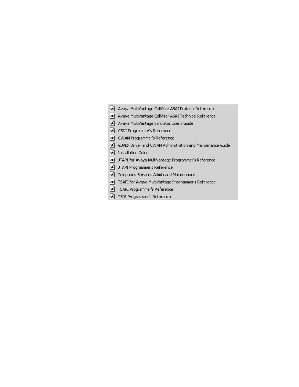
Avaya Computer Telephony Documents on Your Desktop depicts a desktop view of the
Avaya Computer Telephony documents that are provided on the Avaya Computer
Telephony CD ROM. If you elected to install the documents on your PC, you can view the
Avaya Computer Telephony document icons from your desktop (click Start, point to
Programs, Avaya Computer Telephony, Documents).
Avaya Computer Telephony Documents on Your Desktop
Related Documents
Issue 1 October 2003 17
Page 18

Preface - About This Document
Document Designations -- Icons, Titles, and File Names
The purpose of this section is to famili arize you wit h the var ious designat ions that are used
for the Avaya Computer Telephony documents. The previous section identi fies the desktop
icons for each document. This section associates those icons with the formal document
title, and the document file name. The document file name is a convenient document
handle that appears in the footer of most of the Avaya Computer Telephony documents.
Avaya Computer Telephony Document Icons, Titles and File Names
Icon Title File Name
Installation
Guide
Telephony
Services
Admin. and
Maintenance
G3PBX Driver
and CVLAN
Admin. and
Maintenance
Guide
DEFINITY
ECS
Programmer’s
Guide
Avaya
MultiVantage
Simulator
User’s Gu ide
CSDI
Programmer’s
Reference
Avaya Computer Telephony 1.3
Installation Guide
Avaya Computer Telephony 1.3
Telephony Services Administration and
Maintenance Guide
Avaya Computer Telephony 1.3
G3 PBX Driver and CVLAN Administration
and Maintenance Guide
Avaya Computer Telephony 1.3
Telephony Services Appli cation
Programming Interface (TSAPI) for
Avaya
Programmer’s Reference
Avaya Computer Telephony 1.3
Avaya MulitVantage Simulator
User’s Guide
Avaya Computer Telephony 1.3
CSTA Server Driver Interface (CSDI)
Programmer’s Reference
MulitVantage
INSTALL.PDF
NETMANGD.PDF
DEFNETM.PDF
DEFPROG.PDF
SIMGUIDE.PDF
CSDI.PDF
TSAPI
Programmer’s
Reference
TSDI
Programmer’s
Reference
CVLAN
Programmer’s
Reference
18 Installation Guide
Avaya Computer Telephony 1.3
Telephony Services Application
Programming Interface (TSAPI)
Programmer’s Reference
Avaya Computer Telephony 1.3
Telephony Services PBX Driver Interface
(TSDI)
Programmer’s Reference
Avaya Computer Telephony
CVLAN Programmer’s Reference
TSAPI.PDF
TSDI.PDF
CALLVISR.PDF
Page 19

Related Documents
Avaya Computer Telephony Document Icons, Titles and File Names (continued)
Icon Title File Name
Avaya
MultiVantage
Avaya MultiVantage CallVisor
ASAI Technical Reference
CallVisor ASAI
Technical Ref
Avaya
MultiVantage
Avaya MultiVantage CallVisor
ASAI Protocol Reference
CallVisor ASAI
Protocol Ref
JTAPI
Programmer’s
Reference
JTAPI Client
Programmer’s
Guide
Avaya Computer Telephony 1.3
Java Telephony API (JTAPI) Programmer’s
Reference
Avaya Computer Telephony 1.3
Java Telephony API (JTAPI) fo r Avaya
MultiVantage
Programmer’s Reference
Using the Avaya Computer Telephony Documents
This section presents a few possible usage scenarios to help you determine which
documents apply to your par ti cular needs.
If You are Implementing or Maintaining a DEFINITY Based TSAPI Solution
ASAITECH.PDF
ASAIPROT.PDF
JTAPI.PDF
JCLI.PDF
If you are using Avaya Computer Telephony to implement a DEFINITY-based TSAPI
solution, use the following A vaya Computer Telephony documents.
● Avaya Computer Telephony Installation Guide (INSTALL.PDF)
● Avaya Computer Telephony, Telephony Services Administration and Maintenance
Guide (NETMANGD.PDF)
● Avaya Computer Telephony G3 PBX Driver and CVLAN Administration and
Maintenance (DEFNETM.PDF)
If You are Developing a TSAPI Based Application
If you are developing a TSAPI based application, use the following documents.
● Avaya Computer Telephony Installation Guide (INSTALL.PDF)
● Avaya Computer Telephony, Avaya MultiVant age Simulator User’s Guide
(SIMGUIDE.PDF)
● Avaya Computer Telephony, Telephony Services Administration and Maintenance
(NETMANGD.PDF)
Issue 1 October 2003 19
Page 20

Preface - About This Document
● Avaya Computer Telephony G3 PBX Driver and CVLAN Administration and
Maintenance (DEFNETM.PDF)
● Avaya Computer Telephony, Telephony Services Application Programming Interface
(TSAPI) for Avaya MulitVantage (DEFPROG.PDF)
● Avaya Computer Telephony, Telephony Services Application Programming Interface
(TSAPI) (TSAPI.PDF)
If You Are Developing your own PBX Driver for Avaya Computer Telephony
If you are using the Telephony Services server and are developing your own PBX driver,
use the following documents.
● Avaya Computer Telephony Installation Guide(INSTALL.PDF)
● Avaya Computer Telephony CSTA Server Driver Interface (CSDI.PDF)
● Avaya Computer Telephony, Telephony Services Application Programming Interface
(TSAPI.PDF)
● Avaya Computer Telephony, Telephony Services PBX Driver Interface (TSDI.PDF)
If You Use CVLAN (CallVisor PC LAN) Based Applications
If you use a CVLAN based application, use the following documents.
● Avaya Computer Telephony Installation Guide (INSTALL.PDF)
● Avaya Computer Telephony CVLAN Programmer’s Reference (CALLVISR.PDF)
● Avaya MultiVantage CallVisor ASAI Technical Reference (ASAITECH.PDF)
● Avaya Computer Telephony, Telephony Services Administration and Maintenance
(NETMANGD.PDF).
● Avaya Computer Telephony G3 PBX Driver and CVLAN Administration and
Maintenance (DEFNETM.PDF)
If you are Developing JTAPI based Applications
If you are working with JTAPI based applications, use the following documents.
● Avaya Computer Telephony Installation Guide (INSTALL.PDF)
● Avaya Computer Telephony, Telephony Services Application Programming Interface
(TSAPI) for Avaya MulitVantage (DEFPROG.PDF)
● Avaya Computer Telephony Java Telephony API (JTAPI) Programmer’s Reference
(JTAPI.PDF)
● Avaya Computer Telephony Java Telephony API (JTAPI) for Avaya MultiVantage
Programmer’s Reference (JCLI.PDF)
20 Installation Guide
Page 21

Customer Support
For questions about Telephony Services, Tserver operation, or the DEFINITY G3 PBX
Driver, customers can call the National Customer Care Center at:
1 800 344 9670
Customer Support
Issue 1 October 2003 21
Page 22

Preface - About This Document
22 Installation Guide
Page 23

Chapter 1: Learning About Avaya Computer
Telephony
Use this chapter to familiarize yourself with basic Computer Telephony Integration (CTI)
concepts and the capabilities of Avaya Computer Telephony as an implementation of CTI.
This chapter contains the following sections:
● What is CTI? on page 24
● The Essential Components of a CTI System on page 26
● A Typical Avaya Computer Telephony Configuration on page 27
● Avaya Computer Telephony Components on page 29
● A Closer Look at the Essential Avaya Computer Telephony Components on page 30
● Security Issues on page 31
● Private Data and Client Applications on page 35
● Implementing a Firewall Strategy
Issue 1 October 2003 23
Page 24

Learning About Avaya Computer Telephony
What is CTI?
In simplest terms, CTI r efers to the integrati on of your tel ephone (voice) and PC application
(data) for intelligent and effec tive call processing. This integration is achieved logically, and
no physical connection is requi red between your telephone and the PC — the CTI software
performs the integration.
What is Avaya Computer Telephony?
Avaya Computer Telephony is call-center oriented Computer Telephony Integration (CTI)
software that runs on Microsoft Windows NT, Windows 2000, or Windows XP.
What Does Avaya Computer Telephony Do?
Avaya Computer Telephony acts as an enabl er of CTI applications. It pro vides appli cation s
with the ability to monitor and control resources in a telephone network, via a set of library
routines and function calls. A vay a Computer Telephony presents a pro grammatic in terfac e
that provides a common ground for computing resources to interact with switching
resources. More specifically, Avaya Computer Telephony is a telephony server that
supports multiple telephony APIs.
What APIs Does Avaya Computer Telephony Support?
Avaya Computer Telephony supports the following APIs
● Telephony Services Application Program Interface (TSAPI)
● Java Telephony Application Programming Interface (JTAPI)
● CallVisor PC
The next three sections provide more information about each API.
TSAPI
TSAPI is a telephony services API based on the ECMA (European Computer
Manufacturers Association) CSTA (Computer-Supported Telecommunication Applications)
standard.
24 Installation Guide
Page 25

JTAPI
JTAPI is a portable, object oriented API for Java-based computer telephony applications.
Through JTAPI, Java applications can access and contr o l switch resources. See Chapter
7: Using the JTAPI SDK for more information about JTAPI.
CallVisor PC
CallVisor PC is a proprietary API for applications that use the Adjunct/Switch Application
Interface (ASAI). See Chapter 5:
and CVLAN (CallVisor PC LAN).
What is CTI?
Using CVLAN for more information about CallVisor PC
Issue 1 October 2003 25
Page 26
Learning About Avaya Computer Telephony
The Essential Components of a CTI System
Although a CTI implementation c an t ake many f or ms, Figur e 1-1 depicts a simple model of
CTI in terms of Avaya Computer Telephony components. This model depicts a DEFINITY
switch that relies on the Adjunct Switch Application Interface (ASAI) to effect
communications with adjuncts ( such as the Avaya Computer Telephony server).
Figure 1-1: Essential Components of Avaya Computer Telephony — A High Level
View
Switch
DEFINITY
ECS
ASAI
Phone Line
Server
Avaya CT Server
Telephony
Services
Software
Client
TSAPI
Client
Agent
Workstation
Agent
Telephone
26 Installation Guide
Page 27

A Typical Avaya Computer Telephony Configuration
A Typical Avaya Computer Telephony Configu r ation
This section provides a high-level description of the hardware and software components
used in a typical Avaya Computer Telephony configuration.
Hardware Components in a Typical Implementation of Avaya Computer Telephony
The basic hardware components in a typic al Avaya Computer Telephony configuration are
as follows.
● DEFINITY Switch configured with ASAI
The DEFINITY switch is a device that processes calls (in coming, outgoing, and
internal) and connects them to the proper destinations.
In the context of Avaya Computer Telephony, the role of the DEFINITY switch
changes. In a Avaya Computer Telephony implementation, the DEFINITY switch
“hands off” call monit oring and c all cont rol f uncti ons to the Avaya Computer Telephony
server (or the adjunct processor). The means of effecting this handoff is the Adjunct
Switch Application Interface — ASAI.
To support Avaya Computer Telephony, the DEFINITY switch must be configured with
Adjunct Links or an ASAI Interface. DEFINITY switches that support CTI are as
follows.
- DEFINITY CSI, Si, and R (running software release G3V4 or later), Avaya
MultiVantage on a DEFI NITY Server CSI, SI, and R, and Avaya Mul tiVantage S8700
configurations
Note:
Note: G3V4 requires a field maintenance release.
- DEFINITY ONE/IP600 Release 2 (R2), or later, and Avaya MultiVantage S8100
configurations
● DEFINITY LAN Gateway
The DEFINITY LAN Gateway, or DLG, is software that acts as a transport mechanism
that allows the DEFINITY switch to co mmunicate with the Avaya Computer Telephony
server. It is required for all Avaya Computer Telephony implementations.
- DEFINITY CSI, Si, and R (running software release G3V4 or later), Avaya
MultiVantage on a DEFI NITY Server CSI, SI, and R, and Avaya Mul tiVantage S8700
configurations use a Multi-Application Platform for DEFINTY (MAPD) based DLG.
Issue 1 October 2003 27
Page 28

Learning About Avaya Computer Telephony
- DEFINITY ONE/IP600 and Avaya MultiVantage S8100 configurations use the CoResident DLG (without a MAPD board).
● Avaya Computer Telephony Server
The adjunct processor that performs call monitoring and control functions, security
database functions, and link management. Avaya Computer Telephony runs on
Windows NT, Windows 2000, or Windows XP.
● Avaya Computer Telephony Client Workstations
Client workstations run the applications that interact with the Avaya Computer
Telephony server.
28 Installation Guide
Page 29

Avaya Computer Telephony Components
Avaya Computer Telephony Components
The Avaya Computer Telephony CD ROM contains the following software components:
● Security Database for Telephony Services (Used by Telephony Services for client
authentication; it is not used by CVLAN.)
● Telephony Services Server (Tserver) Software
● Telephony Services Client Software
- Windows NT, Windows 2000, or Windows XP
- UnixWare
- Solaris S parc
- HP-UX
● CVLAN Server
● CVLAN Clients
- UNIX
- Solaris x86
- Solaris S parc
- Windows NT, Windows 2000 or Windows XP
- IBM Advanced Interactive Executive (AIX)
● DEFINITY Driver (G3 PBX Driver)
● TSAPI Software Development Kit (SDK)
● JTAPI SDK
● CVLAN SDK
● Online Avaya Computer Telephony documents and Adobe Acrobat Reader
Issue 1 October 2003 29
Page 30
Learning About Avaya Computer Telephony
A Closer Look at the Essential Avaya Computer Telephony Components
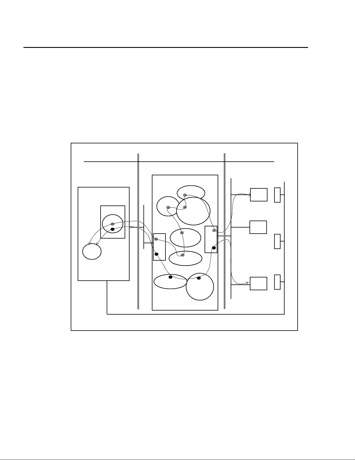
The view of Avaya Computer Telephony depicted by Figure 1-2 includes the some of the
major components described in ‘‘A Typical Avaya Computer Telephony Configuration’’ on
page 27, to give you a better sense of wher e the component s are and how they operat e at
a schematic level.
Figure 1-2: Essential Avaya Computer Telephony Components — A Closer Look
Switch
DEFINITY ECS
MAPD
DLG
ASAI
Phone Line
Server
Avaya CT Server
SDB
NIC
ASAI.DLL
CVLANCLI.DLL
TSLIB
Tserver
G3PD
CVLAN
Server
NIC
Client
TSAPI
Client
JTAPI
Client
CVLAN
Client
Phone
Phone Phone
30 Installation Guide
Page 31

Security Issues
The term security has broad connotations. In the cont ext of Avaya Computer Telephony,
security refers to toll fraud issues only. The next two sections prov ide some basic
guidelines for effecting secure, isolated LAN arrangements for DEFINITY. For more
information about security-relat ed issues, see Chapter 2 of Avaya Computer Telephony 1.3
G3 PBX Driver and CVLAN Administration and Maintenance
Security — DEFINITY Servers CSI, SI, R
and S8700 Configurations
If your Avaya Computer Telephony configuration relies on a platform that u ses the MAPD
(DEFINITY Server CSI, SI, R and S8700 Configurations) refer to Figure 1-3 as you read
this section.
Security Issues
(DEFNETM.PDF).
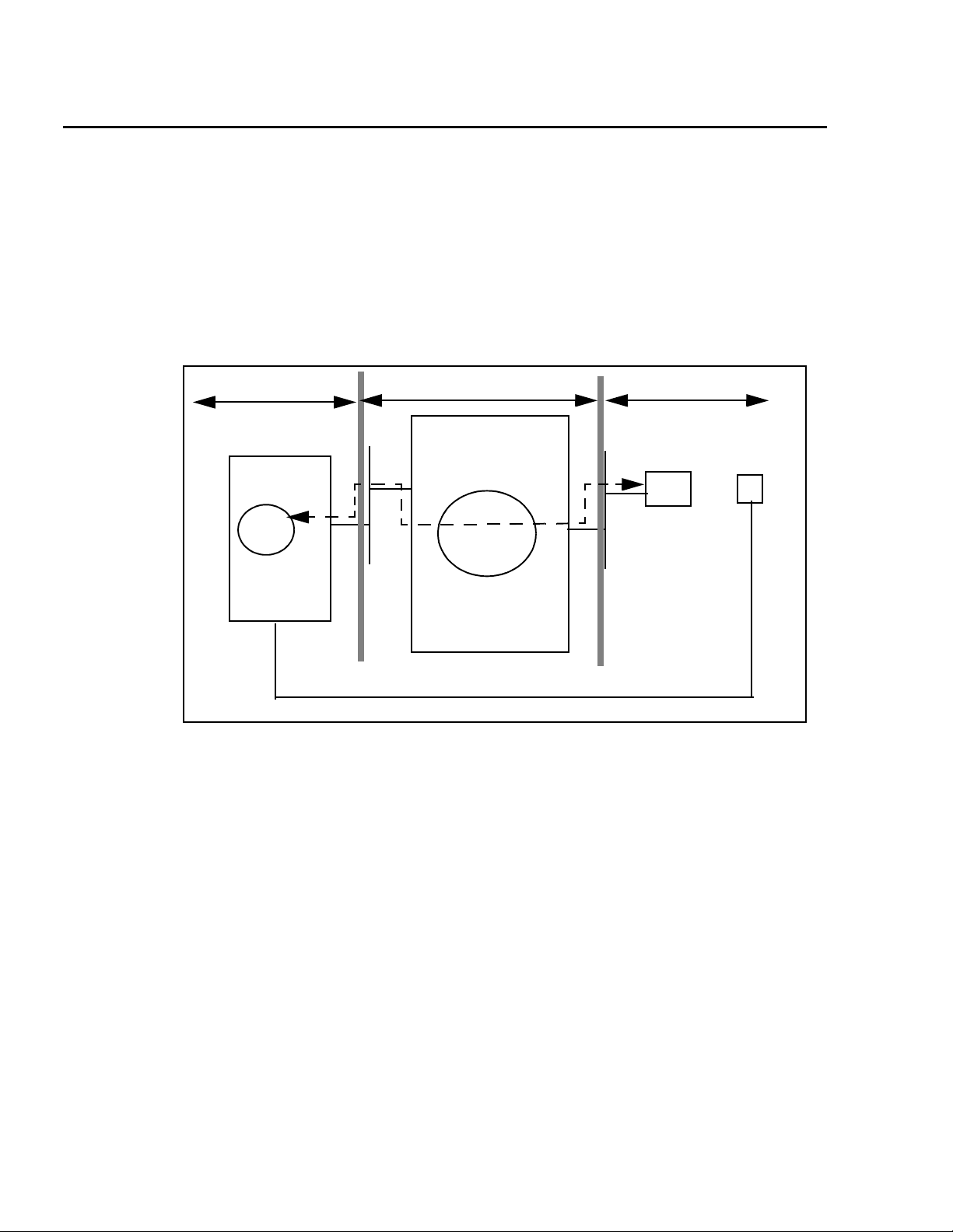
Isolating the DEFINITY LAN Gateway
The DEFINITY LAN Gateway system assembly should be on its own separate segment
and will consequently require it s o wn separate LAN card. This means you will need two
network interface cards (NICs) in your Telephony Server, one for client access and one f or
the connection between the DEFINITY G3 PBX Driver and the DEFINITY LAN Gateway
system assembly.
Follow these guidelines to ensure that the DEFINITY LAN Gateway system is not
accessible from the rest of the network.
● Use a separate secure link connecting the Telephony Server to the DEFINITY LAN
Gateway system.
● You will administer the IP address of the DEFINITY G3 PBX Driver during the
installation of the DEFINITY G3 PBX Driver. Do not administer the same IP address for
the DEFINITY G3 PBX Driver that your Telephony Server is using. If you do administer
the same IP address for both, yo u will leave your syste m open fo r possibl e toll fraud and
may receive a toll fraud warning.
● Make sure that IP forwarding (formerly referred to as IP routing) is turned off between
the DEFINITY G3 PBX Driver NIC and the NIC on the Avaya Computer Telephony
Server . After install ing the NIC on your A vaya Computer Telephony server , con figure the
connection with no IP forwarding. See “Configuring the Tserver for a Secure LAN
Gateway Connection” in Chapter 2 of Avaya Computer Telephony 1.3 G3 PBX Driver
and CVLAN Administration and Maintenance (DEFNETM.PDF).
Issue 1 October 2003 31
Page 32

Learning About Avaya Computer Telephony
!
WARNING:
WARNING: Customers who do not follow this recommendation may be subject to a
person or persons gaining illegal access to the DEFINITY LAN Gateway
application to commit toll fraud and/or tamper with the real-time aspects of
Computer Telephony Integration (CTI) applications. (Toll fraud is the
unauthorized use of your t elecommunications s ystem. Under ap plicable law,
the customer is responsible for paying for such unauthorized usage.)
Figure 1-3: DEFINITY ECS/DEFINITY Server CSI Security Guidelines
DEFINITY ECS
Ethernet
DEFINITY
LAN
Gateway
192.168.25.10
Keep the DEFINITY LAN Gateway
connections isolated from the
rest of the network.
Prohibit any routing between
the NIC used for the DEFINITY LAN
Gateway and any other NIC.
Separate LAN segm ent
Separate LAN segm e nt
Clients
Avaya CT
Server
Switch access
NIC
192.168.25.20
G3PBX
Driver
Telephony
Server
(TSRV)
NIC
176.108.25.20
Client access
32 Installation Guide
Page 33

Security Issues
Security — DEFINITY ONE/IP600and Avaya MultiVantage
S8100 Configurations
Figure 1-4 depicts two optional connection methods, a non-isolated link on the same LAN
segment and an isolated, secure link on a separate LAN segment. Be sure to review
Figure 1-4 and note the security issues and toll fraud implica ti ons. Use a separate, secure
link connecting to DEFINITY ONE/IP600 or S8100 Media Server configuration.
Figure 1-4: Connectivity Options
Connectivity via TN2314 PROCR — Non-Isolated or Same LAN segment
With this connection option,
DEFINITY ONE is not
isolated from the
rest of the network.
The client and the switch use
the same LAN segment.
DEFINITY ONE
Avaya CT
Server
Switch access
TN2314
PROCR
DLG
G3PBX
Driver
Telephony
Server
(TSRV)
Client access
NIC
Clients
Connectivity via TN799 CLAN — Isolated or Separate LAN segment
With this connection option,
the DEFINITY ONE-to-server
connection is isolated from
the rest of the network.
Clients are not on the same
LAN segment as the switch.
DEFINITY ONE
TN2314
PROCR
DLG
TN799
C-LAN
HUB
Avaya CT
Server
Switch access
NIC
G3PBX
Driver
Telephony
Server
(TSRV)
NIC
Client access
Clients
Issue 1 October 2003 33
Page 34

Learning About Avaya Computer Telephony
Implementing a Firewall Strategy
Avaya Computer Telephony supports a variety of configuration methods and addressi ng
techniques that are used in a firewall environment. The documentation presents the
information in terms of where you are setting up your firewall.
● If you are setting up a firewall between the Avaya Computer Telephony client and the
Avaya Computer Telephony Server (Tserver), see Chapter 6 of the Telephony Services
Administration and Maintenance Guide (NETMANGD.PDF).
● If you are setting up a firewall between the G3PBX driver (located on the Avaya
Computer Telephony Server) and the switch, see Chapter 2 of the G3PBX Driver and
CVLAN Administration and Maintenance Guide (DEFNETM.PDF).
Note:
Note: While Avaya Computer Telephony can support a firewall on either side of the
Tserver, it is recommended that the fire wall be placed between the Tserver
and the client rather than the Tserver and the switch.
34 Installation Guide
Page 35

Private Data and Client Applications
Private Data and Client Applications
Private Data allows Avaya Computer Telephony to take advantage of DEFINITY features.
A complete description of private data is beyond the scope of this document, but a simple
overview will help you understand how if affects your applications. At a conceptual level the
main points are as follows.
● Private data is a switch-specific software implement ation that provides value added
services. Your applications can take advantage of the private data services that are
included in the Telephony Services API.
● An application that is based on “Private Data Ver sion 5,” for example, can run on a
switch that is running “Private Dat a Version 6,” but the application is restricted to the
capabilities of Private Data Version 5. In this sense, private data version control is
transparent, or backward compatible.
● If you want your Private Data Version 5 based applications to t a ke advant age of Privat e
Data Version 6 capabilities, you must upgrade all the services your application uses to
Private Data Version 6.
For more information about private data services, see Avaya Computer Telephony,
Telephony Services Application Programming Interface (TSAPI) for Avaya MultiVantage
(DEFPROG.PDF). Table 1-1 summarizes application client platforms and private data
version compatibility.
Table 1-1: Avaya Computer Telephony Client Platforms - Private Data Version
Compatibility
Win32® Windows 95 All versions
Windows 98
Windows NT 3.5.1 workstation or server
Windows NT 4.0 workstation or server
Windows 2000 Professional or Server
Windows XP
Solaris Sparc Solaris Sparc All versions
UnixWare UnixWare 1.x, UnixW are 2.0x, UnixWare 7 All versions
HP-UX HP-UX Version 10 V5 and earlier
Java (JTAPI)
Java VM
1
All version s
Netscape Navigator® 3.x + or Internet Explorer™
4.x +
1. Any Java Virtual Machine (VM) compatible with the Sun Microsystems Java specification, Version
1.02 or later .
Issue 1 October 2003 35
Page 36

Learning About Avaya Computer Telephony
36 Installation Guide
Page 37

Chapter 2: Administering the Switch
This chapter describes DEFINITY-based tasks that must be performed to implement
communications between the DEFINITY switch and the Avaya Computer Telephony
server.
This chapter contains the following sections:
● Scope of this Chapter on page 37
● Hardware and Software Components on page 38
● Using the Information in this Chapter on page 39
● Activating Software Features — RFA and License Files on page 40
● License Files on page 40
● License File and Optional Features Forms on page 40
● Administrative Tasks for Avaya Platforms That Use the MAPD on page 41
● Administrative Tasks for Avaya Platforms That Use the Co-Resident DLG on page 53
Scope of this Chapter
Refer to Figure 2-1 as you read this section. The scope of th is chapter includes activities
associated with setting up the DEFINITY switch, administering the communications
interface to the Avaya Computer Telephony server, and establishi ng a li n k. The next
sections describes the components that are affected.
Issue 1 October 2003 37
Page 38

Administering the Switch
Hardware and Software Components
The hardware and software components rel evant in this chapter are described in this list.
● Avaya MultiVantage
Avaya call processing configurations. From the viewpoint of product names, it is part of
the name of each call processing platform.
● The DEFINITY Server, the Media Server, or the Media Gateway (such as DEFINITY
Server CSI, DEFINITY Server SI, and DEFINITY Server R, Avaya S8100 Media Server
configurations, Avaya S8300 with Avaya Media Gateway, and Avaya MultiVantage
S8700 Media Server configurations)
● DEFINITY LAN Gateway (DLG), software which can reside on the Multi-Application
Platform for DEFINITY ( MAPD) or can be Co-Resid ent with cal l MultiVantage Processor
Card. The following list describes the platforms that rely on the MAPD DLG and the
platforms that rely on the Co-Resident DLG.
● Platforms that use the TN800 series MAPD
● DEFINITY Servers (CSI, SI, and R), and Avaya MultiVantage S8700 Media Server
configurations.
TM
software — the call processing software that resides on all
● Platforms that use the Co-Resident DLG (the DLG software co-resides with
MultiVantage call proc essing on the processor card.
- Avaya S8100 Media Server configurations (formerly DEFINITY ONE and IP 600)
- Avaya S8300 Media Gateway with G700 Media Server (with an Internal Call
Controller)
Note:
Note: In some configurations, the TN2314 card (with Co-Resident DLG) relies on
the TN799 Control LAN (C-LAN) card for LAN isolation.
38 Installation Guide
Page 39

Using the Information in this Chapter
Using the Information in this Chapter
This chapter makes two basic assumptions — that you have a DEFINITY switch, with the
DEFINITY LAN Gateway (DLG) system already installed, and that you have a TCP/IP
based LAN that is capable of isolating your server-based functions from your client-based
functions.
The type of DEFINITY switch you have determines how you use this chapter.
● If you use a DEFINITY Server (CSI, SI or R) or an Avaya MultiVantage S8700 Media
Server configuration, complete the tasks described in ‘‘Administrative Tasks for Avaya
Platforms That Use the MAPD’’ on p age -41.
● If you use an Avaya Multi Vantage S8100 Server (formerly DEFINITY ONE/IP600) or an
Avaya MultiVantage S8300 Media Server with a G700 Media Gateway, complete the
tasks described in ‘‘CTI Link Administration on Configurations with Processor
Connectivity’’ on page -54
● If you use an Avaya S8100 Media Server (DEFINITY ONE/IP600) configuration with a
processor and C-LAN, see ‘‘CTI Link Administration on Configurations with CLAN
Connectivity’’ on page -56
Issue 1 October 2003 39
Page 40

Administering the Switch
Activating Software Features — RFA and License
Files
With Release 10, Avaya implemented a new a pproach to activating sof tware featur es. This
new approach relies on the Remote Feature Activ ation (RFA) process and the creation of a
License file. All activities associat ed with RFA and the generati on of license files are
carried out by Avaya support. To change software features, you wil l need to contact your
Account Executive and have a new license file generated via the RFA process.
License File s
All DEFINITY R10, and subsequent MultiVantage systems require a valid license to
operate as a switch.The License File controls following switch settings:
● software release
● offer category
● features
● capacities
Without a license file, the switch does not provide normal call processing.
License File and Optional Features Forms
Because the license file determines features and capabilities, the ASAI Optional features
that appear on the OPTIONAL FEATURES form are pre-set, or inherited from the license
file, and switch administrators cannot change them.
For example, if you type display system parameters and go to the page that lists
optional features for ASAI (typically page 2) you would see the settings that were effected
by the license file.
If your form lists ASAI Link Plus Capabilities? n, it means that your system has
not been set up with ASAI Link Plus Capabilities. You can not change the "n" to a "y" on
this form. To do so you would have to cont act your AE and make ar rangement s to have the
change implemented through RFA.
40 Installation Guide
Page 41

Administrative Tasks for Avaya Platforms That Use the MAPD
Administrative Tasks for Avaya Platforms That Use
the MAPD
This section describes administrative tasks you must complete before you can install
Avaya Computer Telephony in a configuration that uses a MAPD, such as DEFINTY
Servers (CSI, SI, and R), Avaya MultiVantage S8700 Media Server for Multi-Connect
Configurations, and Avaya Mult iVantage S8700 Media Server for IP-Connect
Configurations.
● Task 1: Administration on a DEFINITY System Administration Terminal (SA T)
● Task 2: MAPD and DLG Administration via a MAPD Administration Terminal
Once you complete these tasks, proceed with Chapter 3:
Installing Avaya Computer
Telephony Server Software.
Figure 2-1: DEFINTY Server and MAPD/DLG Administration at a Glance
DEFINITY ECS and DEFINITY
Server CSI Administration
via SAT ter minal
Task
Verify software versi o n
Verify ASAI features
1
List configuration
Administer station
DEFINITY ECS
MAPD
DLG
DLG Administration
via MAPD Administration terminal
(MAPD in “ASAI” state)
Task
2
Add a client — TCP/IP ADMINISTRATION
Administer a link — PORT ADMINISTRATION
Verify connectivity — DLG PORT/STATUS
Avaya CT Server
NIC
192.168.25.20
LOCAL HOST TABLE
DLG ADMINISTRATION
CONTROL
Clients
192.168.25.10
Issue 1 October 2003 41
Page 42

Administering the Switch
Setting Up Your LAN for Avaya Computer Telephony
This section applies to the following platforms, which rely on the MAPD-based DLG and
rely on a Telephony Server with t wo Netwo rk Int er face Card s ( NICs). If y ou are c onfi gurin g
Avaya Computer Telephony in a NA T or a firewall environment, see
Firewall Strategy on page 34.
● DEFINITY Servers CSI, SI, and R
● Avaya MultiVantage S8700 Media Server for Multi-Connect Configurations
● Avaya MultiVantage S8700 Media Server for IP-Connect Configurations
Before you administer the DEFINITY swi tch (including the DLG), make sure that you have
determined how your LAN is set up.
Server LAN Segment (connectivity to the switch)
Server LAN segment functions are in the DLG administrative domain. For serve r-to-swi tch
functions follow these guidelines.
Implementing a
● The DLG must be connected to the LAN that the Avaya Computer Telephony server
uses (the Avaya Computer Telephony server communicates with the switch via the
DEFINITY G3 PBX Driver).
● The DLG should be on its own separate LAN segment. To effect this, you will need two
Network Interface Cards ( NICs ) in the A vaya Computer Telephony Server, one for client
access and one for the connection between the DLG and the DEFINITY G3 PBX Driver .
IP Addresses
It is strongly recommended that you use at least two IP addresses.
● IP address for the DLG
● IP Address for the DEFINITY G3 PBX Driver
Make certain that you have the IP address or the DLG or its host name (if host
names are used instead of IP addresses). See the DEFINITY switch administrator.
If you are using a separate LAN for your DLG (recommended) and all links go to a
single switch, then you can use the default IP address, whi ch is 192.168.25.10.
Verify that you have a local IP address for the DEFINITY G3 PBX Driver on your
Telephony Server. You will need this IP address for inst all ing the DEFINITY G3 PBX
Driver. You may obtain this address from the network administrator or you may use
the default address provided in the inst a llat ion program (192 .168.25. 20) if you have
a private LAN (as recommended) between the Telephony Server and the DEFINITY
ECS switch. This local IP address should be different from the IP address used for
the Avaya Computer Telephony server, as recommended.
42 Installation Guide
Page 43

Administrative Tasks for Avaya Platforms That Use the MAPD
Client LAN Segment
See Chapter 4: Installing Avaya Computer Telephony TSAPI Client Software for more
information about client-based Avaya Computer Telephony requirements.
Guidelines for Setting Up a Private LAN
Follow these guidelines for implementing a privat e LAN for Avaya Computer Telephony.
Use IP addresses within the following ranges:
● 10.0.0.0 — 10.255.255.255
● 172.16.0.0 — 172.31.255.255
● 192.168.0.0 — 192.168.255.255
If You Intend to Use Host Names
You have the option of using host names, instead of I P address es, when admini steri ng the
DEFINITY LAN Gateway and the DEFINITY G3 PBX Driver. If you use host names instead
of IP addresses, each entry in the HOSTS file provides information about one host on the
IP network. The DEFINITY LAN Gateway link connection is considered a host.
Note:
Note: The DLG has a default set of administered parameters that correspond to
the defaults provided in the Avaya Computer Telephony DEFINITY G3 PBX
Driver installation. If you implement private addressing you will have to
change these settings on the G3PBX Driver Configuration Dialog Box (see
Chapter 3:
Installing Avaya Computer Telephony Server Software .)
Issue 1 October 2003 43
Page 44

Administering the Switch
Task 1: Ad m in is t e rin g a Link
This section applies to the following platforms, which rely on the MAPD-based DLG.
● DEFINITY Servers CSI, SI, and R
● Avaya MultiVantage S8700 Media Server for Multi-Connect Configurations
● Avaya MultiVantage S8700 Media Server for IP-Connect Configurations
The objective of Task 1 is administering a link. From the DEFINITY SAT , f ollow these step s
to complete Task 1.
Note:
Note: Whenever you use the change form of a DEFINITY SAT command, you
must log out for the changes to take effect.
1. Log in to the DEFINITY switch.
2. Type display system-parameters customer-options
The OPTIONAL FEATURES screen appears.
3. Check Computer Telephony Adjunct Links? and make sure it is set to y, (page
2 of the OPTIONAL FEATURES screen in the example above). This sett ing indicates
that DEFINITY is capable of communicating with an adjunct.
Note:
Note: If this field is not set to "y" then contact your Avaya Account Repres entative.
44 Installation Guide
Page 45

Administrative Tasks for Avaya Platforms That Use the MAPD
4. Type list configuration software-versions
The SOFTWARE VERSIONS screen appears.
5. Check the SOFTWARE VERSION to verify that the correct DEFINITY sof tware versi on
is running on the switch. The following versions are appropriate: G3V4, or later.
Note:
Note: G3V4 requires a field maintenance release.
6. Type list config all to determine what ports are available on the MAPD for
adding a station.
The SYSTEM CONFIGURATION screen appears.
Under Assigned Ports, each u represents an available or unassigned port.
list configuration all
Page 1
---------------------------------------------------------------------SYSTEM CONFIGURATION
Board
Number
1A01
1A02
1A03
1A04
1A05
1A06
Board Type Code Vintage Assigned Ports
EXPANSION INTF
EXPANSION INTF
RESERVED LGATE
RESERVED LGATE
MAPD BOARD
TN776
TN776
TN801
TN801
TN801
000001
000001
MAPD
MAPD
000001
u u u u u u u u
u u u u u u u u
01 u u u u u u u
u u u u u u u u
u u u u u u u u
u u u u u u u u
7. Choose a port associated with the MAPD board to add a station to the DLG (on the
MAPD).
8. Type add cti-link <n> (where n represents the link number)
The LINK screen appears.
Issue 1 October 2003 45
Page 46

Administering the Switch
9. Follow Steps a through i to add an ASAI-enabled station. Completing the LINK screen
administers an adjunct IP link between DEFINITY and a Avay a Computer Telephony
server.
a. In the Extension: type any valid extension on the dial plan (for example, 1008).
b. In the Type: field, type ADJLK
c. In the Port: field, type an available port number
d. In the Name: field, type the name of the A vaya Computer Telephony server
e. In the XID: field, accept the defaul t (n)
f. In the Fixed TEI: field, type y
g. In the MIM Support: field, accept the def ault (n)
h. In the CRV Length: field, type 2
i. In the Event Minimization: field, accept the default (n)
All other fields on the Link screen use the default values.
This completes Task 1: DEFINITY Administration. Proceed to Task 2: DLG Administration
.
46 Installation Guide
Page 47

Administrative Tasks for Avaya Platforms That Use the MAPD
Task 2: DL G Adm in istra ti on
The objective of Task 2 is to establish connectivity between DEFINITY and your Avaya
Computer Telephony server, by way of the DLG. Task 2 assumes that the DLG is already
installed and administered. For more information see DEFINITY ECS and CallVisor ASAI
Applications over MAPD (555-230-136).
From the MAPD administrative terminal, follow these steps to complete Task 2.
1. Log in to the MAPD system
The Main Menu appears.
1. Login/Password Administration
2. TCP/IP Administration...
Main Menu
If both the DLG and CVLAN
applications are on the MAPD
this Main Menu appears.
3. Port Administration... is
for access to DLG and CVLAN)
3. Port Administration...
4. Maintenance...
5. DLG Port Status/Control
6. CV/LAN Port Status/Control
7. Exit
Main Menu
If only the DLG application
is on the MAPD
this Main Menu appears.
1. Login/Password Administration
This line is used to provide abbreviated help on the currently selected field.
2. TCP/IP Administration...
3. DLG Administration
4. Maintenance...
5. DLG Port Status/Control
6. Exit
This line is used to provide abbreviated help on the currently selected field.
ENTEREXIT REFRESH HELP
ENTEREXIT REFRESH HELP
3. DLG Administration
for access to DLG.
2. From the Main Menu, select 2. TCP/IP Administration.
Issue 1 October 2003 47
Page 48

Administering the Switch
3. From the TCP/IP Administration screen select 1. This Host
The TCP/IP Administration This Host screen appears (This Host refers to the MAPD
itself).
4. Verify (or make a note of) the Host Name and IP address of the MAPD.
● The Host Name is the name that you assign to the MAPD.
● The Host IP Address is the IP address required when you perform G3 PBX Driver
link administration on the Avaya Computer Telephony Server. See Chapter
3: Installing Avaya Computer Telephony Server Software.
5. Once you have noted this information, select CANCEL to return to the Main Menu.
48 Installation Guide
Page 49

Administrative Tasks for Avaya Platforms That Use the MAPD
6. From the Main Menu, select 2. TCP/IP Administration.
The TCP/IP Administration screen appears.
TCP/IP Administration
1. This Host
2. Local Host Table
3. Network Routing Information...
4. Exit
This line is used to provide abbreviated help on the currently selected field.
ENTEREXIT REFRESH HELP
7. From the TCP/IP Administration screen select 2. Local Host Table, which
enables you to view, add, or delete hosts. The host, in this case, is the Avaya
Computer Telephony Server.
The TCP/IP Administration Local Host Table screen appears.
Issue 1 October 2003 49
Page 50

Administering the Switch
Note:
Note: If the MAPD/DLG has already been administered to accept the default IP
address of the Avaya Computer Telephony server (192.168.25. 20), and you
want to implement a default Avaya Computer Telephony configuration, ski p
Step 8a and 8b; go to Step 8c.
TCP/IP Administration
Local Host Table
IP Address
__________________________________________________________________
___________________________________________________________________________
___________________________________________________________________________
___________________________________________________________________________
___________________________________________________________________________
___________________________________________________________________________
___________________________________________________________________________
___________________________________________________________________________
___________________________________________________________________________
___________________________________________________________________________
___________________________________________________________________________
___________________________________________________________________________
___________________________________________________________________________
___________________________________________________________________________
___________________________________________________________________________
This line is used to provide abbreviated help on the currently selected field.
Host Name Aliases
ADD DELETECANCEL REFRESH NXTPG PRVPGHELP
Page
X of X
8. Follow Steps a through e to complete the Local Host Table
Note:
Note: The addressing information you use in step s 8a and 8b must be used (in t he
DEFINITY G3PBX Driver dialog box) when you install Avaya Computer
Telephony.
a. In the IP Address field, type the IP address of the G3PBX Driver on the Avaya
b. In the Host Name field, type t he name that is assigned to the Avaya Computer
c. Select ADD to save your settings.
d. Select CANCEL to return to the TCP/IP Administration Screen.
e. From the TCP/IP Administration Screen, select EXIT to return to the MAIN MENU.
50 Installation Guide
Computer Telephony server. (You can accept the default, 192.168.25.20, if you want
to effect a "default" Avaya Computer Telephony installation).
Telephony server.
Page 51

Administrative Tasks for Avaya Platforms That Use the MAPD
9. From the Main Menu, select 3. Port Administration...
The Port Administration screen appears.
Port Administration
1. Application Port Assignment
2. DLG Administration
3. CV/LAN Administration
4. Exit
This line is used to provide abbreviated help on the currently selected field.
ENTEREXIT REFRESH HELP
10. From the Port Administration screen, select 2. DLG Administration
The DLG Administration screen appears.
11. Follow steps a through c to complete the DLG Administration screen.
DLG Administration
Port
__
This line is used to provide abbreviated help on the currently selected field.
Client Name or IP Address
_________________________
___________________________ __ ___________
___________________________ __ ___________
___________________________ __ ___________
___________________________ __ ___________
___________________________ __ ___________
___________________________ __ ___________
___________________________ __ ___________
Client Link
__
Client Status
___________
ADD DELETECANCEL REFRESH UPDATEHELP
Issue 1 October 2003 51
Page 52

Administering the Switch
a. In the Port field, type the port number of the DEFINI TY stati on administered for the
link to the Avaya Computer Telephony server (see Task 1, Step 8a)
b. In the Client Name or IP Address field, type the IP address or na me assigned
to the G3PBX Driver on the A vaya Computer Telephony server. This Client Name or
IP Address refers to the IP address you used in Step 8b.
(The default is 192.168.25.20).
c. In the Client Link field, type a number from 1 to 8 for the link assigned to the
Avaya Computer Telephony server .
12. Return to the Main Menu, and from the Main Menu, select
5. DLG Port/Status Control.
The DLG Port/Status Control screen appears.
13. From the DLG Port Status/Control screen follow these steps.
DEFINITY
Port
Port
__________________________________________________________________
__________________________________________________________________
__________________________________________________________________
__________________________________________________________________
__________________________________________________________________
__________________________________________________________________
__________________________________________________________________
__________________________________________________________________
This lin e is used to provide abbr eviated help on the currently selected field.
State
TCP/IP
Connection
State
MSGPERCANCEL REFRESH UPDATE DROPHELP STATE
DLG
Service
State
Messages
to
DEFINITY
Messages
from
DEFINITY
(minutes)
a. Verify that the port number you administered in Step 11a appears under Port.
b. Verify that REACHABLE appears under TCP/IP Connection State.
This completes the DLG/MAPD administrative tasks.
Message
Period
52 Installation Guide
Page 53

Administrative Tasks for Avaya Platforms That Use the Co-Resident DLG
Administrative Tasks for Avaya Platforms That Use
the Co-Resident DLG
This section applies to the following platforms, which can use the Co-Resident DEFINTY
LAN Gateway (DLG).
● DEFINITY ONE/IP 600
● Avaya MultiVantage S8100 Media Server configurations
● Avaya MultiVantage S8300 Media Server with G700 Media Gateway
Because these platforms do not use the MAPD based DLG, there is no MAPD
Administration. Based on your configuration, use one of the following procedures to
administer a C T I lin k
● CTI Link Administration on Configurations with Processor Connectivity on page 54
● CTI Link Administration on Configurations with CLAN Connectivity on page 56 (NOTE:
This procedure is not applicable to the S8300 Media Server configuration).
Issue 1 October 2003 53
Page 54

Administering the Switch
CTI Link Administration on Configurations with Processor Connectivity
This procedure assumes that you are running the appropriate level of software. Follow
these steps from the system access terminal (SAT) to administer a CTI link (Link Type:
ADJ-IP) in a configuration that supports a Co-Resident DLG, such as DEFINITY ONE/
IP600, Avaya S8100 Media Server configurations, or an Avaya S8300 Media Server wit h
G700 Media Gateway.
Note:
Note: Italicized terms in angl e brackets denote variables, for example
<123.213.123.111>. Substitute the appropriate value for your system.
1. Type list configuration software-versions and verify that the appropriate level of
software is running (R11.00.059 or later)
2. Type display system-p arame ters customer-option s, and go t o Page 4 of 10
OPTIONAL FEATURES form.
Verify that the Processor Ethernet? option field, is set to y.
1
of the
3. Type display system-parameters customer-options and go to Page 2 of 10 of the
OPTIONAL FEATURES form.
Verify that the Co-Res DEFINITY LAN Gateway? option field, is set to y.
4. Type display system-parameters customer-options and go to page 2 of 10 of the
OPTIONAL FEATURES form.
Verify that Computer Telephony Adjunct Link is set to y.
5. Type change ip-int erfaces and go to Page 1 of 6 of t he IP INTERFACES form. Follow
Steps a thorough f.
a. In the Enable Eth Pt option field, type y
b. In the Type option field, type procr
c. In the Net Rgn option field, type 1 or the appropriate Networ k regi on
d. In the Node Name option field, type the Processor’s IP address; for example:
<123.213.123.111>
e. In the Subnet Mask option field, type the Processor’s subnet mask, for example:
<255.255.255.0>
f. In the Gateway option field, type the router’s IP address, for example
<123.213.321.110>
6. Type change node-names. (You are on Page 1 of 1 on the IP NODE NAMES form.)
a. In the Name option field, type <the TServer’s Hostname>
1 Page numbering is relative on the OPTIONS form. The total page count is affected by the options your
system is configured with. For example, if you have ASAI Core but neither ASAI Plus nor Computer
Telephony Adjunct Links, your total page count diminishes by one (4 of 9 instead of 4 of 10).
54 Installation Guide
Page 55

Administrative Tasks for Avaya Platforms That Use the Co-Resident DLG
b. In the IP Address option field, type <t he TSe rver’s IP Address>
7. type add cti link <n> (substitute with the appropriate li nk number)
a. In the Extension field, type <station extension>
b. In the Type field, type ADJ-IP
c. In the Name field, type <name of the TServer>
8. type change ip-services
a. In the Service Type field, type DLG
b. In the Enabled field, type y
c. In the Local Node field, type procr
d. In the Local Port field, type 5678
9. After completing the IP-Services For m (Step 9), continue on to the DLG Administrat ion
form.
a. In the CTI Link field, type <n> (substitute with the appropriate link number)
b. In the Enabled field, type y
c. In the Client Name field, type <TServer’s node name>
d. In the Client Link field, type <TServer’s Link Number>
10. Type status dlg cti-link, and on the DLG CTI LINK STATUS form, verify that the
Service State field displays established.
Issue 1 October 2003 55
Page 56

Administering the Switch
CTI Link Administration on Configurations with CLAN Connectivity
This procedure assumes that you are running the appropriate level of software. Follow
these steps from the system access terminal (SAT) to administer a CTI link (Link Type:
ADJ-IP) in a configuration that supports a Co-Resident DLG.
Note:
Note: This procedure applies only to DEFINITY ONE/IP600 and Avaya S8100
Media Server configurations. It does not apply to S8300 Media Server
configurations.
1. Type list configuration software-versions and verify that the appropriate level of
software is running (R11.00.059 or later)
2. Type display system-p arame ters customer-option s, and go t o Page 4 of 10
OPTIONAL FEATURES form.
Verify that the Processor Ethernet? option field, is set to y.
3. Type display system-parameters customer-options and go to Page 2 of 10 of the
OPTIONAL FEATURES form.
Verify that the Co-Res DEFINITY LAN Gateway? option field, is set to y.
1
of the
4. Type display system-parameters customer-options and go to page 2 of 10 of the
OPTIONAL FEATURES form.
Verify that Computer Telephony Adjunct Link is set to y.
5. Type change ip-int erfaces and go to Page 1 of 6 of t he IP INTERFACES form. Follow
Steps a thorough f.
a. In the Enable Eth Pt option field, type y
b. In the Type option field, type c-lan
c. In the Net Rgn option field, type 1 or the appropriate Networ k regi on
d. In the Node Name option field, type the <C- LAN’s Node Name>
e. In the Subnet Mask option field, type the <C-LAN’s Subnet Mask>
f. In the Gateway option field, type the <Router’s IP address>
6. Type change node-names. (You are on Page 1 of 1 on the IP NODE NAMES form.)
a. In the Name option field, type <the TServer’s Hostname>
b. In the IP Address option field, type <t he TSe rver’s IP Address>
7. Type add data-module <nnnnn> (substitute with the appropriate extension number)
a. In the Type field, type ethernet
1 Page numbering is relative on the OPTIONS form. The total page count is affected by the options your
system is configured with. For example, if you have ASAI Core but neither ASAI Plus nor Computer
Telephony Adjunct Links, your total page count diminishes by one (4 of 9 instead of 4 of 10).
56 Installation Guide
Page 57

Administrative Tasks for Avaya Platforms That Use the Co-Resident DLG
b. In the Port field, type <the slot number of the C-LAN Board and add port 17>
(Example: 01a0317
)
c. In the Link option field, type 1
d. In the Name field, type <the TServer’s Hostname
8. Type add cti-link <n>
a. In the Extension field, type <station extension>
b. In the Type field, type ADJ-IP
c. In the Name field, type <name of the TServer>
9. type change ip-services
a. In the Service Type field, type DLG
b. In the Enabled field, type y
c. In the Local Node field, type clan
d. In the Local Port field, type 5678
10. After completing the IP-Services For m (Step 9), continue on to the DLG Administrat ion
form.
a. In the CTI Link field, type <n> (substitute with the appropriate link number)
b. In the Enabled field, type y
c. In the Client Name field, type <TServer’s Hostname>
d. In the Client Link field, type <TServer’s Link Number>
11. Type sta tus dlg cti-link, and on the DLG CTI LINK STATUS form, verify that the
Service State field displays established.
Issue 1 October 2003 57
Page 58

Administering the Switch
58 Installation Guide
Page 59

Chapter 3: Installing Avaya Computer
Telephony Server Software
This chapter includes the following secti ons and focuses on the activities associated with
installing the Avaya Computer Telephony Server software components.
● Planning Your Installation on page 60
● Guidelines for Upgrading Avaya Computer Telephony on page 64
● Specialized Install ations on page 66
● Before You Install the Avaya Computer Telephony Server Software on page 67
● Avaya Computer Telephony Installation Guidelines on page 68
● Procedure for Initial, Default Installation of Avaya Computer Telephony Server
Software on page 70
● Perform Initial Restart on page 85
● Basic Maintenance Tasks on page 87
Issue 1 October 2003 59
Page 60

Installing Avaya Computer Telephony Server Software
Planning Your Installation
Installing the Avaya Computer Telephony software represents a continuation of the switchspecific activities descri bed in Chapter 2. Planning your installation represents the
transition from Phase 1 to Phase 2 (see Fig ure 3- 1). Dur i ng this s t age, the activi t ies are as
follows:
● Gather the necessary information
● Determine the requirements of your configuration
- If you are installing A vaya Computer Telephony in a NAT or a Firewall environment ,
Implementing a Firewall Strategy on page 34
see
● Determine the type of install ation — initial Insta llation or upgrade
● Make sure your platform can support Avaya Computer Telephony
Each of these activities is described in the next part of this chapter.
Figure 3-1: “CTI — Planning Your Server Installation”
Computer T elephony Integration
Phase 1 Phase 2
TASK 1
Administer
DEFINITY
TASK 2
Administer
DLG
Phase 2 involves gathering host names or IP addresses:
the DLG (on the MAPD)
the NIC on the Avaya CT Server that communicates with the DLG
the NIC on the Avaya CT Server that communicates with clients
DEFINITY
MAPD
DLG
192.168.25.10
Install
Avaya CT
Server Software
S
Avaya CT Server
NIC
192.168.25.20
NIC
Phase 3
Install
Client
Software
Clients
60 Installation Guide
176.108.25.20
Page 61

Gather the Necessary Information
The TCP/IP addressing information that is administered during DLG administration is
particularly relevant to installing the Telephony Services software (see
Administration on page 47). Make sure you have the following addressing information
before you start the Avaya Computer Telephony server software installation procedure.
● The IP address of the DLG. The default is 192.168.25.10, but it is highly likely that this
has been changed to conform to your network addressing requirements.
● The IP address that the DLG administrator assigned to the Avaya Computer Telephony
server. The default is 192.168.25.20. Again, it is highly likely that this IP address has
been changed to conform to your network addressing requirements. This IP address
refers to the Network Interface Card, on the Avaya Computer Telephony Server, that
communicates with the DLG. It is not the IP a ddres s of t he NIC, o n t he A vaya Computer
Telephony server, that communicates with clients.
● The host name or IP address that was assigned to the Avaya Computer Telephony
server.
Determine the Requirements of Your Configuration
Planning Your Installation
Task 2: DLG
Determining the requirements of your configuration involves identifying the Avaya
Computer Telephony software components you are going to implement. Basically this
comes down to one question: “does this configuration support bot h the Tserver (Telephony
Services Server) and the CVLAN (CallVisor PC Local Area Network) applications?" See
Chapter 5:
Using CVLAN for information about CVLAN.
Determine the Type of Installation -- Initial Installation or Upgrade
If you are upgrading an earlier release of Avaya Compu ter Telephony, see Guideli nes for
Upgrading Avaya Computer Telephony on page 64.
Make Sure Your Platform Can Support Avaya Computer Telephony
See Table 3-1: Server Hardware on page 62 and Table 3-2: Server Software on page 63
to make sure that you have the appropriate hardware and software.
Issue 1 October 2003 61
Page 62

Installing Avaya Computer Telephony Server Software
Avaya Computer Telephony Hardware and Software Requirements
Table 3-1 lists the server hardware requirements for Telephony Services and CVLAN
server which is based on Contact Center siz e (i. e numb er of Agents).
Table 3-1: Server Hardware
Low to Low MidEnd Contact
Center (10-200
Mid-End Contact
Center (200-500
Agents)
High-End Contact
Center (500-2500
Agents)
Agents)
CPU Pentium III 350MHZ
or higher
Pentium
500MHZ or higher
®
III
Pentium® III
700MHZ or higher
RAM 256MB or higher 512MB or higher 512MB or higher
Network
Connections
For a standard
installation, 2
network interface
card(s) are
recommended:
● one for the G3PD
● one for client
access
If your configuration
uses NAT or a
Firewall, see
Implementing a
Firewall Strategy on
page 34
Drives CD-ROM drive: 3.5-
inch floppy drive (for
license and
authorization disks)
For a standard
installation , 2
network interface
card(s) are
recommended:
● one for the G3PD
● one for client
access
If your configurati on
uses NAT or a
Firewall, see
Implementing a
Firewall St rategy on
page 34
CD-ROM drive: 3.5-
inch floppy drive (for
license and
authorization disks)
For a standard
installation, 2
network interface
card(s) are
recommended:
● one for the G3PD
● one for client
access
If your configuration
uses NAT or a
Firewall, s e e
Implementing a
Firewall Strategy on
page 34
CD-ROM drive: 3.5-
inch floppy drive (f or
license and
authorization disks)
Disk Space
1. Each disk sp ace requ irement i s an app roximati on. The am ount of disk sp ace requi red also depends
on other factors such as, the num be r of use r s, type s of a cti vi ty pe rform ed , and num ber an d/o r size
of the trace files.
62 Installation Guide
1
300MB Hard Drive 300MB Hard Drive 300MB Hard Drive
Page 63

Planning Your Installation
Table 3-2 lists the server software requirements for Telephony Services and CVLAN
Table 3-2: Server Software
Software Description
Operating System Any of the following:
● Windows NT 4.0 (Server is
recommended)
● Windows NT Service Pack 6a or
later, available from Microsoft
● Windows 2000 with Service Pack 2
● Windows XP
● Windows 2003
Network Software TCP/IP protocol stack
Issue 1 October 2003 63
Page 64

Installing Avaya Computer Telephony Server Software
Guidelines for Upgrading Avaya Computer Telephony
Although the installation pr ocedure in this chapter depicts an initial installation, you follow
the same basic procedure to upgrade. If you are upgrading, however, be sure to review
this section before you upgrade your Av aya Co mpu ter Telephony software.
● If you install any Service Packs or if you upgrade Windows NT, Windows 2000,
Windows XP software on a machine that already has Telephony Services software
installed, you must reinstall all of the Telephony Services software components,
including the Telephony Services Security Database (SDB).
● If you are upgrading (or migrating) from a NetWare Telephony Server to a Windows NT,
Windows 2000, Windows XP Telephony Server, see Appendix C:
Security Database.
● Uninstalling the Telephony Server software is not recommended when upgrading from
an earlier release unless t he new sof t ware wi ll be i nst al led in a d if f er ent dir ecto ry on the
server. (Information about the Telephony Server is stored in the Windows NT, Windows
2000, Windows XP Registry. These registry setti ngs are removed when the software is
uninstalled.)
Migrating your
● Stop Telephony Services and the Logging Service before you attempt to install the new
software. See Manually St opping Telephony Services
● Overwrite your previous installation of Avaya Computer Telephony. If the previous
on page 89.
installation did not use the default destination folders (C:\Program Files\Avaya\CT) for
these components, be sure to specify the destination folders that were used during the
initial installa tion. St eps 7 and 8 provide a Destination Direct ory dialog box that enables
you to browse to, and spe cify a nother des tination for A vaya Computer Telephony server
files.
64 Installation Guide
Page 65

Guidelines for Upgrading Avaya Computer Telephony
● Do not re-install the Security Dat abase for Telephony services. If you are upgrading, the
checkbox for “Security Database f o r Telephony Services” is not checked on the Server
Setup dialog box (Step 3). Setup detects the pre vious installation of the Telephony
Services Security Database (also referred to as Btrieve).
If you select this checkbox during an upgrade, Setup detects the previous installation
of Btrieve and displays a warning box indicating that you have Btrieve Workstation
v6.15 installed on this machine. In this case, you can continue with the installation —
you do not need to exit.
Other Things to Consider for an Upgrade
You can take advantage of current settings or provisions that were effected in a prior
installation.
● userIDs/accounts with administrative permis sions
At Step 12, on the Select Tserver Administrator dialog box, you can use the pulldown menu to see a list of all the user IDs/accounts with administrati ve permissions
on the Telephony Server.
- Select the default user ID/account that the Telephony Server should use when it
starts. Then click Next.
The Telephony Server administrative user ID/account that you choose here
becomes the default user ID/account for first time use of administration software
tools (i.e., Telephony Services Administrator [TSA32] and Telephony Services
Maintenance [TSM32]).
Issue 1 October 2003 65
Page 66

Installing Avaya Computer Telephony Server Software
Specialized Installations
The term specialized installations refers to effecting Avaya Computer Telephony
installations that do not require all of the Avaya Computer Telephony software
components. This section desc ri bes two kinds of specialized install a tions.
● Avaya Computer Telephony without the Telephony Services Security Database
You can elect not to install the Telephony Services Security database if you already
have a database that serves your applications’ needs. To install Avaya Computer
Telephony without the Telephony Services Security Database, make sure that the
checkbox for "Telephony Services Security Database" is unchecked (at Step 5 of the
installation procedure). If you implement an install a tion of Avaya Computer Telephony
without the Telephony Services security database, you do not have access to the
Telephony Services Administration capabilities.
● Avaya Computer Telephony without the G3PBX Driver
If you are developing soft ware applicati ons and you do not have access to a DEFI NITY
switch (and you are using the DEFINITY simulator, for example) be sure that the
checkbox for "DEFINITY G3 PBX Driver and CVLAN" is unchecked (at Step 4).
66 Installation Guide
Page 67

Before You Install the Avaya Computer Telephony Server Software
Before You Inst all the Avaya Computer Telephony
Server Software
Here are some tips for effecting a smooth, uninterrupted installation.
● Determine the IP address of the Telephony Server.
In the Enter Information dialog box (Step 11), the Setup program asks you to specify
the IP address of the server. This IP address refers to the NIC that the Tserver uses for
communicating with it s client s (as opposed to the I P address for the NIC desi gnated for
the G3 PBX Driver). To locate this IP address, use this procedure.
Click Start, point to Settings , click Control Panel, double-click Network, click
Protocols (tab), select TCP/IP Protocol, and click Properties.
● Know the locations of the install ation-specific readme files.
Readme file notifications are embedded in th e installation procedure. To avoid
disruption during installation, you can clear the checkboxes for viewi ng the readme
files. Review the readme files after installation.
- Security Database Readme file
From the Windows NT, Windows 2000 or Windows XP desktop, click Start, point to
Programs, click Btrieve Technologies Database, and double-click Btrieve
Workstation Engine Readme
- Tserver Readme file.
From the Windows NT, Windows 2000 or Windows XP desktop, click Start, point to
Programs, Avaya Computer Telephony, TS Readme
- G3PBX Driver Readme
From the Windows NT, Windows 2000 or Windows XP desktop, click Start, point to
Programs, Avaya Computer Telephony, DEFINITY G3 PBX, and click G3PBX
Driver Readme
● Have license disks (or authorization disks) for Telephony Services and the
G3PBX Driver handy. Setup prompts you for them during the installation procedure.
● Unless you are an experienced administrator, effect a default installation.
If you are an experienced administrator and you want to override the defaults, these
capabilities are available.
- The Destination Directory dialo g boxes allow you to cust omize your directory
settings. Unless you are able to effect a customized installation, accept the defaults.
- The G3PBX Driver Configuration dialog box allows you to carry out administrative
tasks.
● You can specify the DEFINITY G3PBX Driver IP address and add links.
Issue 1 October 2003 67
Page 68

Installing Avaya Computer Telephony Server Software
● If you are setting up CVLAN, you can click the ADMIN button and add CVLAN
clients. See ‘‘Adding a CVLAN Client’’ on page -128 of this document.
Alternatively, you can make G3PD changes after completin g the inst allation procedu re.
Use either G3 PBX Driver Configurati on Utility or the G3 PBX Link Change Utility. See
Chapter 2 of the Avaya Computer Telephony 1.3 G3 PBX Driver and CVLAN
Administration and Maintenance Guide (DEFNETM.PDF).
Avaya Computer Telephony Installation Guidelines
When installed in an NT Domain, Avaya Computer Telephony should be installed as an
Application Member Server. Although Avaya Computer Telephony can be installed on a
Domain Controller it is not recommended.
Avaya Computer Telephony should not be installed on a server that performs any of the
following functions;
● Print Server
● Web Server
● FTP Server
● Fax Server
● RAS Server
● Router
● Voice/Screen Call Recorder Server
● Intelligent Voice Response Server
Avaya Computer Telephony should not be i nst all ed on a ser ver t hat is r unnin g appli cations
that use a Java Virtual Machine (Microsoft, Sun, or IBM).
Avaya Computer Telephony should not be installed on a server that is running Microsoft
SQL or any other database.
Avaya Computer Telephony can be Co-Resident with the following Avaya Applicat ions/
Platforms.
● BCMSVu
● Avaya Computer Telephony Internet Solutions
● Avaya Call Service
● Avaya Interaction Center
● Avaya Enterprise Manager
● DEFINITY Anywhere
68 Installation Guide
Page 69

● Avaya Web Collaboration
● Avaya Messaging
● Avaya Unified Communication Center
Avaya Computer Telephony Installation Guidelines
Issue 1 October 2003 69
Page 70

Installing Avaya Computer Telephony Server Software
Procedure for Initial, Default Installation of Avaya Computer Telephony Server Software
Follow these steps for an initial installation Avaya Computer Telephony Server Software.
You can click Cancel or Exit at any time to exit from the Setup program.
Note:
Note: This procedure depicts the CD-ROM drive ID as D:\. Substitute D with the
appropriate letter as necessary.
1. Log on to the Windows NT, Windows 2000 or Windows XP server as a user with
administrator-equivalent per missions.
2. Insert the CD in to th e CD-ROM drive .
(When Windows NT, Windows 2000 or Windows XP is using the Explorer shell, the
Setup program runs automatically if you have not disabled the AutoRun feature).
3. (Applies only if AutoRun is disabled) Cl ick Start, then click Run. In the Run di alog box,
enter D:\WININST\SETUP.EXE (or Browse to it on the CD) to st art the Setup
program.
Setup displays the Telephony Services Setup dialog box.
70 Installation Guide
Page 71

Procedure for Initial, Default Installation of Avaya Computer Telephony Server Software
4. Click the button for Avaya Computer Telephony Software.
Setup displays the Server Setup dialog box. For an initial installati on, all server
components are selected by default.
Issue 1 October 2003 71
Page 72

Installing Avaya Computer Telephony Server Software
5. click Next to accept the default settings and continue with the inst allation.
Setup displays the message, “Installation in progress, please wait...”, followed by the
Welcome dialog box for the Telephony Services Security Database (Btrieve
Workstation Engine v6.15).
72 Installation Guide
Page 73

Procedure for Initial, Default Installation of Avaya Computer Telephony Server Software
6. Click Next to continue with the installation.
Setup displays a dialog box indicating that Setup will inst all Btrieve W orkst ation Engine
v6.15 in the default destination folder, C:\Program Files\BTI\Win32\.
7. Click Next to accept the default destination folder and continue with the inst allation.
Issue 1 October 2003 73
Page 74

Installing Avaya Computer Telephony Server Software
Setup displays the Installa tion Complete dialog box, indicating that Setup has finished
installing Btrieve on your computer.
8. Click Finish (you have finished installing Btrieve) and continue with the installation to
install Telephony Services on your computer.
74 Installation Guide
Page 75

Procedure for Initial, Default Installation of Avaya Computer Telephony Server Software
Setup displays the message, “Installation in progress, please wait...”, followed by the
Welcome dialog box for the Telephony Services Setup program.
9. Click Next to continue with the installation.
Issue 1 October 2003 75
Page 76

Installing Avaya Computer Telephony Server Software
Setup displays the Choose Destination Location di alog box indicating that Setup will
install the Telephony Services files in the default destination folder, C:\Program
Files\Avaya\CT\tsrv.
10. Click Next to accept the default destination folder and continue with the installation.
76 Installation Guide
Page 77

Procedure for Initial, Default Installation of Avaya Computer Telephony Server Software
Setup displays the IP Address Required dialog box.
11. Enter the IP address for this Telephony Server (which is the IP address of the NIC that
the Telephony Server uses for communicating with TSAPI clients), and click Next.
Note:
Note: If you are configuring the Telephony Server in a firewall environment, see
one of the following documents, based on the location of your firewall.
● If your firewall is between the client and the Avaya Computer Telephony
server, see Chapter 6 of the Telephony Services Administration and
Maintenance Guide (NETMANGD.PDF).
● f your firewall is between the Avaya Computer Telephony server and
MultiVantage, see Chapter 2 of the G3PBX Driver and CVLAN Administrat ion
and Maintenance Guide (DEFNETM.PDF).
Issue 1 October 2003 77
Page 78

Installing Avaya Computer Telephony Server Software
Setup displays the Select Tserver Administrator dialog box with the list box displ aying
Administrator.
Administrator
12. Click Next to continue with the installation.
Setup copies the files and installs the Telephony Server software (as Windows NT,
Windows 2000 or Windows XP services) and prompts you to insert the license disk.
78 Installation Guide
Page 79

Procedure for Initial, Default Installation of Avaya Computer Telephony Server Software
13. Insert the disk in the appropriate drive on the server PC, and click OK.
After copying the license file, Setup displays the InstallShield Wizard Complete dialog
box, indicating that Setup finished installing Telephony Services on your computer.
14. Click Finish (you have finished installing Telephony Services software) and continue
with the installation to install the DEFINITY G3PBX Driver on your computer.
Issue 1 October 2003 79
Page 80

Installing Avaya Computer Telephony Server Software
Setup displays the message, “Installation in progress, please wait...” f ollowed by the
Welcome dialog box for the DEFINITY G3 PBX Driver Setup. (Setup installs the
CVLAN Server during this phase of instal lation).
15. Click Next to continue with the installation.
80 Installation Guide
Page 81

Procedure for Initial, Default Installation of Avaya Computer Telephony Server Software
Setup displays the Choose Destination Location dialog box indicating that Setup will
install the G3PBX Driver in the default location, C:\Program Files\Avaya\CT\G3PD\.
16. click Next to accept the default destination folder and continue with the installation.
Issue 1 October 2003 81
Page 82

Installing Avaya Computer Telephony Server Software
Setup displays the DEFINITY G3 PBX Driver Configuration dialog box.
17. Complete the G3PBX Driver configuration box as follows,
● in the DEFINITY G3 PBX Driver IP Address field, enter the IP address of the NIC
used for communicating with the switch.
● In the Advertised Switch Name field, enter the appropr iate name for the switch yo u
are connecting to (the default name is Avaya_ECS).
● in the IP Address or Host Name field, enter the appropriate IP address for the
switch you are connecting to (this the IP address of the Ethernet interface for the
DEFINTY LAN Gateway).
Note:
Note: If you are installing Avaya Computer Telephony in a firewall environment,
where the firewall is between MultiVantage and the Avaya Computer
Telephony Server, see Chapter 2 of the G3PBX Driver and CVLAN
Administration and Maintenance Guide (DEFNETM.PDF).
82 Installation Guide
Page 83

Procedure for Initial, Default Installation of Avaya Computer Telephony Server Software
Setup displays the Review Settings dialog box with the current settings for the
installation.
18. Click Next to continue with the installation.
Setup displays the License Disk Required dialog box.
Issue 1 October 2003 83
Page 84

Installing Avaya Computer Telephony Server Software
19. Insert the DEFINITY Driver Authorization [G3PDAUTH] disk in the appropriate dr ive on
the server PC, and click OK.
After copying the G3PDAUTH file, Setup displays the fol lowing Information box,
indicating that Setup is complete.
20. Click OK to continue with the installation.
Setup displays the InstallS hield Wizard Complete dialog box.
21. Click Finish to complete the Installation of the Avaya Computer Telephony Server
software (This step stops the Setup program).
Note:
Note: Make sure you review each of the readme files associated with the
84 Installation Guide
installation. See
Before You Install the Avaya Computer Telephony Server
Software on page 67 for locations of the readme files.
Page 85

Perform Initial Restart
After instal ling the Avaya Computer Telephony software you do not have to reboot the PC.
To start using Avaya Computer Telephony server software follow these steps.
1. Click Start point to Programs, Avaya Computer Telephony, and click TS Controller .
2. From the TS Controller dialog box, click Start.
Perform Initial Restart
Issue 1 October 2003 85
Page 86

Installing Avaya Computer Telephony Server Software
Desktop Components
Figure 3-2 depicts the desktop icons provided by Avaya Computer Telephony software.
Figure 3-2: Avaya Computer Telephony Components on Your Desktop
86 Installation Guide
Page 87

Basic Maintenance Tasks
Basic Maintenance Tasks
This section describes the following basic maint enance tasks for Telephony Services:
● St arting and Stopping the Telephony Services Software
● Manually Stopping Telephony Services
● Removing Software
Starting and Stopping the Telephony Services Software
This section describes the following tasks.
● starting Telephony Services
- enabling automatic startup and recovery of telephony services
● performing manual start and enabling automatic startup and recovery
● manually stopping Telephony Services
Issue 1 October 2003 87
Page 88

Installing Avaya Computer Telephony Server Software
Starting Telephony Services
You have already encountered this procedure in the context of the installation (‘‘Perform
Initial Restart’ ’ on p age -85) . Rec all t hat when t he Telephony Services server sof t ware (the
Telephony Server, or Tserver and the CVLAN server) is initially in stalled, it is in the
“STOPPED” state and must be manually started.
Follow these steps to start the Telephony Services server.
1. Click Start, point to Programs, Avaya Computer Telephony , and click TS Controller.
2. Click Start to start Telephony Services.
Telephony Services starts the Tserver and the CVLAN server and Information box
displays.
3. Click OK to dismiss the information box and return to the Telephony Services
Controller dialog box.
On the Telephony Services controller dialog box, under “Status,” the Telephony
Services state is listed as “RUNNING.”
4. Click Close to exit the Telephony Services Controller dialog box.
This completes the procedure to manually start Telephony Services software.
88 Installation Guide
Page 89

Enabling Automatic Startup and Recovery
This procedure is an extension of the previous procedur e, ‘‘Starting Telephony Services’’
on page -88, with steps for e nabling automatic S tartup and Recovery. You are
recommended to effect automatic startup and recovery.
1. Click Start, point to Programs, Avaya Computer Telephony, and click TS Controll er.
The Tserver displays the TS Controller dialog box.
2. Under Startup, click the checkbox next to “Automatically Start Telephony Services On
Server Boot.”
3. Under Recovery, click the checkbox next to “Automatically Restart Telephony
Services.”
4. Click Close to exit the Telephony Services Cont roller dialog box.
This completes the procedure for enabling automati c startup and recovery.
Manually Stopping Telephony Services
Basic Maintenance Tasks
Follow this procedure to manually or explicitly stop Telephony Services and the CVLAN
server.
1. Click Start, point to Programs, Avaya Computer Telephony , and click TS Controller.
2. From the Telephony Services Controller dialog box, click Stop.
The Telephony Services and CVLAN server are stopped, and an Information box
displays.
3. Click OK
The operating system displays a message box that prompt s you to stop the Logging
Service.
4. Click Yes to stop the logging service.
5. From the Telephony Services Controller dialog box, click Close to exit the Telephony
Services Controller.
Issue 1 October 2003 89
Page 90

Installing Avaya Computer Telephony Server Software
Removing Software
Use the standard Windows procedure described below to remove the following server
components.
● Btrieve Workstation Engine v6.15.
● Telephony Services
Note:
Note: Before you can remove the Telephony Services server software (Tserver
and CVLAN server) you must unregister telephony services. Follow the
procedure in ‘‘Reinstalling Telephony Services Server Software’’ on p age 90 (which includes the standard Windows procedure for removing
Telephony Services).
● DEFINITY G3 PBX Driver
Procedure to Remove Programs
1. From the desktop click Start, point to Settings and click Control Panel.
2. From the Control Panel, click Add/Remove Programs.
3. Windows displays the Add/Remove Programs Properties dialog box.
4. Select the appropriate module you wish to uninstall (Avaya Computer Telephony
Services, Btrieve, or Avaya Computer Telephony ECS Driver), and click Add/Remove.
5. Windows displays the Confirm File Deletion box, asking you to confirm tha t you want to
completely remove the software program and all of its components.
6. Click Yes.
The uninstall program removes the sof tware and displa ys an Information box indicating
that the program and all of its components have been removed.
7. Click OK.
This completes the procedure to remove a soft ware program.
Reinstalling Telephony Services Server Software
If you need to reinst all the Telephony Services sof tware, i t is recommended tha t you do not
uninstall the currently i nstalled Telephony Services software before performing the
reinstallation. This is because many of the parameters used by Telephony Services are
stored in the Windows NT, Windows 2000 or Windows XP registry. When the software is
uninstalled, these p arameters are also removed.
90 Installation Guide
Page 91

Basic Maintenance Tasks
Note:
Note: Although Windows NT, Windows 2000 or Windows XP registry information is
removed when you uninstall the Telephony Services software, the log fi les
(error log file, message trace file, performance log, traffic log, and SDB log
file) are not removed. When the Telephony Server is restarted af ter
reinstallation, new log file information starts at the top of the files. Any
information previously contained in the files is overwritten with the new
information.
To reinstall the Telephony Service software, follow the step s in Pr ocedure for Initial , Default
Installation of Avaya Computer Telephony Server Software.
Issue 1 October 2003 91
Page 92

Installing Avaya Computer Telephony Server Software
92 Installation Guide
Page 93

Chapter 4: Installing Avaya Computer
Telephony TSAPI Client Software
This chapter describes inst allation related procedures for Avaya Computer Telephony,
Telephony Services Application Programming Interface (TSAPI) clients. It includes the
following topics:
● Avaya Computer Telephony Clients and Private Data Versions on page 94
● Planning Your Installation on page 94
● TSAPI Client Hardware and Software Requirements on pag e 96
● Before You Install the Avaya Computer Telephony TSAPI Client Software on page 100
● Installing the Windows Client Software on page 101
● Installing TSAPI Solaris Sparc Client Software on page 110
● Installing UnixWare Client Software on page 112
● Installing HP-UX Client Software on page 116
● Removing Telephony Services Client Software on page 119
Issue 1 October 2003 93
Page 94

Installing Avaya Computer Telephony TSAPI Client Software
Avaya Computer Telephony Clients and Private Data Versions
In the context of general information about Avaya Computer Telephony, Chapter
1: Learning About Avaya Computer Telephony provides Table 1-1 on page -35, which
associates Avaya Computer Telephony, Client Application plat for m operating systems with
the level of DEFINITY Private Data Versions that they support.
Briefly summarized, Table 1-1 on page -35 states that the A vaya Computer Telephony
Windows 32-bit client platform and the Avaya Computer Telephony UnixWare client
platform supports all versions of DEFINITY Private Data up to Private Data Version 6.
Planning Your Installation
Installing the Avaya Computer Telephony TSAPI client software represents a continuation
of the server-specific activities described in Chapter 3. Planning your installation
represents the transi tion f rom Phas e 2 to Phase 3 ( see Figur e 4-1 ). During t his transi tional
state, the activities are as follows.
● Make sure that your client workstations can support Avaya Computer Telephony (see
‘‘Avaya Computer Telephony Client Hardware and Software Requirements’’ on page -
96)
● Determine if this is an upgrade or an initial installation
● Determine how you intend to distribute the software
- CD-ROM
- Network Drive
Each of these activities is described in the next part of this chapter.
94 Installation Guide
Page 95

Planning Your Installation
Figure 4-1: The CTI Continuum — Planning Your Client Installation
Computer Telephony Integration
TASK 1
Administer
DEFINITY
DEFINITY
Phase 1 Phase 2
TASK 2
Administer
DLG
MAPD
DLG
192.168.25.10
Install
Avaya CT Server
Software
Avaya CT Server
NIC
192.168.25.20
176.108.25.20
NIC
Phase 3
Install
Client
Software
Client
Administrative
Workstation
Client
Basic
Workstation
Client
Basic
Workstation
Issue 1 October 2003 95
Page 96

Installing Avaya Computer Telephony TSAPI Client Software
TSAPI Client Hardware and Software Requirements
Tables 4-1 and 4-2 list the TSAPI client hardware and software requirements.
Avaya Computer Telephony Client Hardware and Software Requirements
Table 4-1: Windows-Based Client Hardware and Software Requirements
CPU 486 or Pentium recommended
RAM Windows 95
8 MB required; 16 MB recommended
Windows NT, Windows 2000, Windows XP or
Windows 98
16 MB required; 24-32 MB recommended
Free Memory Installing and running Telephony Services and
CVLAN on a Windows client requires 500 KB of
free memory.
Disk Space 500 KB of disk space is required, or 1.5 MB if the
Telephony Services Administration software is
also installed.
Win32 Client
Platform
Operating
Systems
(The Win32 client
platform operating
systems (i.e.,
Windows 95,
Windows 98,
Windows NT,
Windows 2000,
Windows XP
)
Win32 clients:
Windows 95
Microsoft TCP/IP or equivalent 32-bit Winsock
TCP/IP transport provider
Windows 98
Microsoft TCP/IP or equivalent 32-bit Winsock
TCP/IP transport provider
Windows NT
Windows NT 3.51 or 4.0 (Workst ation or Ser ver);
Microsoft TCP/IP or equivalent 32-bit Winsock
TCP/IP transport provider
Windows 2000
Windows XP
96 Installation Guide
Page 97

TSAPI Client Hardware and Software Requirements
UnixWare Client Hardware and Software Requirements
Table 4-2: UnixWare Client Hardware and Software Requirements
CPU 386 or higher required; 486 or Pentium
recommended
RAM UnixWare Personal Edition
8 MB required
UnixWare Applic ation Server
12 MB required
Disk Sp ace 300 KB
Operating
Systems
UnixWare 1.x
UnixWare 2.0x
HP-UX Client Hardware and Software Requirements
Table 4-3: HP-UX Client Hardware and Software Requirements
CPU HP 9000 Series 700 or Series 800 machine
RAM 32 Mbytes required
Disk Sp ace 1 Mbyte
Operating
System
HP-UX
TSAPI Solaris Client Hardware and Software Requirements
Table 4-4: TSAPI Solaris Client Hardware and Software Requirements
Disk Sp ace 1.2 MB
Processor SPARC
Operating
Systems
Solaris 2.5.1, Solaris 8
Issue 1 October 2003 97
Page 98

Installing Avaya Computer Telephony TSAPI Client Software
Telephony Services Client Software
Telephony Services client software for Wind ows consists of the following componen ts. (For
information about CVLAN clients, see Chapter 5:
● Telephony Services client software — allows TSAPI applications to communicate with
the Telephony Server.
● Client administration software — enables the system administrator to perform specific
tasks. The Win32 client software includes administration and maintenance software for
the Telephony Server. The Win32 software also includes operation, administration, and
maintenance software for the DEFINITY G3 PBX Driver.
● DEFINITY G3 private data support libraries — allow TSAPI applications to take
advantage of DEFINITY G3-specific driver features that are available through private
data and escape services. This sof tware is installed automatica ll y as part of the client
installation procedure.
Once you have installed Telephony Services software on your client, yo u can easily acces s
the Telephony Services applications by creating a shortcut icon for each appl ication. (Use
the “Create Shortcut icon” feature of Windows NT, Windows 2000, Windows XP, Windows
95, or Windows 98 to create the icons. Refer to your Windows document ation for details.)
Using CVLAN.)
Telephony Services Client Platforms
The Telephony Services client software can be installed on the following client platforms:
● Windows NT 3.51 workstation or server, Windows NT 4.0 workstation or server,
Windows 2000, Windows XP, Windows 95 or Windows 98.
- 32-bit (Win32) TSAPI appli cation s use the 32-bit Telephony Services cli ent so f tware .
● UnixWare — The UnixWare client software comes in single-threaded (UnixWare 1.x)
and multi-threaded (UnixWare 2.0x) versions. For details on using the Link Status
command, see the “Link Status Command” section in Chapter 3 of Avaya Computer
Telephony 1.3 G3 PBX Driver and CVLAN Administration and Maintenance
(DEFNETM.PDF).
● Solaris Sparc - The Solaris client sof tware can be installed on a Solaris SPARC client
workstation.
● HP-UX - The HP-UX client software can be installed on a client PC.
98 Installation Guide
Page 99

TSAPI Client Hardware and Software Requirements
Client Administratio n So ftware Compon en ts
The Telephony Services client software includes Windows based administrative software
that allows the system administrator to maintain and operate the system. Follow these
guidelines before you install the client software:
● Identify the system administrat o r’s workstation. You will need to install the Windows-
based administrative software on an appropriate client workstation.
● Determine how you intend to distribute and install the client software (CD-ROM, disk,
and, if applicable, from the network server ).
Client Administration Workstation
You can assign the PC designated as the Telephony Services server as the Administrative
Client workstation, or you can use a separate workstation on your LAN.
The client software includ es the following applications that enable the system administrator
to perform specific tasks:
● Telephony Services Administrator (TSA32) is the client-based 32-bit Windows NT,
Windows 2000, Windows XP, Windows 95 or Windows 98 application that allows the
system administrator to enter info rmation for the SDB. The 32-bit Tserver maintenance
and status operations are accessed thr ough the TSM32.
● Telephony Services Maintenance (TSM32) is the client-based 32-bit Windows NT,
Windows 2000, Windows XP, Windows 95, or Windows 98 application that allows the
system administrator to view and modify maintenance and status parameters (such as
Error Logging, Message Tracing, or Tlink Information).
● DEFINITY G3 PBX Driver Administrator utility is a client-based 32-bit Windows NT,
Windows 2000, Windows XP application that provides main tenance commands that ar e
particularly useful if there are communications problems betwe en the server and the
DEFINITY LAN Gateway. This utility can be used to perform G3PD OA&M tasks for the
Tserver. It does not apply to CVLAN.
Issue 1 October 2003 99
Page 100

Installing Avaya Computer Telephony TSAPI Client Software
Before You Install the Avaya Computer Telephon y TSAPI Client Soft ware
Be sure to read this section before you run the Setup program to install the Avaya
Computer Telephony TSAPI Client Software.
● Obtain the IP address or Host Name of the Telephony Server
In the TCP/IP Name Server dialog box, the Setup program asks you to specify the IP
address of the server.
● Review the Readme file
The Client Readme file contai ns inf ormation y ou may need before i nst al ling Telephony
Services on your client. It is located on the Avaya Computer Telephony CD-ROM as
follows: <DriveID>:\Readme s\Client Readme.txt
Note:
Note: The Setup program installs the Client Readme file as follows:
C:\Program Files\Avaya\ CT\TS Win32\Client Readme.txt
100 Installation Guide
 Loading...