

Page 1

ROUTER
HARDWARE / SOFTWARE
COMPATIBILITY MATRIX
VME - BN - 5000 ROUTER - AFN -
AN - ASN - ARN - SN - V15K
VERSION 5.7
October 26, 2000
A copy printed from the file server is an uncontrolled copy. The copy holder is responsible for
verifying the document’s current revision and removing obsolete documents from point of use.
Page 2

Revision History
VERSION WRITTEN BY DATE DESCRIPTION
-Added “SN” to document title
5.0 Mike Larj 06/24/97
5.1 Mike Larj 08/11/97
5.2 Mike Larj 12/05/97
5.3 Mike Larj 10/16/98
5.4 Mike Larj 06/10/1999
5.5 J. Peter Iacobucci 09/13/1999
-Added reference to Switch Node products to intro./instruction page.
-Added CSU/DSU info to Access Node matrix
-Added CSU/DSU info to BayStack Access Node matrices
-Moved BayStack Access Node Optional Add-on Adapter Module info into
a separate matrix
-Added respin part number 112001-B to the AG2111007 info rows.
-Changed ARN products minimum software from V11.0 to V11.0/4N
-Added DCM info to ARN matrix
-Added field upgrade order numbers to ARN matrix
-Added QMCT1 w/DS0A information
-Changed part number of AN & ANH-8 N11 DCM adapter
-Added Switch Node information matrix
-Added information for DC3611014 Switch Node Module
-Added Note (2) to Switch Node information matrix
-Changed name of “Switch Node” products to “Accelar 100”.
-Added HSSI info to Access Stack Node and 5000 Router matrices.
-Changed “BNX” to “BayStream”
-Added field upgrade/spare order numbers to Access Stack Node matrix
-Changes Access Stack Node matrix to reflect country specific base units
- Changed cover sheet to reflect new corporate image.
- Added Year 2000 compliance software support statement to intro./
instruction page.
- Removed “7.60 & Above Support” option column 1 and replaced it with
“Year 2000 Compliance” option column 1.
- Added “Year 2000 Compliance” information to all product matrices.
- Removed “Current Release” status from Model# 30004, 34004/34004-S,
AD1233004, AD1233006, AD1233008, AD1304006, AD1304007,
AE1001006, AE1001010, AE1001014, AE1001038, AE1001042,
AE1101002, AE1101006, CV1001002, DC36xxxxx.
- Changed ASN2 Base Units "ID" from 1024 to 1025.
- Added Note(2) to Access Node information matrix.
- Added notes to various pages stating that VME and AFN products are not
supported in software V12.10 and higher.
- Removed Madge1 and Madge2 Fastmac+ option columns and minimum
revision information.
- Added AG1304014 - 64MB ARE information.
- Added CL1304006 & CL1304007 5782 ATM VNR Module information.
- Added FRE2-060E processor board information.
- Added AN, ANH-8, BayStack AN, BayStack ANH-8 and ARN T1/FT1
and E1/FE1 Adapter Module information.
- Added ARN 10/100-TX, 100-FX, and -48VDC Base Unit information.
- Added ARN X.25 PAD information.
- Added ISDN S/T - CSU/DSU interoperability note to ARN information
matrix.
- Added Versalar 15000 (V15K) to title page, page headers, and
introduction / instruction page. Added V15K information matrix.
- Added reference to 32MB Flash Cards to the intro. / instruction page.
- Added CV0004026/CV0011042 & CV0004027/CV0011043 ARN
E7S/7S PDB information.
- Added ARN Ethernet Motherboard respin part numbers.
- Changed ARN ISDN S/T minimum revision to 09 for interoperability
with a CSU/DSU in the same unit.
- Separated ARN matrix into two sections - Base units and modules.
- Added "S/T" to the AN and ASN ISDN SDB descriptions.
- Added Compression Daughter ID numbers to FRE2-060E information.
- Added FRE4-PPC and 4 Link modules information.
- Added Note(9) to Access Stack Node information matrix.
-Added Baystream software version 7.40
Page 3

VERSION WRITTEN BY DATE DESCRIPTION
5.6
J. Peter Iacobucci 07/25/2000
5.7 J. Peter Iacobucci 10/26/2000
- Added new V15K (BAC2) entries
- Changes to FRE4
-Modify compatibility requirements for FRE1.
FRE1 is not supported in version 12.10 or higher.
Page 4

This document is for use in identifying minimum revision requirements of systems. It is broken into three matrix sets,
each based on a reference set of products.
The first matrix, Minimum Board Requirements, is used to identify the minimum board revision for compatibility
with the various processor boards, or selected options, pertaining to the VME and BN product platforms.
The second matrix, Minimum Processor and Software Requirements, supplies the minimum processor
requirements for any module as well as the required software, also pertaining to the VME and BN product platforms.
The third group of matrices describe minimum requirements for the Access product lines (AFN, AN, BayStack AN,
ASN and ARN), 5000 Router modules, Switch Node (Accelar 100), and Versalar 15000 products.
To identify the minimum required revision for any board or Access product, select the model number from the list and
read across for the particular category requirements. The categories for the matrices are defined as follows:
CR : Current Shipping release - * indicates part numbers currently shipping from manufacturing.
Minimum Support Revision: This is Nortel Networks’ minimum supported revision. Nortel Networks strongly
recommends that, to avoid potential problems, customers should upgrade boards that are below this level.
FRE/FRE-2/FRE-2 060/FRE-2 060E/ACE 020/ACE 030: The minimum board revision level required to function
with each of these processor boards.
Options: The minimum revision required to function with each of the various optional functionality. A blank space in
these columns indicates that the optional functionality does not apply to that particular module. The functional revisions
defined in the options fields are:
Year 2000 Compliance: Required to support software that is Year 2000 compliant. Year 2000 compliance is formally
supported in Router Software V11.03 (Site Manager 5.03), as well as Router Software V12.0 Rev2 (Site Manager 6.0
Rev2) and higher. Year 2000 compliance is also formally supported in BayStream Software V7.1 Rev4.
Dial-up Services: Required to use dial backup, dial on demand, V25 bis and raise DTR (V7.60 and above feature).
Hot Swap: Ability to reliably hot swap board, also requires V7.60 or higher software for VME applications.
4MB Series 2 Flash Memory Card Support: Ability to support the 4MB Flash Memory cards. These are
recommended for, and are only supported by, software version V8.0 and higher.
8MB, 16MB and 32MB Flash Memory cards require minimum V9.0 Router Software on all platforms.
BayStream Support: Required for running BayStream (BNX) Switch software.
Programmable Memory Support: Allows reallocating a processor’s available local and global memory resources
(V7.70 and above feature).
Important: When adding a module to a node there are three checks that are required.
1. Use the Minimum Board Requirements Matrix to verify that the module is at the minimum revision for the associated
processor and any required options. Read across from the module description.
2. Use the Minimum Processor and Software Requirements Matrix to verify that the associated processor is at least the
minimum revision for that card. Read down from processor description.
3. Use the Minimum Processor and Software Requirements Matrix to verify that the correct minimum software is
running in the node. Read across from module description.
Note:
Since a Model Number and Module ID can be identical for as many as three different unique part numbers, a clear
determination of which revision is required for a given board may not easily be accomplished by electronic means. In
these cases it may be necessary to remove the board from the router to visually determine the part number.
Page 5
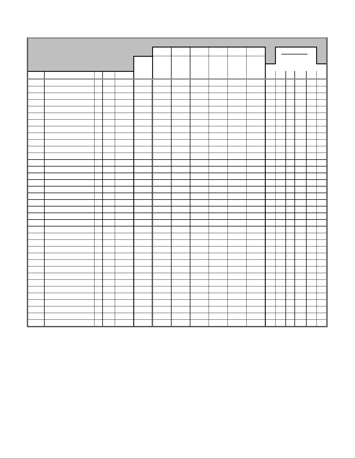
FRE-2 060E
MINIMUM BOARD REQUIREMENTS
READ ACROSS for minimum board revision
Order#
5000
5003
5008
5010
5010
5100
5118
5118
5120
5120
5121
5121
5124
5124
5200
5200
5201
5210
5220
5221
5250
5280
5280
5280
5295
5300
5405
5410
5410
5410
5410
5420
5420
5420
5420
5430
5430
Description
Syscon (4)
Syscon II (7)
Octal Sync
Sys I/O (7)
Sys I/O (7)
Enet 1 (7)
ACE 020 (1)
ACE 020 (1)
ACE 030 (7)
ACE 030 (7)
ACE 030 - 8 MEG (7)
ACE 030 - 8 MEG (7)
ACE 030 - 16 MEG (7)
ACE 030 - 16 MEG (7)
T1 II Dual
Dual T1 (1)
T1 II 56K
CSU
T1 II Single Port
T1 56K single
E1 75 Ohm
Qsync II
Qsync X
Qsync 4
HSSI
Qsync1 (7)
ENET II
SSE (7)
SSE X
SSE 4
SSE2
DSE 2 (7)
DSE X (7)
DSE 4 (7)
DSE 3 (7)
DSDE (7)
DSDE X (7)
OPTIONS KEY: 1 = Year 2000 Compliance, 2 = Dial-up Services, 3 = Hot swap, 4 = 4MB Series 2 Flash Memory Card Support,
5 = BayStream Support, 6 = Programmable Memory Support.
NOTES:
N/S = Not Supported. Blank = Not Applicable. * = Current release.
(1) = Not supported in software V8.0 and higher.
(2) = Minimum software V7.80 required.
(3) = Refers to units shipping from the factory. The required code is flash based and field updateable.
(4) = Not supported in software V8.10 and higher.
(5) = Global memory size limited to 4MB if running in a unit with ACE 020 processors.
(6) = Revision 10 is recommended if used in high data traffic BNX software applications.
(7) = VME based products are not supported in software V12.10 and higher.
CR
*
*
*
*
ID
1
7
4352
48
49
1
3
3
4
4
4
4
4
4
56
24
57
58
60
61
80
80
80
225
16
8
32
118
118
118
32
116
116
116
112
112
FRE FRE-2 FRE-2 060
Minimum 75150 75151 74027-16
Support 75153 74027-32
Part # Revision
100007
106523
109871
100013
102937
100003
101195
102330
101913
103874
106727
107030
107350
107352
100831
100009
101667
100005
101338
103496
101337
100869
101924
102285
104932
100011
100809
101053
102213
102296
101949
100860
102210
102293
101945
100929
101867
30
3
1
13
1
7
19
23
33
36
36
33
43
43
11
17
4
8
4
1
6
2
1
2
6
14
3
11
1
3
1
11
1
3
1
3
1
- - - - 30 30 N/S
- - - - 3 3 3 6 (3)
1 1 1 1 N/S N/S 1 1 1 1
- - - - 13 13 13
- - - - 1 1 1
N/S N/S N/S N/S 7 7 N/S 11
- - - - 19 19 N/S
- - - - 23 23 N/S
- - - - 33 33 33 39 43
- - - - 36 36 36 39 43
- - - - 36 36 36 39
- - - - 33 33 33 39
- - - - 43 43 43 43
- - - - 43 43 43 43
11 11 N/S N/S 11 18 11 16
N/S N/S N/S N/S 17 N/S N/S 20
4 4 N/S N/S 4 18 4 10
8 8 N/S N/S 8 8 8 14
4 N/S N/S N/S 4 18 4 10
1 N/S N/S N/S 1 18 1 6
6 6 N/S N/S 6 18 6 10
2 2 2 2 2 2 2 8 7 2
1 1 1 2 1 1 1 3 2 1
2 2 2 2 2 2 2 11 10 2
6 6 6 N/S N/S 6 (2) 6 1 7 (6)
N/S N/S N/S N/S 14 14 N/S 17
5 N/S N/S N/S 3 5 3 15
N/S N/S N/S N/S 11 11 N/S
1 1 1 N/S 1 1 1 4 3 1
3 3 3 N/S 3 3 3 12 11 3
1 1 1 N/S 1 1 1 6 5 1
N/S N/S N/S N/S 11 11 N/S
N/S N/S N/S N/S 1 1 1 4 3
N/S N/S N/S N/S 3 3 3 11 12
N/S N/S N/S N/S 1 1 1 6 5
N/S N/S N/S N/S 3 3 3 14 13
N/S N/S N/S N/S 1 1 1 4 3
75157
AG0011021
AG0011022
AG0011023
AG0011003 AG0011026
AG0011025
AG0011027
ACE 020
ACE 030
(1)
5110 5120
5118 5121
5124
(7)
1 2 3 4 5 6
OPTIONS
43 (5)
43 (5)
43 (5)
43 (5)
Page 6
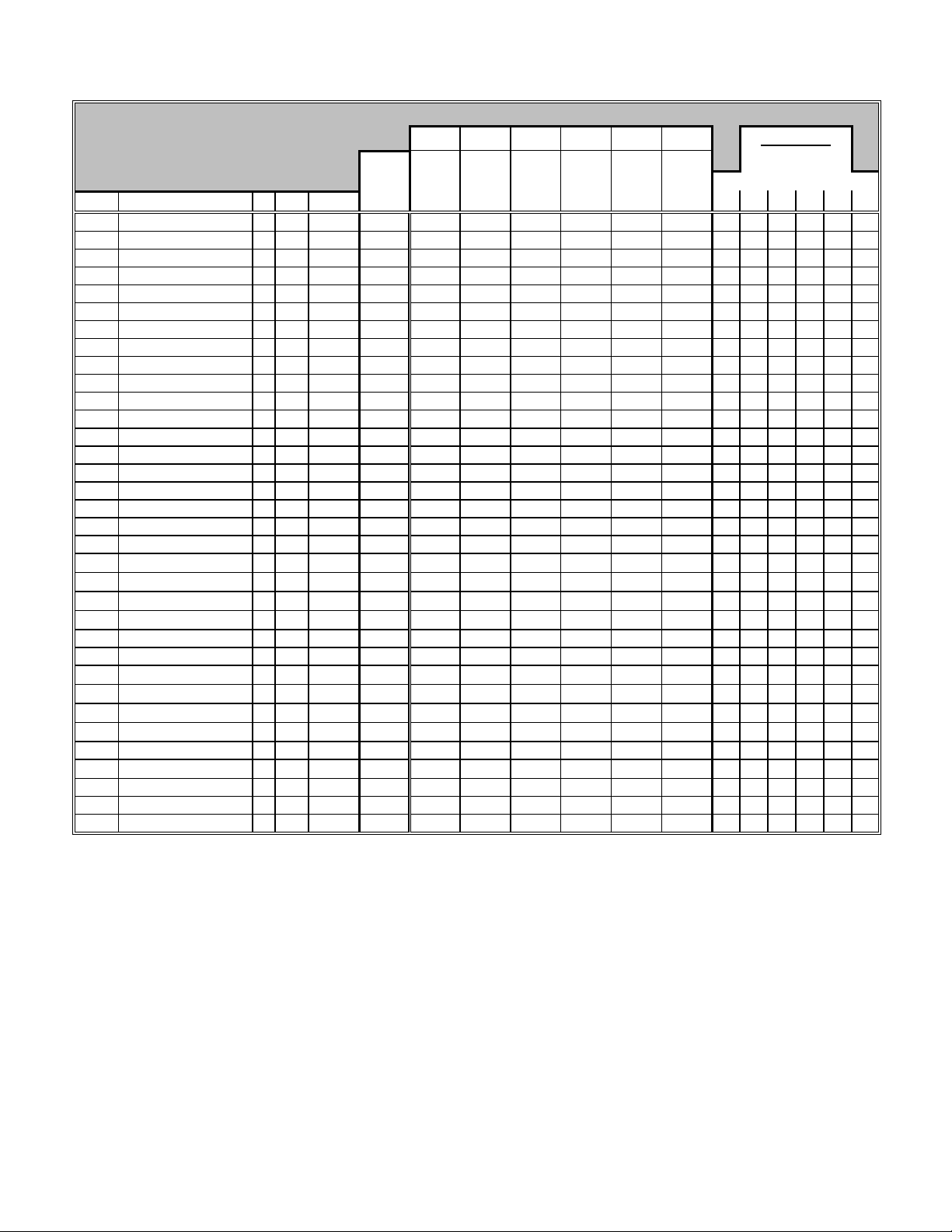
FRE-2 060E
MINIMUM BOARD REQUIREMENTS
READ ACROSS for minimum board revision
Minimum 75150 75151 74027-16
Support 75153 74027-32
Order#
5430
5431
5450
5500
5505
5505
5505
5530
5530
5530
5531
5532
5705
5705
5710
5720
5720
5740
5740
5930
5940
5942
5943
5944
5945
5946
5947
5948
5949
5950
50021
50038
51001
51002
Description
DSDE 4 (10)
ESAF w/ 0 CAMS
Quad ENET
Ace 12
ESA 2x0 (7)
ENET 3 w/Filters
ENET 3F w/Fltrs
DSDE 2 w/Filters (10)
DSDE 2F - Filters (10)
ESA 2x2 (7) (10)
ESAF w/ 2 CAMS
ESAF w/ 6 CAMS
TS416 1x0
TOK - 4/16
Dual Token
TS416 1x1
SST 4/16
TS416 1x2
DST 4/16
Mulitmode FDDI
FDDI Single p-AB
FDDI Single p-A
FDDI Single p-B
MCT1 Single Port
MCT1 Dual Port
Multi FDDI w/CAM
FDDI Sgl p-AB w/CAM
FDDI Sgl p-A w/CAM
FDDI Sgl p-B w/CAM
Quad ENET w/CAM
Quad Token Ring
100 Base-T Enet Link
ATM OC3 MM Link
ATM OC3 SM Link
CR
*
*
*
*
*
*
*
*
*
*
*
*
*
*
*
*
112
232
162
132
132
132
156
156
156
236
236
176
192
194
195
193
169
168
196
198
199
197
164
256
4864
4098
4099
OPTIONS KEY: 1 = Year 2000 Compliance, 2 = Dial-up Services, 3 = Hot swap, 4 = 4MB Series 2 Flash Memory Card Support,
5 = BayStream Support, 6 = Programmable Memory Support.
NOTES:
N/S = Not Supported. Blank = Not Applicable. * = Current release.
(1) = Not supported in software V8.0 and higher.
(2) = Minimum software V7.80 required - Revisions 19 and 20 are NOT supported with the FRE2 processor.
(3) = Minimum software V7.80 required - Revision 8 is NOT supported with the FRE2 processor.
(4) = Minimum software V7.80 required - Revision 12 is NOT supported with the FRE2 processor.
(5) = Revision 25 is recommended if used with FRE-2 processor equipped with 32MB of DRAM.
(6) = Revision 25 is recommended if used with FRE-2 060 processor equipped with 32MB of DRAM or higher.
(7) = Revision 26 is recommended if upgrading from ACE020 to ACE030 processors or if software upgrade is being planned.
(8) = BayStream software only.
(9) = Minimum software V8.01 required.
(10) = VME based products are not supported in software V12.10 and higher.
Part # Revision
ID
102279
106741
102690
100001
2
102495
101597
101976
101256
101938
102494
106738
105970
102484
45
101984
45
103366
102483
44
101980
44
102482
40
101531
40
102675
110458
103755
111462
103753
111459
103754
111460
105201
105207
102675
110458
103755
111462
103753
111459
103754
111460
102690
108034
110848
109874
109914
109913
FRE FRE-2 FRE-2 060
AG0011021
AG0011022
AG0011023
75157
N/S N/S N/S N/S 3 3 3 11 12
3
1
8
1 1 1 1 N/S N/S 1 1 1 1
8 8 8 N/S 8 8 8 14 8
AG0011003 AG0011026
AG0011025
AG0011027
13 - - - -
1
1
3
1
3
3
1
1
1
4
0
1
4
1
4
4
4
4
4
2
2
4
4
4
4
8
1
1
6
6
1 1 (2) N/S N/S 1 10 1 17
1 1 (3) N/S N/S 1 5 1 7
3 3 (4) N/S N/S 3 8 3 11
N/S N/S N/S N/S 1 8 8 11 10
N/S N/S N/S N/S 3 7 7 10 9
N/S N/S N/S N/S 3 12 12 21 20
1 1 1 1 N/S N/S 1 1 1
1 1 1 1 N/S N/S 1 1 1
1 N/S N/S N/S 1 1 1 13
4 N/S N/S N/S 4 4 1 9
0 0 0 N/S 0 0 0 10 0
1 N/S N/S N/S 1 1 1 17 18
4 N/S N/S N/S 4 4 4 10 9
1 1 1 N/S 1 1 1 16 17 1
4 4 4 N/S 4 4 4 10 9 4
12 12 (5) 12 (6) N/S N/S 4 4 19 12
9 9 (5) 9 (6) N/S N/S 4 4 16 9
9 9 (5) 9 (6) N/S N/S 4 4 17
9 9 (5) 9 (6) N/S N/S 4 4 17
2 (8) 2 6 6 N/S 2 (9) 2 2 2
2 (8) 2 6 6 N/S 2 (9) 2 2 2
12 12 (5) 12 (6) N/S N/S 4 4 19 12
9 9 (5) 9 (6) N/S N/S 4 4 16
9 9 (5) 9 (6) N/S N/S 4 4 17
9 9 (5) 9 (6) N/S N/S 4 4 17
8 8 8 N/S 8 8 8 14 8
1 1 1 N/S N/S 1 1 1 1
N/S 1 1 N/S N/S N/S 1 1 1
N/S 6 6 N/S N/S N/S 6 6 6
N/S 6 6 N/S N/S N/S 6 6 6
ACE 020
ACE 030
(1)
5110 5120
5118 5121
5124
13 13 N/S
(10)
OPTIONS
1 2 3 4 5 6
Page 7
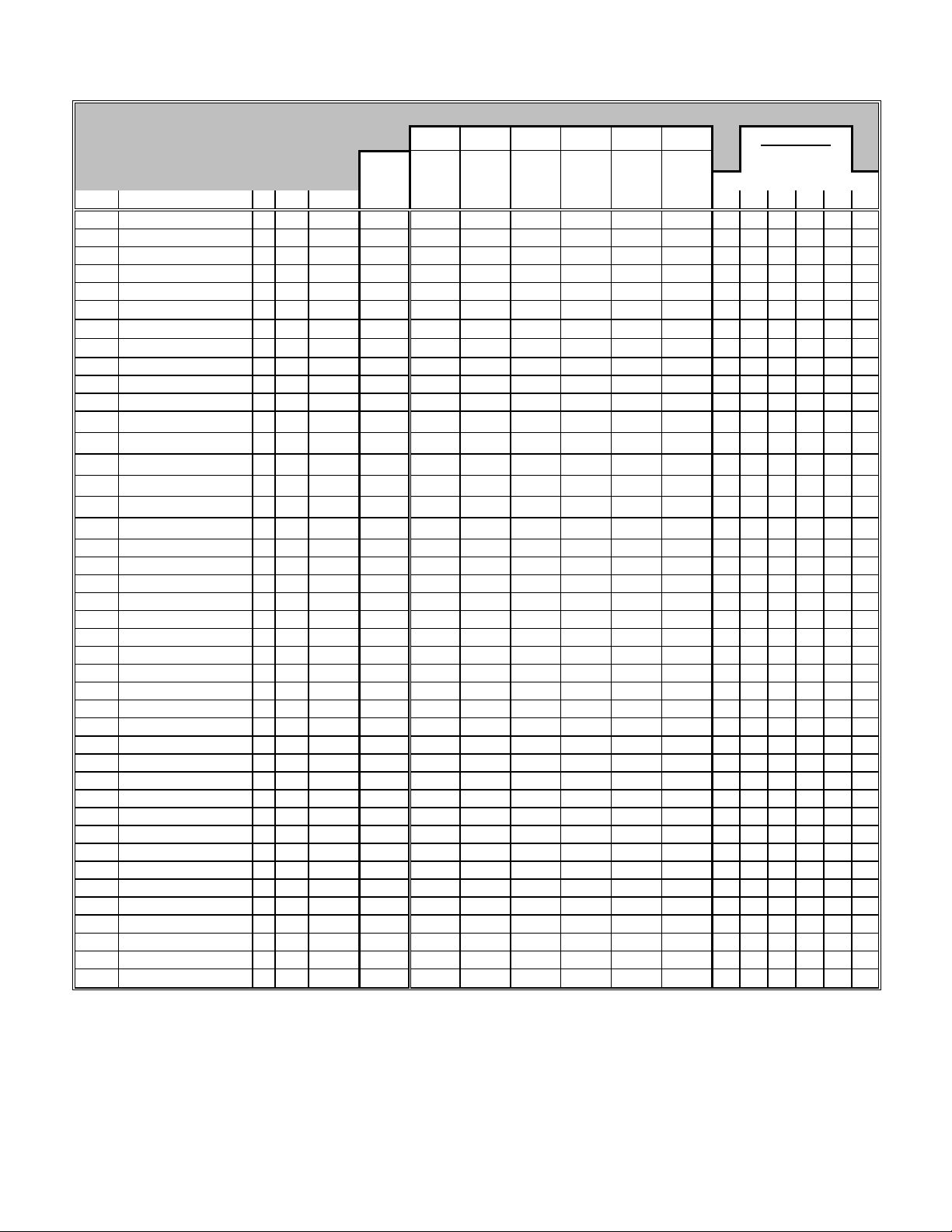
FRE-2 060E
TX FRE4 LINK
DB15/V.54
MINIMUM BOARD REQUIREMENTS
READ ACROSS for minimum board revision
Minimum 75150 75151 74027-16
Support 75153 74027-32
Order#
74027-16
74027-32
75000
75010
75150
75151
75153
75157
77007
77009
AG0011003
AG0011021
AG0011022
AG0011023
AG0011025
AG0011026
AG0011027
AG0011038
AG0011039
AG0011040
AG0011041
AG0011041
AG0011042
AG0011042
AG0011043
AG0011044
AG1304014
AG1311009
AG1311010
AG1311011
AG1311012
AG1311013
AG1311014
AG1311015
AG2104037
AG2104038
AG2104052
AG2111001
AG2111002
AG2111003
AG2111004
AG2111007
OPTIONS KEY: 1 = Year 2000 Compliance, 2 = Dial-up Services, 3 = Hot swap, 4 = 4MB Series 2 Flash Memory Card Support,
Description
FRE-2 060 16MEG
FRE-2 060 32MEG
SRM-L
SRM-F
FRE
FRE-2 8MEG
FRE-2 16MEG
FRE-2 32MEG
MCE1 DUAL PORT
MCE1 SINGLE PORT
FRE-2 060 64MEG
FRE2-060E 16M w/ACC 128 CTXT
FRE2-060E 32M w/ACC 128 CTXT
FRE2-060E 64M w/ACC 128 CTXT
FRE2-060E 16M w/ACC 256 CTXT
FRE2-060E 32M w/ACC 256 CTXT
FRE2-060E 64M w/ACC 256 CTXT
FRE4-PPC 32MB
FRE4-PPC 64MB
FRE4-PPC 128MB
1000BASE-SX FRE4 LINK
1000BASE-SX FRE4 LINK
1000BASE-LX FRE4 LINK
1000BASE-LX FRE4 LINK
4-PORT 10/100BASE4-PORT 100BASE-FX FRE4 LINK
ARE 64MB/6MB BGP SOLOIST
ARE - 8MB DRAM/1MB VBM
ARE -16MB DRAM/3MB VBM
ARE -32MB DRAM/6MB VBM
STS-3/STM-1 MMF ARE Link
STS-3/STM-1 SMF ARE Link
E3 ARE Link Module
DS-3 ARE Link Module
OCTAL SYNC w/ 32CTXT COMP
OCTAL SYNC w/ 128CTXT COMP
QMCT1 LINK MODULE - DS0A
MCE1-II DUAL 120 OHM
MCE1-II SINGLE 120 OHM
MCE1-II DUAL 75 OHM
MCE1-II SINGLE 75 OHM
QMCT1 LINK MOD. -
CR
*
*
*
*
*
*
*
*
*
*
*
*
*
*
*
*
*
*
*
*
*
*
*
*
*
*
*
*
*
*
*
*
*
*
*
*
*
*
*
769
769
8448
8704
256
768
768
768
184
185
769
5633 /
5889
5633 /
5889
5633 /
5889
5633 /
5891
5633 /
5891
5633 /
5891
6656
6656
6656
6400
6400
6401
6401
6144
6145
1280
1280
1280
1280
4608
4609
5121
5120
4353
4354
5378
190
191
188
189
5377
5 = BayStream Support, 6 = Programmable Memory Support.
NOTES:
N/S = Not Supported, Blank = Not Applicable, * = Current release,
(1) = Not supported in software V8.0 and higher.
(2) = Revision 29 or higher is required in order to support AMD “D Series” PCMCIA cards, which require a high true reset, signal input.
(3) = VME based products are not supported in software V12.10 and higher.
Part # Revision
ID
109372-16
109372-32
104270
104276
104100
106450-08
111316-08
106450-16
111316-16
106450-32
111316-32
108199
108687
109372-64
119296-A
119297-A
119298-A
119300-A
119301-A
119302-A
301332-A
301333-A
301334-A
300742-A
300742-B
300757-A
300757-B
300711-A
300727-A
114368-64
110178-08
110178-16
110178-32
110304
110303
109620
109625
112309
112310
114783-A
111607
111609
111022
111378
112001
112001-B
FRE FRE-2 FRE-2 060
AG0011021
AG0011022
AG0011023
75157
2
2
1
1
13
8
8
8
1
1
2
2
2
2
2
2
2
2
2
2
2
3
2
3
2
1
2
1
1
1
1
1
1
1
3
3
1
3
3
3
3
1
2 2 2 2 - - 2 2 2 2 2
2 2 2 2 - - 2 2 2 2 2
1 1 1 1 - - 1 1 1
1 1 1 1 - - 1 1 1
13 13 13 13 - - 13 13 13(2) 13
8 8 8 8 - - 8 8 7 8 8
8 8 8 8 - - 8 8 7 8 8
8 8 8 8 - - 8 8 7 8 8
1 1 1 1 N/S 1 1 1 1
1 1 1 1 N/S 1 1 1 1
2 2 2 2 - - 2 2 2 2 2
2 2 2 2 - - 2 2 2 2
2 2 2 2 - - 2 2 2 2
2 2 2 2 - - 2 2 2 2
2 2 2 2 - - 2 2 2 2
2 2 2 2 - - 2 2 2 2
2 2 2 2 - - 2 2 2 2
2 2 2 2 - - 2 2 2 2
2 2 2 2 - - 2 2 2 2
2 2 2 2 - - 2 2 2 2
N/S N/S N/S N/S - - 2 2 2
N/S N/S N/S N/S - - 3 3 3
N/S N/S N/S N/S - - 2 2 2
N/S N/S N/S N/S - - 3 3 3
N/S N/S N/S N/S - - 2 2 2
N/S N/S N/S N/S - - 1 1 1
2 2 2 2 - - 2 2 2 2 2
1 1 1 1 - - 1 1 1 1 1
1 1 1 1 - - 1 1 1 1 1
1 1 1 1 - - 1 1 1 1 1
N/S N/S N/S N/S - - 1 1 1
N/S N/S N/S N/S - - 1 1 1
N/S N/S N/S N/S - - 1 1 1
N/S N/S N/S N/S - - 1 1 1
3 3 3 N/S N/S N/S 3 3 3 3
3 3 3 N/S N/S N/S 3 3 3 3
N/S 1 1 Y N/S N/S 1 1 1
3 3 3 Y N/S 3 3 3 3
3 3 3 Y N/S 3 3 3 3
3 3 3 Y N/S 3 3 3 3
3 3 3 Y N/S 3 3 3 3
N/S 1 1 Y N/S N/S 1 1 1
AG0011003 AG0011026
AG0011025
AG0011027
ACE 020
ACE 030
(1)
5110 5120
5118 5121
(3)
5124
OPTIONS
1 2 3 4 5 6
Page 8

16
32
BayStream
MINIMUM PROCESSOR AND SOFTWARE REQUIREMENTS
READ ACROSS for MINIMUM SOFTWARE REVISION
READ DOWN for MINIMUM PROCESSOR REVISION
Description:
Order#
5000
5003
5008
5010
5010
5100
5118
5118
5120
5120
5121
5121
5124
5124
5200
5200
5201
5210
5220
5221
5250
5280
5280
5280
5295
5300
5405
5410
5410
5410
5410
5420
5420
5420
5420
5430
5430
75153
75157
Description ID Part #
Syscon
Syscon II
Octal Sync
Sys I/O
Sys I/O
Enet 1
ACE 020
ACE 020
ACE 030
ACE 030
ACE 030 - 8 MEG
ACE 030 - 8 MEG
ACE 030 - 16 MEG
ACE 030 - 16 MEG
T1 II Dual
Dual T1
T1 II 56K
CSU
T1 II Single Port
T1 56K single
E1 75 Ohm
Qsync II
Qsync X
Qsync 4
HSSI
Qsync1
ENET II
SSE
SSE X
SSE 4
SSE2
DSE 2
DSE X
DSE 4
DSE3
DSDE
DSDE X
Model Number:
Part Number:
100007
1
106523
7
109871
4352
100013
48
102937
49
100003
1
101195
3
102330
3
101913
4
103874
4
106727
4
107030
4
107350
4
107352
4
100831
56
100009
24
101667
57
100005
-
101338
58
103496
60
101337
61
100869
80
101924
80
102285
80
104932
225
100011
16
100809
8
101053
32
102213
118
102296
118
101949
118
100860
32
102210
116
102293
116
101945
116
100929
112
101867
112
FRE FRE-2
75150 75151
107350 101913 103874 101163 102329
N/S N/S N/S N/S
N/S N/S N/S N/S
13 8 2 2
N/S N/S N/S N/S
N/S N/S N/S N/S
N/S N/S N/S N/S
N/S N/S N/S N/S
N/S N/S N/S N/S
N/S N/S N/S N/S
N/S N/S N/S N/S
N/S N/S N/S N/S
N/S N/S N/S N/S
N/S N/S N/S N/S
N/S N/S N/S N/S
13 8
N/S N/S N/S N/S N/S N/S N/S
13 8
13 8
13
13
13 8
15 8 2 2 43 33 36 19 23
15 8 2 2 43 33 36 19 23
15 8 2 2 43 33 36 19 23
13 8 2
N/S N/S N/S N/S
13
N/S N/S N/S N/S
13 8 2
13 8 2
13 8 2
N/S N/S N/S N/S
N/S N/S N/S N/S
N/S N/S N/S N/S
N/S N/S N/S N/S
N/S N/S N/S N/S
N/S N/S N/S N/S
NOTES:
(1) = Not supported in software V8.0 and higher.
(2) = Earlier versions of 5 Series software will operate but will only utilize 4MB of memory.
(3) = Will only utilize 8MB of memory. Earlier versions of 5 Series software will operate but will only utilize 4MB of memory.
(4) = Earlier versions of 7 Series software will operate but will only utilize 8MB of memory.
(5) = Minimum software V7.80 required.
(6) = Not supported in software V8.1 and higher.
(7) = VME based products are not supported in software V12.10 and higher.
(8) = Year 2000 compliance is formally supported in BayStream Software V7.1 Rev4.
FRE-2 060
74027-
74027-
N/S N/S N/S
N/S N/S N/S
N/S N/S N/S
FRE-2 060E
AG0011021
AG0011022
AG0011023
AG0011025
AG0011026
AG0011003
AG0011027
N/S N/S
N/S N/S
N/S N/S
N/S N/S
ACE030 ACE030 ACE030 ACE020 ACE020
5124 5120 5120 5110 5110
5124 5121 5121 5118 5118
107352 107030 106727 101195 102330
(4) (4) (4) (1) (1)
5
43 33 36 19 23
43 33 36 19 23
N/S N/S N/S N/S N/S
43 33 36 19 23
43 33 36 19 23
43 33 36 19 23
43 33 36 19 23
43 33 36 19 23
43 33 36 19 23
43 33 36 19 23
43 33 36 19 23
43 33 36 19 23
43 33 36 19 23
43 33 36 19 23
43 33 36 19 23
19 23
43 33 36 19 23
43 33 36 19 23
43 33 36 19 23
43 33 36 19 23
43 33 36 19 23
43 (5) 33 (5) 36 (5)
N/S
N/S N/S
43 33 36 19 23
43 33 36 19 23
43 33 36 19 23
N/S
N/S
N/S
43 33 36 19 23
43 33 36 19 23
43 33 36 19 23
43 33 36 19 23
43 33 36 19 23
43 33 36 19 23
43 33 36 19 23
43 33 36 19 23
43 33 36 19 23
S/W S/W
Version Version
7 & UP
5.70 7.60 (6) N/S
5.77 7.60 (7) N/S
N/S 9.00 5.00
5.70 7.60 (7) N/S
5.70 7.60 (7) N/S
5.70 N/S N/S
5.70 7.60 (1) N/S
5.70 7.60 (1) N/S
5.70 7.60 (7) N/S
5.70 7.60 (7) N/S
5.78 (2) 7.60 (7) N/S
5.78 (2) 7.60 (7) N/S
5.78 (3) 7.70(4) (7) N/S
5.78 (3) 7.70(4) (7) N/S
5.70 7.50 N/S
5.70 N/S N/S
5.70 7.50 N/S
5.70 7.50 N/S
5.70 7.50 N/S
5.70 7.50 N/S
5.70 7.50 N/S
5.70 7.50 3.20
5.70 7.50 3.20
5.70 7.50 3.20
N/S 7.50 3.20
5.70 N/S N/S
5.70 7.50 N/S
5.70 N/S N/S
5.70 7.50 3.20
5.70 7.50 3.20
5.70 7.50 3.20
5.70 N/S N/S
5.70 7.60 (7) N/S
5.70 7.60 (7) N/S
5.70 7.60 (7) N/S
5.70 7.60 (7) N/S
5.70 7.60 (7) N/S
S/W
(8)
Page 9

MINIMUM PROCESSOR AND SOFTWARE REQUIREMENTS
16
32
READ ACROSS for MINIMUM SOFTWARE REVISION
READ DOWN for MINIMUM PROCESSOR REVISION
Description:
Order#
5430
5431
5450
5500
5505
5505
5505
5530
5530
5530
5531
5532
5705
5705
5710
5720
5720
5740
5740
5930
5940
5942
5943
5944
5945
5946
5947
5948
5949
5950
50021
50038
51001
51002
74027-16 FRE-2 060 16MEG
74027-32 FRE-2 060 32MEG
NOTES:
(1) = Not supported in software V8.0 and higher.
(2) = Minimum software V7.80 required.
(3) = BNX software only.
(4) = Minimum software V8.01 required.
(5) = Boards with serial number 003920 and above require minimum BayStream (BNX) software V4.11 or V4.21.
(6) = VME based products are not supported in software V12.10 and higher.
(7) = Year 2000 compliance is formally supported in BayStream Software V7.1 Rev4.
(8) = Minimum software V8.11 / fix 1 required.
75153
75157
Description ID Part #
DSDE 4
ESAF w/ 0 CAMS
Quad ENET
Ace 12
ESA 2x0
ENET 3 w/Filters
ENET 3F w/Filters
DSDE 2 w/Filters
DSDE 2F - Filters
ESA 2x2
ESAF w/ 2 CAMS
ESAF w/ 6 CAMS
TS416 1x0
TOK - 4/16
Dual Token
TS416 1x1
SST 4/16
TS416 1x2
DST 4/16
Mulitmode FDDI
FDDI Single p-AB
FDDI Single p-A
FDDI Single p-B
MCT1 Single Port
MCT1 Dual Port
Multi FDDI w/CAM
FDDI Sgl p-AB w/CAM
FDDI Sgl p-A w/CAM
FDDI Sgl p-B w/CAM
Quad ENET w/CAM
Quad Token Ring
100 Base-T Enet Link
ATM OC3 MM Link
ATM OC3 SM Link
Model Number:
Part Number:
102279
112
106741
232
102690
162
100001
-
102495
132
101597
132
101976
132
101256
156
101938
156
102494
156
106738
236
105970
236
102484
45
101984
45
103366
176
102483
44
101980
44
102482
40
101531
40
102675
192
110458
103755
194
111462
103753
195
111459
103754
193
111460
105201
169
105207
168
102675
196
110458
103755
198
111462
103753
199
111459
103754
197
111460
102690
164
108034
256
110848
109874
4864
109914
4098
109913
4099
109372-16
769
109372-32
769
FRE FRE-2
75150 75151
107350 101913 103874 101163 102329
N/S N/S N/S N/S
13 8 2 2
13 8 2
N/S N/S N/S N/S
13 8 (2)
13 8 (2)
13 8 (2)
N/S N/S N/S N/S
N/S N/S N/S N/S
N/S N/S N/S N/S
13 8 2 2
13 8 2 2
13
13
13 8 2
13
13
13 8 2
13 8 2
15 8 2
15 8 2
15 8 2
15 8 2
13 (3) 8 2 2 43 (4) 33 (4) 36 (4)
13 (3) 8 2 2 43 (4) 33 (4) 36 (4)
15 8 2
15 8 2
15 8 2
15 8 2
13 8 2
13 8 2
N/S
N/S
N/S
13 8 2 2
13 8 2 2
FRE-2 060
74027-
74027-
N/S N/S N/S
N/S N/S N/S
N/S N/S N/S
N/S N/S N/S
8 2
8 2
8 2
FRE-2 060E
AG0011021
AG0011022
AG0011023
AG0011025
AG0011026
AG0011003
AG0011027
N/S N/S
N/S N/S
N/S N/S
ACE030 ACE030 ACE030 ACE020 ACE020
5124 5120 5120 5110 5110
5124 5121 5121 5118 5118
107352 107030 106727 101195 102330
(4) (4) (4) (1) (1)
5
43 33 36 19 23
N/S N/S N/S N/S N/S
N/S
43 33 36 26 25
43 33 36 19 23
43 33 36 19 23
43 33 36 19 23
43 33 36 19 23
43 33 36 19 23
43 33 36 19 23
43 33 36 19 23
N/S N/S N/S N/S N/S
N/S N/S N/S N/S N/S
43 33 36 19 23
43 33 36 19 23
N/S
43 33 36 25 24
43 33 36 19 23
43 33 36 19 23
N/S
N/S
N/S
N/S
N/S
N/S
N/S
N/S
N/S
N/S
N/S
N/S
43 33 36 19 23
43 33 36 19 23
43 33 36
43 33 36
43 33 36
43 33 36
43 33 36
43 33 36
43 33 36
43 33 36
43 33 36
43 41 41
N/S N/S N/S N/S N/S N/S
N/S N/S N/S N/S N/S N/S
N/S N/S N/S N/S N/S N/S
N/S N/S N/S N/S N/S
N/S N/S N/S N/S N/S
N/S N/S
N/S N/S
N/S N/S
N/S N/S
N/S N/S
N/S N/S
N/S N/S
N/S N/S
N/S N/S
N/S N/S
N/S N/S
N/S N/S
S/W S/W
Version Version
5.70 7.60 (6) N/S
N/S 7.70 4.20
5.70 7.50 3.20
5.70 N/S N/S
5.70 7.50 N/S
5.70 7.50 N/S
5.70 7.50 N/S
5.70 7.60 (6) N/S
5.70 7.60 (6) N/S
5.70 7.60 (6) N/S
N/S 7.70 N/S
N/S 7.70 N/S
5.70 7.50 N/S
5.70 7.50 N/S
5.72 7.50 4.20
5.70 7.50 N/S
5.70 7.50 N/S
5.70 7.50 4.20
5.70 7.50 4.20
5.70 7.50 3.20
5.70 7.50 3.20
5.70 7.50 N/S
5.70 7.50 N/S
N/S 7.80 6.00
N/S 7.80 3.20 (5)
5.70 7.55 3.20
5.70 7.55 N/S
5.70 7.55 N/S
5.70 7.55 N/S
5.70 7.50 3.20
N/S 8.11 6.00
N/S 9.00 5.00
N/S 8.11 / 1 (8) 5.00
N/S 8.11 / 1 (8) 5.00
N/S 8.10 5.00
N/S 8.10 5.00
BayStream
S/W
7 & UP
(7)
Page 10

MINIMUM PROCESSOR AND SOFTWARE REQUIREMENTS
16
32
TX FRE4 LINK
DB15/V.54
READ ACROSS for MINIMUM SOFTWARE REVISION
READ DOWN for MINIMUM PROCESSOR REVISION
Description:
Order#
75000
75010
75150
75151
75153
75157
77007
77009
AG0011003
AG0011021
AG0011022
AG0011023
AG0011025
AG0011026
AG0011027
AG0011038
AG0011039
AG0011040
AG0011041
AG0011042
AG0011043
AG0011044
AG1304014
AG1311009
AG1311010
AG1311011
AG1311012
AG1311013
AG1311014
AG1311015
AG2104037
AG2104038
AG2104052
AG2111001
AG2111002
AG2111003
AG2111004
AG2111007
NOTES:
(1) = Not supported in software V8.0 and higher.
(2) = V4.10 Diagnostic code required.
(3) = VME based products are not supported in software V12.10 and higher.
(4) = Year 2000 compliance is formally supported in BayStream Software V7.1 Rev4.
(5) == FRE is not supported in software V12.10 and higher.
75153
75157
Description ID Part #
SRM-L
SRM-F
FRE
FRE-2 8MEG
FRE-2 16MEG
FRE-2 32MEG
MCE1 DUAL PORT
MCE1 SINGLE PORT
FRE-2 060 64MEG
FRE2-060E 16M w/ACC 128 CTXT
FRE2-060E 32M w/ACC 128 CTXT
FRE2-060E 64M w/ACC 128 CTXT
FRE2-060E 16M w/ACC 256 CTXT
FRE2-060E 32M w/ACC 256 CTXT
FRE2-060E 64M w/ACC 256 CTXT
FRE4-PPC 32MB
FRE4-PPC 64MB
FRE4-PPC 128MB
1000BASE-SX FRE4 LINK
1000BASE-LX FRE4 LINK
4-PORT 10/100BASE4-PORT 100BASE-FX FRE4 LINK
ARE 64MB/6MB BGP SOLOIST
ARE -8MB DRAM/1MB VBM
ARE-16MB DRAM/3MB VBM
ARE-32MB DRAM/6MB VBM
STS-3/STM-1 MMF ARE Link
STS-3/STM-1 SMF ARE Link
E3 ARE Link Module
DS-3 ARE Link Module
OCTAL SYNC w/ 32CTXT COMP
OCTAL SYNC w/ 128CTXT COMP
QMCT1 LINK MODULE - DS0A
MCE1-II DUAL 120 OHM
MCE1-II SINGLE 120 OHM
MCE1-II DUAL 75 OHM
MCE1-II SINGLE 75 OHM
QMCT1 LINK MOD. -
Model Number:
Part Number:
104270
8448
104276
8704
104100
256
106450-08
768
111316-08
106450-16
768
111316-16
106450-32
768
111316-32
108199
184
108687
185
109372-64
769
5633 /
119296-A
5889
5633 /
119297-A
5889
5633 /
119298-A
5889
5633 /
119300-A
5891
5633 /
119301-A
5891
5633 /
119302-A
5891
301332-A
6656
301333-A
6656
301334-A
6656
300742-A
6400
300757-A
6401
300711-A
6144
300727-A
6145
114368-64
1280
110178-08
1280
110178-16
1280
110178-32
1280
110304
4608
110303
4609
109620
5121
109625
5120
112309
4353
112310
4354
114783-A
5378
111607
190
111609
191
111022
188
111378
189
112001
5377
112001-B
FRE FRE-2
75150 75151
107350 101913 103874 101163 102329
13 8 2 2
13 8 2 2
13 8 2 2
13 8 2 2
13 8 2 2
13 8 2 2
13 8 2 2 43 33 36
13 8 2 2 43 33 36
13 8 2 2
13 8 2 2
13 8 2 2
13 8 2 2
13 8 2 2
13 8 2 2
13 8 2 2
13 8 2 2
13 8 2 2
13 8 2 2
N/S N/S N/S N/S N/S N/S N/S N/S N/S
N/S N/S N/S N/S N/S N/S N/S N/S N/S
N/S N/S N/S N/S N/S N/S N/S N/S N/S
N/S N/S N/S N/S N/S N/S N/S N/S N/S
13 8 2 2
13 8 2 2
13 8 2 2
13 8 2 2
N/S N/S N/S N/S N/S N/S N/S N/S N/S
N/S N/S N/S N/S N/S N/S N/S N/S N/S
N/S N/S N/S N/S N/S N/S N/S N/S N/S
N/S N/S N/S N/S N/S N/S N/S N/S N/S
13 8 2
13 8 2
N/S
13 8 2 2 43 33 36
13 8 2 2 43 33 36
13 8 2 2 43 33 36
13 8 2 2 43 33 36
N/S
FRE-2 060
74027-
74027-
8 2
8 2 2
AG0011003
FRE-2 060E
ACE030 ACE030 ACE030 ACE020 ACE020
AG0011021
AG0011022
AG0011023
AG0011025
AG0011026
AG0011027
5124 5120 5120 5110 5110
5124 5121 5121 5118 5118
107352 107030 106727 101195 102330
(3) (3) (3) (1) (1)
5
N/S N/S N/S N/S N/S
N/S N/S N/S N/S N/S
N/S N/S N/S N/S N/S
N/S N/S N/S N/S N/S
N/S N/S N/S N/S N/S
N/S N/S N/S N/S N/S
N/S N/S
N/S N/S
N/S N/S N/S N/S N/S
N/S N/S N/S N/S N/S
N/S N/S N/S N/S N/S
N/S N/S N/S N/S N/S
N/S N/S N/S N/S N/S
N/S N/S N/S N/S N/S
N/S N/S N/S N/S N/S
N/S N/S N/S N/S N/S
N/S N/S N/S N/S N/S
N/S N/S N/S N/S N/S
N/S N/S N/S N/S N/S
N/S N/S N/S N/S N/S
N/S N/S N/S N/S N/S
N/S N/S N/S N/S N/S
N/S N/S N/S N/S N/S N/S
N/S N/S N/S N/S N/S N/S
N/S N/S N/S N/S N/S N/S
N/S N/S
N/S N/S
N/S N/S
N/S N/S
N/S N/S N/S N/S N/S
S/W S/W
Version Version
N/S 7.00 3.20
N/S 7.00 3.20
N/S 7.00(5) 3.20
N/S 7.70 4.10
N/S 7.70 4.10
N/S 7.70 4.10
N/S 8.10 4.20
N/S 8.10 6.00
N/S 10.00 (2) 6.00
N/S 12.20 N/S
N/S 12.20 N/S
N/S 12.20 N/S
N/S 12.20 N/S
N/S 12.20 N/S
N/S 12.20 N/S
N/S 13.20 7.40
N/S 13.20 7.40
N/S 13.20 7.40
N/S 13.20 7.40
N/S 13.20 7.40
N/S 13.20 7.40
N/S 13.20 7.40
N/S 9.01 6.00
N/S 9.01 6.00
N/S 9.01 6.00
N/S 9.01 6.00
N/S 9.01 6.00
N/S 9.01 6.00
N/S 10.00 6.10
N/S 10.00 6.10
N/S 10.00 6.00
N/S 10.00 6.00
N/S 11.02 7.0 Rev.3
N/S 9.00 6.00
N/S 9.00 6.00
N/S 9.00 6.00
N/S 9.00 6.00
N/S 11.00 6.00
BayStream
7 & UP
S/W
(4)
Page 11
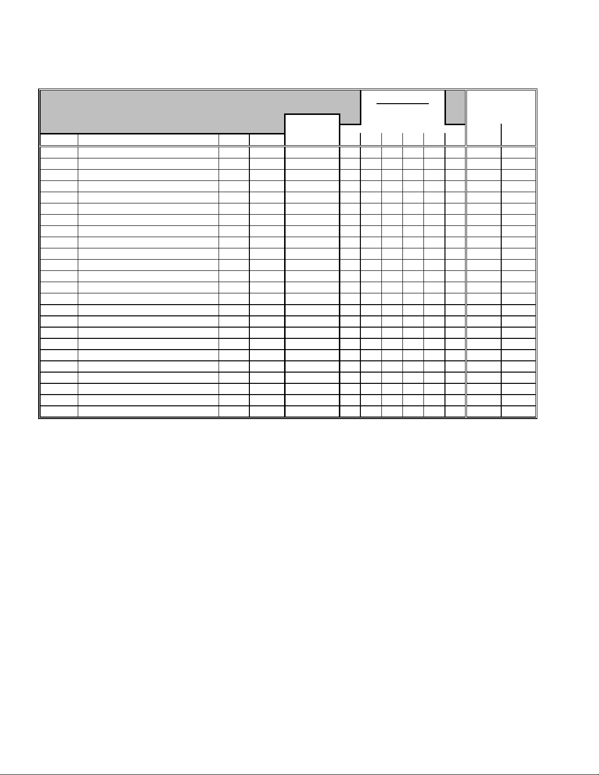
ACCESS FEEDER NODES
READ ACROSS for minimum requirements *
Order#
1515
1516
1517
1518
1520
1521
1525
1526
1527
1528
1529
1530
15000
15001
15002
15003
15004
15005
15006
15007
15008
15009
15010
15011
OPTIONS KEY: 1 = Year 2000 Compliance, 2 = Dial-up Services, 3 = Madge1, 4 = Madge2 Fastmac+,
AFNES V.35 (4)
AFNES X.21 (4)
AFNES CCITT V.35 (4)
AFNES RS422 (4)
AFNTS 1x2 (4)
AFNTS 2x2 (4)
AFNES V.35 w/Flash
AFNES X.21 w/Flash
AFNES CCITT V.35 w/Flash
AFNES RS422 w/Flash
AFNTS 1x2 w/Flash
AFNTS 2x2 w/Flash
AFNES 16M V.35 (4)
AFNES 16M X.21 (4)
AFNES 16M CCITT V.35 (4)
AFNES 16M RS422 (4)
AFNES 16M V.35 w/Flash
AFNES 16M X.21 w/Flash
AFNES 16M CCITT V.35 w/Flash
AFNES 16M RS422 w/Flash
AFNTS 1x2 16M (4)
AFNTS 2x2 16M (4)
AFNTS 1x2 16M w/Flash
AFNTS 2x2 16M w/Flash
Description ID
208
208
208
208
217
216
208
208
208
208
217
216
208
208
208
208
208
208
208
208
217
216
217
216
Part # Revision 1 2 3 4 5 6
104760
104760
104760
104760
105530
105533
106514
106514
106514
106514
106512
106516
107934
107934
107934
107934
107932
107932
107932
107932
107936
107940
107938
107942
Minimum
Support Version Version
27 N/S
27 N/S
27 N/S
27 N/S
14 N/S
14 N/S
35
35
35
35
19
16
38 N/S
38 N/S
38 N/S
38 N/S
38
38
38
38
25 N/S
25 N/S
25
25
5 = 4MB Series 2 Flash Memory Card Support, 6 = Programmable Memory Support.
NOTES:
* Access Feeder Node products are not supported in software V12.10 and higher.
N/S = Not Supported
Blank = Not Applicable
(1) = Earlier versions of 5 Series software will operate but will only utilize 4MB of memory.
(2) = Minimum revision 45 required to support 4MB Flash Memory Cards manufactured by AMD or AMP. Revision levels
relate to units shipped from the factory. The required code is PROM based and can be field updated.
(3) = Minimum revision 32 required to support 4MB Flash Memory Cards manufactured by AMD or AMP. Revision levels
relate to units shipped from the factory. The required code is PROM based and can be field updated.
(4) = Floppy based units are not supported in software V8.1 and higher.
(5) = Units below revision 46 require a PROM update in order to operate software V8.1 or higher.
(6) = Units below revision 33 require a PROM update in order to operate software V8.1 or higher.
46 (5) 38 41 (2)
46 (5) 38 41 (2)
46 (5) 38 41 (2)
46 (5) 38 41 (2)
33 (6) 22 19 25 29 (3)
33 (6) 19 16 22 26 (3)
46 (5) 38 41 (2) 38
46 (5) 38 41 (2) 38
46 (5) 38 41 (2) 38
46 (5) 38 41 (2) 38
33 (6) 25 25 28 (3) 25
33 (6) 25 25 28 (3) 25
OPTIONS
38
38
38
38
22 14 25
19 14 22
38 38
38 38
38 38
38 38
25 25 25
25 25 25
MINIMUM
SOFTWARE
REQUIRMENTS
(1) 5.78
(1) 5.78
(1) 5.78
(1) 5.78
(1) 5.78
(1) 5.78
7 & UP *
5
5.75 7.56
5.75 7.56
5.75 7.56
5.75 7.56
5.76 7.56
5.76 7.56
N/S
N/S
N/S
N/S
N/S
N/S
N/S
N/S
N/S
N/S
N/S
N/S
7.56
7.56
7.56
7.56
7.56
7.56
7.60
7.60
7.60
7.60
7.60
7.60
7.60
7.60
7.60
7.60
7.60
7.60
Page 12

ACCESS NODES
READ ACROSS for minimum requirements
Order# Description
20001
20002
20003
20004
21002
21003
21004
22002
22003
22004
AN-ENET 1X2 1M FLASH/4M DRAM
AN-ENET 1X2 4MB DRAM
AN-ENET 1X2 8MB DRAM
AN-ENET 1X2 16MB DRAM
AN-ENET 1X2 xxMB DRAM w/ISDN S/T
AN-ENET 1X2 xxMB DRAM w/3 SYNC
AN-ENET 1X2 xxMB DRAM w/2ND ENET
AN-ENET 1X2 xxMB DRAM w/ CSU/DSU
AN-ENET 1X2 xxMB DRAM w/ T1/FT1
AN-ENET 1X2 xxMB DRAM w/ E1/FE1
AN-TOKEN1X2 4MB DRAM
AN-TOKEN 1X2 8MB DRAM
AN-TOKEN 1X2 16MB DRAM
AN-TOKEN 1X2 xxMB DRAM w/ ISDN S/T
AN-TOKEN 1X2 xxMB DRAM w/3 SYNC
AN-TOKEN 1X2 xxMB DRAM w/ CSU/DSU
AN-TOKEN 1X2 xxMB DRAM w/ T1/FT1
AN-TOKEN 1X2 xxMB DRAM w/ E1/FE1
AN-ENET/TOKEN 2X2 4MB DRAM
AN-ENET/TOKEN 2X2 8MB DRAM
AN-ENET/TOKEN 2X2 16MB DRAM
AN-ETS 2X2 xxMB DRAM w/ ISDN S/T
AN-ETS 2X2 xxMB DRAM w/3 SYNC
AN-ETS 2X2 xxMB DRAM w/ CSU/DSU
AN-ETS 2X2 xxMB DRAM w/ T1/FT1
AN-ETS 2X2 xxMB DRAM w/ E1/FE1
CR
ID Part #
1024
1024
1024
1024
1027
1030
1033
1090
1100
1119
1037
1037
1037
1038
1039
1091
1102
1121
1025
1025
1025
1028
1031
1092
1104
1123
106993
106993 / 110313
106993 / 110313
106993 / 110313
107907 / 110312
107907 / 110312
107907 / 110312
108308 / 110313
108308 / 110313
108308 / 110313
OPTIONS KEY:
1 = Year 2000 Compliance - units shipping from the factory. The required code to support V8.10 and higher Router Software is PROM based
and can be field updated.
2 = Dial-up Services.
3 = 4MB Flash Memory SIMM Support - units shipping from the factory. The required code is PROM based and can be field updated.
4 = Programmable Memory Support.
NOTES:
Blank = Not Applicable
* = Current release.
(1) = Diagnostic PROM code V7.24 or higher is required to support the CSU/DSU Adapter Module.
(2) = Diagnostic PROM code V7.30 or higher is required to support the T1/FT1 Adapter Module.
(3) = Diagnostic PROM code V7.32 or higher is required to support the E1/FE1 Adapter Module.
External Model number labeling refers to the base system’s LAN technology and DRAM size configuration only, and does not reflect
the presence of optional add-on cards (ISDN S/T BRI, 3rd SYNC, 2nd ETHERNET, CSU/DSU, T1/FT1, and E1/FE1).
Rows with blank Order# fields contain information specific to units configured with optional add-on cards, independent of DRAM size
configurations. Only those configurations that are listed are supported.
Minimum
Support
Revision 1 2 3 4
3
3
3
3
6
15
15
15
15
15
7
7
7
7
12
14
14
14
7
7
7
7
11
14
14
14
OPTIONS
14 3 7 3
14 3 7 3
14 3 7 3
14 3 7 3
14 6 7 6
15 15 15 15
15 15 15 15
15 15 15 15
15 15 15 15
15 15 15 15
14 7 7 7
14 7 7 7
14 7 7 7
14 7 7 7
14 12 12 12
14 12 12 12
14 12 12 12
14 12 12 12
14 7 7 7
14 7 7 7
14 7 7 7
14 7 7 7
14 11 11 11
14 11 11 11
14 11 11 11
14 11 11 11
MINIMUM
SOFTWARE
REQUIRMENTS
V11.01 (1)
V12.10 (2)
V12.20 (3)
V11.01 (1)
V12.10 (2)
V12.20 (3)
V11.01 (1)
V12.10 (2)
V12.20 (3)
V7.70
V7.70
V7.70
V7.70
V8.10
V8.10
V8.12
V7.80
V7.80
V7.80
V8.10
V8.10
V7.80
V7.80
V7.80
V8.10
V8.10
Page 13
ACCESS NODES (continued)
READ ACROSS for minimum requirements
Order# Description
23002
23003
23004
23102
23103
23104
50022
50025
AE0011010
AE0011025
AE0011029
AE0011031
AE0011032
ANH -12 4MB DRAM
ANH -12 8MB DRAM
ANH -12 16MB DRAM
ANH -12 xxMB DRAM w/ ISDN S/T
ANH -12 xxMB DRAM w/3 SYNC
ANH -12 xxMB DRAM w/2ND ENET
ANH -12 xxMB DRAM w/ CSU/DSU
ANH -12 xxMB DRAM w/ T1/FT1
ANH -12 xxMB DRAM w/ E1/FE1
ANH -8 4MB DRAM (4)
ANH -8 8MB DRAM (4)
ANH -8 16MB DRAM (4)
ISDN S/T ADAPTER MODULE UPGRADE
3RD SYNC ADAPTER MODULE UPGRADE
2ND ENET ADAPTER MODULE UPGRADE
CSU/DSU ADAPTER MODULE UPGRADE
T1/FT1 ADAPTER MODULE UPGRADE
E1/FE1(RJ) ADAPTER MODULE UPGRADE
E1/FE1(BNC) ADAPTER MODULE UPGRADE
CR
ID Part #
1026
1026
1026
1029
1032
1035
1093
1106
1125
1047 980-763-X
1047 980-766-X
1047 980-771-X
- 107977
*
- 108714
*
- 111658
*
- 115112-A
*
- 114922-A
*
- 300319-A
*
- 300319-A
*
108308 / 110313
108308 / 110313
108308 / 110313
OPTIONS KEY:
1 = Year 2000 Compliance - units shipping from the factory. The required code to support V8.10 and higher Router Software is PROM based
and can be field updated.
2 = Dial-up Services.
3 = 4MB Flash Memory SIMM Support - units shipping from the factory. The required code is PROM based and can be field updated.
4 = Programmable Memory Support.
NOTES:
Blank = Not Applicable
* = Current release.
(1) = Diagnostic PROM code V7.24 or higher is required to support the CSU/DSU Adapter Module.
(2) = Diagnostic PROM code V7.30 or higher is required to support the T1/FT1 Adapter Module.
(3) = Diagnostic PROM code V7.32 or higher is required to support the E1/FE1 Adapter Module.
(4) = These ANH-8 units will not support any optional add-on serial cards (ISDN, 3
External Model number labeling refers to the base system’s LAN technology and DRAM size configuration only, and does not reflect
the presence of optional add-on cards (ISDN S/T BRI, 3rd SYNC, 2nd ETHERNET, CSU/DSU, T1/FT1, and E1/FE1).
Rows with blank Order# fields contain information specific to units configured with optional add-on cards, independent of DRAM size
configurations. Only those configurations that are listed are supported.
Minimum
Support
Revision 1 2 3 4
8
8
8
8
11
14
14
14
14
A0
A0
A0
1
1
3
2
1
1
1
rd
SYNC, 2nd ENET, CSU/DSU, T1/FT1, and E1/FE1).
OPTIONS
14 8 8 8
14 8 8 8
14 8 8 8
14 8 8 8
14 11 11 11
14 11 11 11
14 11 11 11
14 11 11 11
14 11 11 11
A0 A0 A0 A0
A0 A0 A0 A0
A0 A0 A0 A0
1
1 1
1
2
1
1
1
MINIMUM
SOFTWARE
REQUIRMENTS
V11.01 (1)
V12.10 (2)
V12.20 (3)
V11.01 (1)
V12.10 (2)
V12.20 (3)
V12.20 (3)
V8.00
V8.00
V8.00
V8.10
V8.10
V8.12
V8.10
V8.10
V8.10
V8.10
V8.10
V8.12
Page 14

BAYSTACK ACCESS NODES
READ ACROSS for minimum requirements
ORDER # DESCRIPTION
AE1001006
AE1001007
AE1001008
AE1001010
AE1001011
AE1001012
AN-ENET 1X2 4MB DRAM
AN-ENET 1X2 8MB DRAM
AN-ENET 1X2 16MB DRAM
AN-ENET 1X2 xxMB DRAM w/ ISDN S/T
AN-ENET 1X2 xxMB DRAM w/ 3RD SYNC
AN-ENET 1X2 xxMB DRAM w/ 2ND ENET
AN-ENET 1X2 xxMB DRAM w/ CSU/DSU
AN-ENET 1X2 xxMB DRAM w/ T1/FT1
AN-ENET 1X2 xxMB DRAM w/ E1/FE1
AN-ENET 1X2 xxMB DRAM w/ N11 DCM
AN-ENET 1X2 xxMB DRAM w/ ISDN S/T & N11 DCM
AN-ENET 1X2 xxMB DRAM w/ 3RD SYNC & N11 DCM
AN-ENET 1X2 xxMB DRAM w/ 2ND ENET & N11 DCM
AN-ENET 1X2 xxMB DRAM w/ CSU/DSU & N11 DCM
AN-ENET 1X2 xxMB DRAM w/ T1/FT1 & N11 DCM
AN-ENET 1X2 xxMB DRAM w/ E1/FE1 & N11 DCM
ANH-8 4MB DRAM
ANH-8 8MB DRAM
ANH-8 16MB DRAM
ANH-8 xxMB DRAM w/ ISDN S/T
ANH-8 xxMB DRAM w/ 3RD SYNC
ANH-8 xxMB DRAM w/ 2ND ENET
ANH-8 xxMB DRAM w/ CSU/DSU
ANH-8 xxMB DRAM w/ T1/FT1
ANH-8 xxMB DRAM w/ E1/FE1
ANH-8 xxMB DRAM w/ N11 DCM
ANH-8 xxMB DRAM w/ ISDN S/T & N11 DCM
ANH-8 xxMB DRAM w/ 3RD SYNC & N11 DCM
ANH-8 xxMB DRAM w/ 2ND ENET & N11 DCM
ANH-8 xxMB DRAM w/ CSU/DSU & N11 DCM
ANH-8 xxMB DRAM w/ T1/FT1 & N11 DCM
ANH-8 xxMB DRAM w/ E1/FE1 & N11 DCM
CR
ID Part #
1024 111375
1024 111375
*
1024 111375
*
1043
*
1030
*
1033
*
1090
*
1100
*
1119
*
1055
*
1062
*
1056
*
1057
*
1095
*
1114
*
1133
*
1047 113359
1047 113359
*
1047 113359
*
1051
*
1049
*
1050
*
1094
*
1108
*
1127
*
1048
*
1054
*
1052
*
1053
*
1099
*
1118
*
1137
*
NOTES:
Dial-up Services and Programmable Memory features are supported by all BayStack Access Node models.
* = Current release.
(1) = All units at the Minimum Support Revision or higher are considered Year 2000 Compliant when operating with Router Software
V11.03 (Site Manager 5.03) or Router Software V12.0 Rev2 (Site Manager 6.0 Rev2) and higher.
(2) = Diagnostic PROM code V7.24 or higher is required to support the CSU/DSU Adapter Module.
(3) = Diagnostic PROM code V7.30 or higher is required to support the T1/FT1 Adapter Module.
(4) = Diagnostic PROM code V7.32 or higher is required to support the E1/FE1 Adapter Module
External Model number labeling refers to the base system’s LAN technology and DRAM size configuration only, and does not reflect
the presence of optional add-on cards (ISDN S/T BRI, 3rd SYNC, 2nd ENET, CSU/DSU, T1/FT1, E1/FE1, & N11 DCM). Rows with
blank ORDER# fields contain information specific to units configured with optional add-on cards, independent of DRAM size
configurations. Only those configurations that are listed are supported.
Minimum
Support SOFTWARE
Revision (1) REQUIRMENTS
1
1
1
1
1
1
1
1
1
1
1
1
1
1
1
1
D0
D0
D0
D0
D0
D0
D0
D0
D0
D0
D0
D0
D0
D0
D0
D0
MINIMUM
V8.12
V8.12
V8.12
V8.12
V8.12
V8.12
V11.01 (2)
V12.10 (3)
V12.20 (4)
V9.00
V9.00
V9.00
V9.00
V11.01 (2)
V12.10 (3)
V12.20 (4)
V8.12
V8.12
V8.12
V8.12
V8.12
V8.12
V11.01 (2)
V12.10 (3)
V12.20 (4)
V9.00
V9.00
V9.00
V9.00
V11.01 (2)
V12.10 (3)
V12.20 (4)
Page 15

BAYSTACK ACCESS NODES (continued)
READ ACROSS for minimum requirements
ORDER # DESCRIPTION
AE1001014
AE1001015
AE1001016
AE1101002
AE1101003
AE1101004
AE1101006
AE1101007
AE1101008
NOTES:
ANH-12 4MB DRAM
ANH-12 8MB DRAM
ANH-12 16MB DRAM
ANH-12 xxMB DRAM w/ ISDN S/T
ANH-12 xxMB DRAM w/ 3RD SYNC
ANH-12 xxMB DRAM w/ 2ND ENET
ANH-12 xxMB DRAM w/ CSU/DSU
ANH-12 xxMB DRAM w/ T1/FT1
ANH-12 xxMB DRAM w/ E1/FE1
AN-TOKEN RING 1X2 4MB DRAM
AN-TOKEN RING 1X2 8MB DRAM
AN-TOKEN RING 1X2 16MB DRAM
AN-TOKEN RING 1X2 xxMB DRAM w/ ISDN S/T
AN-TOKEN RING 1X2 xxMB DRAM w/ 3RD SYNC
AN-TOKEN RING 1X2 xxMB DRAM w/ CSU/DSU
AN-TOKEN RING 1X2 xxMB DRAM w/ T1/FT1
AN-TOKEN RING 1X2 xxMB DRAM w/ E1/FE1
AN-ENET/TOKEN RING 2X2 4MB DRAM
AN-ENET/TOKEN RING 2X2 8MB DRAM
AN-ENET/TOKEN RING 2X2 16MB DRAM
AN-ENET/TOKEN 2X2 xxMB DRAM w/ ISDN S/T
AN-ENET/TOKEN 2X2 xxMB DRAM w/ 3RD SYNC
AN-ENET/TOKEN 2X2 xxMB DRAM w/ CSU/DSU
AN-ENET/TOKEN 2X2 xxMB DRAM w/ T1/FT1
AN-ENET/TOKEN 2X2 xxMB DRAM w/ E1/FE1
AN-ENET/TOKEN 2X2 xxMB DRAM w/ N11 DCM
AN-ENET/TOKEN 2X2 xxMB DRAM w/ISDN S/T &N11 DCM
AN-ENET/TOKEN 2X2 xxMB DRAM w/3RD SYNC & DCM
AN-ENET/TOKEN 2X2 xxMB DRAM w/ CSU/DSU & DCM
AN-ENET/TOKEN 2X2 xxMB DRAM w/ T1/FT1 & N11 DCM
AN-ENET/TOKEN 2X2 xxMB DRAM w/ E1/FE1 & N11 DCM
CR
ID Part #
1026 111373
1026 111373
*
1026 111373
*
1045
*
1032
*
1035
*
1093
*
1106
*
1125
*
1037 111374
1037 111374
*
1037 111374
*
1046
*
1039
*
1091
*
1102
*
1121
*
1025 111372
1025 111372
*
1025 111372
*
1044
*
1031
*
1092
*
1104
*
1123
*
1042
*
1063
*
1059
*
1097
*
1116
*
1135
*
Dial-up Services and Programmable Memory features are supported by all BayStack Access Node models.
* = Current release.
(1) = All units at the Minimum Support Revision or higher are considered Year 2000 Compliant when operating with Router Software
V11.03 (Site Manager 5.03) or Router Software V12.0 Rev2 (Site Manager 6.0 Rev2) and higher.
(2) = Diagnostic PROM code V7.24 or higher is required to support the CSU/DSU Adapter Module.
(3) = Diagnostic PROM code V7.30 or higher is required to support the T1/FT1 Adapter Module.
(4) = Diagnostic PROM code V7.32 or higher is required to support the E1/FE1 Adapter Module
External Model number labeling refers to the base system’s LAN technology and DRAM size configuration only, and does not reflect
the presence of optional add-on cards (ISDN S/T BRI, 3rd SYNC, 2nd ENET, CSU/DSU, T1/FT1, E1/FE1, & N11 DCM).
Rows with blank ORDER# fields contain information specific to units configured with optional add-on cards, independent of DRAM
size configurations. Only those configurations that are listed are supported.
Minimum
Support SOFTWARE
Revision (1) REQUIRMENTS
1
1
1
1
1
1
1
1
1
1
1
1
1
1
1
1
1
1
1
1
1
1
1
1
1
1
1
1
1
1
1
MINIMUM
V8.12
V8.12
V8.12
V8.12
V8.12
V8.12
V11.01 (2)
V12.10 (3)
V12.20 (4)
V8.12
V8.12
V8.12
V8.12
V8.12
V11.01 (2)
V12.10 (3)
V12.20 (4)
V8.12
V8.12
V8.12
V8.12
V8.12
V11.01 (2)
V12.10 (3)
V12.20 (4)
V9.00
V9.00
V9.00
V11.01 (2)
V12.10 (3)
V12.20 (4)
Page 16

-48V DC BAYSTACK ACCESS NODES
READ ACROSS for minimum requirements
ORDER # DESCRIPTION
AE1001037
AE1001038
AE1001039
AE1001040
AE1001041
AE1001042
AE1001043
AE1001044
DC AN-ENET 1X2 0MB DRAM
DC AN-ENET 1X2 4MB DRAM
DC AN-ENET 1X2 8MB DRAM
DC AN-ENET 1X2 16MB DRAM
DC AN-ENET 1X2 xxMB DRAM w/ ISDN S/T
DC AN-ENET 1X2 xxMB DRAM w/ 3RD SYNC
DC AN-ENET 1X2 xxMB DRAM w/ 2ND ENET
DC AN-ENET 1X2 xxMB DRAM w/ CSU/DSU
DC AN-ENET 1X2 xxMB DRAM w/ T1/FT1
DC AN-ENET 1X2 xxMB DRAM w/ E1/FE1
DC AN-ENET 1X2 xxMB DRAM w/ N11 DCM
DC AN-ENET 1X2 xxMB DRAM w/ ISDN S/T & N11 DCM
DC AN-ENET 1X2 xxMB DRAM w/ 3RD SYNC & N11 DCM
DC AN-ENET 1X2 xxMB DRAM w/ 2ND ENET & N11 DCM
DC AN-ENET 1X2 xxMB DRAM w/ CSU/DSU & N11 DCM
DC AN-ENET 1X2 xxMB DRAM w/ T1/FT1 & N11 DCM
DC AN-ENET 1X2 xxMB DRAM w/ E1/FE1 & N11 DCM
DC ANH-8 0MB DRAM
DC ANH-8 4MB DRAM
DC ANH-8 8MB DRAM
DC ANH-8 16MB DRAM
DC ANH-8 xxMB DRAM w/ ISDN S/T
DC ANH-8 xxMB DRAM w/ 3RD SYNC
DC ANH-8 xxMB DRAM w/ 2ND ENET
DC ANH-8 xxMB DRAM w/ CSU/DSU
DC ANH-8 xxMB DRAM w/ T1/FT1
DC ANH-8 xxMB DRAM w/ E1/FE1
DC ANH-8 xxMB DRAM w/ N11 DCM
DC ANH-8 xxMB DRAM w/ ISDN S/T & N11 DCM
DC ANH-8 xxMB DRAM w/ 3RD SYNC & N11 DCM
DC ANH-8 xxMB DRAM w/ 2ND ENET & N11 DCM
DC ANH-8 xxMB DRAM w/ CSU/DSU & N11 DCM
DC ANH-8 xxMB DRAM w/ T1/FT1 & N11 DCM
DC ANH-8 xxMB DRAM w/ E1/FE1 & N11 DCM
CR
ID Part #
1024 114029
*
1024 114029
1024 114029
*
1024 114029
*
1043
*
1030
*
1033
*
1090
*
1100
*
1119
*
1055
*
1062
*
1056
*
1057
*
1095
*
1114
*
1133
*
1047 114027
*
1047 114027
1047 114027
*
1047 114027
*
1051
*
1049
*
1050
*
1094
*
1108
*
1127
*
1048
*
1054
*
1052
*
1053
*
1099
*
1118
*
1137
*
NOTES:
Dial-up Services and Programmable Memory features are supported by all BayStack Access Node models.
* = Current release.
(1) = All units at the Minimum Support Revision or higher are considered Year 2000 Compliant when operating with Router Software
V11.03 (Site Manager 5.03) or Router Software V12.0 Rev2 (Site Manager 6.0 Rev2) and higher.
(2) = Diagnostic PROM code V7.24 or higher is required to support the CSU/DSU Adapter Module.
(3) = Diagnostic PROM code V7.30 or higher is required to support the T1/FT1 Adapter Module.
(4) = Diagnostic PROM code V7.32 or higher is required to support the E1/FE1 Adapter Module
External Model number labeling refers to the base system’s LAN technology and DRAM size configuration only, and does not reflect
the presence of optional add-on cards (ISDN S/T BRI, 3rd SYNC, 2nd ENET, CSU/DSU, T1/FT1, E1/FE1, & N11 DCM). Rows with
blank ORDER# fields contain information specific to units configured with optional add-on cards, independent of DRAM size
configurations. Only those configurations that are listed are supported.
Minimum
Support SOFTWARE
Revision (1) REQUIRMENTS
5
5
5
5
5
5
5
5
5
5
5
5
5
5
5
5
5
3
3
3
3
3
3
3
3
3
3
3
3
3
3
3
3
3
MINIMUM
V8.12
V8.12
V8.12
V8.12
V8.12
V8.12
V8.12
V11.01 (2)
V12.10 (3)
V12.20 (4)
V9.00
V9.00
V9.00
V9.00
V11.01 (2)
V12.10 (3)
V12.20 (4)
V8.12
V8.12
V8.12
V8.12
V8.12
V8.12
V8.12
V11.01 (2)
V12.10 (3)
V12.20 (4)
V9.00
V9.00
V9.00
V9.00
V11.01 (2)
V12.10 (3)
V12.20 (4)
Page 17

BAYSTACK ACCESS NODE & -48V DC BAYSTACK ACCESS NODE
OPTIONAL ADD-ON ADAPTER MODULES
READ ACROSS for minimum requirements
ORDER # DESCRIPTION
50022
50025
AE0011010
AE0011011
AE0011012
AE0011013
AE0011014
AE0011015
AE0011025
AE0011026
AE0011029
AE0011030
AE0011031
AE0011032
AE0011033
AE0011034
AN / ANH -12 ISDN S/T BRI ADAPTER MODULE
AN / ANH -12 3RD SYNC ADAPTER MODULE
AN / ANH -12 2ND ETHERNET ADAPTER MODULE
AN MODEL N11 DATA COLLECTION MODULE (DCM)
ANH -8 3RD SYNC ADAPTER MODULE
ANH -8 ISDN S/T BRI ADAPTER MODULE
ANH -8 2ND ETHERNET ADAPTER MODULE
ANH -8 MODEL N11 DATA COLLECTION MODULE
AN / ANH -12 CSU/DSU ADAPTER MODULE
ANH -8 CSU/DSU ADAPTER MODULE
AN / ANH -12 T1/FT1 ADAPTER MODULE
ANH -8 T1/FT1 ADAPTER MODULE
AN / ANH -12 E1/FE1 ADAPTER MODULE (RJ)
AN / ANH -12 E1/FE1 ADAPTER MODULE (BNC)
ANH -8 E1/FE1 ADAPTER MODULE (RJ)
ANH -8 E1/FE1 ADAPTER MODULE (BNC)
CR
*
*
*
*
960-11866-A
*
960-11865-A
*
960-12260-A
*
*
*
*
*
*
*
*
*
*
Part #
107977
108714
111658
960-470-X
960-470-X
115112-A
115116-A
114922-A
114931-A
300319-A
300319-A
300326-A
300326-A
NOTES:
* = Current release.
(1) = All units at the Minimum Support Revision or higher are considered Year 2000 Compliant when operating with Router Software
V11.03 (Site Manager 5.03) or Router Software V12.0 Rev2 (Site Manager 6.0 Rev2) and higher.
(2) = Diagnostic PROM code V7.24 or higher is required on the BayStack Access Node to support the CSU/DSU Adapter Module.
(3) = Diagnostic PROM code V7.30 or higher is required to support the T1/FT1 Adapter Module.
(4) = Diagnostic PROM code V7.32 or higher is required to support the E1/FE1 Adapter Module
Minimum
Support SOFTWARE
Revision (1) REQUIRMENTS
1
1
3
A
1
3
3
A
2
2
1
1
1
1
1
1
MINIMUM
V8.12
V8.12
V8.12
V9.00
V8.12
V8.12
V8.12
V9.00
V11.01 (2)
V11.01 (2)
V12.10 (3)
V12.10 (3)
V12.20 (4)
V12.20 (4)
V12.20 (4)
V12.20 (4)
Page 18

Minimum
V8.10
1025
1025
V8.00
1025
V8.00
1025
1025
1025
1025
V8.00
1025
V8.00
1025
V8.00
1025
V8.00
1025
V8.00
1025
V8.00
ACCESS STACK NODES
READ ACROSS for minimum requirements
Order#
(Factory Install / Field Upgr.)
AF1204001 / AF1211001
AF1204002 / AF1211002
AF1204003 / AF1211003
AF1204004 / AF1211004
AF2104004 / AF2104010
AF2104006 / AF2111005
AF2104007 / AF2104015
AF2104012 / AF2104013
AF2104016 / AF2111001
AF2104020 / AF2111006
NOTES:
(1) = All units at the Minimum Support Revision or higher are considered Year 2000 Compliant when operating with Router Software
30001
30002
30003
30004
34000 / 34000-S
34001 / 34001-S
34002 / 34002-S
34003
34004 / 34004-S
34005 / 34005-S
34007 / 34007-S
34008 / 34008-S
34010 / 34010-S
AA0002001
AA0004001
AA0005003
AF0002x02
AF0002x03
AF0002A04
AF0002x08
AF0002x09
AF0002x10
AF0002x11
AF0002x12
AF0002x13
AF0002A14
AF0002A15
AF0002A16
Description
ASN BASE UNIT - 8MB DRAM
ASN BASE UNIT - 16MB DRAM
ASN BASE UNIT - 32MB DRAM
CR ID
1024
1024
1024
ASN DUAL PORT CACHE MEMORY OPTION (5)
DUAL PORT ETHERNET NET MODULE *
DUAL PORT SYNCHRONOUS NET MODULE *
DUAL PORT TOKEN RING NET MODULE *
Refer to Model number AF1204001
SPEX NET MODULE (5)
DUAL SYNC NET MODULE w/ ISDN S/T *
SPEX - HOT SWAP NET MODULE *
QUAD PORT ISDN BRI NET MODULE *
100 BASE-T ETHERNET NET MODULE (7) *
1280 107944
1540 107287
2048 108211
1793 107868
512 107736
1588 109356
769 110097
2560 110749
2304 110242
HRPSU BASE UNIT - SINGLE AC INPUT *
ASN2 FAST PACKET CACHE MEMORY OPTION (6)
*
HRPSU POWER MODULE - AC 200W *
ASN2 BASE UNIT 0MB DRAM - NON-REDUNDANT (8)
ASN2 BASE UNIT 0MB DRAM - REDUNDANT (8)
-48V DC ASN2 BASE UNIT 0MB DRAM - REDUNDANT
ASN2 BASE UNIT 8MB DRAM - NON-REDUNDANT (8)
ASN2 BASE UNIT 16MB DRAM - NON-REDUNDANT (8)
ASN2 BASE UNIT 32MB DRAM - NON-REDUNDANT (8)
ASN2 BASE UNIT 8MB DRAM - REDUNDANT (8)
ASN2 BASE UNIT 16MB DRAM - REDUNDANT (8)
ASN2 BASE UNIT 32MB DRAM - REDUNDANT (8)
-48V DC ASN2 BASE UNIT 8MB DRAM - REDUNDANT
-48V DC ASN2 BASE UNIT 16MB DRAM - REDUNDANT
-48V DC ASN2 BASE UNIT 32MB DRAM - REDUNDANT
MULTI-MODE FDDI NET MODULE (formerly Order# 34003)
SINGLEMODE FDDI NET MODULE *
HYBRID PHY A FDDI NET MODULE *
HYBRID PHY B FDDI NET MODULE *
MCE1 NET MODULE *
QUAD PORT SYNC NET MODULE (9) *
32 CTXTS H/W COMPRESSION NET MODULE *
128 CTXTS H/W COMPRESSION NET MODULE *
DUAL PORT MCT1 NET MODULE *
HSSI NET MODULE (7) *
*
*
*
*
*
*
*
*
1793 107868
*
1801 110424
1825 111437
1833 111438
2816 111690
1664 112499
3072 112809
3073 112511
2944 113289
3584 114556-A
Part #
107072-08 / 110341-08
107072-16 / 110341-16
107072-32 / 110341-32
- 107806
- 112266
- 111787
- 111074
(4)
112842-00
(4)
112842-00
(4)
112842-00
(4)
112842-08
(4)
112842-16
(4)
112842-32
(4)
112842-08
(4)
112842-16
(4)
112842-32
(4)
112842-08
(4)
112842-16
(4)
112842-32
Support
Revision
(1)
A
A N/S
A N/S
10
10
10
10
10
10
10
10
10
10
10
10
V11.03 (Site Manager 5.03), Router Software V12.0 Rev2 (Site Manager 6.0 Rev2) and higher, or BayStream Software V7.1 Rev4.
(2) = V10.0 Router Software required for Dual PPX cable operation.
(3) = V11.0 Router Software required to support redundant power supply status detection and reporting.
(4) = ASN2 motherboard serial number range begins at 039262.
(5) = Not supported on the ASN2 units. (6) = Not compatible with ASN Order# 3000X Base Units.
(7) = Base units that support redundant power supply operation (AF0002x03 & AF0002x11-AF0002x13) must have an internal power supply at
revision B or higher (or a label affixed to the rear of the unit that reads “MDF744”) in order to support the Order# AF2104020 HSSI Net
Module or Order# 34010 100Base-Tx Net Module operation when utilizing a fiber transceiver connected to the MII port.
(8) = The “x” in the Order number refers to a country specific power cord configured with the unit as follows: 0 - No Power Cord,
B - Europe Power Cord, C - UK Power Cord, D - Japan Power Cord, E - North America Power Cord, F - Australia Power Cord.
(9) = A maximum of three Quad Port Synchronous Net Modules (AF2104006 / AF2111005) is supported in a single base unit.
MINIMUM
SOFTWARE
REQUIRMENTS
BayStream
V5.00 V8.00
2
V5.00 V8.00
2
V5.00 V8.00
2
V5.00 V8.00
V5.00 V8.00
1
V5.00 V8.00
2
V5.00 V8.00
2
V5.00 V8.00
1
V5.00 V8.00
2
V5.00 V8.10
2
V6.00
1
V6.00 V9.00
1
V5.00 V9.00
1
V5.00 V8.00
1
V5.00 V8.00
V5.00
V5.00
V5.00 V8.00
V5.00 V8.00
V5.00 V8.00
V5.00
V5.00
V5.00
V5.00
V5.00
V5.00
V5.00 V8.00
1
V6.00 V9.00
1
V6.00 V9.00
1
V6.00 V9.00
1
V6.10 V10.0
1
V7.00 V11.0
1
1 N/S
1 N/S
1 N/S
1 N/S
ROUTER
(2)
(3)
(3)
(3)
(3)
(3)
(3)
(3)
(3)
(3)
(3)
V11.0
V11.0
V11.01
V12.0
Page 19

Minimum
BAYSTACK ADVANCED REMOTE NODE
BASE UNIT CONFIGURATIONS
READ ACROSS for minimum requirements
Order# Description
CV1001001
CV1001002
CV1001003
CV1001004
CV1001005
CV1001008
CV1001009
CV1001010
CV1001013
CV1001014
CV1001015
CV1001018
CV1001019
CV1001020
CV1101001
CV1101003
CV1101004
CV1101005
CR ID
ARN ETHERNET BASE w/ 0MB DRAM *
ARN ETHERNET BASE w/ 4MB DRAM
ARN ETHERNET BASE w/ 8MB DRAM *
ARN ETHERNET BASE w/ 16MB DRAM *
ARN ETHERNET BASE w/ 32MB DRAM *
ARN ENET BASE - xxMB DRAM w/ DCM *
ARN -48VDC ETHERNET BASE w/ 8MB DRAM *
ARN -48VDC ETHERNET BASE w/ 16MB DRAM *
ARN -48VDC ETHERNET BASE w/ 32MB DRAM *
ARN 10/100M-TX UTP BASE w/ 8MB DRAM *
ARN 10/100M-TX UTP BASE w/ 16MB DRAM *
ARN 10/100M-TX UTP BASE w/ 32MB DRAM *
ARN 100M-FX FIBER BASE w/ 8MB DRAM *
ARN 100M-FX FIBER BASE w/ 16MB DRAM *
ARN 100M-FX FIBER BASE w/ 32MB DRAM *
ARN TOKEN RING BASE w/ 0MB DRAM *
ARN TOKEN RING BASE w/ 8MB DRAM *
ARN TOKEN RING BASE w/ 16MB DRAM *
ARN TOKEN RING BASE w/ 32MB DRAM *
8720
8720 112877-04
8720
8720
8720
8896
8720
8720
8720
8728
8728
8728
8729
8729
8729
8704 112891-00
8704 112891-08
8704 112891-16
8704 112891-32
Part #
112877-00
303657-A
112877-08
303658-A
112877-16
303659-A
112877-32
303660-A
112877-08
303658-A
112877-16
303659-A
112877-32
303660-A
116345-A
116345-B
116346-A
116346-B
116347-A
116347-B
116350-A
116350-B
116351-A
116351-B
116352-A
116352-B
Support SOFTWARE
Revision
(1)
2
2
2
2
2
2
9
9
9
2
2
2
2
2
2
2
2
2
2
External Model number labeling refers to the base module’s LAN technology and DRAM size configuration only, and does not reflect
the presence of optional add-on Adapter or Expansion Modules
Notes:
(1) = All units at the Minimum Support Revision or higher are considered Year 2000 Compliant when operating with Router Software
V11.03 (Site Manager 5.03) or Router Software V12.0 Rev2 (Site Manager 6.0 Rev2) and higher.
(2) = Site Manager revision 5.00/4N or higher is required to manage the ARN platform correctly.
(3) = Diagnostic PROM code V1.30 or higher is required on the BayStack ARN Base Module to support the DCM Adapter.
MINIMUM
REQUIRMENTS
(2)
V11.0/4N
V11.0/4N
V11.0/4N
V11.0/4N
V11.0/4N
V11.02 (3)
V11.0/4N
V11.0/4N
V11.0/4N
V12.10
V12.10
V12.10
V12.10
V12.10
V12.10
V11.0/4N
V11.0/4N
V11.0/4N
V11.0/4N
Page 20
Minimum
BAYSTACK ADVANCED REMOTE NODE
SERIAL ADAPTER AND EXPANSION MODULES
READ ACROSS for minimum requirements
Order#
(Factory Install / Field Upgr.)
CV0004001 / CV0011001
CV0004002 / CV0011002
CV0004003 / CV0011003
CV0004004 / CV0011004
CV0004005 / CV0011005
CV0004011 / CV0011011
CV0004012 / CV0011012
CV0004013 / CV0011013
CV0004014 / CV0011014
CV0004015 / CV0011015
CV0004020 / CV0011020
CV0004021 / CV0011021
CV0004022 / CV0011033
CV0004023 / CV0011034
CV0004024 / CV0011040
CV0004025 / CV0011041
CV0004026 / CV0011042
CV0004027/CV0011043
External Model number labeling refers to the base module’s LAN technology and DRAM size configuration only, and does not reflect
Description
ARN SERIAL ADAPTOR MODULE *
ARN ISDN BRI S/T (without NT1) ADAPTOR MODULE (6) *
ARN ISDN BRI U (with NT1) ADAPTOR MODULE *
ARN 56/64K DSU/CSU ADAPTOR MODULE (6) *
ARN V.34 MODEM ADAPTOR MODULE *
ARN TRI-SERIAL PORT EXPANSION MODULE *
ARN ETHERNET PORT EXPANSION MODULE *
ARN ETHERNET EXPANSION MODULE w/ DCM *
ARN TOKEN RING PORT EXPANSION MODULE *
ARN ETHERNET & TRI-SERIAL EXPANSION MODULE
ARN ENET & TRI-SERIAL EXPANSION MODULE w/ DCM *
ARN TOKEN RING & TRI-SERIAL EXPANSION MODULE
ARN V.34 MODEM CONSOLE MODULE *
CR ID
8736 114013
8784 114009
8800 113448
8768 113437
8752 113457
8848 113259
8832 113242
8928
8816 113251
8864 113034
*
8960
8880 113121
*
8752 114017
ARN ETHERNET DATA COLLECTION MODULE *
ARN X.25 PAD ADAPTOR & BREAKOUT BOX *
ARN T1/FT1 DSU/CSU ADAPTOR MODULE *
ARN E1/FE1 ADAPTOR MODULE (RJ) *
ARN E1/FE1 ADAPTOR MODULE (BNC) *
ARN ETHERNET & 7-SERIAL EXPANSION MODULE
ARN ENET & 7-SERIAL EXPANSION MODULE w/ DCM *
ARN 7-SERIAL PORT EXPANSION MODULE *
8808 115982-A
8776 114936-A
8780 118628-A
8780 118628-A
8872 119413-A
*
8972
8873 119414-A
Part #
- 960-470-X
Support SOFTWARE
Revision
(1)
2
4
1
B
1
1
1
1
1
1
1
1
1
B
1
1
1
1
1
1
1
the presence of optional add-on Adapter or Expansion Modules
Notes:
(1) = All units at the Minimum Support Revision or higher are considered Year 2000 Compliant when operating with Router Software
V11.03 (Site Manager 5.03) or Router Software V12.0 Rev2 (Site Manager 6.0 Rev2) and higher.
(2) = Site Manager revision 5.00/4N or higher is required to manage the ARN platform correctly.
(3) = Diagnostic PROM code V1.30 or higher is required on the BayStack ARN Base Module to support the DCM Adapter.
(4) = Diagnostic PROM code V2.00 or higher is required on the BayStack ARN Base Module to support the X.25 PAD and T1/FT1 Adapter.
(5) = Diagnostic PROM code V2.06 or higher is required on the BayStack ARN Base Module to support the E1/FE1 Adapter.
(6) = The ISDN S/T Adapter Module (CV0004002 / CV0011002) must be at a minimum functional revision of 09 in order to insure
interoperability with a 56/64K CSU/DSU Adapter Module (CV0004004 / CV0011004) in the same Base unit.
MINIMUM
REQUIRMENTS
(2)
V11.0/4N
V11.0/4N
V11.0/4N
V11.0/4N
V11.0/4N
V11.0/4N
V11.0/4N
V11.02 (3)
V11.0/4N
V11.0/4N
V11.02 (3)
V11.0/4N
V11.0/4N
V11.02 (3)
V12.10 (4)
V12.10 (4)
V12.20 (5)
V12.20 (5)
V13.10
V13.10 (3)
V13.10
Page 21

Minimum
Minimum
SYSTEM 5000 ROUTERS
READ ACROSS for minimum requirements
Order# Description
AD1004003
AD1033007
AD1104001
AD1133002
AD1233002
AD1233004
AD1233006
AD1233008
AD1304006
AD1304007
CL1304006
CL1304007
AD2111004
AD2133002
AD2133004
AD2133006
AD2133008
AD2133010
AD2133012
AD2133015
AD2233002
MODEL 5380 ETHERNET ROUTER MODULE (2) *
ROUTER DUAL ETHERNET NET MODULE *
MODEL 5580 TOKEN RING ROUTER MODULE (2) *
ROUTER DUAL TOKEN RING NET MODULE *
ROUTER MULTIMODE FDDI NET MODULE *
ROUTER SINGLEMODE FDDI NET MODULE
ROUTER HYBRID PHY A FDDI NET MODULE
ROUTER HYBRID PHY B FDDI NET MODULE
MODEL 5780 ATM ROUTER MODULE - 16M DRAM / 3MB VBM
MODEL 5780 ATM ROUTER MODULE - 32M DRAM / 6MB VBM
MODEL 5782 ATM VNR MODULE - 32M DRAM / 6MB VBM
MODEL 5782 ATM VNR MODULE - 64M DRAM / 6MB VBM
ROUTER HSSI NET MODULE *
ROUTER DUAL SYNC NET MODULE *
ROUTER QUAD PORT ISDN BRI NET MODULE *
ROUTER MCE1 NET MODULE *
ROUTER DUAL PORT MCT1 NET MODULE *
ROUTER QUAD PORT SYNC NET MODULE *
ROUTER 32 CTXTS H/W COMPR. NET MODULE *
ROUTER 128 CTXTS H/W COMPR. NET MODULE *
ROUTER 100 BASE-T ETHERNET NET MODULE *
CR ID
1408 110815
1280 110675
2176 110818
2048 110702
1793 110704
1801 113467
1825 113468
1833 113469
1536 111869
1536 111870
1795 114187
*
1795 114188
*
3584 114566-A
1540 110710
2560 112051
2816 113745
2944 113936
1664 113812
3072 113621
3073 113618
2304 112050
Part #
Support
Revision
(1)
3
1
2
3
2
2
2
2
3 N/S
3 N/S
46 N/S
46 N/S
1 N/S
5
1
1
1 N/S
1
1 N/S
1 N/S
1
NOTES:
(1) = All units at the Minimum Support Revision or higher are considered Year 2000 Compliant when operating with Router Software
V11.03 (Site Manager 5.03), Router Software V12.0 Rev2 (Site Manager 6.0 Rev2) and higher, or BayStream Software V7.1 Rev4.
(2) = Base units are not configured with DRAM. 8MB, 16MB and 32MB DRAM kits are sold separately.
MINIMUM
SOFTWARE
REQUIRMENTS
BayStream
ROUTER
V7.0 REV/10.0/1d
V7.0 REV/10.0/1d
V7.0 REV/10.0/1d
V7.0 REV/10.0/1d
V7.0 REV/10.0/1d
V7.0 V10.01
V7.0 V10.01
V7.0 V10.01
V10.01
V10.01
V12.20
V12.20
V12.00
V7.0 REV/10.0/1d
V7.0 REV/10.0/1d
V7.0 V11.00
V11.01
V7.0 V11.00
V11.00
V11.00
V7.0 REV/10.0/1d
SWITCH NODES
READ ACROSS for minimum requirements
Order# Description
DC3600001
DC3602x01
DC3604001
DC3604002
DC3604003
DC3605001
DC3611006
DC3611008
DC3611010
DC3611012
DC3611014
AA0004001
ACCELAR 100 FAN ASSEMBLY
ACCELAR 100 BASE UNIT (2)
ACCELAR 100 CPU MODULE w/ 0MB DRAM
ACCELAR 100 CPU MODULE w/ 16MB DRAM
ACCELAR 100 CPU MODULE w/ 32MB DRAM
ACCELAR 100 INTERNAL POWER SUPPLY
ACCELAR 100 REDUNDANT POWER INTERFACE
ACCELAR 100 10BASE-T MODULE w/ 2MB SRAM (3)
ACCELAR 100 10BASE-FL MODULE w/ 2MB SRAM (3)
ACCELAR 100 100BASE-T MODULE w/ 2MB SRAM (3)
ACCELAR 100 100BASE-FX MODULE w/ 2MB SRAM (3)
FAST PACKET CACHE OPTION *
CR ID
- 113377-B
24576 113067
2561 114252-00
2561 114252-16
2561 114252-32
- 112490
- 112675
17920 114694-A
17408 112083
18176 114710-A
17664 112092
- 111787
Part #
Support SOFTWARE
Revision
(1)
B
B
2
2
2
A
1
2
2
1
1
1
NOTES:
(1) = All units at the Minimum Support Revision or higher are Year 2000 Compliant.
(2) = The “x” in the Order number refers to a country specific power cord configured with the unit as follows: 0 - No Power Cord,
B - Europe Power Cord, C - UK Power Cord, D - Japan Power Cord, E - North America Power Cord, F - Australia Power Cord.
(3) = Accelar 100 Modules are shipped from the factory configured with 2MB of SRAM. Addition SRAM expansion memory upgrades can be
installed in the field.
MINIMUM
REQUIRMENTS
V1.0
V1.0
V1.0
V1.0
V1.0
V1.0
V1.0
V1.0
V1.0 Rev.1
V1.0
Page 22

Minimum
V15K CHANNELIZED DS3 AND CLEAR DS3 ACCESS PROCESSOR
READ ACROSS for minimum requirements
Order# Description
DP0002001
DP0002003
DP0002004
DP0011001
DP0011002
DP0011003
DP0011004
DP0011005
DP0011007
DP0011008
DP0011009
DP0011010
DP0011013
DP0011013
DP0011014
DP0011015
DP0011016
DP0011018
DP0011019
DP0011020
DP0011021
DP0011028
DP0011030
DP0011031
DP0011032
DP0011033
DP0011034
DP0011038
DP0011039
DP0011040
DP0011045
DP0011046
DP0011047
DP0011050
DP0011051
DP0011053
DP0011054
DP0011055
DP0011057
DP0011058
DP0011059
DP0011060
DP0011061
VERSALAR 15000 12 SLOT CHASSIS w/ AC POWER SUPPLY
VERSALAR 15000 12 SLOT CHASSIS w/ DC POWER SUPPLY
VERSALAR 15000 DC Optimized 12 SLOT CHASSIS *
CHANNELIZED ACCESS PROCESSOR (CAP) FOR FT1,T1,T3 *
ATM TRUNK PROCESSOR OC-12c (ATP-OC12) *
SYSTEM SERVICES PROCESSOR (SSP) w/ 128MB (1)
SYSTEM SERVICES PROCESSOR (SSP) w/ 256MB *
INTERNET FORWARDING PROCESSOR (IFP) w/ RSP *
CHANNELIZED 2xOC3 PHY SINGLE MODE *
CHANNELIZED 2xOC3 PHY MULTI MODE *
SSP-E (ETHERNET) INTERFACE CARD *
SSP-C (CONSOLE) INTERFACE CARD *
1xOC-12c/STM-4 TRUNK INTERFACE SINGLE MODE (IR)
1xOC-12c/STM-4 TRUNK INTERFACE SINGLE MODE (IR) *
1xOC-12c/STM-4 TRUNK INTERFACE MULTI MODE *
VERSALAR 15000 AC POWER SUPPLY
6xT-3 (HEX T3) CHANNELIZED ACCESS INTERFACE (2) *
VERSALAR 15000 DC POWER SUPPLY
VERSALAR 15000 COOLING MODULE
V15K AIR FLOW MODULE FOR PROCESSOR SLOT *
V15K AIR FLOW MODULE FOR INTERFACE SLOT *
V15K ACCESS REDUNDANCY MODULE (ARM) *
V15K CLEAR DS3 ACCESS PROCESSOR (CAP-DS3) *
(CAP-M13/DS3) FOR FT1,T1,T3
V15K ATM ACCESS PROCESSOR (AAP) FOR SONET/SDH *
4xOC3 ATM phy SINGLE MODE *
4xOC3 ATM phy MULTI MODE *
V15K 1x1000 BASE-SX GIGABIT ETHERNET INTERFACE *
V15K 1x1000 BASE-LX GIGABIT ETHERNET INTERFACE *
V15K PACKET TRUNK PROCESSOR (PTP) *
V15K 2xOC3/SDH AAP ACCESS INTFCE W/APS SM (IR) *
V15K 2xOC3/SDH AAP ACCESS INTFCE W/APS MM *
Channelized Access Processor (E1, DS0) for International (ECAP)
1xSTM-1 ECAP Channelized Access Interface Single-mode (IR)
1xSTM-1 ECAP Channelized Access Interface Multi-mode
AC Power shelf w/power supply (304372-X w/304371-X)
shelf contains DP0011055
VERSALAR 15000 DC Power Supply (BAC2) *
V15K AC ADD ON Power Supply FOR USE W/ DP0011053 *
V15K-12 CHASSIS SPARE (DC Optimized) *
VERSALAR 15000 COOLING MODULE (BAC2) *
23" Rack mount kit *
Bezel kit *
Power supply blank converter *
All Versalar 15000 Products are fully Year 2000 Compliant.
NOTES:
(1) = System Services Processor 128MB to 256MB Memory Field Upgrade Kit is available (Order# DP0011006).
(2) = Minimum supported revision is Rev 05 when used in a redundant configuration within a DP0011057 (BAC2) chassis.
VERSALAR 15000
CR ID
26368 302921-A
26368 302923-A
27648 306811-A
25856 303473-A
25600 300921-B
25088 302946-A
25088 302946-A
25344 303472-A
24864 300417-A
24865 306914-A
24912 303283-A
24896 300459-A
24880 300386-A
24880 300386-B
24881 306017-A
- 301188-A
24848 300407-A
- 301189-A
- 301369-A
- 302939-B
- 302940-B
24849 304932-A
25858 306818-A
25860 306817-A
*
27136 306494-A
24976 304878-A
24977 303782-A
29184 304342-A
29185 304358-A
26624 304175-A
24928 306503-A
24929 307079-A
27392 307385-A
*
24944 307386-A
*
24945 307387-A
*
- 304372-C
*
- 305933-A
- 304371-D
27648 306811-A
- 307306-A
- 308393-A
- 309148-A
- 306812-A
Part #
303473-B
300921-A
302946-B
302946-B
300417-B
306914-B
304932-B
Support
Revision
17
15
01
01
01
01
01
01
01
01
01
01
01
04
01
04
01
03
09
01
01
01
02
02
01
01
01
02
02
02
01
01
01
01
01
C
01
D
01
01
01
01
01
MINIMUM
SOFTWARE
REQUIRMENTS
CNS
-
V1.2.0.0
V1.0.0.0
V1.0.0.0
V1.0.0.0
V1.0.0.0
V1.0.0.0
V1.1.0.0
V1.1.0.0
V1.0.0.0
V1.0.0.0
V1.0.0.0
V1.0.0.0
V1.1.0.0
V1.0.0.0
-
-
-
V1.0.0.0
V1.1.0.0
V1.1.0.0
V1.3.0.0
V1.2.0.0
V1.2.0.0
V1.3.0.0
V1.3.0.0
V1.3.0.0
V1.3.0.0
V1.3.0.0
V2.0.0.0
V2.0.0.0
V2.0.0.0
-
-
V1.2.0.0
-
-
-
-
 Loading...