

Avaya Compact Contact Center Installation Manual

Compact Contact Center
Installation Manual
40DHB0002USBG Issue 4a (05/29/2003)

This page is intentionally left blank
Page 2 Compact Contact Center Installation Manual
40DHB0002USBG Issue 4a (05/29/2003)

Contents – Page 3
Contents
Introduction........................................................................................................... 5
General.................................................................................................................................... 5
Use of this Manual ................................................................................................................... 7
About this Manual.............................................................................................................................. 7
Overview of CCC ..................................................................................................................... 8
Fifteen Agent Systems and below..................................................................................................... 8
Systems above fifteen Agents......................................................................................................... 10
System Specifications............................................................................................................ 11
Computer Systems.......................................................................................................................... 11
Software Requirements for CCC Server(s) ..................................................................................... 12
Software Requirements for CCC Client(s) ...................................................................................... 12
E-mail Server Requirements ........................................................................................................... 12
Wallboard Devices ..........................................................................................................................13
PC Configuration ................................................................................................ 14
Overview................................................................................................................................ 14
Server PC Setup – NT4 ......................................................................................................... 15
Windows NT Server 4.0 Modifications ............................................................................................ 15
Change NT4 Server PC Name........................................................................................................ 16
Partition the Disk ............................................................................................................................. 17
Install Database Application............................................................................................................ 18
Installation of Wallboard Card (Ferrograph only) ............................................................................ 19
Server PC Setup – Windows 2000 Pro.................................................................................. 21
Windows 2000 Modifications........................................................................................................... 21
Partition the Disk ............................................................................................................................. 22
Change Server PC Name................................................................................................................ 23
Client PC Setup - Windows NT Workstation.......................................................................... 24
Windows NT Workstation Modifications .......................................................................................... 24
Client PC Setup - Windows 98............................................................................................... 25
Windows 98 Modifications............................................................................................................... 25
Client PC Setup - Windows 2000 Pro .................................................................................... 26
Windows 2000 Modifications........................................................................................................... 26
Installing CCC Components .............................................................................. 27
Introduction............................................................................................................................ 27
Installation of CCC Components............................................................................................ 28
Server PC Installation...................................................................................................................... 28
Client PCs Installation ..................................................................................................................... 30
Agent PCs Installation..................................................................................................................... 30
Mailbox Set-up ................................................................................................................................ 31
Upgrade Procedure - CCCv3 to CCCv4.......................................................................................... 32
CCC User Access ............................................................................................... 42
Starting CCC User Access..................................................................................................... 42
Compact Contact Center Installation Manual Contents - Page 3
40DHB0002USBG Issue 4a (05/29/2003)

Page 4 - Contents
Contents (Cont.)
Delta Server......................................................................................................... 43
Introduction............................................................................................................................ 43
Launching Delta Server .........................................................................................................43
IP Office Requirements ...................................................................................... 44
CCC Licenses........................................................................................................................44
Entering License Keys..................................................................................................................... 45
Naming Directory Numbers ............................................................................................................. 46
Group Reporting.............................................................................................................................. 47
CCC reporting associated with Voice Mail Pro................................................................................ 48
Login Codes .................................................................................................................................... 48
Wallboard Installation & Maintenance .............................................................. 49
Ferrograph Wallboard 22....................................................................................................... 49
Introduction...................................................................................................................................... 49
Installation ....................................................................................................................................... 49
Additional Equipment ......................................................................................................................52
Periodic Maintenance and Inspection .............................................................................................53
Serial Connection & Dip-Switch Details ..........................................................................................54
RS485 Communication Systems.....................................................................................................56
Ferrograph Wallboard 10....................................................................................................... 57
Introduction...................................................................................................................................... 57
Installation ....................................................................................................................................... 57
Serial Connection and Configuration............................................................................................... 59
System Wiring ................................................................................................................................. 61
Periodic Maintenance & Inspection................................................................................................. 62
Spectrum 4120C Wallboard...................................................................................................62
CCC Wallboard Installation.................................................................................................... 63
Workforce Management Interface ..................................................................... 65
Overview................................................................................................................................ 65
Forecasting...................................................................................................................................... 65
Rostering......................................................................................................................................... 65
Scheduling....................................................................................................................................... 65
Starting the application .......................................................................................................... 65
Upgrade to SQL 2000 ......................................................................................... 66
Procedure .............................................................................................................................. 66
Trouble Shooting ................................................................................................ 67
CCC Installation..................................................................................................................... 67
CCC Client applications .........................................................................................................68
Report Manager.....................................................................................................................68
Wallboard Server/Client.........................................................................................................68
Index .................................................................................................................... 69
Page 4 - Contents Compact Contact Center Installation Manual
40DHB0002USBG Issue 4a (05/29/2003)

Introduction General - Page 5
Introduction
General
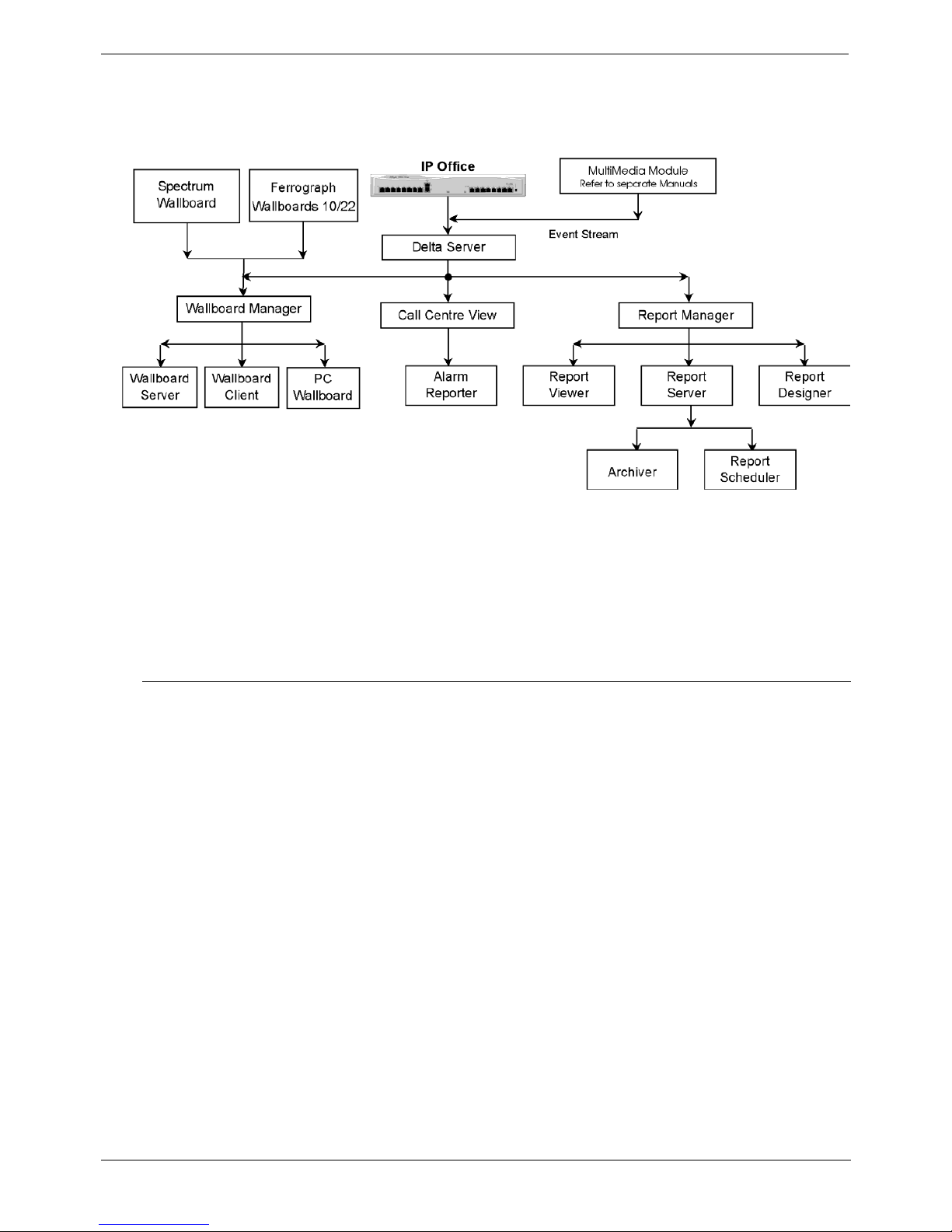
Compact Contact Center (CCC) modules provide the user with the necessary tools to
facilitate the management of call traffic. They are designed to provide a tightly
integrated real time and historic reporting package and wallboard support for the
eBusiness digital communications platform. The product consists of a set of fully
integrated modules sharing a common database utilizing Interactive Directory and
Database (IDD) technology.
The suite of modules consists of the following applications:
• Call Center View (CCV):
Provides a management package for telephone based staff and supports any size
Customer Facing Department (CFD) or contact center. To effectively control
customer service levels, real time human resource management is essential and
the Call Center View has been specially designed to manage the CFD’s or contact
center’s most valuable and expensive asset – it's people.
• Call Center View Alarm Reporter:
Provides information (for each Contact Center Profile) about alarms that have
occurred within the Compact Contact Center. The detailed alarm information for
each directory number is presented in report format, which can then be printed.
• Wallboard Manager:
Real time information from the call center is essential to react to constantly
changing telephone traffic levels and provide excellent customer service.
Wallboards allow managers and staff to monitor the service being provided and
respond immediately. Wallboards provide current information on the number of
calls waiting, response times and service levels. Wallboard Manager provides the
ability to drive Ferrograph and Spectrum physical wallboards and PC wallboards.
• PC Wallboard:
The PC Wallboard delivers traditional wall mounted wallboard functionality to the
desktop but with the additional benefit of each PC Wallboard agent being able to
configure and monitor a personalized view of the contact center. The PC
Wallboard also enables agents to increase their productivity and maintain revenue
levels with the added benefit of managing customer callback requests.
• Report Manager:
Provides in depth historical reporting on CFD or contact center activity. In addition
to call information, the Report Manager also reports agent activity. This powerful
package allows individual call records to be stored and reported upon months
later.
Compact Contact Center Installation Manual General - Page 5
40DHB0002USBG Issue 4a (05/29/2003) Introduction

Page 6 - General Introduction
• CCC User Access:
CCC User Access allows storage of personal Call Center View and Wallboard
settings. It also establishes user rights and password protection for Call Center
View, Wallboard and Alarm Reporter software.
• Workforce Management – Blue Pumpkin:
Workforce Management Interface allows integrated rostering, forecasting and
scheduling systems to connect across the LAN to a comma separated variable
(CSV) file containing a list of Contact Center related metrics.
• MultiMedia Module:
MultiMedia Module (MMM), is a customer contact software solutions that enables
companies and departments to manage multimedia contacts into and out of the
organization. MMM provides applications that manage Telephony, Web Chat, Email and Web Call Back communications.
For installation of MultiMedia Module, refer to the separate Installation Manual.
Report Designer:
The Report Designer module is a separate product that is used in conjunction with
Report Manager and is a software tool used for querying and reporting. It enables the
user to create reports that contain data from their contact center database and
schedule reports to be updated and printed. Report Designer is stalled when Report
Client is installed but requires a licence to operate. Refer to the separate CCC
Installation and CCC Report Designer User's Manuals for details.
Page 6 - General Compact Contact Center Installation Manual
Introduction 40DHB0002USBG Issue 4a (05/29/2003)

Introduction Use of this Manual - Page 7
Use of this Manual
This manual covers the installation and administration of Avaya's Compact Contact
Center (CCC) at software Level 4.0+. on the following communications platforms:
• IP403/406/412 Office platforms operating Software Level 1.4+
This guide is intended for use by installers and administrators who are familiar with the
relevant communications platform and have successfully completed the appropriate
training courses.
Ensure that you have read and understood this Manual before beginning
installation.
About this Manual
This manual provides the information necessary to set up, install and perform basic
set-up on CCC modules. The following overview defines the sequence of actions that
must be performed to install CCC modules:
1. Check both the hardware and software specifications for all Server/Client PCs (see
page 11).
2. Configure the Server and Client PCs (see page 14).
3. Install the required CCC applications on the Server, Client and Agent PCs
(see page 27).
4. Allocate CCC User Access rights (see page 42).
5. Set up the Delta Server (see page 43).
6. Define and set up the IP Office requirements (see page 44).
7. Install the CCC Licenses on the IP Office (see page 44).
8. Install the Wallboards (see page 49).
9. Set up and start the Workforce Management Interface (optional - see page 65).
10. Upgrade the Database to SQL 2000 (optional - see page 66).
Once installation has been completed, the following manuals provide the details for
administrating and operating the CCC.
• CCC System Administrator's Manual
• CCC System Supervisor's Manual
Compact Contact Center Installation Manual Use of this Manual - Page 7
40DHB0002USBG Issue 4a (05/29/2003) Introduction
Page 8 - Overview of CCC Introduction
Overview of CCC
Avaya's Compact Contact Center (CCC) provides the user with the necessary tools to
facilitate the management of call traffic. The diagram below shows the concept:
Installation of CCC on IP Office requires licenses to enable the various modules (see
page 44). For systems of up to15 agents* the CCC modules can be installed on a
stand-alone Server PC (see page 8). For systems of more than15 agents the Server
and Client functions must reside on separate PCs (see page 10).
*Note: An AGENT is defined as a person who makes or receives calls and has
'logged on' to the system, e.g. has a ‘forced log on’ status on the switch.
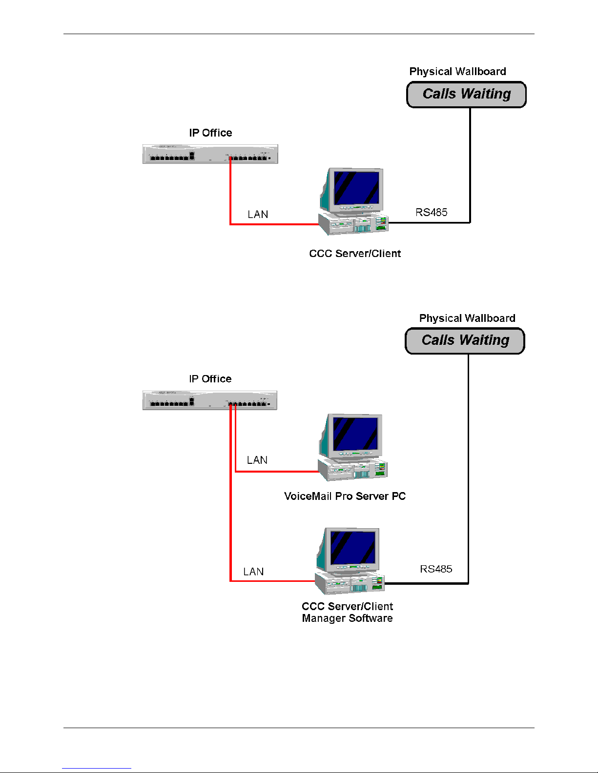
Fifteen Agent Systems and below
The Compact Contact Center Manager comprises a suite of tightly integrated modules
installed on a Server PC platform running Windows 2000 or NT4. The CCC Manager
may be installed either with or without Voice Mail Pro. The following lists the modules
included within the CCC Manager which are designed to run concurrently on the Server
PC:-
CCC Server PC
• Delta Server
• Call Center View
• PC Wallboard
• Wallboard Server*
• Report Manager
• Report Server and Client
• Report Designer (optional)
• CCV Alarm Reporter
• Voice Processing Administration (if Voice Mail Pro is present).
*Note: Wallboard Server and Client should not be installed on the same PC.
If client is on the Server, there is no need to install Wallboard Client.
Page 8 - Overview of CCC Compact Contact Center Installation Manual
Introduction 40DHB0002USBG Issue 4a (05/29/2003)
Introduction Overview of CCC - Page 9
The following diagram shows the Compact Contact Center connectivity (for systems of
15 agents and below) without a Voice Mail Pro.
The following diagram shows the Compact Contact Center Manager connectivity (for
systems of 15 agents and below) with a Voice Mail Pro present.
Compact Contact Center Installation Manual Overview of CCC - Page 9
40DHB0002USBG Issue 4a (05/29/2003) Introduction
Page 10 - Overview of CCC Introduction
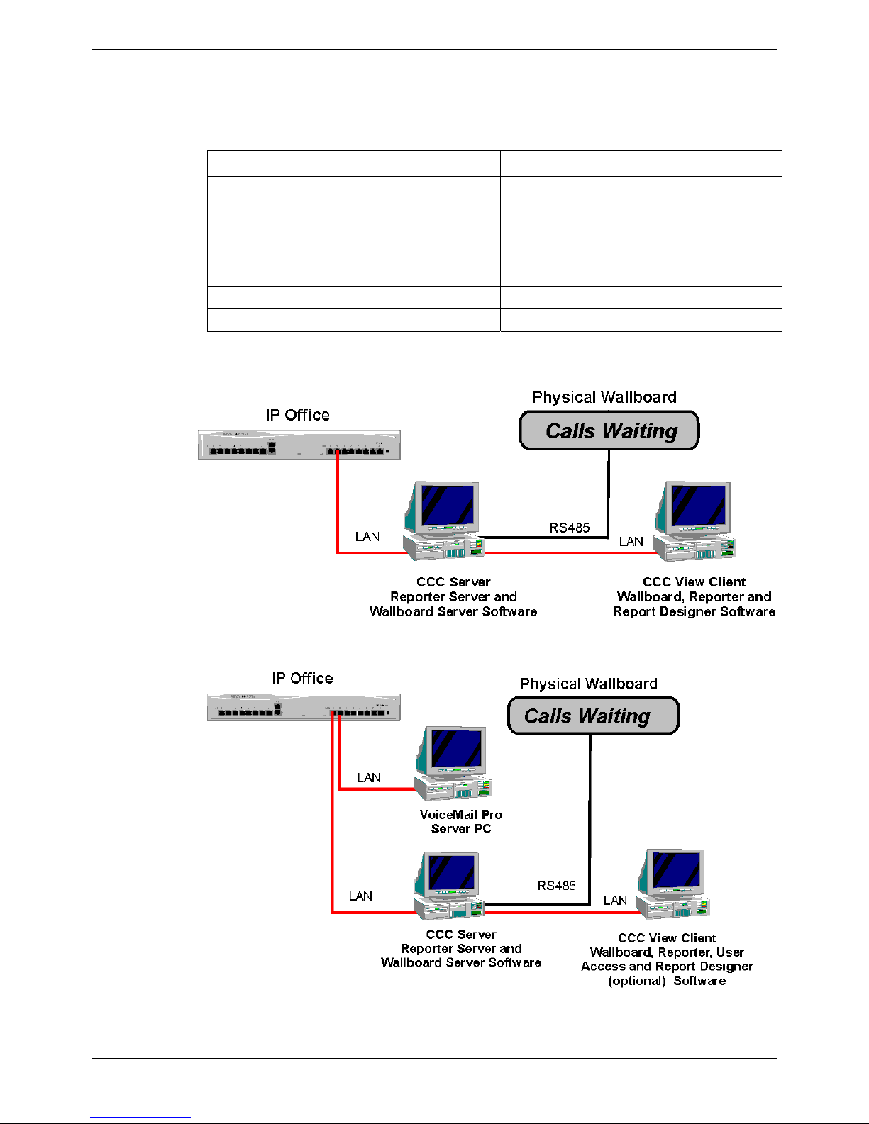
Systems above fifteen Agents
Due to the traffic demands of contact centers above 15 agents, both the Report Server
and Wallboard Server must reside on the same dedicated PC. The Compact Contact
Center Manager supports 5 concurrent supervisor positions. It may be installed either
with or without a Voice Mail Pro. The following details where the applications reside:
Client PC Server PC
Call Center View Delta Server
Wallboard Client Report Manager
Report Viewer Wallboard Server
Report Designer (Optional) Report Scheduler
PC Wallboard Archiver
CCV Alarm Reporter Database Server Supervisor
CCC User Access Workforce Management (Optional)
The diagram below shows the Compact Contact Center Manager without a Voice Mail
Pro being installed.
The diagram below shows the Compact Contact Center Manager with a Voice Mail Pro
present.
Page 10 - Overview of CCC Compact Contact Center Installation Manual
Introduction 40DHB0002USBG Issue 4a (05/29/2003)

Introduction System Specifications - Page 11
System Specifications
The Server PC will support up to five Clients, i.e. five PC's running Client applications.
The Operating System on the Server PC can be either Windows 2000 server or
Windows NT Server 4.0.
The Operating System of the Client PCs can be either Windows NT Workstation 4.0,
Windows 98 or Windows 2000 Professional.
Computer Systems
Each Server PC and Client PC must meet the minimum requirements as follows:-
Server PC: (Supporting Max 5 Clients):
• Pentium 800MHz or higher, with 1 x 10GByte hard disk. (The Server PC requires a
4 GB partition for the software applications. The remainder of the hard drive is
used for the Archiver database.)
• Minimum 256 Mbytes of RAM
Client PC:
• Pentium 450MHz or higher, with >1GByte hard disk (4GBytes recommended when
using MMM application)
• Minimum 128 Mbytes of RAM
Monitor: 15" (or optional 17") SVGA supporting 800x600
Keyboard: Win NT/98/2000 Compatible
Floppy Disk Drive A: 3.5
"
1.44 Mb high density
CD ROM Drive
Backup Device: On Stream 30GB Digital Drive (optional).
Expansion Cards
• Wallboard Comms Card: Advantech PC-LabCard (Model PCI – 1601A) for
Ferrograph 10/22 Wallboards.
Compact Contact Center Installation Manual System Specifications - Page 11
40DHB0002USBG Issue 4a (05/29/2003) Introduction
Page 12 - System Specifications Introduction
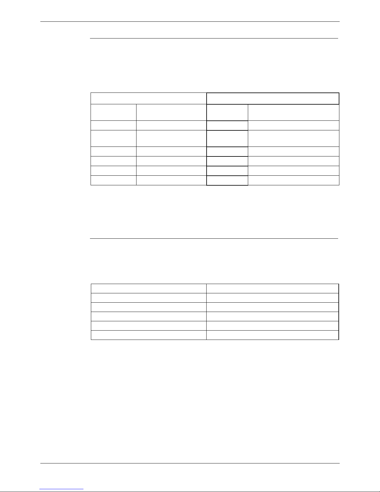
Software Requirements for CCC Server(s)
The Microsoft software components for Windows NT and 2000 Servers are listed in the
following table and must be installed prior to installing a CCC Server PC.
Windows NT Server 4.0 Windows 2000 Server
Win NT 4.0 Server Win 2000 Server
Win NT 4.0 SP6 Win 2000 Server SP3
MS Internet Explorer 5.5 MS Internet Explorer 5.5
Database Solution
MSDE / MSDE 2000 (SP3)
SQL7
SQL 2000
Database Solution
MSDE / MSDE 2000 (SP3)
SQL7
SQL 2000
Windows Critical Updates Windows Critical Updates
Software Requirements for CCC Client(s)
The following table lists the software that must be installed on an CCC Client prior to
installing a CCC Client PC.
Software Comment
Windows 98/ME/NT WS/2000 Pro/XP Pro
MS Internet Explorer 5.5 Full installation
Windows Critical Updates Windows Critical Updates
E-mail Server Requirements
For CCC applications that utilize e-mail functionality, an e-mail server (extended MAPI
compliant) must be either installed on a separate PC or access must be available to an
e-mail server. In both cases you must obtain and record the following (you will need
this data for setting-up the mailboxes on PCs running CCC applications):-.
Parameter Data
E-mail Server name
CCC Server Mailbox name
CCC Clients Mailbox names (up to 5 off)
CAUTION: Do not install the e-mail server on the CCC Server PC.
Page 12 - System Specifications Compact Contact Center Installation Manual
Introduction 40DHB0002USBG Issue 4a (05/29/2003)
Introduction System Specifications - Page 13
Wallboard Devices
Ferrograph Wallboards 10 and 22
The Wallboard 10 is a single line display consisting of 10 tri-color characters.
The Wallboard 22 is a two line by 22-character tri-color Wallboard.
Both wallboards are connected, via a multi-drop circuits, to the host PC running the
Wallboard Server application.
Specifications
Ferrograph Wallboard 10 Ferrograph Wallboard 22
Voltage Check label on rear of
wallboard
Voltage 220/240V AC OR 110V AC.
(Check label on rear of wallboard)
Wattage 35W Wattage 108W
Cold Start
Inrush Current
30A for up to 6ms Cold Start
Inrush Current
30A for up to 6ms
Baud Rate 9600 only Baud Rate 9600 only
Input RS 485 Input RS 485
Weight 4 kg Weight 6 kg
Dimensions L 469 x D 75 x H 123 mm Dimensions L 1097 x D 75 x H 198 mm
Installation power distribution circuit rating to be greater than 6 amp. Any circuit
breakers must be capable of handling the cold start inrush current without tripping.
For details of Ferrograph Wallboard installation see page 49.
Spectrum 4120C Wallboard
The Spectrum 4120C is a two line 20-character tri-color wallboard. It is connected via a
multi-drop circuit to the host PC running the Wallboard Server application.
Specifications
Voltage Check label on rear of wallboard
Wattage 150W
Baud Rate 9600 only
Input RS 485
Weight 8.4 kg
Dimensions L 1021 x D 129 x H 196 mm
Spectrum Wallboards can be ‘daisy-chained’; this will required the use of the Spectrum
Remote Controller to enable serial addressing. For this and the Wallboard
specifications, safety statements, wall mounting instructions, etc., refer to the
documentation supplied with the Wallboard.
Caution: Connection to the PC must only be made via the Wallboard's RS485
socket.
Compact Contact Center Installation Manual System Specifications - Page 13
40DHB0002USBG Issue 4a (05/29/2003) Introduction

Page 14 - Overview PC Configuration
PC Configuration
Overview
Before installing CCC module you must install/access an e-mail server, obtain e-mail
server name and mailbox names, re-configure the Server and Client PC for guest
accounts, partition the server drive, install a database application, etc. The Server and
Client PCs must be given dedicated names.
The following details the required actions and must be performed in sequence before
installation of CCC modules is attempted:-
• Check that all system specifications (both hardware and software) have been
fulfilled. See page 11.
• Server PC configuration using Windows NT 4.0 Server. See page 15.
or
• Server PC configuration using Windows 2000. See page 21.
• Client PC configuration using Windows NT 4.0 Workstation. See page 24.
or
• Client PC configuration using Windows 98. See page 25.
or
• Client PC configuration using Windows 2000. See page 26.
Both the Server and client PCs must be re-configured before installation on the CCC
modules.
Page 14 - Overview Compact Contact Center Installation Manual
PC Configuration 40DHB0002USBG Issue 4a (05/29/2003)

PC Configuration Server PC Setup – NT4 - Page 15
Server PC Setup – NT4
Windows NT Server 4.0 Modifications
On a machine with Windows NT4 already installed, you must perform all of the
following in sequence before installation of CCC modules:-
1. Give the Server PC a dedicated name (see page 16).
Record this name as you will need it for the Delta Server and Database Server
entries when you install the CCC modules.
2. Share the C drive, amend the Event Log settings and create a password protected
User Guest account (see page 15).
3. The drive must be partitioned to create space for the database (see page 17).
4. The database application must be installed (see page 18).
5. The Wallboard cards must be installed (see page 19).
6. The network protocol must be set to TCP/IP.
7. Windows NT Server Service Pack 6a must have been installed.
If you are in doubt, install the service pack again.
8. Ensure that the Regional Settings are correct [e.g. for USA set it to English (United
States)] and that the Time is set to local time.
9. Make sure that the screen display properties have been set to the following:
• Desktop Area is set to 800 by 600 pixels.
• Color palette is set to 65536.
Share the C drive
1. Double click on the My Computer Icon.
2. Right mouse click on drive C: and select Sharing from the menu.
3. Click on the New Share button.
4. Enter C (Uppercase) in the Share name and ensure that the user limit is set at
Maximum Allowed.
5. Click on the OK button to close the screen.
6. Click on the Apply button and then the OK button.
Note: If Installing CCC in connection with the MMM on separate servers. Please
ensure you have a mapped network drive connection to the MMM Server from the
CCC Server.
User Guest Account
1. Click Start, highlight Programs and then Administrative Tools.
2. Click on User Manager for Domains.
3. From User select New User. Enter a Username, Full Name and Description
(optional). Enter and confirm a Password. Record and store this in a safe place as
this will be required by Client PCs.
Remove the tick from the check box of "Account Disabled".
4. Click OK and then close the User Manager for Domains screen.
Event Log Settings
The Event Log settings need to be amended otherwise the PC will probably run out of
disk space.
1. Click Start, highlight Programs and then Administrative Tools.
2. Click on Event Viewer. Click Log and then Log Settings.
3. Select System from the drop down list. Select Overwrite Events as needed.
4. Select Security from the drop down list. Select Overwrite Events as needed.
5. Select Application from the drop down list. Select Overwrite Events as needed.
6. Click OK and exit the Event Viewer.
Compact Contact Center Installation Manual Server PC Setup – NT4 - Page 15
40DHB0002USBG Issue 4a (05/29/2003) PC Configuration

Page 16 - Server PC Setup – NT4 PC Configuration
Change NT4 Server PC Name
Make sure that there are no programs running on the Server then follow the
instructions below.
1. From the Windows Taskbar, click Start, point to Settings and select Control
Panel, double click Network.
2. From the Identification tab click Change.
3. Type your computer name as required (do not includes spaces in the name, e.g.
ACMESERVER). Click OK.
4. From the Identification tab, click OK to confirm.
5. When prompted, click Yes to restart the PC.
6. If you are using MSDE you will need to re-install it (see page 18). Alternatively, if
you are using SQL 2000 continue from the next step.
7. From the Windows Taskbar, click Start, point to Programs, select SQL Server,
and then select SQL Query Analyzer.
8. Enter the new PC name in the SQL Server field (e.g. ACMESERVER).
9. Select the SQL Server Authentication option and enter sa as the Login name,
leaving the password field empty.
10. Click OK
11. Execute the following command:
sp_dropserver ACMESERVER
12. Execute the following command:
sp_addserver # # # # # # # # # #,LOCAL
(e.g. if the server PC has been renamed as ACMESERVER enter sp_addserver
ACMESERVER,LOCAL.)
13. Re-boot the Server PC.
It is not necessary to change the ODBC setting as these are automatically configured
by the CCC. However, if you wish to use another Database Server, open the ODBC
settings and remove, if entered, remove the SDXArchiver and SDX Repository entries
(see page 16).
Connect to another Database Server
To connect to another Database Server, you must first remove both the SDXArchiver
and SDXRepository entries from the ODBC settings of this Server.
1. From the Windows Taskbar, click Start, point to Settings and select Control
Panel.
2. From the Control Panel, open ODBC, and click System DSN tab. The ODBC Data
Source Administrator screen appears.
3. Select SDXArchiver and then click Remove.
4. Select SDXRepository, click Remove and the OK.
5. After CCC modules have been installed (see page 67), with Delta Server running,
open Report Viewer and, when prompted on the Connect to database server
screen, enter the name of the required Server and click OK.
Page 16 - Server PC Setup – NT4 Compact Contact Center Installation Manual
PC Configuration 40DHB0002USBG Issue 4a (05/29/2003)
PC Configuration Server PC Setup – NT4 - Page 17
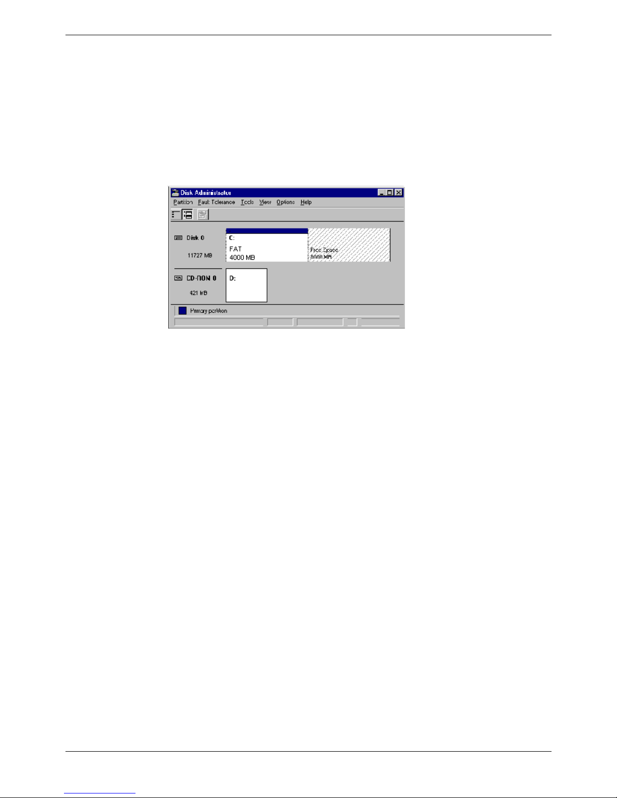
Partition the Disk
The NT Server disc drive must be partitioned to create a location for the database.
1. From the Windows Taskbar, click Start, point to Programs, point to
Administrative Tools (Common) and click Disk Administrator.
2. If you are running this application for the first time, a warning screen will show
stating that the system configuration will now be updated. Click Ok to continue.
Click Ok to the confirmations.
3. A graphical representation of all the physical disks connected to your computer,
along with their partitions, appears. A status bar at the bottom of the window
provides basic information on partitions. A color-coded legend on top of the status
bar shows what the different partition colors and patterns represent.
4. Right click the D drive (i.e. CD-ROM).
5. From the Tools menu, click Assign Drive Letter.
6. Click to select Assign Drive Letter, and select letter E.
7. Click OK.
8. From the Confirmation screen, click Yes to continue.
9. From the Partition menu, select Create. Click Yes to continue and create the
partition. The Create Primary Partition screen displays the size of the partition to
be created. This will usually be the maximum since it will contain all of the free
space available. Click OK.
10. From the Partition menu, select Commit Changes Now. Click Yes to save the
changes.
11. Click Yes to save the changes.
12. Click OK to update the Emergency Repair configuration and create a new
Emergency Repair Disk.
13. Click the D drive (the remaining partition on Disk 0). From the Tools menu, click
Format. Set File System to NTFS. Click Start to initiate the format request and
then click OK to continue.
14. When the formatting is finished, click OK.
15. From the Format D:\ screen, click Close to return to the Disk Administrator
window.
16. From the Partition menu, click Exit to close the Disk Administrator application.
17. Install the database application (see page 18).
Compact Contact Center Installation Manual Server PC Setup – NT4 - Page 17
40DHB0002USBG Issue 4a (05/29/2003) PC Configuration

Page 18 - Server PC Setup – NT4 PC Configuration
Install Database Application
If SQL 2000 is to be installed instead of MSDE, please go to the section Installing
Microsoft SQL 2000 tools on page 18.
Note: The Server PC's hard drive must have been partitioned before installing the
database application (see page 17).
Installing MSDE 2000
1. Insert the CCC Installation CD into the drive.
2. From the Windows taskbar click Start, select Run and then click on the Browse
button.
3. View the CD drive and double click the MSDE folder. Select MSDEsp3.exe and
click on the Open button.
4. Click the OK button to continue.
5. Select the required language for the installation and then click on the OK button.
The installation could take up to 20 minutes.
6. Once the setup is complete, reboot the PC when requested.
Installing Microsoft SQL 2000 tools
It is possible to install SQL 2000 instead of MSDE. The software is not supplied as part
of CCC and you will need to purchase your own copy.
The following steps will install SQL Server 2000 tools:
1. Insert the SQL Server 2000 compact disc into your CD-ROM drive. If the compact
disc does not auto run, double-click Autorun.exe in the root directory of the
compact disc.
2. Select SQL Server 2000 Components, select Install Database Server, and then
setup prepares the SQL Server Installation Wizard. If not installing on Windows NT
Server version 4 or Windows 2000 Server a warning message will be displayed
stating that only client components will be available. Click OK. At the Welcome
screen, click Next.
3. In Computer Name dialog box, Local Computer is the default option and the
local computer name appears in the edit box. Click Next.
4. In the Installation Selection dialog box, click Create a new instance of SQL
Server, or install Client Tools, and then click Next.
5. Enter the User Information. Click Next.
6. Click Yes to accept the software license agreement.
7. Enter the 25 digit CD-Key. Click Next.
8. In the Installation Definition dialog, select Client Tools Only.
9. In the Select Components dialog, select the desired components. It is
recommended that you have Management Tools and Client Connectivity
options selected. Click Next.
10. In Start Copying Files dialog box. Click Next.
11. In the Setup Complete dialog box, click Finish.
12. Install the SQL 2000 Service Pack 3.
If Ferrograph Wallboards are to be installed, proceed from page 19. Otherwise, you
must now configure the Client PCs (see pages 24, 25, 25 and 26 as appropriate).
Alternatively, where Server and Client are on the same PC, you may now install the
appropriate CCC licenses and applications (see pages 44 and 27 respectively).
Page 18 - Server PC Setup – NT4 Compact Contact Center Installation Manual
PC Configuration 40DHB0002USBG Issue 4a (05/29/2003)

PC Configuration Server PC Setup – NT4 - Page 19
Installation of Wallboard Card (Ferrograph only)
Ensure that the Wallboard Card's switches and jumper setting are as listed below. The
location of the switches and jumpers is detailed in the Installation Manual that should
be supplied with the PCB. If the Installation Manual is not supplied with the PCB it can
be obtained from www.advantech.com.
Advantech ISA Wallboard Card Installation
Card Settings: -
JP1 (ch#1) 485
JP2 (ch#2) 485
JP3 (ch#1) IRQ9
JP4 (ch#2) IRQ5
JP5 (ch#1) On
JP6 (ch#2) On
To change the settings on Windows NT PC:
1. Click Start, highlight Settings and then click Control Panel.
2. Double click the Ports icon.
3. Highlight Port 3 and then click Settings.
4. At the next screen click Advanced.
5. Change Base I/O port address to 03E8.
6. Change IRQ to 5, then click OK.
7. Click Don't restart Now and then click on OK.
8. Highlight Port 4 and click on Settings.
9. At the next screen click on Advanced.
10. Change Base I/O Port Address to 02E8.
11. Change IRQ to 9 and then click OK.
12. Click Restart Now.
To change the settings on Windows2000 Pro:
1. Right click on My Computer and select Manage.
2. Open Ports (COM & LPT), highlight required port and right click.
3. Select Properties and then click on the Resources tab.
4. Remove the tick from Use automatic settings.
5. Highlight Interrupt Request and select Change Settings.
6. From the Setting based on pull down menu set IRQ to 5.
7. Highlight Input/Output Range and select Change Settings.
6. From the Setting based on pull down menu select 03E8, then click OK.
Compact Contact Center Installation Manual Server PC Setup – NT4 - Page 19
40DHB0002USBG Issue 4a (05/29/2003) PC Configuration

Page 20 - Server PC Setup – NT4 PC Configuration
Advantech PCI Wallboard Card
Card settings: SW1 (CH1) = ON
SW1 (CH2) = ON
JP1 = 485
JP2 = 485
To change the settings (NT systems):
1. Ensure that the card is not plugged into the PC. If the card is still in the PC shut
down the PC and remove the power leads before removing the card, otherwise the
hard drive may become corrupted.
2. Insert the Advantech PCI drivers utility installation diskette 1 into drive A.
3. Select Start, and then click on Run.
4. At the next screen type A:\setup.exe and click on OK.
5. At the welcome screen click Next.
6. At the software license screen agreement screen click Yes.
7. At the destination screen accept the defaults and click Next.
8. At program folder accept the defaults and click Next.
9. When prompted insert disk 2 and click on the OK button.
10. At set-up complete screen and click Finish.
11. At Advantech PCI serial Service Manager screen make sure that the Start/Stop
service control is Install and Start Service and then click OK.
12. Click OK at the next screen.
13. Shut down the computer and install the card into PCI SLOT 4.
To change the settings (Win2000 systems):
1. Ensure that the card is not plugged into the PC. If the card is still in the PC shut
down the PC and remove the power leads before removing the card, otherwise the
hard drive may become corrupted.
2. Insert the CCC CD, do not let it auto run but simply open the CD
3. Locate and open the folders PRIRS485 card drivers for WIN2K/ICOM_DRV and
click on SETUP.EXE.
4. At the welcome screen click Next.
5. At the software license screen agreement screen click Yes.
6. At the destination screen accept the defaults and click Next.
7. At program folder accept the defaults and click Next.
8. When prompted insert disk 2 and click on the OK button.
9. At set-up complete screen and click Finish.
10. At Advantech PCI serial Service Manager screen make sure that the Start/Stop
service control is Install and Start Service and then click OK.
11. Click OK at the next screen.
12. Shut down the computer and install the card into PCI SLOT 4.
If applicable (Server and Client on different PCs), you must now configure the Client
PCs (see pages 24, 25, 25 and 26 as appropriate). Alternatively, where Server and
Client are on the same PC, you may now install the appropriate CCC licenses and
applications (see pages 44 and 27 respectively).
Page 20 - Server PC Setup – NT4 Compact Contact Center Installation Manual
PC Configuration 40DHB0002USBG Issue 4a (05/29/2003)

PC Configuration Server PC Setup – Windows 2000 Pro - Page 21
Server PC Setup – Windows 2000 Pro
Windows 2000 Modifications
On a machine with Windows 2000 already installed you must perform all of the
following in sequence before installation of CCC modules:-
1. Give the Server PC a dedicated name (see page 23). Record this name as you will
need it for the Delta Server and Database Server entries when you install the CCC
modules.
2. Create the C Share, User Guest Account and Event Log settings
(see page 21).
3. The drive must be partitioned to create space for the database (see page 22).
4. The database application must be installed (see page 18).
5. The Wallboard cards must be installed (see page 19).
6. The network protocol must be set to TCP/IP.
7. Ensure that the Regional Options are set [e.g. for USA set it to English (United
States)] and that the Time is set to local time.
8. Make sure that the screen display properties have been set to the following:
• Desktop area is set to 800 by 600 pixels.
• Color palette is set to True Color (32 Bit).
Share the C drive
1. Double click on the My Computer Icon.
2. Right mouse click on drive C: and select Sharing from the menu.
3. Click on the New Share button.
4. Enter C (Uppercase) in the Share name and ensure that the user limit is set at
Maximum Allowed.
5. Click on the OK button to close the screen.
6. Click on the Apply button and then the OK button.
Note: If Installing CCC in connection with the MMM on separate servers. Please
ensure you have a mapped network drive connection to the MMM Server from the
CCC Server.
User Guest Accounts
For CCC applications to communicate, the Guest Account on Windows 2000 needs to
be enabled. To modify the Guest Account:
1. Right mouse click on the My Computer Icon. Select Manage.
2. Expand the folder Local Users and Groups.
3. Open the Users folder, right click on Guest and select Set Password.
4. Enter and confirm the Guest Account password. Record and store in a safe place
as this will be need by client PCs when they log on.
5. Double click on Guest and select the General Tab.
6. Remove the tick by 'Account is disabled' then click on the Apply button.
7. Click on Close and then close all screens.
Event Log Settings
The Event Log settings are altered through the Windows Event Viewer. To do this:
Compact Contact Center Installation Manual Server PC Setup – Windows 2000 Pro - Page 21
40DHB0002USBG Issue 4a (05/29/2003) PC Configuration
 Loading...