

Page 1

Nortel Business Communication Manager 5.0
Configuration — Devices
Release: 5.0
Document Revision: 02.04
NN40170-500
Page 2

Document status: Standard
Document issue: 02.04
Document date: August 2009
Product release: BCM 5.0
Job function: Configuration
Type: Technical Publication
Language type: English
Copyright © 2009 Nortel Networks
All Rights Reserved.
NORTEL, the globemark design, and the NORTEL corporate logo are trademarks of Nortel
Networks.
Page 3

Contents
Contents 3
New in this release 11
Features 11
Introduction 13
Device configuration overview 15
Configuration methods 15
Dynamic Device Configuration for BCM450 16
Features and applications 16
System feature codes 17
Lines and numbers 17
Default memory button programming for sets 18
Telephony features 19
Call answer features 19
Call answer privacy features 21
Dynamic Device Configuration 11
Call logs 11
Find Me/Follow Me 11
Professional Call Recording 12
16
Applications overview 16
DN records parameters 17
Analog set customization 17
IP phone line configuration 18
Proactive Voice Quality Monitoring 18
Hot desking IP phone configuration 18
Rules of default button assignment 19
Handsfree and handsfree answerback 20
Call queuing 20
Directed pickup 20
Pickup groups 20
Trunk answer 20
Answer DNs 21
Copyright © 2009 Nortel Networks
Nortel Business Communication Manager 5.0
Configuration — Devices
NN40170-500 02.04 Standard
August 2009
Page 4

4 Contents
Automatic privacy enable 21
Do not disturb (DND) 21
Intrusion controls 21
Call hold features 21
Call hold 21
Automatic call hold (autohold) 22
Exclusive call hold 22
Parking and transferring calls 22
Call transfer 22
Line redirection 22
Call forward 23
Camp-on 23
Call park 23
Callback 23
Call sharing, call park, and SWCA buttons 24
Call information 24
Call display information 24
Call duration timer 24
Time and date display 24
Malicious caller ID (MCID) 24
Call log 25
LogIt 25
Feature configuration: calling features 25
Set-to-set messaging 25
Set-to-set display messaging 25
Paging and paging constraints 25
Button programming 26
Special features for sets 26
Hotline telephone 26
Control telephone 26
Supervisor telephone 26
Central answering position 27
System-Wide Call Appearance 29
SWCA overview 29
Use of Hold with SWCA keys 30
Temporarily parked calls 30
Key availability and programming 31
SWCA-feature interaction 31
Timed out SWCA calls 31
Outbound calls 31
SWCA and auto hold 31
SWCA and call transfers 31
SWCA and conference calls 31
Set Template Programming 32
Copyright © 2009 Nortel Networks
Nortel Business Communication Manager 5.0
Configuration — Devices
NN40170-500 02.04 Standard
August 2009
Page 5

Contents 5
Set template administration 32
Template-to-set assignment 33
Template import and export capability 34
Set template creation 34
Set association 35
Voice mailbox setup 35
Set and line renumbering 35
System parameter configuration 37
Accessing system identification 37
Setting date and time 38
Synchronize system with an NTP Server or trunk 39
Setting clock control to local system 40
System scheduled services 40
Configuring schedule name and timers 40
Configuring scheduled service 42
Basic parameters for analog sets and devices configuration 45
Configuring analog telephones 46
Assigning a line to an analog telephone 47
Adding line assignments and line pools for analog telephones 48
Configuring set capabilities and user preferences for analog telephones 49
Configuring telephone capabilities for analog telephones 49
Programming outgoing call restrictions for analog telephones 51
Setting restriction filters for analog telephones 51
Setting line/set restrictions for analog telephones 52
Assigning pause for external dialing for analog devices 52
Basic parameters for digital sets configuration 55
Configuring digital telephones using the DN panels 56
Assigning a line to a digital telephone 56
Adding line assignments and line pools to digital telephones 58
Configuring set capabilities and preferences for digital sets 59
Configuring digital telephone capabilities 61
Configuring preferences for a digital telephone 63
Programming digital telephone memory buttons 63
Programming user speed dials for digital telephones 65
Programming outgoing call restrictions for digital telephones 65
Setting restriction filters for digital telephones 66
Setting line/set restrictions for digital telephones 66
IP phone configuration 67
Configuring IP telephones 68
Assigning a line to an IP telephone 68
Adding line assignments and line pools to IP telephones 69
Configuring set capabilities and preferences for IP sets 70
Copyright © 2009 Nortel Networks
Nortel Business Communication Manager 5.0
Configuration — Devices
NN40170-500 02.04 Standard
August 2009
Page 6

6 Contents
Configuring IP telephone capabilities 71
Configuring preferences for an IP telephone 72
Telephone relocation 75
Digital telephone relocation 75
Keeping an IP telephone active 76
IP telephone relocation without changing the DN 76
IP telephone relocation with a changed DN 76
Central answering positions configuration 79
Configuring CAP assignments (eCAPs) 79
Creating CAP stations 79
Programming CAP/KIM buttons 80
Programming module buttons 80
Hunt Group configuration 81
Configuring Hunt Group general settings 81
Adding members to Hunt Groups 85
Deleting members from Hunt Groups 85
Changing order of members in Hunt Groups 86
Assigning lines to Hunt Groups 86
Deleting lines from Hunt Groups 87
External Hunt Group calls monitoring 89
Using a silent monitor 89
Hospitality system configuration 91
Setting up a hospitality system 91
Assigning a room to a set 92
Deleting a room assignment from a set 92
Setting call restrictions (by room) 93
Programming wake-up services (by room) 93
Global VoIP features 95
Setting up feature access 95
Configuring IP features list 95
Accessing features through Services button 96
Defining a key label for a feature 96
Using the Hot desking feature 97
Setting up a password for Hot desking 97
Resetting the Hot desking password 98
Diverting an IP phone configuration 98
Cancelling Hot desking from the diverted phone 99
Cancelling Hot desking from the target phone 99
Configuring a new time zone on a remote IP phone 99
Downloading firmware 100
Forcing firmware download to a Nortel IP phone 100
Copyright © 2009 Nortel Networks
Nortel Business Communication Manager 5.0
Configuration — Devices
NN40170-500 02.04 Standard
August 2009
Page 7

Contents 7
Telephony features configuration 103
Telephony features configuration procedures 103
Configuring telephony features navigation 103
Adjusting contrast through Element Manager 104
Adjusting contrast through the telephone set 104
Adjusting contrast through the telset interface 104
Configuring the call dialing method through Element Manager 105
Configuring the call dialing method through the telephone set 105
Configuring the call dialing method through the telset interface 106
Configuring the language in the display through Element Manager 106
Configuring the language in the display through the telephone set 107
Adjusting the receiver volume through Element Manager 107
Adjusting the receiver volume through the telephone set 107
Configuring the auxiliary ringer (option) 108
Enabling and disabling the auxiliary ringer for lines 108
Enabling and disabling the auxiliary ringer for telephones 108
Enabling and disabling the auxiliary ringer for ring groups 108
Enabling and disabling the auxiliary ringer for hunt groups 109
Set access to call answer features configuration 111
Configuring for calls direct to set 112
Configuring handsfree and handsfree answerback 112
Configuring for calls not direct to set 113
Configuring call queuing 113
Configuring Directed Pickup 113
Adding a set to a pickup group 114
Configuring for answering any call 114
Assigning a set to a ring group 114
Creating a ring group schedule 115
Configuring ring group line settings 115
Blocking set access to trunk answer 117
Configuring answer DNs 117
Defining which calls must alert answer DNs 117
Assigning an answer DN to a set 118
Configuring privacy 118
Allowing do not disturb on a set 119
Blocking set access to the DND feature 119
Configuring privacy for a physical line 119
Programming a line to automatically enable privacy 120
Intrusion controls configuration 120
Configuring intrusion controls 120
Configuring call hold 121
Configuring full autohold on a line 121
Configuring autohold on a set 121
Copyright © 2009 Nortel Networks
Nortel Business Communication Manager 5.0
Configuration — Devices
NN40170-500 02.04 Standard
August 2009
Page 8

8 Contents
Configuring call transfer 122
Configuring transfer of unanswered calls 122
Configuring Callback 122
Configuring call redirect 123
Allowing call redirect 123
Programming call redirection on a line 124
Adjusting the call redirect tone 124
Configuring call forward 124
Configuring forwarding of unanswered calls 125
Blocking set access to call forwarding 125
Configuring the call camp-on timer 125
Configuring call park 126
Setting up the call park access code 126
Setting up park timeout 127
Determining call park code assignment sequence 127
Sharing calls by parking on SWCA buttons 127
Allowing Malicious Caller ID (ETSI ISDN) 131
Configuring call logs 132
Resetting the call log space 132
Setting call log options 133
Resetting call log password 134
Set access to calling feature programming 137
Blocking user access to feature programming 137
Blocking set-level access to feature programming 137
Configuring call privacy 138
Protecting privacy of outgoing calls 138
Configuring call process on busy signal 138
Configuring priority calling 138
Activating and cancelling ring again 139
Configuring voice paging 139
Configuring system-level parameters for paging 140
Configuring set-level parameters for paging 140
Configuring auto-hold on incoming pages 141
Allowing dialing shortcuts 141
Allowing last number redial 142
Allowing saved number redial 142
Allowing auto-dial 143
Programming speed dials in the DN record 143
Programming user speed dials at the set 144
Blocking set-level access to button programming 145
BCM 5.0 devices special features configuration 147
Configuring a hotline telephone 147
Assigning a pause for external dialing 148
Copyright © 2009 Nortel Networks
Nortel Business Communication Manager 5.0
Configuration — Devices
NN40170-500 02.04 Standard
August 2009
Page 9

Contents 9
Configuring a control telephone 149
Assigning a supervisor telephone 150
Configuring silent monitoring 150
Configuring a prime line 151
Configuring a direct dial telephone 152
Configuring access to a direct dial telephone 153
System-wide call appearance configuration 155
Adding SWCA keys to your telephone 155
Assigning a received call to a SWCA key 156
Retrieving a call from a SWCA key 157
Conferencing a call parked on a SWCA key 157
Set template creation and export 159
New set template creation 161
Launching the set template screen 163
Creating a new set template 163
Creating a set template from a set 166
Procedure steps 166
Adding models to a template 167
Setting model-specific button data 168
Assigning a template to sets 169
Set Template export and import 171
Exporting a template to a file 172
Importing a template from a file 173
Set template access 175
Copying a template from a backup 176
Set template access and modification 179
Set template modification 181
Modifying the sets associated with a template 183
Modifying the models associated with a template 189
Procedure steps 189
Deleting a template or set model 190
Procedure steps 190
Line and set parameter renumbering 191
Renumbering set parameters 192
Renumbering line parameters 193
Voice mailbox set up 195
Creating a voice mailbox 196
Editing a voice mailbox 197
Removing a voice mailbox 200
Copyright © 2009 Nortel Networks
Nortel Business Communication Manager 5.0
Configuration — Devices
NN40170-500 02.04 Standard
August 2009
Page 10

10 Contents
DMC feature list arrangement 201
Common procedures 203
Copying telephone configurations 203
Renumbering DNs 204
Recording and reporting alarm codes 204
General features 207
Features: by name and activation code 207
Button programming feature 211
Lines and DN reference 217
DN answer key levels 217
Embark validation error messages for DPNSS (UK) 218
SWCA line relabeling examples 218
Feature references 221
External call codes and definitions 221
Hunt group feature operation 223
Feature Settings panel 224
DN records panes 229
Main pane tab: common fields 230
Line Access tab 231
Line Assignment tab 233
Line Pool Access tab 235
Answer DNs tab 236
MeetMe Conferencing tab 237
Capabilities and Preferences main tab 238
Capabilities tab 239
SWCA Call Group tab 242
Preferences tab 243
ATA Settings tab 246
IP Terminal Details tab 247
Button Programming table 248
Button Programming tab 248
User Speed dial tab 251
Restrictions main tab 252
Set Restrictions tab 253
Line/Set Restrictions tab 254
Copyright © 2009 Nortel Networks
Nortel Business Communication Manager 5.0
Configuration — Devices
NN40170-500 02.04 Standard
August 2009
Page 11

New in this release
The information in this document applies to both the BCM50 and the BCM450
platforms running BCM 5.0.
Features
See the following sections for information found in this document.
Dynamic Device Configuration
Although Dynamic Device Configuration is not available for BCM50 Release
5.0, the Telephony Resources screen has been aligned with the BCM450
version. For more information about Dynamic Device Configuration, see
Dynamic Device Configuration for BCM450 (page 16).
Call logs
The number of spaces for call logs has been increased to 1000 for BCM50
systems, and to 3000 for BCM450 systems. For more information about
configuring call logs, see Configuring call logs (page 132). For more
information about increased scalability options for BCM50 and BCM450
systems with Release 5.0, see Nortel Business Communications Manager 5.0
Configuration—System (NN40170-501), or Nortel Business Communications
Manager 5.0 System Overview (NN40170-103).
Find Me/Follow Me
Find Me/Follow Me allows simultaneous ringing of up to five different external
destinations. Users and administrators can configure these destination
numbers. You can configure Find Me/Follow Me based on the time and day by
configuring schedules. Using Find Me/Follow Me, you can pick up a call either
at your primary extension (your desk phone for example) or at one of the five
external destinations, such as a cell phone, your home phone, or another
phone. When you answer the call at one destination the other alerting calls are
disconnected. By doing this, the Find Me/Follow Me feature reduces the
chance of missed calls. You can then transfer the answered call back and forth
between your desk phone and other devices in your list of Find Me/Follow Me
external destinations. For more information about configuring Find Me/Follow
Copyright © 2009 Nortel Networks
Nortel Business Communication Manager 5.0
Configuration — Devices
NN40170-500 02.04 Standard
August 2009
Page 12

12 New in this release
Me, see Nortel Business Communications Manager Find Me/Follow Me
Administration Guide (40010-678) and Nortel Business Communications
Manager User Guide (NN40010-118).
Professional Call Recording
The professional call recording feature records a call from the time that you
request to record the call until the call ends. The feature supports recording a
conference call hosted or joined by a DN. For more information about
Professional Call Recording, see Nortel Busines Communications Manager
5.0 Configuration—Telephony (NN40170-502), and Nortel Business
Communications Manager 5.0 Planning and Engineering (NN40170-200).
Copyright © 2009 Nortel Networks
Nortel Business Communication Manager 5.0
Configuration — Devices
NN40170-500 02.04 Standard
August 2009
Page 13

Introduction
The information in this section applies to both the BCM50 and the BCM450
platforms running BCM 5.0.
This guide describes how to configure and assign features to Nortel Business
Communications Manager (BCM) 5.0 telephony devices through Telset and
through Element Manager.
The concepts, operations, and tasks described in this guide relate to the BCM
5.0 software. This guide provides task-based information about how to assign
features and provide basic programming for the Business Communications
Manager.
Use Element Manager, Startup Profile, and Telset Administration to configure
various BCM parameters.
In brief, the information in this guide explains:
• global telephony settings
• steps to configure DNs
• product features and how to assign them
The BCM 5.0 system provides private network and telephony management
capability to small and medium-sized businesses.
Navigation
• Device configuration overview (page 15)
• System parameter configuration (page 37)
• Central answering positions configuration (page 79)
• External Hunt Group calls monitoring (page 89)
• Hospitality system configuration (page 91)
• Basic parameters for analog sets and devices configuration (page 45)
• Basic parameters for digital sets configuration (page 55)
• IP phone configuration (page 67)
Copyright © 2009, Nortel Networks
Nortel Business Communication Manager 5.0
Configuration — Devices
NN40170-500 02.04 Standard
August 2009
Page 14

14 Introduction
• Telephone relocation (page 75)
• Global VoIP features (page 95)
• Telephony features configuration (page 103)
• Set access to call answer features configuration (page 111)
• Set access to calling feature programming (page 137)
• BCM 5.0 devices special features configuration (page 147)
• System-wide call appearance configuration (page 155)
• Set template creation and export (page 159)
• New set template creation (page 161)
• Set Template export and import (page 171)
• Set template access and modification (page 179)
• Set template access (page 175)
• Set template modification (page 181)
• Line and set parameter renumbering (page 191)
• Voice mailbox set up (page 195)
• DMC feature list arrangement (page 201)
• Common procedures (page 203)
• General features (page 207)
• Lines and DN reference (page 217)
• Feature references (page 221)
• DN records panes (page 229)
Copyright © 2009, Nortel Networks
Nortel Business Communication Manager 5.0
Configuration — Devices
NN40170-500 02.04 Standard
August 2009
Page 15

Device configuration overview
The information in this section applies to both the BCM50 and the BCM450
platforms running BCM 5.0.
This section gives an overview about configuring and assigning features to
telephony devices through Telset and through Element Manager.
Navigation
• Dynamic Device Configuration for BCM450 (page 16)
• Features and applications (page 16)
• System feature codes (page 17)
• Lines and numbers (page 17)
• Default memory button programming for sets (page 18)
• Telephony features (page 19)
• Call answer features (page 19)
• Call answer privacy features (page 21)
• Call hold features (page 21)
• Parking and transferring calls (page 22)
• Call information (page 24)
• Feature configuration: calling features (page 25)
• Special features for sets (page 26)
• System-Wide Call Appearance (page 29)
• Set Template Programming (page 32)
Configuration methods
You can configure devices through Business Element Manager in different
ways. Two of the device configuration methods are Dynamic Device
Configuration (DDC) and Set Template Programming.
Nortel Business Communication Manager 5.0
Copyright © 2009 Nortel Networks
Configuration — Devices
NN40170-500 02.04 Standard
August 2009
Page 16

16 Device configuration overview
Dynamic Device Configuration for BCM450
Attention: Dynamic Device Configuration method is applicable only to
BCM450.
The BCM450 locates and assigns DNs and line numbers dynamically, as
required, until either all hardware administered to a system is populated with
the necessary DNs and line numbers or the system reaches maximum
capacity. When you install a telephony device or hardware component
BCM450, it must be configured to assign the necessary DNs/Lines and
associated resources to make that device operational. Assigning DNs on an
as-needed basis provides much more flexibility for configuring access/linepool/routing codes.
With DDC, the Location of a device is independent of the Bus value
associated with a device. In Element Manager devices are not indexed by Bus.
They are listed and indexed by a Location. For example, an MBM in Location
“Main MBM 1” may get assigned Bus 10 in one configuration, but subsequent
changes to the configuration may result in “Main MBM 1” being assigned Bus
11 (or any other valid Bus value). The Bus assigned to a device is now one of
several resources that a device receives during configuration to become
operational.
While BCM50 does not support DDC, the Telephony Resources screen has a
similar look and feel to the BCM450 version. Since MBM DIP switches are
always set to the On position, there is no DIP switch column on the BCM50
screen, and the totals of each resource type are fixed (for example, 32 IP Sets,
64 Appl DNs, and so on). The Configure and Deconfigure buttons are not
present on the BCM50 screen.
Features and applications
BCM supports the complete range of IP telephony features offered by existing
BCM products as well as many applications provided on the existing BCM
platforms.
Applications overview
BCM 5.0 supports the following applications
• Voice Messaging for standard voice mail and auto-attendant features
• Unified Messaging providing integrated voice mail management between
voice mail and common e-mail applications
• Fax Suite providing support for attached analog fax devices
• Voice Networking features
Copyright © 2009 Nortel Networks
Nortel Business Communication Manager 5.0
Configuration — Devices
NN40170-500 02.04 Standard
August 2009
Page 17

• LAN (computer telephony engine) CTE
•IP Music
• Intelligent Contact Center
• Meet Me Conferencing
• Find Me/Follow Me
• InTouch
• Professional Call Recording
System feature codes
The BCM 5.0 provides a complete list of the feature codes that can be
accessed from digital and IP telephones. For more information about feature
codes see, Features: by name and activation code (page 207).
Button programming feature (page 211) provides a list of the features that are
programmable under the DN record Button Programming heading.
Lines and numbers
Lines are the channels that carry telephony signals into the system, within the
system, and out of the system. A line can be assigned to a DN.
Device configuration overview 17
DN records parameters
The DN record defines the specific function of each telephone within the
system.
The following paths indicate where to access DN record parameters in
Element Manager and through Telset Administration:
• Element Manager: Configuration > Telephony > Sets > All DNs
• Telset interface: **CONFIG>Terminals and Sets
Other areas of programming that affect how each telephone functions include:
• system settings
• telephone model
The DN records panel is a multilayered panel with multiple tabs. Although all
panels show up for all models, not all models require configuration for all
panels.
Analog set customization
Analog telephones and devices have a limited feature set. They do not have
programmable buttons, access to remote voice mail systems, or user
preferences. These telephones also do not support Answer DNs.
Copyright © 2009 Nortel Networks
Nortel Business Communication Manager 5.0
Configuration — Devices
NN40170-500 02.04 Standard
August 2009
Page 18

18 Device configuration overview
As well, specific ATA settings are required. These settings depend on how the
telephone is connected to the system (ASM, ASM8+, or ATA).
IP phone line configuration
IP telephones have a very similar DN configuration to digital telephones.
There are several models of i-series telephones, and each telephone has a
different number of programmable buttons. Refer to the Nortel i-series
telephone user cards for details.
Proactive Voice Quality Monitoring
The following path indicates where to set PVQM thresholds in Element
Manager:
• Element Manager: Administration > Telephony Metrics > PVQM >
Threshold Settings Panel
PVQM monitors and reports on call quality in process, not just after the end of
the call. This enables more timely and accurate resolution of potential call
quality problems, especially on more lengthy calls. A call quality threshold is
set so that an exception is reported if the quality drops below a configurable
value.
PVQM is fully supported on 1210, 1220, 1230, 1110, 1120E, and 1140E IP
phones and on Phase 2 of the 2000 series IP sets. Phase 1 of the 2000 series
IP sets support only the following PVQM metrics: packet loss, inter arrival
jitter, and round trip delay.
Hot desking IP phone configuration
You can transfer your IP telephony configuration temporarily from one IP
telephone to another using the Hot desking feature. This feature is described
in detail in the Telephone Features User Guide (NN40020-100). You use
FEATURE *999 to enter the feature. To perform Hot desking, you are
prompted for a password, which is specified at the telephone, before you can
complete the task.
Default memory button programming for sets
Button programming allows you to program the buttons on a telephone with
internal and external autodialers, and with programmed feature keys.
Assigned line, Hunt group designator, answer DNs buttons, intercom buttons,
and handsfree buttons cannot be changed through button programming.
These latter features appear in read-only format on the Button Programming
table. During startup, the installer chooses one of the available telephony
template (PBX or DID). Each profile has a default features set that assigns
automatically to the programmable buttons on telephones plugged into the
system, unless you configure different settings in the DN record.
Copyright © 2009 Nortel Networks
Nortel Business Communication Manager 5.0
Configuration — Devices
NN40170-500 02.04 Standard
August 2009
Page 19

Rules of default button assignment
The following are the rules of default button assignment:
• Line and intercom buttons assigned by default templates can be changed
in programming.
• Handsfree and Answer DN buttons are not assigned by default. When
these features are programmed, however, they are automatically assigned
to specific buttons.
• Telephones can have a maximum of eight intercom buttons. When Answer
DNs are assigned, they appear above the handsfree button, if there is one,
at the bottom right-hand corner on the telephone. The model 7000 and
7100 digital phones and analog telephones are automatically assigned
two intercom lines.
• Default line button assignment starts on or near the top of the left column,
and descends.
• Default button programming does not necessarily provide default line
assignments.
• Line assignments can be moved by the user to more convenient buttons.
Device configuration overview 19
Telephony features
Feature programming has two aspects. Some features are set for all
telephones and devices, and some features are set on an individual basis in
the DN record. These features are available only on digital and IP telephones.
You can block the user from using these feature keys by setting the set lock
for the telephone to Partial or Full (Configuration > Telephony > Sets >
Active Sets > Restrictions tab > Set Lock drop-down list).
Call answer features
If a call comes into a designated line button, you press that button to answer
the call. (This feature is not available on all telephones.)
If there are no line buttons on your telephone, or the call rings but no line
buttons light up, choose one of three ways to answer a call at your telephone:
• lift the receiver.
• press the Handsfree button and speak through the external speaker.
• answer through a headset.
Calls can also have special ring tones, depending on distinctive ring values for
the lines and the telephone.
Copyright © 2009 Nortel Networks
Nortel Business Communication Manager 5.0
Configuration — Devices
NN40170-500 02.04 Standard
August 2009
Page 20

20 Device configuration overview
Handsfree and handsfree answerback
Enable Handsfree (HF) to use the telephone speakers or a headset. Enable
HF answerback to allow users to answer a call without lifting the handset, or
to use a headset.
This feature is set on a per-telephone basis through Element Manager.
The handsfree and handsfree answerback feature is not available on
telephones with no speakerphone capability (2001, 7000, 7100).
Call queuing
This feature allows you to answer the next incoming call on your telephone,
based on call priority. Call priority is based on waiting time. The caller that has
waited the longest is answered first.
To use call queuing: Press FEATURE 801.
Directed pickup
This feature allows a user to answer any ringing telephone in the system.
Enter FEATURE 76, and the DN of a ringing telephone, to answer any
telephone in the system.
By default, this feature is enabled.
To disable the feature, in Element Manager (Configuration > Telephony >
Global Settings > Feature Settings), clear the check box.
Pickup groups
This feature allows the user to answer calls on another telephone in the same
pickup group.
Enter FEATURE 75. The external call that has been ringing the longest is
answered first.
Trunk answer
This feature is only active when a ringing service schedule is running. It allows
a user to answer a ringing call in any area in the system, from any telephone
in the system. The line being answered does not have to appear, or ring, at
the telephone being used to answer the call.
Press FEATURE 800.
Copyright © 2009 Nortel Networks
Nortel Business Communication Manager 5.0
Configuration — Devices
NN40170-500 02.04 Standard
August 2009
Page 21

Answer DNs
Program a telephone to provide automatic call alerting and call answering for
other telephones in the system. The DNs of the other telephones are referred
to as Answer DNs.
Call answer privacy features
To maintain your privacy, or if you do not want to be disturbed, you can choose
not to answer a call, or you can use one of the features described below. If you
choose not to answer the call, the Delayed ring transfer setting determines
how many rings occur before the call is transferred to the prime telephone.
(Configuration > Telephony > Global Settings > Feature Settings).
Automatic privacy enable
When you have lines assigned to more than one telephone, anyone with the
line appearance can answer a call, or join a call in progress. To provide
exclusive access for a user, you can program privacy on a line, in which case,
only one person at a time can use the line. (This does not apply to target lines.)
You can program some lines to make a call private automatically.
Device configuration overview 21
Do not disturb (DND)
Forward your calls to a designated prime telephone, when there is no other
telephone assigned with the line. An internal caller receives a display
indicating that the telephone has Do Not Disturb active. They can either call
back, or use the Priority call feature to override the feature.
Intrusion controls
If your system is part of a private network that uses the Meridian call attendant
on a centralized voice mail system, the attendant can use the break-in feature
to interrupt a call, regardless of any other settings on your line. The exception
is if you have a higher intrusion priority than the attendant. If this is the
situation, the attendant is forced to camp the call at your telephone, or redirect
the call elsewhere in the system.
This feature is set on a per-telephone basis.
Call hold features
After you answer a call, you can transfer the call, look up some information, or
answer another call. Use the Hold feature to place a call on hold.
Call hold
Place a call on hold by pressing HOLD.
If you have system wide call appearance (SWCA) keys defined, this can also
place the call on a SWCA key, and allow others to answer the call. Refer to the
SWCA section for more details.
Copyright © 2009 Nortel Networks
Nortel Business Communication Manager 5.0
Configuration — Devices
NN40170-500 02.04 Standard
August 2009
Page 22

22 Device configuration overview
To retrieve the call, press the held line button, or press the Hold button a
second time if there is no line button.
There is no system programming for this feature: it is always active if the
telephone has a Hold button.
Automatic call hold (autohold)
A line or the telephone can be programmed to automatically place an active
call on hold while answering another call, or placing a call.
Model 7100 and 7000 telephones, which do not have line keys, also use the
HOLD key to toggle between active calls.
FEATURE 73 activates this feature. FEATURE #73 cancels the feature.
Exclusive call hold
You can put a call on Exclusive Hold so that the calls can be retrieved only at
your telephone.
Parking and transferring calls
Calls coming in can be transferred after they are answered, or automatically
transferred if they are not answered at the target telephone.
Call transfer
When you answer a call, you can transfer the call either to a telephone within
the system, or to a telephone external to the system, such as a receptionist
on another system in a private network.
Telephones which do not use call forward to a voice mail system, can be
programmed to forward unanswered external calls to a designated prime
telephone.
You may not be able to transfer a call on an external line to an external
telephone, depending on the capabilities of the lines.
Line redirection
When you answer a call, you can redirect the line to an external number. When
redirected, all incoming calls on that line are directed to the external number.
You can configure a tone to sound on your telephone when a redirection
occurs.
Lines can also be redirected through system programming. In this case,
redirection can be removed only through system programming.
Copyright © 2009 Nortel Networks
Nortel Business Communication Manager 5.0
Configuration — Devices
NN40170-500 02.04 Standard
August 2009
Page 23

Call forward
You can set up a telephone to send calls to another telephone automatically,
or to a voice mailbox if the telephone is not answered, or if it rings busy. This
feature can be programmed from the system for each telephone, as well as at
the telephone.
Call forward to GATI and GATM trunks from an external node is not supported
in Poland, Ireland, Australia, UK, or New Zealand market profiles.
Camp-on
Use this feature to reroute an answered call to another telephone, and to park
the call at the other telephone if all lines to the telephone are busy. The target
telephone displays a message, indicating a camped call, and a tone occurs.
When a line becomes available, the call is uncamped and transferred to the
available line.
Centralized voice mail, Meridian: If your system is part of a private network
that uses the Meridian call attendant as part of a centralized voice mail
system, the attendant can use camp-on to camp a call on any telephone in any
system on the network.
Device configuration overview 23
Call park
You can park a call on the system that can be accessed from any telephone
on the system.
Calls are parked on a three-digit park code. The first digit of the code is a
system access code. The last two digits range from 01 to 25. (FEATURE 74)
You can also set a delay period for when the call returns to the telephone from
which it was parked; under Configuration > Telephony > Global Settings >
Feature Settings. You can also determine the order used to assign the codes
(Park mode).
Callback
When you direct an answered call to another telephone, the system monitors
the call to ensure it is answered. If no one answers the call within a set length
of time, the system returns the call to you.
To set the number of rings before the call is transferred back:
Click Configuration > Telephony > Global Settings > Feature Settings, in
the Timers subpanel, select the number of rings from the Transfer callback
timeout drop-down list.
Copyright © 2009 Nortel Networks
Nortel Business Communication Manager 5.0
Configuration — Devices
NN40170-500 02.04 Standard
August 2009
Page 24

24 Device configuration overview
Call sharing, call park, and SWCA buttons
System wide call appearance (SWCA) keys allow you to control call park and
retrieval features on any type of line across the local system. These features
expand the BCM call park and call retrieve features by providing visual
indications of the status of any call parked on an SWCA button with indicators.
The calls can also be controlled by directly entering the SWCA feature codes.
You can use SWCA programming to define logical groups of telephones. Each
group can be assigned a set of the SWCA codes, which allows them to pass
calls within the group. Each telephone in the group also displays the current
status of the call, so users can determine which calls are being handled.
Call information
You can view, or track, call information using these features:
• Malicious caller ID (MCID) (page 24)
• Call log (page 25)
Call display information
If the telephone is programmed to allow CLID, the telephone displays the
name, number, or line name of a ringing or active call. If the call is redirected,
you can view redirection information.
Call duration timer
Briefly displays the approximate length of your current or most recent call.
Activate feature: FEATURE 77
Time and date display
Static display changes the first line of the display to show the current time and
date (based on system time).
• Activate feature: FEATURE 806.
• Cancel feature: FEATURE #806
Active call display briefly displays the time and date.
• Activate feature: FEATURE 803.
Malicious caller ID (MCID)
This feature records caller information at the central office for the last external
call on the active ETSI ISDN line. This feature must be available from your
service provider before you can activate it in your system.
If this service is active on the line, you must press FEATURE 897 within 30
seconds after a caller hangs up, and before you hang up.
Copyright © 2009 Nortel Networks
Nortel Business Communication Manager 5.0
Configuration — Devices
NN40170-500 02.04 Standard
August 2009
Page 25

Enabling the feature on the system:
Configuration > Telephony > Dialing Plan > Private Network > ETSI >
MCID
Call log
If your system has the appropriate equipment, and you subscribe to the call
information feature supplied by your service provider, you can record
information about calls received on an external line. The line does not need to
be assigned to the telephone that receives the call in order for the information
to be logged, nor does an assigned line need to be a ringing line to log a call.
ISDN service packages that come with calling line identification (CLID) can
supply the same feature.
LogIt
Store caller information for your current call in your Call Log.
Activate feature: FEATURE 813
Feature configuration: calling features
Use the following features to configure the system and to place outgoing calls.
Device configuration overview 25
Set-to-set messaging
The message feature is a standard system feature and has no specific
programming. However, some telephones and remote voice mail systems can
require programming to ensure that message waiting indicators (MWI)
perform as expected.
The Messages feature uses a message waiting list to keep a record of your
internal messages and your (external) voice mail messages. To keep a record
of external voice mail messages, you must have access to an external Voice
Messaging service with visual message waiting indication and a BCM digital
telephone.
Set-to-set display messaging
This feature allows you to leave a message on the display of another
telephone in your system, or to analog telephones connected to an Analog
Station Module (ASM/ASM8+). The Messages feature indicates if you have
any messages waiting.
Paging and paging constraints
If you are unable to reach a person by telephone, or you want to deliver the
same message to more than one person, use the page feature.
This feature allows you to make page announcements in various ways,
depending on the audience you are trying to reach.
Copyright © 2009 Nortel Networks
Nortel Business Communication Manager 5.0
Configuration — Devices
NN40170-500 02.04 Standard
August 2009
Page 26

26 Device configuration overview
Button programming
The Button Programming and CAP/KIM Button Programming tab panels allow
you to program the buttons on a telephone with internal and external
autodialers, and with programmed feature keys.
You also can use these panels to remove programming from a button, making
it blank.
Assigned lines, Hunt group designators, Answer DNs buttons, Intercom
buttons, and Handsfree buttons cannot be changed through these panels.
They appear in read-only format.
Special features for sets
You can program telephones and devices to perform specific feature services,
such as dialing an emergency number as soon as the handset is picked up, or
acting as the control set for the system schedules.
Hotline telephone
You can define a telephone that automatically dials an emergency or direct
number when the handset is lifted.
Hotline telephone setup
Configuration > Telephony > Sets > Active Sets > Capabilities and
Preferences tab > Preferences - bottom tab
Control telephone
The control telephone allows you to control other telephones in the system by
turning service schedules off and on.
Control telephone setup
You can define a control set for lines, individual telephones, and for hunt
groups.
Configuration > Telephony > Lines > Active Physical Lines > Control Set
column
Configuration > Telephony > Sets > Active Sets > Capabilities and
Preferences tab
Supervisor telephone
The silent monitoring feature enables specified two-line display telephones to
be used to monitor Hunt group and Contact Center operators. You can specify
whether the system sounds a tone before breaking into a call or whether the
break-in is silent. Display prompts on the supervisor telephone allows the
supervisor to unmute or move from user to user.
Copyright © 2009 Nortel Networks
Nortel Business Communication Manager 5.0
Configuration — Devices
NN40170-500 02.04 Standard
August 2009
Page 27

Supervisor telephone overview
The following path indicates where to set up silent monitoring parameters in
Element Manager:
Element Manager: Configuration > Telephony > Global Settings >
Advanced Feature Settings
Silent monitoring
The features in this dialog box provide the parameters that determine how you
can use supervisor terminals on your system to monitor Hunt group members.
Hospitality services phones
Use the Hospitality panels to set up room telephones, and determine how they
function. Once the system is set up, you can change settings through the
telephone using the Desk password. Service personnel change the service
state of the room using the Room condition password (optional).
Central answering position
A CAP (Central Answering Position) station acts as a central answering and
monitoring point for a group or a business.
Device configuration overview 27
CAPs become enhanced CAPs (eCAPs) when you identify the telephone DN
under the CAP/KIM assignment. You can configure a maximum of 12 CAPs
as eCAPs on the system.
All CAPs can be programmed with quick dial numbers that allow the person at
this station to monitor and answer call traffic into the group. If you program the
CAP to be an eCAP, lines, hunt group appearances, and line appearances can
also be moved to the module.
Central answering position overview
The following paths indicate where to set up a CAP in Element Manager and
through Telset Administration:
• Element Manager: Configuration > Telephony > Global Settings >
CAP Assignment
• Telset interface: **CONFIG > System prgrming > CAP/KIM assgn
Prime line
The prime line is the DN that the line rings when the system cannot ring the
intended DN.
Configuration > Telephony > Sets > All DNs > Capabilities and
Preferences
Copyright © 2009 Nortel Networks
Nortel Business Communication Manager 5.0
Configuration — Devices
NN40170-500 02.04 Standard
August 2009
Page 28

28 Device configuration overview
Direct dial telephone feature
The direct dial telephone is the telephone that system users can dial with one
digit, the direct dial access code. A receptionist telephone is one example of
this. This telephone is usually the control telephone for system scheduling.
You can create up to five direct dial telephones. However, they all respond to
the same direct dial access code.
Programming
Configuration > Telephony > Dialing Plan > General
Configuration > Telephony > Sets > All DNs > Capabilities and
Preferences > Capabilities
Extra direct dial set: Configuration > Telephony > Scheduled Services
Enhanced CAP station
Central answering position (CAP station): A CAP can consist of a 7316E
digital phone plus one to four eKIMs (key indicator modules), or one to nine
OKIMs. When the CAP is assigned under CAP/KIM assignment in the system,
the CAP becomes an enhanced CAP (eCAP), and the modules become
known as eKIMs. The system supports a maximum of 12 eCAPs.
eCAPs can:
• monitor system telephone status.
• answer external calls on line buttons.
• monitor Hunt group appearances.
• support multiple appearances of a target line.
• answer external calls on up to 112 lines on a KIM (120 lines on a legacy
CAP), and extend calls to other BCM telephones.
• provide extra memory buttons for the 7316E digital phones.
Telephones with KIMs that are not configured in system programming allow
only memory button programming on the modules. In this case, the KIM is
known as an OKIM (ordinary KIM). There is no specific limit for the number of
CAPs using OKIMs for the system, except from a call processing point of view.
Legacy CAP: A 7324(N) plus one or two CAP(N)s (Central Answer Position
modules)
Hunt groups
The Hunt Groups panel allows you to set up call groups that are assigned a
common hunt group.
Copyright © 2009 Nortel Networks
Nortel Business Communication Manager 5.0
Configuration — Devices
NN40170-500 02.04 Standard
August 2009
Page 29

Device configuration overview 29
Use this feature to group your Contact Center operators so you can target
specific types of calls to specific groups. As well, you can define how calls
enter the group, so you can control workload based on operator requirements.
For more information, see Hunt group feature operation (page 223).
The following paths indicate where to configure hunt groups in Element
Manager and through
Telset Administration:
• Element Manager: Configuration > Telephony > Hunt Groups
• Telset interface: **CONFIG > System prgrming > Hunt GroupsDN for
incoming calls. The calls then are distributed to the member telephones.
Ring groups
If you set up call scheduling on the system, you can define groups of
telephones into ring groups. This allows you to specify schedules where Trunk
Answer can be used within the ring group to answer incoming calls, even on
telephones that do not have that line specifically assigned. You can also define
a second direct dial set for a ringing group.
Ring groups and Contact Centers
Refer to the Contact Center documentation for information about setting up
this feature.
System-Wide Call Appearance
The System-Wide Call Appearance (SWCA) feature enables you to park
incoming and outgoing calls on your BCM and, at the same time, provides call
appearance to a group of telephones. Using this feature frees the line used by
the call, and enables another user to pick up the call at any telephone that has
been assigned the same SWCA keys.
Attention: Your telephone must have a free intercom key to pick up SWCA
calls.
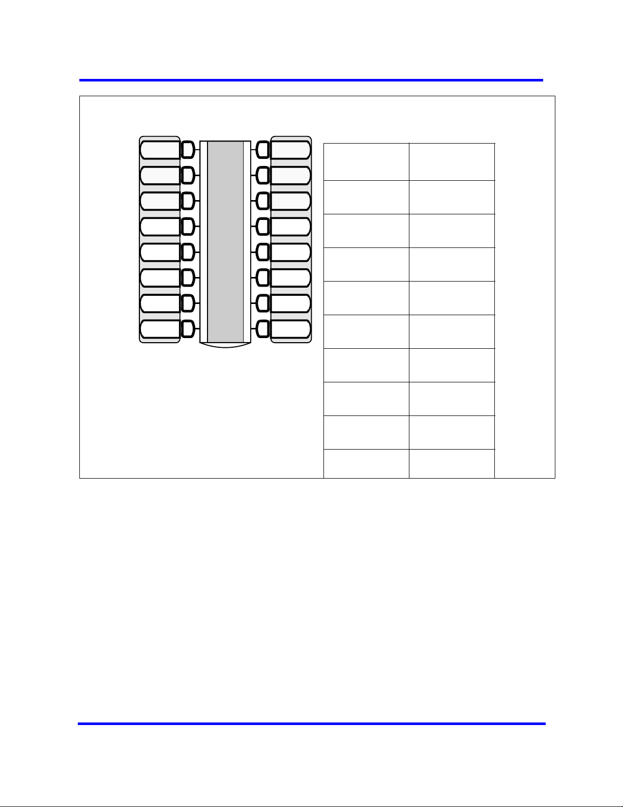
SWCA overview
Labelling your telephone keys provides identification about which code is
applied to which key. (See diagram below.)
Copyright © 2009 Nortel Networks
Nortel Business Communication Manager 5.0
Configuration — Devices
NN40170-500 02.04 Standard
August 2009
Page 30
30 Device configuration overview
Assigning SWCA keys
Line 1
Line 2
SWCA1
SWCA2
SWCA3
SWCA4
SWCA5
SWCA6
Intercom
Intercom
If possible, assign the same set of
buttons to the same SWCA user
codes for all telephones in the call
group.
You can use any name for the keys,
but a reference to the SWCA code
saved on the key is useful.
Indicate the label for your SWCA keys
Telephone key
#
SWCA code
FEATURE
*521
FEATURE
*522
FEATURE
*523
FEATURE
*524
FEATURE
*525
FEATURE
*526
FEATURE
*527
FEATURE
*528
FEATURE
*529
Use of Hold with SWCA keys
If a call does not automatically park on a SWCA key when you press HOLD, it
means the call is parked only on your telephone on the line on which the call
entered. To make the call available to the group, you must unhold the call
(press HOLD), then press a free SWCA key. The call is parked on that SWCA
key and the line on which the call entered becomes free.
Temporarily parked calls
someone picks up the call. In this case, if the person who answered the call
wants to repark the call, they must use one of the manual methods described
above to repark the call on a free SWCA key.
The system can be configured to retain the call on the same SWCA key for the
duration of the call, which is the period until someone hangs up, regardless of
how many times the call is answered and reparked.
Copyright © 2009 Nortel Networks
Nortel Business Communication Manager 5.0
Configuration — Devices
NN40170-500 02.04 Standard
August 2009
Page 31

Key availability and programming
If all your SWCA keys have assigned calls, and you receive another call, you
can:
If you assign a call to a code that does not have an appearance on your
telephone, use Page, Voice call, or Message to notify the group or another
person that there is a call waiting, and on which code it was parked.
SWCA-feature interaction
If you are not sure which call to retrieve, you can use one of the following
codes to find the longest parked call or the most recently parked call.
• FEATURE *537 retrieves the oldest SWCA call. The indicator on all
telephones in the group becomes solid, indicating an active call. These
codes only work for telephones that have SWCA keys defined, and the
system only searches across the range of codes that are assigned for that
telephone.
• FEATURE *538 retrieves the most recent SWCA call. The indicator on all
telephones in the group becomes solid, indicating an active call.
Timed out SWCA calls
If a call remains parked and unanswered on a SWCA key for a pre-set period
of time (the Call Park timeout timer), the call unparks from the SWCA key and
rings again at the telephone from which it was last parked.
Device configuration overview 31
Outbound calls
You also can park out-dialed calls on a SWCA key. If your system is set up to
automatically assign calls to a SWCA key, the call will assign to a key as soon
as it is answered. Otherwise, during your call, you can press a free SWCA key
or HOLD to park the call on a SWCA key. This makes the call available to other
users in the group and it frees up your intercom or line.
SWCA and auto hold
Your telephone must be set to have Full Auto-hold so that a call automatically
gets placed on Hold if you answer a second call. If your telephone does not
have Auto Hold on, use FEATURE 73 to change the setting.
SWCA and call transfers
If you transfer the call to a telephone that does not have the same SWCA keys
assigned, the call will disappear from the SWCA key on your telephone when
the call transfers. If the call needs to be reassigned to your group, the person
who answered the call enters a SWCA control code that is assigned to your
group, to return the call to a SWCA designation at your telephone.
SWCA and conference calls
A conference call cannot be parked on a SWCA key.
Copyright © 2009 Nortel Networks
Nortel Business Communication Manager 5.0
Configuration — Devices
NN40170-500 02.04 Standard
August 2009
Page 32

32 Device configuration overview
You cannot conference a call that is parked on a SWCA key until it is
unparked.
Set Template Programming
Element Manager administrators can use the Set Template Programming
feature to manage data retrieval, presentation, and data application for
multiple sets by propagating the information and modifications through the
template. You can combine a number of set parameter settings into a
template. You can then assign those parameters to appropriate sets on the
BCM. You can use the template import and export feature or the BCM Backup
and Restore feature to achieve template portability. From one system, you can
perform a backup and select the template components you want to transfer to
another system. You then perform a restore of that back up and select those
components on another system.
Set template administration
The set template feature provides the graphical user interface (GUI) for
creating, changing, and deleting a template. Use the template to quickly
assign the same parameter settings from one set to several sets at the same
time. The parameters that you can configure using a set template are
• Line Parameters
— Type of Prime Line
— Number of Intercom Buttons
— Line Pool Access
— Meet-Me Conference
• Set Capabilities
— DND on Busy
— Handsfree Activation Type
— Handsfree Answerback
— Pickup Group
— Page Permission
— Page Group
— Direct Dial Assignment
— Priority Call Setting
— Autohold for Incoming Page
— Auxiliary Ringer Setting
— Call Redirect Setting
Copyright © 2009 Nortel Networks
Nortel Business Communication Manager 5.0
Configuration — Devices
NN40170-500 02.04 Standard
August 2009
Page 33

— Redirect Ringing Setting
— Receive Short Tones
— Silent Monitor Supervisor
— ATA Setting
• Call Forward Settings
— Call Forward No Answer Delay
— Call Forward On Busy
— Hotline Number Access Settings
• User Preferences
— Set Model
— Dialling Options
— Language
— Contrast Level
—Ring Type
Device configuration overview 33
— Button Settings for Phone
— Keep DN Alive (IP Sets)
— Set Restrictions
• Voice Mailbox provisioning
Template-to-set assignment
Assign a set template to specific sets, or DNs, to propagate changes to those
sets through template updates. When you assign a template to a set, you
create an association between that template and that set. Changes to
provisioning data are automatically propagated to the set through the
template.
If you assign a set to a template, and you use set-based administration to
modify a supported parameter, the system automatically disassociates the
template from the set. You are notified of this disassociation through the
logging system. This is done to ensure that all sets assigned the same
template remain consistent in their configuration.
Copyright © 2009 Nortel Networks
Nortel Business Communication Manager 5.0
Configuration — Devices
NN40170-500 02.04 Standard
August 2009
Page 34

34 Device configuration overview
You can assign, unassign, and reassign sets through the Set Assignments
panel. When you assign, unassign, or reassign sets to a template, a colorcoded telephone icon appears beside the DN of the modified set. A green icon
indicates a newly assigned set. A yellow icon indicates a reassignment of a
set from one template to another. A red icon indicates an unassignment.
Template import and export capability
You can save a template to a file from one BCM and then import that template
to another BCM. This removes the need to recreate identical templates
manually on each BCM to be able to configure sets across all BCMs in the
network in the same way.
Templates are platform specifc, so the import-export capability is possible
from a BCM50 to a BCM50 or from a BCM450 to a BCM450, but not possible
from a BCM50 to a BCM450 or vice-versa.
Set template creation
You can create templates in three ways:
• as an original template
• from a set (DN)
Nortel Business Communication Manager 5.0
Copyright © 2009 Nortel Networks
Configuration — Devices
NN40170-500 02.04 Standard
August 2009
Page 35

• from an existing template, including the default DID or PBX templates
Set association
You can associate a set with a template. Administrators can modify a set
template using Element Manager. After you modify a set template on the BCM
5.0, the changed parameters are applied to every set to which the template
has been assigned.
Voice mailbox setup
You can create a voice mailbox for a set that is associated with a template to
edit certain mailbox parameters and propagate those changes to all sets
associated with the template. Not all mailbox parameters are available for you
to edit through the set template. You can edit the following parameters:
• Page type
• Page zone
• Page retries
• Page retry interval
• Display in directory
Device configuration overview 35
• Enable Message Waiting Indicator
• Class of Service
• Outdial type
• Outdial line
When you assign a template to a set and you select the Create Mailbox check
box, the system checks for an existing voice mailbox. If no mailbox exists, a
new one is created. If a mailbox exists, the system applies the values you
select in the Voice Mail tab to the mailbox. When you create a mailbox through
a template, the mailbox number becomes the same as the DN.
If, after creating a mailbox, you deselect the Create mailbox check box, the
system does not delete any mailboxes. The parameters no longer appear in
the Voice Mail tab, however, to delete a mailbox, you must use CallPilot
Manager. For details on how to delete a mailbox, see CallPilot Manager Setup
and Operation Guide (NN40170-300).
Set and line renumbering
Use the Element Manager to quickly renumber specific parameters in the sets
and lines configuration. The following list shows the parameters that you can
renumber using a template:
• DNs
• Public OLI
Copyright © 2009 Nortel Networks
Nortel Business Communication Manager 5.0
Configuration — Devices
NN40170-500 02.04 Standard
August 2009
Page 36

36 Device configuration overview
• Private OLI
• Target Line Assignments
• Public Received Digits
• Private Received Digits
You renumber parameters that are specific to lines or sets. Use the
renumbering function to renumber set and line parameters.
When you renumber DNs, all related parameters, such as the DN name, also
change incrementally. When you renumber DNs and the set has a voice
mailbox, you have an option to renumber the mailbox together with the DN. In
this case, the mailbox is deleted and a new one is created using the same
parameters that existed for the old mailbox, with the exception of the
extension. The extension field is set to the new DN created by renumbering
process.
Copyright © 2009 Nortel Networks
Nortel Business Communication Manager 5.0
Configuration — Devices
NN40170-500 02.04 Standard
August 2009
Page 37

System parameter configuration
The information in this section applies to both the BCM50 and the BCM450
platforms running BCM 5.0.
You can configure some basic system information for the Business
Communications Manager (BCM 5.0).
System parameter configuration navigation
• Accessing system identification (page 37)
• Setting date and time (page 38)
• Synchronize system with an NTP Server or trunk (page 39)
• Setting clock control to local system (page 40)
• System scheduled services (page 40)
Accessing system identification
You can access the system identification panel to see information about the
BCM system. The fields are read-only except for the Name.
Procedure steps
Step Action
1 Click Configuration > System > Identification.
2 In the System name field, type a unique name for the BCM.
Copyright © 2009 Nortel Networks
--End--
Nortel Business Communication Manager 5.0
Configuration — Devices
NN40170-500 02.04 Standard
August 2009
Page 38

38 System parameter configuration
Variable definitions
Variable Value
Model This is the system hardware release currently running on this
device. <read-only>
System name It is easier to manage a group of systems if each system is
provided with a unique name or identification number. The
system name must be a unique alphanumeric name that cannot
begin with a number or hyphen (-), and cannot end with hyphen
or period (.).
System software version The version of software running on the BCM Main Unit.<read-
only>
Country or region This setting defines internal system settings for default values,
available languages, and hardware and functional availability for
a specific country or region. <read-only>
Setting date and time
How you set the Date and Time feature for your system depends on whether
your system receives this information from a network server.
Step Action
1 Click Configuration > System > Date and Time.
2 Select the fields you want to modify.
--End--
Variable Definitions
Variable Value
Date and Time Source Set to NTP (Network Time Protocol) if the system uses a network
server to determine the correct time and date.
Set to Trunk to use time and date settings from a CO through an
analog or IDSN line.
Set to Manual if you want to be able to manually configure the
time and date for your system.
Default: Manual
Network Time Protocol Settings (Settings are active only if Clock Control Type is set to
Network Time Protocol.)
NTP server address The IP address of the server that controls the network time and
date.
Copyright © 2009 Nortel Networks
Nortel Business Communication Manager 5.0
Configuration — Devices
NN40170-500 02.04 Standard
August 2009
Page 39

System parameter configuration 39
Variable Value
Synch every (s) The number of seconds specified to elapse between contacts
with the NTP server.
1-XXXX: Number of seconds between contacts with the NTP
server.
NTP security mode Select whether the NTP security mode is secured or unsecured.
Raise alarm if clock
differs by at least (s)
NTP key ID ID for accessing the NTP.
NTP key string Control key corresponding to ID for accessing the NTP. <8
Current Date and Time
Date and time The current date and time.
Time zone The appropriate time zone for the location of this system. The
Daylight Savings Time The appropriate mode for the Time zone.
The number of discrepancy seconds specified that must occur
before the system notifies you of a time difference from the NTP
server, if the system automatically checks with the NTP server.
<1-65,535>
characters>
<specific date and time format>
Time zone must be set for software updates to be applied.
Selected: The system automatically updates the time twice a
year.
Cleared: The system never updates the time for Daylight
Savings Time.
<read-only>
Synchronize system with an NTP Server or trunk
If the system is to synchronize with an NTP Server or trunk, check the
following.
Step Action
1 Click Configuration > System > Date and Time.
2 In the Network Time Protocol Settings pane, click Modify.
3 Set Date and Time Source to NTP or Trunk.
4 In the NTP server address field enter the IP address of the NTP server.
5 Set the number of seconds between synchronizations in normal operations
6 In the bottom frame, ensure that the Time zone is correct for the location of
Copyright © 2009 Nortel Networks
(Synch Every).
the local system.
Nortel Business Communication Manager 5.0
Configuration — Devices
NN40170-500 02.04 Standard
August 2009
Page 40

40 System parameter configuration
7 If Trunk was selected in the Date and Time Source drop-down list, enter the
year in the Year field.
8 Click Ok.
Only time and date info are updated when NTP and Trunk settings
are selected. Year information is not updated. You also have full
control over time and date settings using telset admin even if NTP or
Trunk are selected. Any setting applied through telset admin are
over-written by the external source if NTP or Trunk are selected. Time
zones need to be set for software updates to be applied
Setting clock control to local system
If you want the clock to be controlled locally, follow this procedure.
Step Action
1 Ensure that Date and Time Source is set to Manual.
--End--
2 In the bottom frame, in the Date and time field, enter the month, day and
year, hours and minutes and time of day.
3 In the bottom frame in the Time zone field, select the Time zone the system
uses.
4 In the bottom frame, the Daylight Savings Time check box is selected or
cleared automatically, depending on the time zone selected.
System scheduled services
Use scheduled services to control how calls are answered in off-hours
(Ringing Groups), how calls are routed at various times of the day, and how
restrictions are applied on lines and telephones at specific times of the day.
Navigation System scheduled services
• Configuring schedule name and timers (page 40)
• Configuring scheduled service (page 42)
Configuring schedule name and timers
The tables on this panel allow you to change the names of the schedules, and
to determine when the schedules, which are set to automatically execute, are
deployed. Any changes to these settings affect all services that use
schedules.
--End--
Copyright © 2009 Nortel Networks
Nortel Business Communication Manager 5.0
Configuration — Devices
NN40170-500 02.04 Standard
August 2009
Page 41

System parameter configuration 41
Procedure steps
Step Action
1 Click Configuration > Telephony > Scheduled Services.
2 Select the fields you want to modify.
--End--
Variable Definitions
Variable Value
Schedules
Schedules Double-click the field, and enter a descriptive name for the
schedule. <alphanumeric>
Schedule Times
For each schedule, there are timers for the seven days of the week.
Day <seven days>
Start Time This is the time when the schedule starts, and any previously-
running schedules stop.
Use a 12-hour or 24-hour format. If the entry is less than 12:00,
the system prompts for a day period setting.
00:00 = schedule is off
start and stop are the same = schedule runs for 24 hours
start: 22:00/stop: 06:00 = schedule starts at midnight, runs until
6 a.m., then starts again at 10 p.m. (22:00).
Stop Time This is the time when the schedule stops
00:00 to 12:00 a.m.-p.m./24:00
Job aid: Schedule services - settings and Schedules panel
The Scheduled Services - Settings and Schedules panel has three distinct
areas for configuration.
The table in the top frame allows you to determine which schedules are active
for the system for routing, restriction, and ringing schedules.
The table in the top frame to the right sets the time periods within each
schedule for each day of the week.
The table in the bottom frame allows you to rename schedules.Schedules are
activated and deactivated through control telephones. For more information
see Configuring a control telephone (page 149). Restriction and Routing
Copyright © 2009 Nortel Networks
Nortel Business Communication Manager 5.0
Configuration — Devices
NN40170-500 02.04 Standard
August 2009
Page 42

42 System parameter configuration
services require a service control password before users are allowed to
change scheduling on a control telephone. The Service Control Password
field on this panel allows you to delete a current entry, and add a new
password. Make a note of the password; the panel displays only asterisks.
Configuring scheduled service
Configure the settings for the schedules that you are using for your system.
Procedure steps
Step Action
1 Click Configuration > Telephony > Scheduled Services.
2 Select the fields you want to modify.
Variable Definitions
Variable Value
--End--
Service Control
Password
Schedule These are the schedules that are available on the system.
Routing Svc Off prevents the service from being activated.
Restriction and Routing schedules require the user to enter a
password on the control telephone before scheduling can be
changed. If you forget the password, enter a new password.
<alphanumeric>
<read-only>
Manual allows you to turn the service on and off at any time from
a control telephone. This setting overrides any automaticallyrunning schedules.
Auto allows you to program a stop and start time for a service
under the Common Settings heading. These times are then
automatically executed when the service is active.
Default: Off
Copyright © 2009 Nortel Networks
Nortel Business Communication Manager 5.0
Configuration — Devices
NN40170-500 02.04 Standard
August 2009
Page 43

System parameter configuration 43
Variable Value
Overflow If all the lines used by a route are busy when a call is made, you
can program Routing service to overflow to the route used for
normal mode. If the call is routed to use the normal mode, the
telephone sounds a warning tone and displays the message
Expensive route. The caller then can release the call to avoid the
toll charges or can continue.
Tips: A schedule must be active for overflow routing to be in
effect. Overflow routing is not available in normal mode.
You must create an overflow route to be used with each routing
code. In this way, every route used with a scheduled mode that
has overflow service must have an alternate route in normal
service.
Default: Cleared
Ringing Svc Off prevents the service from being activated.
Manual allows you to turn the service on and off at any time from
a control telephone. This setting overrides any automaticallyrunning schedules.
Auto allows you to program a stop and start time for a service
under the Common Settings heading. These times are then
executed automatically when the service is active.
Default: Off
Trunk Answer Trunk answer allows you to answer, from any telephone, an
external call that is ringing at another telephone in your office, if
the Ringing Service is active on that line at the time of the call. If
the service is not active, you cannot answer the call.
Trunk answer is useful if the other telephones are not assigned
the same lines as the telephone you are using to answer the call.
Note: You can change the Trunk Answer setting only if Ringing
service is set to Manual or Auto.
Default: Selected
Copyright © 2009 Nortel Networks
Nortel Business Communication Manager 5.0
Configuration — Devices
NN40170-500 02.04 Standard
August 2009
Page 44

44 System parameter configuration
Variable Value
Extra dial set The Extra dial set attribute allows you to assign an additional
telephone to receive calls for each schedule.
Note: The extra dial set is activated during a schedule by
entering the Ringing service feature code from the assigned
direct dial telephone. This does not activate the Ringing service,
unless the direct dial telephone is also a control set.
Restriction Svc Off prevents the service from being activated.
Manual allows you to turn the service on and off at any time from
a control telephone. This setting overrides any automaticallyrunning schedules.
Auto allows you to program a stop and start time for a service
under the Common Settings heading. These times are then
executed automatically when the service is active.
Default: Off
Copyright © 2009 Nortel Networks
Nortel Business Communication Manager 5.0
Configuration — Devices
NN40170-500 02.04 Standard
August 2009
Page 45

Basic parameters for analog sets and devices configuration
The information in this section applies to both the BCM50 and the BCM450
platforms running BCM 5.0.
Determine the programming for individual telephones and devices attached to
analog station modules or to digital station modules through an analog
terminal adapter (ATA) module.
Analog sets can be configured using Set Templates. For more information
about Set Templates, see Set Template Programming (page 32).
Configuring basic parameters for analog sets and devices navigation
• Configuring analog telephones (page 46)
• Assigning a line to an analog telephone (page 47)
• Adding line assignments and line pools for analog telephones (page 48)
• Configuring set capabilities and user preferences for analog telephones
(page 49)
• Configuring telephone capabilities for analog telephones (page 49)
• Programming outgoing call restrictions for analog telephones (page 51)
• Setting restriction filters for analog telephones (page 51)
• Setting line/set restrictions for analog telephones (page 52)
• Assigning pause for external dialing for analog devices (page 52)
Prerequisites
The following programming must be completed prior to performing this
configuration:
• Numbering plan
• Lines programming
• Analog or digital module installation, configuration and wiring to the
devices (ATA module, if required).
Copyright © 2009 Nortel Networks
Nortel Business Communication Manager 5.0
Configuration — Devices
NN40170-500 02.04 Standard
August 2009
Page 46

46 Basic parameters for analog sets and devices configuration
Configuring analog telephones
Use the following steps to configure analog telephones.
Procedure steps
Step Action
1 Click Configuration > Telephony > Sets > Active Sets.
2 On each panel on the DNs list, add or modify settings to customize the
telephone operations.
--End--
Variable Definitions
Variable Value
Model Analog
Name Unique to each device or device loop
Appearance Type Ring only
Caller ID Set Select check box (connected to ASM8+, GASM, or GASI devices
for calls from GASM or target lines)
Intercom keys Two: not configurable
The following settings are the only capability settings that are valid for analog devices.
ATA answer timer Keep short for modems and fax machines
ATA tones check box
ATA use On site
Off site works for devices connected to ATA modules only
Msg indicate
ATA device modem/telephone
Disconnect supervision Select for auto-answer modems and fax machines
Do not select for telephones
Supported by ASM8+, GASM, and GASI devices
The following settings are common settings that are specific to analog telephones.
Handsfree/HF Answerback Do not select
Page settings Select check box
Can send pages but cannot receive pages
Receive short tones Select check box (analog telephones only)
Nortel Business Communication Manager 5.0
Copyright © 2009 Nortel Networks
Configuration — Devices
NN40170-500 02.04 Standard
August 2009
Page 47

Basic parameters for analog sets and devices configuration 47
Variable Value
Hotline
The following settings are not valid (N/V) or are limited on analog devices.
Keep DN Alive N/V
Silent monitor supervision Do not select
DND on Busy Do not select
Priority call Do not select
Auto hold Do not select
Allow Link Select check box (telephones only)
All other settings are variable, based on your system requirements.
Assigning a line to an analog telephone
Use the following steps to assign a line to an analog telephone.
Procedure steps
Step Action
1 Click Configuration > Telephony > Sets > Active Sets > Line Access.
2 Select the DN to which you want to add a line.
3 In the details for the DN section, select the field that you want to modify.
--End--
Variable Definitions
Variable Value
Name Enter a name that identifies the user or the location (maximum of
seven digits).
Port Enter the port number for the device.
Pub. OLI Enter or confirm the number that displays at the far end for calls
going out over the public network (only on digital and VoIP
trunks).OLI numbers can be bulk changed using the Renumber
button available under Configuration>Telephony>Sets>All
DNs.
Priv. OLI Enter or confirm the number that displays at the far end for calls
going over the private network. This number is usually the same
as the DN (only on digital and VoIP trunks). OLI numbers can be
bulk changed using the Renumber button available under
Configuration>Telephony>Sets>All DNs.
Copyright © 2009 Nortel Networks
Nortel Business Communication Manager 5.0
Configuration — Devices
NN40170-500 02.04 Standard
August 2009
Page 48

48 Basic parameters for analog sets and devices configuration
Variable Value
Fwd No Answer Enter the number of the device that receives calls when this
telephone does not answer. The device can be another
telephone or a voice mail service
Fwd Delay Confirm or change the number of rings you want to occur at the
telephone before a call is forwarded. (Default: 4).
Fwd Busy Enter the number of the device you want to receive calls when
this telephone is busy. This can be another telephone or a voice
mail service.
Fwd All Enter the number of the device where all calls to this telephone
are forwarded.
Adding line assignments and line pools for analog telephones
Use the following steps to assign lines and line pools.
Procedure steps
Step Action
1 Click Configuration > Telephony > Sets > Active Sets.
2 Select the Line Access tab.
3 Select the Line Assignment tab in the bottom panel.
4 Click Add to add line assignments for the telephone.
The Add Line Assignments box appears.
5 Enter the Line number.
6 Click Ok.
7 Configure the remaining fields.
Not all of these fields apply to all types of lines.
Appearance Type/Appearances (target lines)
Caller ID Set (target lines)
Vmsg Set
Priv. Received #
Pub. Received #
8 Click the Line Pool Access tab.
9 Use the Add button to add line pools for the telephone.
The Add Line Pool box appears.
10 Enter the Line Pool.
11 Click Ok.
12 Click the Answer DNs tab.
13 Click Add.
Copyright © 2009 Nortel Networks
The Add Answer DN box appears.
Nortel Business Communication Manager 5.0
Configuration — Devices
NN40170-500 02.04 Standard
August 2009
Page 49

Basic parameters for analog sets and devices configuration 49
14 Enter the Answer DN.
15 Click Ok.
If the telephone does not have any buttons with indicators available to
provide an Answer DN appearance, ensure that Appearance Type is set to
Ring only.
Answer DNs, which are assigned to buttons, can also be used to autodial
that telephone.
--End--
Configuring set capabilities and user preferences for analog telephones
Use the following steps to configure set capabilities and user preferences.
Procedure steps
Step Action
1 Click Configuration > Telephony > Sets > Active Sets > Capabilities and
Preferences tab.
2 Select the DN that you want to modify.
3 Type a name or location associated with the DN.
4 Prime Line: Enter the facility that you want the telephone to use if no line,
line access code, or routing code is dialed before an outgoing dial string.
5 Intercom Keys: Confirm or change how many intercom keys you want the
telephone to have. The default is 2.
Programming note: At least one intercom key must be defined to allow
internal calls. Two intercom keys are recommended for conference calling.
Model 7000 and 7100 telephones are automatically assigned two intercom
keys, so users can alternate between two active calls.
6 Control Set: If the telephone uses any schedules other than the Normal
schedule, ensure that a DN for a control set is entered.
7 First Display: Choose Name if you want the caller’s name to be the first
information displayed. Set this field to Number to display the caller’s
telephone number first, or to Line, to display the calling line number first.
8 Auto Called ID: Select the check box if you want the user to see the name
and number display of the telephone they call.
--End--
Configuring telephone capabilities for analog telephones
Use the following procedure to configure telephone capabilities.
Copyright © 2009 Nortel Networks
Nortel Business Communication Manager 5.0
Configuration — Devices
NN40170-500 02.04 Standard
August 2009
Page 50

50 Basic parameters for analog sets and devices configuration
Procedure steps
Step Action
1 Click Configuration > Telephony > Sets > Active Sets.
2 Select the Capabilities and Preferences tab.
3 In the bottom frame, on the Capabilities tab, confirm or change how the
telephone functions with system features.
--End--
Variable Definitions
Variable Value
Handsfree settings Handsfree: Select the setting that is appropriate for the type of
telephone.
HF answerback: Select the check box only if the telephone
allows handsfree, and is in an environment where speakers do
not cause disruption.
Page settings Page zone: If you have various areas that receive different page
announcements, place the telephone in the appropriate zone.
Paging: Select the check box if the telephone can send or
receive page messages.
Programming note: Telephones without speakers, such as
models 2001, 1110, 7000, and 7100, allow page messages to be
sent, but not to be received.
Interrupting calls DND on Busy: Select the check box if you want the caller to
receive a Do Not Disturb message when the telephone is busy.
Ensure this feature is selected, when the Fwd Busy field has a
value.
Priority call: Select the check box if you want the user to be able
to forward calls that alert at the telephone where the call was
forwarded, even when that telephone is busy.
Intrusion protection level: Select an intrusion level if you want the
user to be able to break into calls on other telephones. The
intrusion level must be the same or higher than the telephone
being interrupted.
Auto hold Select the check box if you want calls coming into the telephone
to be placed on hold automatically when the user answers
another call, or dials out while an incoming call is active.
Copyright © 2009 Nortel Networks
Nortel Business Communication Manager 5.0
Configuration — Devices
NN40170-500 02.04 Standard
August 2009
Page 51

Basic parameters for analog sets and devices configuration 51
Variable Value
Redirect settings Allow redirect: Select the check box if you want the user to be
able to redirect active lines to other telephones.
Redirect ring: Select the check box if you want calls coming into
a redirected line to give a short alert.
Receive short tones Do not select this for digital telephones.
Administrative capabilities Pickup group: If you want to allow this telephone to be answered
by other telephones in a defined group, choose the appropriate
group. Otherwise, leave the field blank.
Direct dial: Select the direct dial telephone assignment that you
want this telephone to be able to dial with one digit (direct dial
access code).
Silent monitor supervisor: Select this check box to enable the
telephone to monitor hunt group calls.
Programming outgoing call restrictions for analog telephones
Restriction filters determine what dialing strings are allowed or blocked from
the user. You can specify restriction filters specific to the telephone, as well as
filters that are specific to a line assigned to the telephone.
• restriction filters
• line restrictions
• CoS passwords
Procedure steps
Step Action
1 Click Configuration > Telephony > Sets > Active Sets > Restrictions tab.
2 Select the DN that you want to modify.
3Set Lock: Determine how much programming the user is able to perform at
their telephone. Choose from None, Partial or Full.
4 Allow last number: Select the check box if you want to allow redialing a
saved number.
5 Allow link: Select this check box only for analog telephones.
--End--
Setting restriction filters for analog telephones
Assign restriction filters for the schedules that will affect this telephone.
Copyright © 2009 Nortel Networks
Nortel Business Communication Manager 5.0
Configuration — Devices
NN40170-500 02.04 Standard
August 2009
Page 52

52 Basic parameters for analog sets and devices configuration
Procedure steps
Step Action
1 Click Configuration > Telephony > Sets > Active Sets > Restrictions tab.
2 Select the field you want to change.
3 Enter the restriction filter appropriate for the schedule. You will always need
a filter specified for the Normal schedule.
4 Repeat for each schedule.
--End--
Setting line/set restrictions for analog telephones
Assign restriction filters for the schedules that will affect the lines assigned to
this telephone.
Procedure steps
Step Action
1 Click Configuration > Telephony > Sets > Active Sets > Line/Set
Restrictions tab.
2 Select the line you want to modify.
3 Select the field you want to modify on that line.
4 Enter the restriction filter appropriate for the schedule. You always need a
filter specified for the Normal schedule.
5 Repeat for each line.
--End--
Assigning pause for external dialing for analog devices
The external Hotline feature provides automatic access to a line when an
analog device goes off-hook.
Procedure steps
Step Action
1 Click Configuration > Telephony > Sets > Active Sets.
2 Select the Capabilities and Preferences tab.
Copyright © 2009 Nortel Networks
Nortel Business Communication Manager 5.0
Configuration — Devices
NN40170-500 02.04 Standard
August 2009
Page 53

Basic parameters for analog sets and devices configuration 53
3 In the bottom panel, select the Preferences tab.
4 In the Hotline type drop-down list, select External.
5 Set the Facility field to Use prime line.
6 Click “P” from the drop-down keypad in the External number field. This
feature code inserts a 1.5-second pause before the device dials out.
7 Click Ok.
--End--
Copyright © 2009 Nortel Networks
Nortel Business Communication Manager 5.0
Configuration — Devices
NN40170-500 02.04 Standard
August 2009
Page 54

54 Basic parameters for analog sets and devices configuration
Copyright © 2009 Nortel Networks
Nortel Business Communication Manager 5.0
Configuration — Devices
NN40170-500 02.04 Standard
August 2009
Page 55

Basic parameters for digital sets configuration
The information in this section applies to both the BCM50 and the BCM450
platforms running BCM 5.0.
Determine the programming for individual telephones and devices attached
directly to digital media bay modules, or the fixed digital ports on the main
chassis. Digital sets can be configured using Set Templates. For more
information about Set Templates, see Set Template Programming (page 32).
Prerequisites
• Modules are installed, and you understand which ports and DNs can be
assigned to your telephones.
• Lines and routes programming are created for dialing the local PSTN.
Target lines are created where required by the type of trunks you are
using. Note: The line must be configured as supervised/guarded.
• Appropriate restriction filters are created to allow or disallow out-dialed
calls.
• Telephony system features have been programmed, and you understand
which features are not available to all users.
Configuring basic parameters for digital sets navigation
• Configuring digital telephones using the DN panels (page 56)
• Assigning a line to a digital telephone (page 56)
• Adding line assignments and line pools to digital telephones (page 58)
• Configuring set capabilities and preferences for digital sets (page 59)
• Configuring digital telephone capabilities (page 61)
• Configuring preferences for a digital telephone (page 63)
• Programming digital telephone memory buttons (page 63)
• Programming user speed dials for digital telephones (page 65)
• Programming outgoing call restrictions for digital telephones (page 65)
Copyright © 2009 Nortel Networks
Nortel Business Communication Manager 5.0
Configuration — Devices
NN40170-500 02.04 Standard
August 2009
Page 56

56 Basic parameters for digital sets configuration
• Setting restriction filters for digital telephones (page 66)
• Setting line/set restrictions for digital telephones (page 66)
Configuring digital telephones using the DN panels
The DN record defines the specific function of each telephone within the
system. Perform the following steps to customize the DN operations.
Procedure steps
Step Action
1 Click Configuration > Telephony > Sets > All DNs.
2 On each panel on the DNs list, add or modify settings to customize the
telephone operations.
Assigning a line to a digital telephone
On each panel on the DNs list, add or modify settings to customize the
telephone operations.
--End--
Procedure steps
Step Action
1 Click Configuration > Telephony > Sets > Active Sets > Line Access.
2 Select the line listing the appropriate DN for the telephone.
3 Select the field that you want to modify.
--End--
Variable Definitions
Variable Value
Name Enter a name that identifies the user or the location (maximum of
seven digits).
Port Enter the port number for the device.
Pub. OLI Enter or confirm the number that displays at the far end for calls
going out over the public network (only on digital and VoIP
trunks). OLI numbers can be bulk changed using the Renumber
button available under Configuration>Telephony>Sets>All
DNs.
Copyright © 2009 Nortel Networks
Nortel Business Communication Manager 5.0
Configuration — Devices
NN40170-500 02.04 Standard
August 2009
Page 57

Basic parameters for digital sets configuration 57
Variable Value
Priv. OLI Enter or confirm the number that displays at the far end for calls
going over the private network. This number is usually the same
as the DN (only on digital and VoIP trunks). OLI numbers can be
bulk changed using the Renumber button available under
Configuration>Telephony>Sets>All DNs.
Fwd No Answer Enter the number of the device that receives calls when this
telephone does not answer. The device can be another
telephone or a voice mail service
Fwd Delay Confirm or change the number of rings you want to occur at the
telephone before a call is forwarded. (Default: 4).
Fwd Busy Enter the number of the device you want to receive calls when
this telephone is busy. This can be another telephone or a voice
mail service.
Fwd All Enter the number of the device where all calls to this telephone
are forwarded.
Job aid: Notes about assigning lines to telephones
Nortel recommends a maximum of four line buttons per telephone. You can
program more than four line buttons on a telephone by programming less than
four on other sets. For example, you might program 20 line buttons on a
receptionist telephone equipped as a CAP station, and only two lines on all
other telephones.
For BCM450, you can program a maximum of 93 telephones with a line
appearance for a specific line, including VoIP and target lines. Above this
maximum, you can configure more than one appearance per telephone of a
target line.
Note: This facility is not available in BCM50.
Do not assign auto-answer loop start trunks, auto-answer T1 E&M trunks, and
T1 DID trunks to telephones. These trunks are used to monitor incoming call
usage, or to place outgoing calls (auto-answer loop start and T1 E&M trunks).
A line that is configured as private cannot be assigned to another telephone.
Each line assigned to a telephone must appear to a button with an indicator.
The maximum number of available buttons is 8 for the 7208 digital telephones,
10 for the model 7310, 10 for 7316 digital telephones, 16 for the 7316E digital
telephone, and 24 for the model 7324 digital telephones. You need at least two
intercom buttons to use the conference feature.
Copyright © 2009 Nortel Networks
Nortel Business Communication Manager 5.0
Configuration — Devices
NN40170-500 02.04 Standard
August 2009
Page 58

58 Basic parameters for digital sets configuration
In addition to lines, buttons have other uses, for example, intercom or
handsfree operation. Line programming does not overwrite assigned
Intercom, Answer DN, Handsfree, or Hunt group buttons. However, intercom
buttons overwrite anything.
Answer DNs also overwrite line programming, but not Intercom buttons.
Answer DN buttons appear above Intercom buttons; if an Intercom button is
added after Answer DN buttons are assigned, the Intercom button pushes the
Answer DNs up. The top Answer DN overwrites whatever is above it.
If you set a line to Ring only, incoming calls appear on an intercom button.The
7000, 7100 digital telephones, are exceptions, they have no line buttons;
therefore, you can assign any number of lines, but only two lines can be
answered at any one time. Assign the lines on these telephones to ring;
otherwise, you cannot detect incoming calls on the lines.
An enhanced central answering position (eCAP), with one or more modules,
provides extra line button support, if the number of lines to assign exceeds the
number of available buttons with indicators. The remaining lines assign to
buttons on the module. The eKIM also supports hunt group designators, and
multiple appearances of the same target line, which flow to the module if there
are no available buttons with indicators on the 7316E digital phone.
Attention: If you do a Backup/Cold Start/Restore sequence on your BCM
5.0, button programming on an enhanced CAP (eCAP) module is lost, and
the lines assigned to those buttons are assigned to the buttons on the
telephone. These assignments displace any programming on the telephone
buttons, except Answer DN buttons, intercom buttons, handsfree buttons, or
Hunt group appearances. In the case where there are more reassigned lines
than buttons, the system still assigns the lines to the telephone, and the
telephone rings when a call comes in on that line (given that Appr&Ring is
configured on the line). To resolve this situation, access the DN records for
the telephone and the CAP/KIM button programming. Enter the required
programming.
By using FEATURE *81 at the telephone, lines can be moved to other buttons
on the telephone, except intercom, Answer DN, or handsfree positions, or the
lines can be moved to buttons on the modules on an eCAP. On telephones,
the feature or line, assigned to the button where the line is moved, moves to
the original line button position. On eCAP modules, moved lines overwrite
feature programming.
Adding line assignments and line pools to digital telephones
Use the following steps to assign lines and line pools.
Copyright © 2009 Nortel Networks
Nortel Business Communication Manager 5.0
Configuration — Devices
NN40170-500 02.04 Standard
August 2009
Page 59

Basic parameters for digital sets configuration 59
Procedure steps
Step Action
1 Click Configuration > Telephony > Sets > Active Sets.
2 Select the Line Access tab.
3 Select the Line Assignment tab in the bottom panel.
4 Click Add to add line assignments for the telephone.
The Add Line Assignments box appears.
5 Enter the Line number.
6 Click Ok.
7 Configure the remaining fields: Appearance Type/Appearances (target
lines), Caller ID Set (target lines), Vmsg Set, Priv. Received #, Pub.
Received #
Attention: Not all of these fields apply to all types of lines.
8 Click the Line Pool Access tab.
9 Use the Add button to add line pools for the telephone.
The Add Line Pool box appears.
10 Enter the Line Pool.
11 Click Ok.
12 Click the Answer DNs tab.
13 Click Add.
The Add Answer DN box appears.
14 Enter the Answer DN.
15 Click Ok.
Attention: If the telephone does not have any buttons with indicators available to
provide an Answer DN appearance, ensure that Appearance Type is set to Ring only.
Answer DNs, which are assigned to buttons, can also be used to autodial that
telephone.
--End--
Configuring set capabilities and preferences for digital sets
Use the following steps to configure set capabilities and user preferences.
Copyright © 2009 Nortel Networks
Nortel Business Communication Manager 5.0
Configuration — Devices
NN40170-500 02.04 Standard
August 2009
Page 60

60 Basic parameters for digital sets configuration
Procedure steps
Step Action
1 Click Configuration > Telephony > Sets > Active Sets > Capabilities and
Preferences tab.
2 Select the DN that you want to modify.
3 Type a name or location associated with the DN.
4 Prime Line: Enter the facility that you want the telephone to use if no line,
line access code, or routing code is dialed before an outgoing dial string.
5 Intercom Keys: Confirm or change how many intercom keys you want the
telephone to have. The default is 2.
Programming note: At least one intercom key must be defined to allow
internal calls. Two intercom keys are recommended for conference calling.
Model 7000 and 7100 telephones are automatically assigned two intercom
keys, so users can alternate between two active calls.
6 Control Set: If the telephone uses any schedules other than the Normal
schedule, ensure that a DN for a control set is entered.
7 First Display: Choose Name if you want the caller’s name to be the first
information displayed. Set this field to Number to display the caller’s
telephone number first, or to Line, to display the calling line number first.
8 Auto Called ID: Select the check box if you want the user to see the name
and number display of the telephone they call.
--End--
Job aid: Assigning intercom (I/C) buttons (keys)
The Intercom keys attribute assigns the number of intercom buttons on a
telephone. Intercom buttons provide access to a maximum of eight internal or
external lines and line pools. The user presses the intercom key to answer
internal calls, or to select a line or line pool to place a call. Lines configured for
Ring only also appear on intercom buttons.
If you assign a prime line to an intercom key, you are immediately connected
to a line when you press the button or lift the handset. A line indicator appears
beside the intercom button.
When you assign an intercom button during programming, the assignment
automatically appears on the telephone. Assignment starts at the lower-right
button, or one button above if the handsfree feature is available. Any feature
or line programming that existed previously on that button is overwritten,
except for Answer DNs that are pushed up one button.
Copyright © 2009 Nortel Networks
Nortel Business Communication Manager 5.0
Configuration — Devices
NN40170-500 02.04 Standard
August 2009
Page 61

Basic parameters for digital sets configuration 61
A telephone requires two intercom buttons to establish a conference call with
two other BCM telephones.
You require only one intercom button if the button is used to place and receive
internal calls, and to access line pools.
You require two intercom buttons for a telephone with several lines assigned
to Ring only.
Model 2001, 1110, 7000, and 7100 telephones and analog telephones are
automatically assigned two intercom buttons. This allows users to toggle
between two active calls using the Hold button.
Configuring digital telephone capabilities
Use the following procedure to configure telephone capabilities.
Procedure steps
Step Action
1 Click Configuration > Telephony > Sets > Active Sets > Capabilities and
Preferences tab.
2 In the bottom frame, on the Capabilities tab, confirm or change how the
telephone functions with system features.
--End--
Variable Definitions
Variable Value
Handsfree settings Handsfree: Select the setting that is appropriate for the type of
telephone.
HF answerback: Select the check box only if the telephone
allows handsfree, and is in an environment where speakers do
not cause disruption.
Page settings Page zone: If you have various areas that receive different page
announcements, place the telephone in the appropriate zone.
Paging: Select the check box if the telephone can send or
receive page messages.
Programming note: Telephones without speakers, such as
models 2001, 1110, 7000, and 7100, allow page messages to be
sent, but not to be received.
Copyright © 2009 Nortel Networks
Nortel Business Communication Manager 5.0
Configuration — Devices
NN40170-500 02.04 Standard
August 2009
Page 62

62 Basic parameters for digital sets configuration
Variable Value
Interrupting calls DND on Busy: Select the check box if you want the caller to
receive a Do Not Disturb message when the telephone is busy.
Ensure this feature is selected, when the Fwd Busy field has a
value.
Priority call: Select the check box if you want the user to be able
to forward calls that alert at the telephone where the call was
forwarded, even when that telephone is busy.
Intrusion protection level: Select an intrusion level if you want the
user to be able to break into calls on other telephones. The
intrusion level must be the same or higher than the telephone
being interrupted.
Auto hold Select the check box if you want calls coming into the telephone
to be placed on hold automatically when the user answers
another call, or dials out while an incoming call is active.
Redirect settings Allow redirect: Select the check box if you want the user to be
able to redirect active lines to other telephones.
Redirect ring: Select the check box if you want calls coming into
a redirected line to give a short alert.
Receive short tones Do not select this for digital telephones.
Administrative capabilities Pickup group: If you want to allow this telephone to be answered
by other telephones in a defined group, choose the appropriate
group. Otherwise, leave the field blank.
Direct dial: Select the direct dial telephone assignment that you
want this telephone to be able to dial with one digit (direct dial
access code).
Silent monitor supervisor: Select this check box to enable the
telephone to monitor hunt group calls.
Job aid: Line redirection notes
This feature enables you to send your external calls to a telephone outside the
office. You can decide to redirect all, or just some, of your external lines.
You can redirect only lines that appear as line buttons on your telephone.
Since 2001, 1110, 7000, and 7100 telephones do not have line buttons, they
do not support line redirection. Also, line redirection is not supported on
telephones connected to an ATA2 or ASM/GASM (analog station modules).
You can answer the telephone if it rings while you are programming line
redirection. However, call handling features are not available until the
programming wait period times out. If you need to use a feature to process the
call, quit line redirection programming by pressing FEATURE. If you press
RELEASE, the call is disconnected.
Copyright © 2009 Nortel Networks
Nortel Business Communication Manager 5.0
Configuration — Devices
NN40170-500 02.04 Standard
August 2009
Page 63

Basic parameters for digital sets configuration 63
In some conditions, callers can experience lower volume levels when you
redirect calls to an external location.
Attention: Be careful about redirection loops. For example, if you redirect
your lines to your branch office, and your branch office redirects its lines to
you, you can create a redirection loop. If these calls are long distance,
significant toll charges can result.
Attention: While programming Line Redirection, there is no indication of
calls to that telephone, except a call that rings the telephone.
Configuring preferences for a digital telephone
Use this panel to specify operational attributes. These attributes can also be
set at the telephone. Settings at the telephone override Element Manager
settings.
Procedure steps
Step Action
1 Click Configuration > Telephony > Sets > Active Sets > Capabilities and
preferences tab.
2 Click the Preferences tab in the bottom panel.
3 Call log options: Determine when calls are logged.
4 Dialing options: Determine how the user dials numbers.
Programming note: Some telephones do not allow all dialing options.
5 Contrast: Adjust the contrast level of the display.
6 Ring type: If you want incoming calls to produce a specific type of ring (for
example, to differentiate between two telephones that are in close
proximity), select one of the four ring types. If you select None, the default
ring is used.
--End--
Programming digital telephone memory buttons
Use this panel to assign features to available buttons on the telephone.
Procedure steps
Step Action
Copyright © 2009 Nortel Networks
Nortel Business Communication Manager 5.0
Configuration — Devices
NN40170-500 02.04 Standard
August 2009
Page 64

64 Basic parameters for digital sets configuration
1 Click Configuration > Telephony > Sets > Active Sets > Capabilities and
Preferences tab.
2 Select the DN of the telephone to program.
3 Click the Button Programming tab in the bottom panel.
4 The model shown in the model field determines the number of available
buttons.
Programming note: Assigned lines, answer DNs, hunt group designators,
and intercom keys cannot be overridden using this template.
5 Select the field beside the button you want to configure or change.
A Modify box appears.
6 Select the feature, internal or external autodial you want to assign.
7 Select from a list of available values to choose from.
8 Click Ok.
--End--
Job aid: Notes about button programming
• The number of available button positions depends on the model of
telephone that you are programming.
• New button programming overwrites memory button programming
performed at the telephone. Conversely, changes to memory button
programming, performed at the telephone, overwrites memory keys
programmed under Button programming or CAP/KIM button
programming. The panels reflect changes made at the telephone.
• The 7316 telephone has disjointed button numbering; it is because
patterned after the legacy 7310, but has fewer buttons than the 7310.
However, Button programming shows the 7310 button array. Refer to the
default button programming section to ensure that you program the correct
button numbers.
Button labeling: T-series telephones have a paper strip of labels that can be
customized and printed using the Desktop Assistant Pro, or the Desktop
Assistant Administrator Pro (AE) application. The AE version is located under
the administrator applications heading on the Element Manager web page.
The Desktop Assistant Pro is located under the User Applications heading on
the Element Manager web page. Desktop Assistant Pro requires a LAN CTE
keycode before it can be used. See the Keycode Install Guide (NN40010-301)
for more information on keycodes.
Copyright © 2009 Nortel Networks
Nortel Business Communication Manager 5.0
Configuration — Devices
NN40170-500 02.04 Standard
August 2009
Page 65

Basic parameters for digital sets configuration 65
Programming user speed dials for digital telephones
Use this tab to assign telephone numbers to speed dial codes. These codes
are available to all telephones in the system. The number of available codes
is determined under system feature programming.
Procedure steps
Step Action
1 Click Configuration > Telephony > Sets > Active Sets > Capabilities and
Preferences tab.
2 Select the DN of the telephone to program.
3 Click the User speed dial tab in the bottom panel.
4 Click Add.
The Add User Speed Dial box appears.
5 Enter the Speed Dial Number.
6 Click Ok.
7 Click on the External Number field and enter the external number to dial.
--End--
Programming outgoing call restrictions for digital telephones
Restriction filters determine what dialing strings are allowed or blocked from
the user. You can specify restriction filters specific to the telephone, as well as
filters that are specific to a line assigned to the telephone.
• restriction filters
• line restrictions
• CoS passwords
Procedure steps
Step Action
1 Click Configuration > Telephony > Sets > Active Sets > Restrictions tab.
2 Select the DN that you want to modify.
3Set Lock: Determine how much programming the user is able to perform at
their telephone. Choose from None, Partial or Full.
4 Allow last number: Select the check box if you want to allow redialing a
saved number.
5 Allow link: Select this check box only for analog telephones.
Copyright © 2009 Nortel Networks
Nortel Business Communication Manager 5.0
Configuration — Devices
NN40170-500 02.04 Standard
August 2009
Page 66

66 Basic parameters for digital sets configuration
Setting restriction filters for digital telephones
Assign restriction filters for the schedules that will affect this telephone.
Procedure steps
Step Action
1 Click Configuration > Telephony > Sets > Active Sets > Restrictions tab.
2 Select the field you want to change.
3 Enter the restriction filter appropriate for the schedule. You will always need
a filter specified for the Normal schedule.
4 Repeat for each schedule.
--End--
--End--
Setting line/set restrictions for digital telephones
Assign restriction filters for the schedules that will affect the lines assigned to
this telephone.
Procedure steps
Step Action
1 Click Configuration > Telephony > Sets > Active Sets > Line/Set
Restrictions tab.
2 Select the line you want to modify.
3 Select the field you want to modify on that line.
4 Enter the restriction filter appropriate for the schedule. You always need a
filter specified for the Normal schedule.
5 Repeat for each line.
--End--
Copyright © 2009 Nortel Networks
Nortel Business Communication Manager 5.0
Configuration — Devices
NN40170-500 02.04 Standard
August 2009
Page 67

IP phone configuration
The information in this section applies to both the BCM50 and the BCM450
platforms running BCM 5.0.
IP telephones have a very similar DN configuration to digital telephones.
There are several models of i-series telephones, and each telephone has a
different number of programmable buttons. See the Nortel i-series telephone
user cards for details.
IP phones can be configured using Set Templates. For more information about
Set Templates, see Set Template Programming (page 32).
Prerequisites
The following programming must be completed prior to performing this
configuration:
• Numbering plan
• Lines programming
• Telephony system feature programming
• IP telephony network setup
Attention: IP sets that do not have integrated switches must be connected
to the LAN through an Ethernet switch.
IP phone configuration navigation
• Configuring IP telephones (page 68)
• Assigning a line to an IP telephone (page 68)
• Adding line assignments and line pools to IP telephones (page 69)
• Configuring set capabilities and preferences for IP sets (page 70)
• Configuring IP telephone capabilities (page 71)
• Configuring preferences for an IP telephone (page 72)
Copyright © 2009 Nortel Networks
Nortel Business Communication Manager 5.0
Configuration — Devices
NN40170-500 02.04 Standard
August 2009
Page 68

68 IP phone configuration
Configuring IP telephones
Use the following steps to configure IP telephones.
Procedure steps
Step Action
1 Click Configuration > Telephony > Sets > All DNs.
2 On each panel on the DNs list, add or modify settings to customize the
telephone operations.
--End--
Variable Definitions
Variable Value
Model 2004, 2002, 2001, 2007, 2033, 1110, 1120E, 1140E, 2050,
2210, 2211, 2212, 1210, 1220, 1230, 6120, 6140
Name Unique to each handset
Line appearances Ring only (if not assigned to a button)
Caller ID set Selected (connected to target lines)
Answer DNs Ring only (if not assigned to a button)
Intercom keys At least one
Handsfree Auto
Dialing Options Auto
All other settings are variable, based on your system requirements.
Assigning a line to an IP telephone
Use the following steps to assign a line to an IP telephone.
Procedure steps
Step Action
1 Click Configuration > Telephony > Sets > Active Sets > Line Access.
2 Select the line listing the appropriate DN for the telephone.
3 Select the field that you want to modify.
Copyright © 2009 Nortel Networks
--End--
Nortel Business Communication Manager 5.0
Configuration — Devices
NN40170-500 02.04 Standard
August 2009
Page 69

IP phone configuration 69
Variable Definitions
Variable Value
Name Enter a name that identifies the user or the location (maximum of
seven digits).
Port Enter the port number for the device.
Pub. OLI Enter or confirm the number that displays at the far end for calls
going out over the public network (only on digital and VoIP
trunks). OLI numbers can be bulk changed using the Renumber
button available under Configuration>Telephony>Sets>All
DNs.
Priv. OLI Enter or confirm the number that displays at the far end for calls
going over the private network. This number is usually the same
as the DN (only on digital and VoIP trunks). OLI numbers can be
bulk changed using the Renumber button available under
Configuration>Telephony>Sets>All DNs.
Fwd No Answer Enter the number of the device that receives calls when this
telephone does not answer. The device can be another
telephone or a voice mail service
Fwd Delay Confirm or change the number of rings you want to occur at the
telephone before a call is forwarded. (Default: 4).
Fwd Busy Enter the number of the device you want to receive calls when
this telephone is busy. This can be another telephone or a voice
mail service.
Fwd All Enter the number of the device where all calls to this telephone
are forwarded.
Adding line assignments and line pools to IP telephones
Use the following steps to assign lines and line pools.
Procedure steps
Step Action
1 Click Configuration > Telephony > Sets > Active Sets.
2 Select the Line Access tab.
3 Select the Line Assignment tab in the bottom panel.
4 Click Add to add line assignments for the telephone.
The Add Line Assignments box appears.
5 Enter the Line number.
6 Click Ok.
7 Configure the remaining fields.
Copyright © 2009 Nortel Networks
Not all of these fields apply to all types of lines.
Nortel Business Communication Manager 5.0
Configuration — Devices
NN40170-500 02.04 Standard
August 2009
Page 70

70 IP phone configuration
8 Click the Line Pool Access tab.
9 Use the Add button to add line pools for the telephone.
10 Enter the Line Pool.
11 Click Ok.
12 Click the Answer DNs tab.
13 Click Add.
14 Enter the Answer DN.
15 Click Ok.
Attention: Programming note: If the telephone does not have any buttons with
indicators available to provide an Answer DN appearance, ensure that Appearance
Type is set to Ring only.
Answer DNs, which are assigned to buttons, can also be used to autodial that
telephone.
Appearance Type/Appearances (target lines)
Caller ID Set (target lines)
Vmsg Set
Priv. Received #
Pub. Received #
The Add Line Pool box appears.
The Add Answer DN box appears.
--End--
Configuring set capabilities and preferences for IP sets
Use the following steps to configure set capabilities and user preferences.
Procedure steps
Step Action
1 Click Configuration > Telephony > Sets > Active Sets > Capabilities and
Preferences tab.
2 Select the DN that you want to modify.
3 Type a name or location associated with the DN.
4 Prime Line: Enter the facility that you want the telephone to use if no line,
line access code, or routing code is dialed before an outgoing dial string.
5 Intercom Keys: Confirm or change how many intercom keys you want the
telephone to have. The default is 2.
Copyright © 2009 Nortel Networks
Nortel Business Communication Manager 5.0
Configuration — Devices
NN40170-500 02.04 Standard
August 2009
Page 71

Programming note: At least one intercom key must be defined to allow
internal calls. Two intercom keys are recommended for conference calling.
6 Control Set: If the telephone uses any schedules other than the Normal
schedule, ensure that a DN for a control set is entered.
7 First Display: Choose Name if you want the caller’s name to be the first
information displayed. Set this field to Number to display the caller’s
telephone number first, or to Line, to display the calling line number first.
8 Auto Called ID: Select the check box if you want the user to see the name
and number display of the telephone they call.
Configuring IP telephone capabilities
Use the following procedure to configure telephone capabilities.
Procedure steps
Step Action
IP phone configuration 71
--End--
1 Click Configuration > Telephony > Sets > Active Sets > Capabilities and
Preferences tab.
2 In the bottom frame, on the Capabilities tab, confirm or change how the
telephone functions with system features.
--End--
Variable Definitions
Variable Value
Handsfree settings Handsfree: Select the setting that is appropriate for the type of
telephone.
HF answerback: Select the check box only if the telephone
allows handsfree, and is in an environment where speakers do
not cause disruption.
Page settings Page zone: If you have various areas that receive different page
announcements, place the telephone in the appropriate zone.
Paging: Select the check box if the telephone can send or
receive page messages.
Programming note: Telephones without speakers allow page
messages to be sent, but not to be received.
Copyright © 2009 Nortel Networks
Nortel Business Communication Manager 5.0
Configuration — Devices
NN40170-500 02.04 Standard
August 2009
Page 72

72 IP phone configuration
Variable Value
Interrupting calls DND on Busy: Select the check box if you want the caller to
receive a Do Not Disturb message when the telephone is busy.
Ensure this feature is selected, when the Fwd Busy field has a
value.
Priority call: Select the check box if you want the user to be able
to forward calls that alert at the telephone where the call was
forwarded, even when that telephone is busy.
Intrusion protection level: Select an intrusion level if you want the
user to be able to break into calls on other telephones. The
intrusion level must be the same or higher than the telephone
being interrupted.
Auto hold Select the check box if you want calls coming into the telephone
to be placed on hold automatically when the user answers
another call, or dials out while an incoming call is active.
Redirect settings Allow redirect: Select the check box if you want the user to be
able to redirect active lines to other telephones.
Redirect ring: Select the check box if you want calls coming into
a redirected line to give a short alert.
Receive short tones Do not select this for digital telephones.
Administrative capabilities Pickup group: If you want to allow this telephone to be answered
by other telephones in a defined group, choose the appropriate
group. Otherwise, leave the field blank.
Direct dial: Select the direct dial telephone assignment that you
want this telephone to be able to dial with one digit (direct dial
access code).
Silent monitor supervisor: Select this check box to enable the
telephone to monitor hunt group calls.
Configuring preferences for an IP telephone
Use this panel to specify operational attributes. These attributes can also be
set at the telephone. Settings at the telephone override Element Manager
settings.
Procedure steps
Step Action
1 Click Configuration > Telephony > Sets > Active Sets > Capabilities and
preferences tab.
2 Click the Preferences tab in the bottom panel.
3 Call log options: Determine when calls are logged.
Copyright © 2009 Nortel Networks
Nortel Business Communication Manager 5.0
Configuration — Devices
NN40170-500 02.04 Standard
August 2009
Page 73

IP phone configuration 73
4 Dialing options: Determine how the user dials numbers.
Programming note: Some telephones do not allow all dialing options.
5 Contrast: Adjust the contrast level of the display.
6 Ring type: If you want incoming calls to produce a specific type of ring (for
example, to differentiate between two telephones that are in close
proximity), select one of the four ring types. If you select None, the default
ring is used.
--End--
Copyright © 2009 Nortel Networks
Nortel Business Communication Manager 5.0
Configuration — Devices
NN40170-500 02.04 Standard
August 2009
Page 74

74 IP phone configuration
Copyright © 2009 Nortel Networks
Nortel Business Communication Manager 5.0
Configuration — Devices
NN40170-500 02.04 Standard
August 2009
Page 75

Telephone relocation
The information in this section applies to both the BCM50 and the BCM450
platforms running BCM 5.0.
You can physically move a telephone within the system so that the telephone
programming follows the telephone to the new location.
Navigation
• Digital telephone relocation (page 75)
• Keeping an IP telephone active (page 76)
• IP telephone relocation without changing the DN (page 76)
• IP telephone relocation with a changed DN (page 76)
Digital telephone relocation
To move a digital telephone you must first enable set relocation in Element
Manager.
Procedure steps
Step Action
1 In the Element Manager, go to Configuration > Telephony > Global
2 In the Feature Settings section, select the Set relocation check box.
3 Clear the Set relocation check box.
Copyright © 2009 Nortel Networks
Settings > Feature Settings.
Move the telephone by physically unplugging the telephone and plugging it
in again at another location.
It can take up to 45 seconds for the system to recognize the telephone.
--End--
Nortel Business Communication Manager 5.0
Configuration — Devices
NN40170-500 02.04 Standard
August 2009
Page 76

76 Telephone relocation
Keeping an IP telephone active
To keep an IP telephone active after it is disconnected, you must change a
setting in Element Manager.
Procedure steps
Step Action
1 In the Element Manager, go to Configuration > Telephony > Sets > Active
Sets.
2 Click the Capabilities and Preferences tab.
3 Click IP Terminal details.
4 Select the Keep DN alive check box.
Clear the Keep DN alive check box to allow the Direct Number (DN) record
to become inactive if the IP telephone is disconnected.
--End--
IP telephone relocation without changing the DN
To move an IP telephone without changing the DN, complete this procedure.
Procedure steps
Step Action
1 Disconnect the power from the IP telephone or three-port switch.
2 Disconnect the network connection.
3 At the new location, reconnect the network cable and the power connection.
4 If the new location is on a different subnet, you must make the appropriate
changes to the telephone IP addressing; however, do not change the S1 IP
or S2 IP address.
If your network is using partial DHCP, reconfiguration is not required at this
step.
5 Disconnect the power from the IP telephone or three-port switch.
--End--
IP telephone relocation with a changed DN
To move an IP telephone and change the DN, complete this procedure.
Copyright © 2009 Nortel Networks
Nortel Business Communication Manager 5.0
Configuration — Devices
NN40170-500 02.04 Standard
August 2009
Page 77

Telephone relocation 77
Procedure steps
Step Action
1 In the Element Manager, go to Configuration > Resources > Telephony
Resources.
2 On the Modules panel, select IP Sets.
3 Select the IP Terminal Details tab.
4 Select the DN that you want to deregister and click the Deregister button.
5 Disconnect the network connection and the power connection from the
telephone.
6 Reinstall the telephone at the new location, and reconfigure the telephone.
--End--
Copyright © 2009 Nortel Networks
Nortel Business Communication Manager 5.0
Configuration — Devices
NN40170-500 02.04 Standard
August 2009
Page 78

78 Telephone relocation
Copyright © 2009 Nortel Networks
Nortel Business Communication Manager 5.0
Configuration — Devices
NN40170-500 02.04 Standard
August 2009
Page 79

Central answering positions configuration
The information in this chapter applies to both the BCM50 and the BCM450
platforms running BCM 5.0.
Use the following tasks to configure central answering positions.
• Configuring CAP assignments (eCAPs) (page 79)
• Programming CAP/KIM buttons (page 80)
Configuring CAP assignments (eCAPs)
Use the CAP Assignment panel to designate 7316E+KIM units as eCAPs.
The following procedures describe how to use the fields on the CAP
Assignment panel.
Creating CAP stations
Use the following steps to create CAP stations.
Procedure steps
Step Action
1 Ensure that the telephone you want to use is configured and working on the
Attention: CAPs are available only on T7316E and M7324 digital sets and IP
Phone 2002, IP Phone 2004, and IP Phone 2007 sets.
2 Ensure that the KIM is installed on the appropriate telephone.
3 Refer to the installation user card that came with the module, if necessary.
4 Click on Configuration> Telephony> Global Settings> CAP
5 On the CAP Assignment table, click the line for the CAP you want to
Copyright © 2009 Nortel Networks
system.
Assignment.
configure as an eCAP.
Nortel Business Communication Manager 5.0
Configuration — Devices
NN40170-500 02.04 Standard
August 2009
Page 80

80 Central answering positions configuration
6 Select the Set DN field and type the DN for the telephone.
Programming CAP/KIM buttons
Use the following tasks to program CAP/KIM buttons.
• Programming module buttons (page 80)
Programming module buttons
Designating features or autodial numbers to the eKIM buttons can be
performed using the CAP/KIM Button Programming panel.
Procedure steps
Step Action
1 Click Configuration > Telephony > Sets > Active Sets.
2 Click the Capabilities and Preferences tab.
--End--
3 Select the DN for the CAP you want to configure.
4 In the lower panel, click the CAP/KIM Button Programming tab.
5 Select the line for the button number that you want to program.
6 Configure the feature or autodial on the button.
Procedure job aid
If the 7316E+KIM is configured as an eCAP, you can move lines onto the
module using FEATURE *81 on the telephone. You can also reassign Hunt
group designators to the KIM module by using the same feature. You can also
force lines onto the KIM by assigning more lines than the telephone buttons
can support. Extra lines automatically flow over to the module; however they
flow sequentially, starting on the top left at button 01. Also, they overwrite any
existing programming on the KIM, except existing line or hunt group (KIM)
assignments. Any of the buttons, without assigned lines, can be programmed
to dial internal or external numbers automatically, or to access a feature.
You cannot assign lines, target lines, or Hunt group indicators using button
programming. These must be performed through assigning lines to the
telephone, and, for hunt groups, configuring the telephone as a Hunt group
member. These lines are either moved to the modules, or overflow to the
module, if the telephone buttons cannot accommodate the new settings.
You cannot assign Hunt group DNs as an autodial button on the KIM
modules.
--End--
Copyright © 2009 Nortel Networks
Nortel Business Communication Manager 5.0
Configuration — Devices
NN40170-500 02.04 Standard
August 2009
Page 81

Hunt Group configuration
The information in this section applies to both the BCM50 and the BCM450
platforms running BCM 5.0.
The Hunt Groups panel allows you to set up call groups that are assigned a
common hunt group DN for incoming calls. The calls then are distributed to
the member telephones.
The following paths indicate where to configure hunt groups in Element
Manager and through Telset Administration:
• Element Manager: Configuration > Telephony > Hunt Groups
• Telset interface: **CONFIG > System prgrming > Hunt Groups.
Configuring Hunt Groups navigation
• Configuring Hunt Group general settings (page 81)
• Adding members to Hunt Groups (page 85)
• Deleting members from Hunt Groups (page 85)
• Changing order of members in Hunt Groups (page 86)
• Assigning lines to Hunt Groups (page 86)
• Deleting lines from Hunt Groups (page 87)
Configuring Hunt Group general settings
When you first set up a Hunt Group, you must identify how calls are handled
among the group.
Procedure steps
Step Action
1 Click Configuration > Telephony > Hunt Groups.
2 On the Hunt Groups table, select the hunt group you want to configure.
3 Fill out the columns across the table as required.
Nortel Business Communication Manager 5.0
Copyright © 2009 Nortel Networks
Configuration — Devices
NN40170-500 02.04 Standard
August 2009
Page 82

82 Hunt Group configuration
Attention: A linear hunt group DN assigned as the overflow telephone does not
support having the hunt group DN assigned as an Answer DN to any hunt group
member. If this occurs, the Answer DN does not ring at the hunt group telephone
when an overflow condition occurs. If the hunt group DN overflow telephone whether
assigned as an Answer DN to a non-group member, ensure that the Answer key for
your system is set to Extended. • Aux. Ringer: If an external ringer is installed,
indicate if the hunt group calls use it (select check box). • Distinct Ring: Define if
incoming hunt calls have a different ring than other calls received by the member.
Attention: If you assign a distinctive ring pattern for a Hunt Group, all calls offered
to telephones in the group use the assigned ring pattern. If no pattern is assigned,
or if the ring pattern is lower in status than the ring pattern of the line or the telephone
setting, the call uses the ring pattern with the highest status setting. Refer to the
sections that describe configuring Lines and DNs for information about assigning
distinctive ring patterns to lines and telephones.
--End--
Variable Definitions
Variable Value
HG This number identifies the hunt group to the system. This is also
the number assigned to the telephone, when you add the
telephone as a Hunt Group member. <01-30>
Name Enter a logical name that describes the group function. This
name also acts as calling line display for incoming calls.
<alphanumeric>
DN Add a DN. The DN number can be assigned to memory buttons
on telephones that are not part of the hunt group.
Copyright © 2009 Nortel Networks
Nortel Business Communication Manager 5.0
Configuration — Devices
NN40170-500 02.04 Standard
August 2009
Page 83

Hunt Group configuration 83
Variable Value
Mode Select how you want the line to present to the group.
Broadcast — simultaneously rings at each non-busy telephone
in the hunt group. All telephones receiving the call also display
the calling line identification from the line, if the telephone or line
is configured to offer that service. Any of the alerted telephones
can access the call. Only one call is presented to a hunt group at
a time. Other calls are queued until the first call is answered.
Then the next call rings on the remaining non-busy telephones.
This feature allows the call load to be continuously spread across
the entire member group.
Sequential — rings the first telephone in the hunt group list. If that
telephone is busy, the system continues down the hunt group
priority list until a non-busy telephone accepts the call. In this
case, all incoming calls are processed simultaneously, and are
delivered based on the priority list. With this feature, you can
program your top salesperson to be the first member of the Hunt
group to receive incoming calls.
Rotary — the call starts at the member telephone that appears
on the list after the telephone that answered the last call. If that
telephone is busy, the system proceeds down the priority list until
a non-busy telephone is reached. As many incoming calls can be
processed as there are available telephones to accept the call,
each call being presented in the described round-robin fashion.
Default: Broadcast
Hunt Delay If Mode is either Sequential or Rotary, Hunt Delay specifies how
much time to delay offering a Queued call to a member
telephone when that telephone becomes available. This is to
provide a break period for the users between calls. <1-10>
Default: 4 seconds
If Busy Select how you want the system to respond if all lines appear as
busy.
Busy tone: If all lines are busy, the user receives a busy tone.
Queue: If all lines are busy, the user hears ring back until an
agent is available.
Default: Busy tone
Copyright © 2009 Nortel Networks
Nortel Business Communication Manager 5.0
Configuration — Devices
NN40170-500 02.04 Standard
August 2009
Page 84

84 Hunt Group configuration
Variable Value
Queue Timeout Select the time for a call to remain in the Hunt Group. This value
defines the maximum time a call remains queued, and the
maximum time to offer a call before sending it to overflow if it is
not answered. If the queue times out before the call connects to
a member telephone, the call is terminated. If the call has been
offered to a member telephone, but is not answered when the
queue times out, the call is rerouted to the overflow DN.
15, 30, 45, 60, 120, or 180 (seconds)
Default: 60
Overflow This setting determines where unanswered calls are routed after
the Queue timeout occurs. If a call overflows back to the same
Hunt Group, the call goes to the bottom of the queue, and is
treated as a new call.
Answer DNs: A linear hunt group that has defined an overflow
telephone does not support having the overflow telephone
assigned as an Answer DN to any hunt group member. If this
occurs, the Answer DN does ring at the hunt group telephone
when an overflow condition occurs. Answer DNs are set up
under the Line Access heading for each DN.
<any system DN> (including a Hunt Group DN)
Default: Hunt Group DN
Aux. Ringer If selected, defines whether an auxiliary ringer (if installed) rings
for incoming calls to a hunt group. If cleared, the control of the
auxiliary ringer falls back to the control defined on a per
telephone or per line basis.
<check box>
Default: cleared
Distinct Ring Select a ring pattern for the hunt group.
None
Pattern 2, 3 or 4
Default: None
CAUTION If you assign a distinctive ring pattern for a Hunt
Group, all calls offered to telephones in the group will use the
assigned ring pattern. If no pattern is assigned, or if the ring
pattern is lower in status than the ring pattern of the line or the
telephone setting, the call uses the ring pattern with the highest
status setting. Refer to the sections that describe configuring
Lines and DNs for information about assigning distinctive ring
patterns to lines and telephones.
Copyright © 2009 Nortel Networks
Nortel Business Communication Manager 5.0
Configuration — Devices
NN40170-500 02.04 Standard
August 2009
Page 85

Adding members to Hunt Groups
The lower frame of the Hunt Group panel shows a list of DNs that are assigned
as members of the group, and the lines assigned to the hunt group.
Procedure steps
Step Action
1 Click on Configuration> Telephony> Hunt Groups.
2 On the Hunt Groups panel, select the group where you want to add
members.
3 In the Members subpanel in the lower frame, click Add.
4 Enter the DN for the telephone you want to add as a member.
5 Select an Appearance Type from the drop-down list.
Variable Definitions
Variable Value
Hunt Group configuration 85
--End--
Seq No This is the position of the telephone on the list. This is particularly
important for sequential calls, which start at the top of the list, and
move sequentially through the list. <Read only>
DN This is the DN of the telephone assigned to this hunt group.
Appearance Type Select the setting that suits the telephone and the environment.
Ring only: Telephone rings when a call comes in. (7000 and
7100 digital phones and telephones that have no available
programmable memory buttons with indicators) (model 7000
phones are supported in Europe only.)
Appr&Ring: Appears on a button with indicator, which flashes
when a call comes in, and it also rings.
Appr only: Appears on a button with indicator, which flashes
when a call comes in.
Deleting members from Hunt Groups
The lower frame of the Hunt Group panel shows a list of DNs that are assigned
as members of the group, and the lines assigned to the hunt group. You can
delete members from Hunt Groups.
Copyright © 2009 Nortel Networks
Nortel Business Communication Manager 5.0
Configuration — Devices
NN40170-500 02.04 Standard
August 2009
Page 86

86 Hunt Group configuration
Procedure steps
Step Action
1 Click on Configuration> Telephony> Hunt Groups.
2 On the Hunt Groups panel, select the group where you want to delete
members.
3 In the Members subpanel in the lower frame, click the DN row to be
removed.
4 Click Delete located under the Hunt Group Members subpanel.
A warning message appears.
5 Click Yes.
--End--
Changing order of members in Hunt Groups
Member order within a Hunt group is important. The member order
determines how a call routes through a Hunt group when the group is set to
either linear or rotary mode.
Procedure steps
Step Action
1 Click on Configuration> Telephony> Hunt Groups.
2 Click a member from the member list.
3 Click either the Up or the Down button. The system automatically reorders
the list.
Assigning lines to Hunt Groups
Multiple lines can be assigned to Hunt groups. However, a line can only exist
in one Hunt group. Programming note: Lines assigned to line buttons on
individual telephones take precedence over the lines assigned to Hunt group
buttons. Therefore, Nortel recommends that you do not assign lines to
individual telephone DN records for telephones that are part of a Hunt group.
--End--
Copyright © 2009 Nortel Networks
Nortel Business Communication Manager 5.0
Configuration — Devices
NN40170-500 02.04 Standard
August 2009
Page 87

Hunt Group configuration 87
Procedure steps
Step Action
1 Click on Configuration> Telephony> Hunt Groups.
2 On the Hunt Groups Members subpanel, select the hunt group where you
want to add lines.
3 In the Line Assignment subpanel in the lower frame, click Add.
4 Enter line numbers.
5 Click Ok.
--End--
Variable Definitions
Variable Value
Lines These are the lines/target lines that are assigned to the hunt
group. Ensure that they also are not assigned to any of the
member telephones.
Deleting lines from Hunt Groups
You can delete lines from Hunt Groups.
Procedure steps
Step Action
1 Click on Configuration> Telephony> Hunt Groups.
2 On the Hunt Groups Members subpanel, select the hunt group where you
want to delete lines.
3 In the Line Assignment subpanel in the lower frame, click Delete.
4 Click Yes.
--End--
Copyright © 2009 Nortel Networks
Nortel Business Communication Manager 5.0
Configuration — Devices
NN40170-500 02.04 Standard
August 2009
Page 88

88 Hunt Group configuration
Copyright © 2009 Nortel Networks
Nortel Business Communication Manager 5.0
Configuration — Devices
NN40170-500 02.04 Standard
August 2009
Page 89

External Hunt Group calls monitoring
The information in this section applies to both the BCM50 and the BCM450
platforms running BCM 5.0.
Use the Silent Monitor feature to monitor external hunt group calls within a
hunt group. Any two-line display telephone can be assigned as a supervisor
telephone to allow this feature.
• Using a silent monitor (page 89)
Using a silent monitor
Use the Silent Monitor feature to monitor external hunt group calls within a
hunt group. Any two-line display telephone can be assigned as a supervisor
telephone to allow this feature.
There are two places in the Element Manager where the feature configured:
Silent Monitor settings are configured on the Global Settings panel and
supervisor terminals are configured on the System DNs record.
On the Telset, there are three places to set up this feature:
• Terminals&Sets > select the DN > Capabilities > SM supervisor
• Passwords > SM passwd
• System prgrming > Featr settings > Silent monitor
Procedure steps
Step Action
1 Enter FEATURE *550.
2 Enter the Silent Monitor password. (Default: SILENT (745368))
3 Enter the DN for the Hunt group member you want to monitor.
4 Click Ok.
5 If there is an active external Hunt group call at that telephone, you are
Copyright © 2009 Nortel Networks
connected to the call. Once the session is established, a number of display
Nortel Business Communication Manager 5.0
Configuration — Devices
NN40170-500 02.04 Standard
August 2009
Page 90

90 External Hunt Group calls monitoring
key prompts allows the supervisor to silently monitor the call, or to break into
the call to provide support or instruction. Refer to “Common display
prompts” on page 235.
6 The display commands under the prompts allow you to use the display keys
to break into the call or exit and move to another DN
Attention: Some countries require that all monitoring is preceded by a tone before
monitoring begins.
Attention: If an agent is on conference call, you cannot monitor the hunt group call.
--End--
Copyright © 2009 Nortel Networks
Nortel Business Communication Manager 5.0
Configuration — Devices
NN40170-500 02.04 Standard
August 2009
Page 91

Hospitality system configuration
The information in this section applies to both the BCM50 and the BCM450
platforms running BCM 5.0.
Use the Hospitality panels to set up room telephones, and determine how they
function.
The following path indicates where to configure the hospitality settings in
Element Manager:
Element Manager: Configuration > Telephony > Hospitality
Complete the following procedures to configure your hospitality system.
• Setting up a hospitality system (page 91)
• Assigning a room to a set (page 92)
• Deleting a room assignment from a set (page 92)
• Setting call restrictions (by room) (page 93)
• Programming wake-up services (by room) (page 93)
Setting up a hospitality system
Use the following steps to set up a hospitality system.
Procedure steps
Step Action
1 Click Configuration > Telephony > Hospitality.
2 Determine a time each day when the telephones switch to indicate that the
rooms require servicing.
3 In the Services change time field, enter a 24:00 time designator for the
service time.
Nortel Business Communication Manager 5.0
Configuration — Devices
NN40170-500 02.04 Standard
Copyright © 2009 Nortel Networks
August 2009
Page 92

92 Hospitality system configuration
4 In the Requires Desk Password field, change the default password to a
one- to six-digit number. Keep this password in a secure place. Change the
password frequently.
5 If you want service personnel to enter a password when they dial in to
indicate a room has been serviced, enter a one- to six-digit password into
the Room condition password field. This field can be left blank also.
Assigning a room to a set
The Rooms context panel displays all telephones currently connected or
registered to the system
Procedure steps
Step Action
1 Click on Configuration> Telephony> Hospitality> Rooms tab.
2 Select the telephone DN you want to assign to a room.
--End--
3 Click in the Room Number column, and enter the room number.
4 Select or clear the Requires Desk Password check box, as required.
Attention: If you select the Requires Desk Password check box, ensure that a valid
desk password exists.
Deleting a room assignment from a set
Use the following step to delete a room assignment.
Procedure steps
Step Action
1 Click on Configuration> Telephony> Hospitality> Rooms tab.
2 Click the Room Number column
3 Delete the number.
--End--
Copyright © 2009 Nortel Networks
--End--
Nortel Business Communication Manager 5.0
Configuration — Devices
NN40170-500 02.04 Standard
August 2009
Page 93

Setting call restrictions (by room)
Use the following steps to set up call restrictions.
Procedure steps
Step Action
1 Determine what type of calls you want to allow from telephones using the
fields in the call restrictions box.
2 Click Configuration > Telephony > Call Security > Restriction Filters,
create four new restriction filters that reflect the levels of service you want to
allow. For instance, if a room is vacant, you can allow only emergency calls,
whereas, in a suite, you can allow a full range of call services.
3 Click the number of the Filter in the Filter table you wish to create. In the
Restrictions panel, click Add.
The Add Restriction dialog box appears.
4 Enter the desired number of digits. Click Ok.
5 Make a note of the restrictions that you create.
6 On the Hospitality - General panel, in the Call Restrictions subpanel, enter
the appropriate filter numbers beside each field.
Hospitality system configuration 93
--End--
Programming wake-up services (by room)
You can set up the room telephones to ring at preset times to act as an
automatic wake-up call.
Procedure steps
Step Action
1 Click on Configuration> Telephony> Hospitality.
2 In the Wake-Up Call Settings and Expired Wake-Up Call Settings boxes,
determine the following parameters.
3 In the Attempts field, select the number of times the alerter sounds, without
the telephone handset being lifted, before the alarm service automatically
cancels.
4 In the Retry interval field, select a time period (in minutes) that the system
waits between repeating the wake-up alerter.
5 In the Alarm duration (sec.) field, select the length of time the alert sounds
each time it repeats.
Copyright © 2009 Nortel Networks
Nortel Business Communication Manager 5.0
Configuration — Devices
NN40170-500 02.04 Standard
August 2009
Page 94

94 Hospitality system configuration
6 In the Notify DN field, enter the DN of an administration telephone, such as
the front desk telephone. When a wake-up call expires at any of the room
telephones, an indication appears on the display of the telephone.
7 If you also want a tone to sound when a wake-up call expires, select the Use
tone check box.
--End--
Copyright © 2009 Nortel Networks
Nortel Business Communication Manager 5.0
Configuration — Devices
NN40170-500 02.04 Standard
August 2009
Page 95

Global VoIP features
The information in this section applies to both the BCM50 and the BCM450
platforms running BCM 5.0.
The two global IP feature panes provide a quick access feature menu and
customized display labels for IP telephone memory buttons.
Global VoIP features navigation
• Configuring IP features list (page 95)
• Setting up feature access (page 95)
• Using the Hot desking feature (page 97)
• Configuring a new time zone on a remote IP phone (page 99)
• Downloading firmware (page 100)
Setting up feature access
Use the following procedures to set up and access features through your IP
phones.
Configuring IP features list
You can add and modify the features that display on the IP telephone feature
list, which is accessed through the Services button or by using FEATURE
*900.
Procedure steps
Step Action
1 Click Configuration > Telephony > Global Settings > IP Terminal
2 Click Add.
3 In the Add Feature dialog box enter a feature name.
4 Enter the Feature Code.
5 Click OK to save the new setting.
Copyright © 2009 Nortel Networks
Features > Feature List tab.
Nortel Business Communication Manager 5.0
Configuration — Devices
NN40170-500 02.04 Standard
August 2009
Page 96

96 Global VoIP features
Accessing features through Services button
To access the features by using the service button, complete the following
procedure.
Procedure steps
Step Action
1 Press the Services button, Feature *900, or the button to which the list is
2 Use the up and down directional buttons on the telephone, or the Page +
3 Press the Select display key to activate the feature.
4 Use the feature as you would on any other telephone.
--End--
assigned.
and Page - display keys, to move through the list to find the feature you want.
For example, if you selected Call Forward, enter the number you to which
you want to forward the call. Or, if you select speed dial (FEATURE 0), enter
the speed dial code for the number you want the telephone to dial.
Defining a key label for a feature
When your IP telephone acquires a DN record, the default settings are applied
to the telephone, including assigning features to the memory keys on the
telephone. These features all have predefined labels, and the telephone
automatically displays the appropriate labels beside the programmed buttons.
This screen enables you to change the soft display label for features assigned
to the memory keys beside the displays for IP telephones. Use this screen to
define custom labels for 24 features. The system comes with sixteen default
labels, which are feature- and language-specific, depending on the systemassigned country or region profile. Typically, the default labels are messaging
and call attendant features. You can change any other feature label by adding
to this list, or by deleting any of the default settings and inserting new codes
and labels.
Procedure steps
Step Action
1 Click Configuration > Telephony > Global Settings > IP Terminal
Features > Key Labels.
--End--
Copyright © 2009 Nortel Networks
Nortel Business Communication Manager 5.0
Configuration — Devices
NN40170-500 02.04 Standard
August 2009
Page 97

Global VoIP features 97
2 Select the number of the feature you want to label.
3 Enter the Feature Code to program for that key.
4 Enter the text to appear as the text on the key label field.
Some features, such as Page and System Wide Call Appearances (SWCA),
have several variations of feature invocation that you can customize for
users.
--End--
Variable Definitions
Variable Value
No System number; identifies a label
<read-only>
Feature Code Assignable feature code
<feature code>
Key Label Each code has a default label. To change a label, click the field,
then enter a maximum of eight characters, including spaces.
<text label>
Using the Hot desking feature
You can transfer your IP telephony configuration temporarily from one IP
telephone to another using the Hot desking feature. Hot desking requires that
you set up a password and permission on the originating telephone, and
activate Hot desking from a target telephone.
Setting up a password for Hot desking
Set up the password on the originating telephone. This process also allows
you to determine if you want the telephone to be able to be diverted.
Procedure steps
Step Action
1 Enter FEATURE *999.
2 Press ADMIN.
3 Enter a new password, or change an existing password.
4 Press OK.
5 Confirm the new password.
6 Press OK.
7 Press CHANGE to toggle between Allow or Disallow Hot desking.
Copyright © 2009 Nortel Networks
Nortel Business Communication Manager 5.0
Configuration — Devices
NN40170-500 02.04 Standard
August 2009
Page 98

98 Global VoIP features
8 Press QUIT to exit.
Resetting the Hot desking password
Reset the Hot desking password through system programming. This enables
users who forget their passwords to re-enter Hot desking and to reset their
password.
Procedure steps
Step Action
1 In Element Manager, access the reset button at Configuration >
2 Select an IP telephone from the list.
3 Click Reset Hot Desking Password.
--End--
Resources > Telephony Resources > IP Sets >IP Terminal Details
The password resets to Null. The user can enter Hot desking again to enter
a new password.
Diverting an IP phone configuration
Perform this procedure on the target telephone at which the diverted calls are
to be answered.
Prerequisites
• Ensure both telephones are on-hook before attempting to activate this
feature.
Procedure steps
Step Action
1 Enter FEATURE *999.
2 Press DIVERT.
3 Enter the DN of the telephone you want to divert to this telephone.
4 Press Ok.
5 Enter the password of the diverted telephone.
6 Press Ok.
--End--
Copyright © 2009 Nortel Networks
Nortel Business Communication Manager 5.0
Configuration — Devices
NN40170-500 02.04 Standard
August 2009
Page 99

The buttons on your telephone mimic the buttons configured on the diverted
set. The diverted telephone indicates that it is diverted, and it cannot be
used until Hot desking is cancelled.
--End--
Cancelling Hot desking from the diverted phone
You can cancel Hot desking from the originating telephone.
Prerequisites
• Ensure that both telephones are on-hook before cancelling Hot desking.
Procedure steps
Step Action
1 Press the display key under the CANCEL prompt on the diverted telephone.
--End--
Global VoIP features 99
Cancelling Hot desking from the target phone
You can cancel Hot desking from the live telephone.
Prerequisites
• Ensure that both telephones are on-hook before cancelling Hot desking.
Procedure steps
Step Action
1 Access FEATURE *999.
2 The set displays the following message- Cancel hot desking? Select
--End--
Configuring a new time zone on a remote IP phone
If the IP telephone connects to the system from a different time zone than the
system, you can reset the telephone to display the correct local time.
Procedure steps
Yes.
Step Action
Copyright © 2009 Nortel Networks
Nortel Business Communication Manager 5.0
Configuration — Devices
NN40170-500 02.04 Standard
August 2009
Page 100

100 Global VoIP features
1 At the telephone, enter FEATURE *510.
2 Press CHANGE.
3 Press * to toggle between + (plus) and - (minus). Use + if local time is ahead
of system time; typically, you use + when the system is west of the local site.
4 Enter the number of hours difference.
5 Press OK.
The telephone is still configured to change when Daylight Savings Time
occurs, if the host system is programmed to change. Therefore, if the
telephone is in an area that stays on Standard Time year round (for
example, Saskatchewan, Canada), you must readjust the time on your IP
telephone at each time change. You must also readjust the time if the IP
telephone is in a time zone that changes, and the system is not (for example,
if the telephone is in Alberta, Canada, and the system is located in
Saskatchewan).
Downloading firmware
Firmware is the software stored in the telephone. When the system is
upgraded with a new IP telephone firmware load, this firmware load
automatically downloads into the IP telephones when the telephones next
connect to the system.
--End--
Forcing firmware download to a Nortel IP phone
The IP Terminal Details subpanel has a Force firmware download button that
enables you to initiate an immediate download to a telephone. You force a
download in situations where troubleshooting suggests that a particular
telephone has corrupted firmware
Procedure steps
Step Action
1 In Element Manager, access the reset button from Configuration >
Resources > Telephony Resources > Select the IP set row >Terminal
Details tab
2 Select the IP Terminals Details button.
3 Click the Force Firmware Download button.
The system drops any active call on that telephone, and downloads a new
firmware load into the selected telephones. The telephone is unusable until
the download is complete, and the telephone has reset.
Copyright © 2009 Nortel Networks
Nortel Business Communication Manager 5.0
Configuration — Devices
NN40170-500 02.04 Standard
August 2009
 Loading...