

Page 1

Business Communication Manager
R5.0 Configuration Guide:
MTS Allstream SIP Trunking Service
2009-00002508
Document status: Approved
Document version: 1.0
Document date: 17th December, 2009
Page 2

BCM Rls 5.0 Configuration Guide For: MTS/Allstream SIP Trunking
Copyright © 2009 Nortel Networks
All rights reserved.
The information in this document is subject to change without notice. The statements, configurations, technical
data, and recommendations in this document are believed to be accurate and reliable, but are presented without
express or implied warranty. Users must take full responsibility for their applications of any products specified in
this document. The information in this document is proprietary to Nortel Networks Inc.
The software described in this document is furnished under a license agreement and may be used only in
accordance with the terms of that license.
Trademarks
Nortel, the Nortel logo, the Globemark, Unified Networks, and BayStack are trademarks of Nortel Networks.
All other Trademarks are the property of their respective owners.
2009-00002508 Page 2 of 20
Page 3

BCM Rls 5.0 Configuration Guide For: MTS/Allstream SIP Trunking
Table of Contents
TABLE OF CONTENTS..........................................................................................................................................................3
1.0 INTRODUCTION...............................................................................................................................................................4
1.1 DOCUMENT CHANGE HISTORY ..........................................................................................................................................4
2.0 SYSTEM SOFTWARE.......................................................................................................................................................5
3.0 FEATURES..........................................................................................................................................................................6
3.1 NETWORK FEATURES SUPPORTED .....................................................................................................................................6
3.2 TECHNICAL CAVEATS........................................................................................................................................................7
4.0 NETWORK DIAGRAM.....................................................................................................................................................8
5.0 SYSTEM CONFIGURATION...........................................................................................................................................9
5.1 BCM CONFIGURATION ......................................................................................................................................................9
5.1.1 Line Pool Configuration............................................................................................................................................9
5.1.2 Dial Plan Configuration..........................................................................................................................................10
5.1.3 SIP Routing Table Configuration............................................................................................................................11
5.1.4 SIP Settings Configuration......................................................................................................................................13
5.1.5 SIP Media Parameters Configuration.....................................................................................................................14
5.1.6 IP Phones Media Parameters..................................................................................................................................14
5.1.7 Configuring Incoming Calls from MTS/Allstream to BCM Rls. 5.0........................................................................15
6.0 REFERENCES ..................................................................................................................................................................19
2009-00002508 Page 3 of 20
Page 4

BCM Rls 5.0 Configuration Guide For: MTS/Allstream SIP Trunking
1.0 Introduction
This configuration guide is to assist installers and administrators when connecting a BCM Release 5.0 system to
MTS/Allstream’s SIP Trunk service.
Release 5.0 introduces a “common” software release for both BCM50 and BCM450. Thus, “BCM” will refer to
BCM Release 5.0 and will not refer to any particular hardware platform (BCM50 or BCM450), unless otherwise
stated.
This document does not describe procedures to configure the BCM for advanced functionality. For more
information and procedures, please refer to the Nortel technical documentation found on the Nortel
website at http://support.nortel.com
1.1 Document Change History
Date Version
December 17th 2009, Version 1.0 Original Publication
.
2009-00002508 Page 4 of 20
Page 5
BCM Rls 5.0 Configuration Guide For: MTS/Allstream SIP Trunking
2.0 System Software
This section provides what system softwar e versions were tested on the Nortel BCM50 Release 5.0 and
MTS/Allstream’s SIP Trunk Service.
Note
: Nortel recommends installing the latest Smart Update (SU) Patch, which will contain previous pat ches and
new fixes. The patches can be downloaded on the Nortel Technical Software Downloads Support site:
http://support.nortel.com/go/main.jsp
The BCM50 R5.0 was tested with BCM50 R5.0 SU Patch (BCM050 [1].R500.SU.System-001.200911-1) while
connected to the MTS/Allstream SIP Trunk service.
To achieve successful interoperability between the BCM and MTS/Allstream SIP Trunk service, the various
network elements must be running the version of software as shown below in Table 1:
System Software/Loadware Version
Nortel BCM50
CS2000
Nextone SBC
Table 1 Validated Equipment and Software
• BCM R5.0 Base S/W: 9.0.1.00
• Patch: BCM050.R500.SU.System-
001.200911 or higher
• CS2K SN09U
• Rel v4.3m3
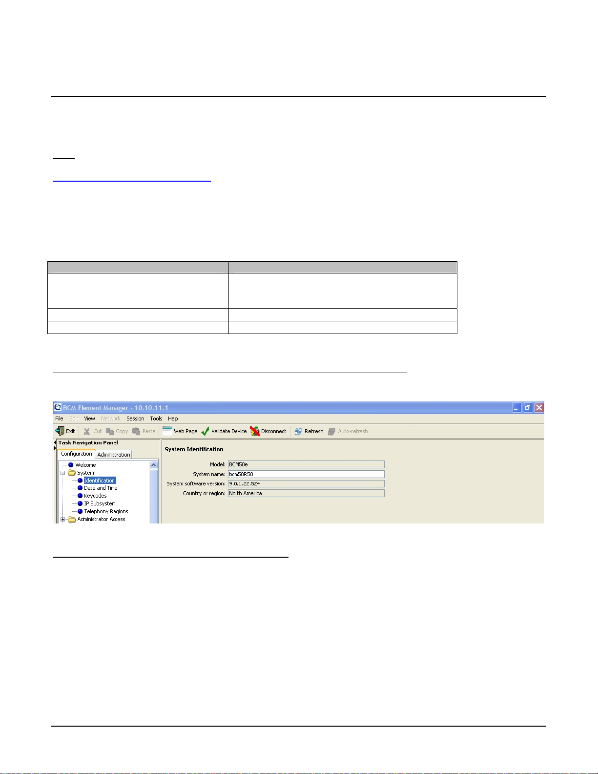
The Nortel Networks BCM must be running at least software version 9.0.1.22.XXX
BCM by viewing the following screen under Configuration
The following specifications have been considered
SIP RFC3261
IP Codec: G711U and G729; Packet (frame) size: 20ms
DTMF: in band, RFC2833
Caller ID: P-Asserted-ID as per RFC3325 (Remote-Party-ID header supported but not recommended -
deprecated-)
Caller ID blocking as per RFC3325 (Privacy id header)
:
Æ
System Æ Identification.
. You can check the version of
Re-Invite to 0.0.0.0 or a=sendonly are supported for on-hold
G711 pass-through used for fax transmissions
Early-Media is supported
G729 is the preferred codec on Allstream side
2009-00002508 Page 5 of 20
Page 6

BCM Rls 5.0 Configuration Guide For: MTS/Allstream SIP Trunking
3.0 Features
This section provides SIP Trunk features that are supported (or not supported) on the BCM Release 5.0 sy stem
with connected to MTS/Allstream’s SIP Trunk services.
3.1 Network Features Supported
MTS Allstream provides the following network features:
• G.729 CODEC Support in addition to G.711
• Survivability and Traffic Optimization Features
o Multi End Point Failover
o Multi End Point Overflow
o End Point Load Sharing
o PRI Failover
• Fax
o G.711 pass through is the only Fax protocol supported
• Multi CODEC Support (NRI&MRR)
o G.729 (voice compression) in addition to G.711
o G.729/ G.729a/ G.729b/ G.729a/b
o Each G.729 DTE requires 45 kbps
G.711 DTE requires 100 kbps
o Codec Negotiation
Requires customer’s IP PBX to negotiate both Codecs
IP PBX must revert to G.711 when Fax/ Modem Tone is detected
IP PBX must be able to fallback on G.711 when receiving/ making calls to G.711 only
customers (e.g. Cable co)
• Basic 911 Service
• Alternate Number
• Alternate Trunk Group
• Inbound Overflow TN
• Inbound Overflow Trunk
• PSTN Connection
• Service Level Objectives
• Temporary Local Redirect Services
2009-00002508 Page 6 of 20
Page 7

BCM Rls 5.0 Configuration Guide For: MTS/Allstream SIP Trunking
3.2 Technical Caveats
The following capabilities are not supported with this solution:
• T.38 fax is not supported
• Enhanced 911 is not
• 30ms packetization not supported
supported
2009-00002508 Page 7 of 20
Page 8

BCM Rls 5.0 Configuration Guide For: MTS/Allstream SIP Trunking
4.0 Network Diagram
The diagram below (Figure 1) shows the topology of the MTS/Allstream SIP Trunk service. In the diagram, there
is no NAT between the BCM (IP PBX) and MTS/Allstream SIP Trunk service SBC.
Figure 1
2009-00002508 Page 8 of 20
Page 9

BCM Rls 5.0 Configuration Guide For: MTS/Allstream SIP Trunking
5.0 System Configuration
This section provides procedures for configuring a SIP Trunk on BCM Rls. 5.0 to MTS/Allstream SIP Trunk
service.
5.1 BCM Configuration
In order to configure a SIP trunk between BCM Rls. 5.0 and MTS/Allstream do the following:
5.1.1 Line Pool Configuration
1. Under Configuration Æ Telephony Æ Dialing Plan; select Line Pools.
2. Select BlocA.
3. Click on the “Add” button to add DNs of phones that need to access the above line pool.
2009-00002508 Page 9 of 20
Page 10

BCM Rls 5.0 Configuration Guide For: MTS/Allstream SIP Trunking
5.1.2 Dial Plan Configuration
1. Under Configuration Æ Telephony Æ Dialing Plan Æ Public Network, define the Public Received
number length to “10”
digits
2. Set the Public Network Dialing Plan to Public (Unknown)
3. Under Configuration
4. Add a route by clicking on the Add button.
5. In the Add Route dialog box, provide an unused route and click on the OK button.
6. The Dialing Plan – Routing table will be displayed.
7. Click on the route just created
8. Under the Use Pool column, double click to select BlocA from the drop down list.
9. Under the DN Type column, double click to select Public (Unknown) from the drop down list
Æ
Telephony Æ Dialing Plan Æ Routing, and select the Routes tab
2009-00002508 Page 10 of 20
Page 11

BCM Rls 5.0 Configuration Guide For: MTS/Allstream SIP Trunking
10. Click on the Destination Codes tab.
11. Configure a destination code to route dialed digits by clicking on the Add button. Digits that begin with
this destination code will be presented to the SIP trunking component on the BCM for routing towards the
Service Provider.
12. In the Add Destination Code dialog box, enter a numeric number for the destination code and click on
the OK button.
13. Select the row representing the Destination Code entered in the previous step
14. Under Normal Route column, double click and enter the route entered in Step 4.
15. Under the Absorbed Length column, specify the number of digits that will be absorbed before sending
the rest of the digits to the service provider.
5.1.3 SIP Routing Table Configuration
There are two possible ways to configure the BCM to route outbound SIP calls to the Service Provider:
Æ
• Using the Routing Table tab found by clicking on IP Trunks module in Configuration
Telephony Resources.
• Using the SIP Proxy tab found by clicking on IP Trunks module in Configuration
Telephony Resources.
This guide illustrates how to do it using the Routing table. For details of how to use the SIP Proxy tab, see the
BCM configuration guides.
1. Under Configuration
click on the “Routing Table” tab.
Æ
Resources Æ Telephony Resources; select module type “IP Trunks” and
Resources Æ
Æ
Resources Æ
2009-00002508 Page 11 of 20
Page 12

BCM Rls 5.0 Configuration Guide For: MTS/Allstream SIP Trunking
2. Add a “Remote Gateway” by clicking on the “Add” button.
3. In the “Add Remote Gateway” dialog box that is displayed, configure the fields as follows:
• Description: Enter the logical name for the trunk destination
• Destination Digits: Enter digits that identify the remote system as the call destination.
• VoIP Protocol: SIP
• Domain: SIP Domain name of MTS/Allstream. This will be provided by MTS/Allstream.
• IP Address: Provide the IP address of the SBC. This will be provided by MTS/Allstream.
• Port: Provide the optional UDP port number to which the BCM will send SIP messages.
• GW Type: Set this field to Other.
• MCDN Protocol: Set to None.
• QoS Monitor: Leave unchecked
• Tx Threshold: Leave this field at its default value of 0.0
4. Click the OK button
2009-00002508 Page 12 of 20
Page 13

BCM Rls 5.0 Configuration Guide For: MTS/Allstream SIP Trunking
5.1.4 SIP Settings Configuration
1. Under Configuration Æ Resources Æ Telephony Resources: Select module type “IP Trunks” and
click on the “SIP Settings” tab
2. In the SIP Settings sections:
• Local Domain: Leave blank
• Disable maddr in Contact: Leave Un-Checked to enable maddr in Contact header
• Disable OPTIONS Caps: Leave Un-Checked to enable OPTIONS capability request by the
BCM
• Dynamic Payload: Enter 101 for MTS/Allstream SIP Trunk service
3. Leave the rest of parameters under the SIP Settings tab at the default values
2009-00002508 Page 13 of 20
Page 14

BCM Rls 5.0 Configuration Guide For: MTS/Allstream SIP Trunking
5.1.5 SIP Media Parameters Configuration
1. Under Configuration Æ Resources Æ Telephony Resources: Select module type “IP Trunks” and
click on the “SIP Media Parameters” tab.
2. In the Preferred Codecs section, configure G.711-uLaw as the first preferred codec and G.729 as the
second preferred codec.
3. In the codec Settings section, Disable Enable Voice Activity Detection.
4. In the codec Settings section, select 20ms as the payload size for both G.729 and G.711
5. Again in the codec settings Section set G.711 as the Fax transport.
5.1.6 IP Phones Media Parameters
1. Under Configuration
on “IP Terminals Global Settings”.
2. Set the “Default Codec” for IP phones to Auto and set the payload size (ms) for G.729 and G.711 to
20ms payload
2009-00002508 Page 14 of 20
Æ
Resources Æ Telephony Resources: Select module type “IP Sets” and click
Page 15

BCM Rls 5.0 Configuration Guide For: MTS/Allstream SIP Trunking
5.1.7 Configuring Incoming Calls from MTS/Allstream to BCM Rls. 5.0
This can be done in several ways;
1. The DID associated with the MTS/Allstream SIP account assigned to the BCM can be associated with
a “Target” line assigned to an individual phone or group of phone(s) and all calls to the DID will be
routed to those phone(s) respectively.
2. All calls to the DID associated with the MTS/Allstream SIP account assigned to the BCM can be
answered by the Auto Attendant (AA) and from there, a DN can be entered to reach phone on the
BCM
2009-00002508 Page 15 of 20
Page 16

BCM Rls 5.0 Configuration Guide For: MTS/Allstream SIP Trunking
5.1.7.1 Assigning DID to BCM Phones for Incoming Call
1. Navigate to Configuration
2. On the selected Target Line, set the “Pub. Received #” to the MTS/Allstream assigned DID.
3. Assign the DN of phones on the BCM that require an appearance on this target line. This will be the
phones that will be alerted when call to the MTS/Allstream assign DID is received.
a. Navigate to Configuration
Line configured in Step 2 above
b. Click on the Assigned DNs tab
c. Click the Add button to add the DN of the phone(s) to this Target Line.
Æ
TelephonyÆ Lines Æ Target Line and click on an unused target line
Æ
TelephonyÆ Lines Æ Target Line and click on the Target
d. OR Click on Active Sets, Select DN, Line Access tab, Line Assignment and Add Target
Line to “Appear & Ring” and select Check box Caller ID Set.
2009-00002508 Page 16 of 20
Page 17

BCM Rls 5.0 Configuration Guide For: MTS/Allstream SIP Trunking
5.1.7.2 Configuring AA to Answer Incoming Calls
Alternatively, the AA on the BCM can be configured to answer incoming calls and then call routed to a
target phone on the BCM by entering the extension of the phone at the AA prompt. To do this,
1. Navigate to Configuration
2. On the selected Target Line, set the “Pub. Received #” to the 10-digits of the MTS/Allstream
assigned DID.
3. Navigate to Configuration
4. Click on the Launch CallPilot Manager.
5. This launches a web browser to the BCM. Log in with the administrator credentials
6. On the left hand navigation menu, click on Auto Attendant
7. In the Line Administration web page, scroll down to the Target Line configured in Step 1.
8. Under the Command Column, click Change
9. In the Line Properties web page, select Auto-Attendant as the Answer Mode
10. Click the Submit button.
Æ
TelephonyÆ Lines Æ Target Line and click on an unused target line
Æ
ApplicationÆVoice Messaging/Contact Center
2009-00002508 Page 17 of 20
Page 18

BCM Rls 5.0 Configuration Guide For: MTS/Allstream SIP Trunking
2009-00002508 Page 18 of 20
Page 19

BCM Rls 5.0 Configuration Guide For: MTS/Allstream SIP Trunking
6.0 References
The following are useful references to assist in this solution:
1. Partner Information Center:
Document Number: NN40020-201: SIP Interoperability Considerations and Technical Specifications for Business
Communications Manager Release 5.0
2. BCM450 Technical Documentation”,
http://support.nortel.com/go/main.jsp?cscat=DOCUMENTATION&poid=19781
3. “BCM50 Technical Documentation“,
http://support.nortel.com/go/main.jsp?cscat=DOCUMENTATION&poid=15181
This document does not describe procedures to configure the BCM for advanced functionality. For more
information and procedures, please refer to the Nortel technical documentation found on the Nortel
website at http://support.nortel.com
.
2009-00002508 Page 19 of 20
Page 20

BCM Rls 5.0 Configuration Guide For: MTS/Allstream SIP Trunking
************************************************END************************************************
The information in this document is subject to change without notice. The statements, configurations,
technical data, and recommendations in this document are believed to be accurate and reliable, but are
presented without express or implied warranty. Users must take full responsibility for their applications
of any products specified in this document.
The information in this document is proprietary to Nortel Networks. Nortel, the Nortel logo and the
Globemark are trademarks of Nortel Networks.
2009-00002508 Page 20 of 20
 Loading...