

Page 1
BSGX4e
Business Gateway
User Guide
Release 01.01
Page 2

Trademarks
Nortel, the Nortel logo, and the Globemark are trademarks of Nortel Networks.
All other trademarks appearing in this guide are the exclusive property of their
respective owners.
Hardware Notice
WARNING: Before working on this equipment, be aware of good safety practices
and the hazards involved with electrical circuits.
WARNING: To reduce risk of injury, fire hazard, and electric shock, do not install
the unit near a damp location.
CAUTION: Do not connect the FXS port (labeled PHONE) to the central office line.
CAUTION: To reduce the risk of fire, use only number 26 AWG or larger UL Listed
or CSA Certified telecommunication line cord for all network and
telecommunication connections.
2 BSGX4e Business Gateway User Guide
NN47928-102 Release 01.01
Page 3

C
ONTENTS
ABOUT THIS GUIDE
Audience ........................................................................... 23
Organization....................................................................... 23
Conventions ....................................................................... 25
Command Prompt Convention................................................ 25
Text Font Conventions......................................................... 25
Documentation.................................................................... 26
How to get help................................................................... 26
Getting Help from the Nortel Web site ..................................... 26
Getting Help over the phone from a Nortel Solutions Center ........... 26
Getting Help from a specialist by using an Express Routing Code ...... 27
Getting Help through a Nortel distributor or reseller .................... 27
1
CONNECTING TO THE DEVICE
Network Role...................................................................... 29
Device Features................................................................... 30
Connecting to the Unit .......................................................... 32
Finding an IP Address using a Console Session ............................. 32
Remote Administration Services ............................................. 33
Telnet Access...................................................................... 34
Telnet Configuration Command .............................................. 34
Telnet Configuration Example ................................................ 35
Show Telnet Configuration.................................................... 35
Telnet Client Command........................................................ 35
Telnet Session Example........................................................ 35
SSH Server ..................................... ..... ..... ..... ..................... 36
Digital Signature Algorithm (DSA) Host Keys ............................... 36
SSH Configuration Command ................................................. 36
SSH Example .................................................... ..... ..... ...... 37
Show SSH Configuration ....................................................... 37
Regenerate SSH keys........................................................... 37
Upload Public Key.............................................................. 38
Web Server ........................................................................ 38
Web Server Configuration Command........................................ 39
Disable Web Server Example.................................................. 39
Show Web Server Configuration.............................................. 39
Show Web Server Statistics ................................................... 40
SSL .................................................................................. 40
SSL Key........................................................................... 40
SSL CSR........................................................................... 41
SSL Certificate .................................................................. 42
SSL Configuration Example.................................................... 43
Show SSL Configuration........................................................ 43
Page 4

2 INITIAL SETUP
Setting the Time ..................................................................47
Show the Current Time.........................................................47
Setting the Time Manually.....................................................47
Setting the Time through an SNTP Server...................................48
Watchdog Reset Timer ...........................................................49
Watchdog Timer Command ....................................................49
Watchdog Timer Example......................................................50
Show Watchdog Configuration ................................................50
DNS Client.............................................................. ..... .......50
DNS Client Configuration Command..........................................50
DNS Client Configuration Example ...........................................51
Show DNS Client Configuration ...............................................52
Check DNS Server Accessibility ...............................................52
Initial Settings .....................................................................52
3
USER MANAGEMENT
User Management Features......................................................57
Password Entry ....................................................................58
Failed log on Attempts.........................................................58
Changing a Password ...........................................................59
Showing Active Users .............................................................60
User Accounts, Groups and Rights..............................................61
User Configuration Commands................................................61
User Accounts......................................................................61
Add User Account Example....................................................63
Show User Account .............................................................63
Deleting a User Account .......................................................63
User Groups ........................................................................64
Add User Group Example ......................................................65
Show a User Group..............................................................65
Deleting a User Group..........................................................65
User Rights .........................................................................66
Command Authority ............................................................66
Configuration Requirements...................................................66
Configuration Command .......................................................67
Add User Rights Example ......................................................67
Show User Rights Record.......................................................68
Deleting a User Rights Record.................................................68
Radius Authentication............................................................68
Configuration Requirements...................................................69
Configuration Steps.............................................................69
Radius Authentication Records................................................69
Example of Configuring a Radius Authentication Record .................70
Show Radius Authentication Records ........................................71
Radius Activity Logs ............................................................71
TACACS+ Authentication .........................................................71
Configuration Steps.............................................................72
4 BSGX4e Business Gateway User Guide
NN47928-102 Release 01.01
Page 5

TACACS+ Authentication Records ............................................ 72
Example of Configuring a TACACS+ Authentication Record.............. 73
Show TACACS+ Authentication Records ..................................... 73
TACACS+ Activity Logs ......................................................... 74
TACACS+ Authentication......................................................... 74
Configuration Requirements.................................................. 74
TACACS+ Authentication Records ............................................ 75
Example of Configuring a TACACS+ Authentication Record.............. 75
4
COMMAND INTERFACE
Command Entry................................................................... 77
Logging Off ....... .... ............................................................. 78
Exit Command .................................................................. 78
Customizing the Command Session ............................................ 78
Changing the Terminal Settings .............................................. 79
Saving Configuration Changes .................................................. 79
Showing the Configuration ...................................................... 80
Defining Auto Run Commands .................................................. 80
Online Help........................................................................ 81
General Help.................................................................... 81
Specific Help.................................................................... 81
Interactive Mode.................................................................. 82
CLI Command Syntax............................................................. 83
Parameter Values............................................................... 84
Command Keyword NO ............................................. ..... ..... . 84
Command Keyword ALL.................................................. ..... . 85
Maintenance Commands...... ..... ..... ..... ..... ............................... 86
Maintenance Command Syntax............................................... 86
Maintenance Command Help ............................ ..... ..... ..... ..... . 86
List of Maintenance Commands .............................................. 86
Debug Commands....................................... ..... ..... ..... ..... ..... . 88
Debug Command Syntax............................. ..... ..... ................ 88
Debug Command Help . ........................................................ 88
List of Debug Commands ...................................................... 88
5
WAN INTERFACE CONFIGURATION
Ethernet WAN Port and Interface.............................................. 91
WAN Ports........................................................................ 91
WAN Interface (eth0) .......................................................... 92
eth0 Configuration Command ................................................ 92
Show eth0 Configuration ...................................................... 94
eth0 Statistics................................................................... 94
6
LAN SWITCH CONFIGURATION
Introduction ....................................................................... 97
LAN Switch Ports.................................................................. 97
LAN Port Configuration Command ........................................... 98
LAN Port Configuration Examples............................................ 98
BSGX4e Business Gateway User Guide 5
Release 01.01 NN47928-102
Page 6

Show Port Configuration .......................................................99
Show Port Status ................................................................99
Show Port Statistics.............................................................100
LAN Interface (eth1)..............................................................102
eth1 Configuration Command.................................................102
Configure eth1 Interface Example ...........................................102
Show eth1 Configuration.......................................................103
ARL Configuration.................................................................104
ARL Configuration Command..................................................104
Show ARL Table..................................................................105
Remove an ARL Entry...........................................................106
Flush ARL Table..................................................................106
Layer 2 QoS ........................................................................106
Priority Queues..................................................................107
Selecting Layer 2 QoS Settings................................................108
Mapping Port Numbers to Priority Queues ..................................108
Mapping IEEE 802.1p Tags to Priority Queues...............................108
Mapping ToS/DiffServ Tags to Priority Queues..............................109
Layer 2 QoS Configuration Example..........................................109
Show Layer 2 QoS Configuration..............................................109
7
VLAN CONFIGURATION
Assigning Ports to a VLAN........................................................111
Packet Tagging...................................................................112
VLAN Port Assignment Command.............................................112
VLAN Port Assignment Examples..............................................112
Show VLAN Port Assignments..................................................113
Delete VLAN Port Assignment.................................................113
Configuring a VLAN Interface....................................................114
Configuration Constraints......................................................114
Virtual Interface Configuration ...............................................114
VLAN IP Address Assignment ..................................................115
Virtual Interface Configuration Examples...................................116
Modifying or Deleting a VLAN ...................................................117
8
ROUTING CONFIGURATION
Introduction........................................................................121
Configuring ARP ...................................................................122
ARP Entry Configuration Command ..........................................122
ARP Entry Example..............................................................122
Show ARP Table..................................................................122
Delete ARP Entry...................... ..... ..... ................................123
Flush ARP Table .................................................................123
Protecting ARP Traffic..........................................................123
Configuring Static Routes ........................................................124
Route Configuration Command ...............................................124
Static Route Examples..........................................................125
Show Route Table ...............................................................125
6 BSGX4e Business Gateway User Guide
NN47928-102 Release 01.01
Page 7

Delete a Static Route.......................................................... 126
Starting the RIP Daemon......................................................... 126
RIP Constraints.................................................................. 126
RIP Daemon Command......................................................... 126
RIP Daemon Example .......................................................... 127
Show RIP Status................................................................. 127
Show RIP Routes................................................................ 127
9
SECURITY CONFIGURATION
Secure Traffic Processing........................................................ 129
Firewall Security Policies........................................................ 130
Initial Firewall Security Policies.............................................. 130
Configuration Constraints ..................................................... 130
Security Policy Sequence...................................................... 130
Security Policy Configuration Command.................................... 131
Firewall Security Policy Example ............................................ 132
Show Firewall Security Policies .............................................. 132
Remove a Firewall Security Policy ........................................... 132
Show Firewall Log Entries..................................................... 132
Connection Time-outs............................................................ 133
Connection Timeout Command............................................... 133
Show Timeout Settings ........................................................ 133
NAT/ALG ........................................................................... 134
Configuring NAT................................................................. 134
Enable NAT on the WAN Interface............................................ 135
Configuring NAT Policies................... ..... ..... ..... ..... ..... ........... 135
Configuring NAT Public Addresses............................................ 136
Port Forwarding................................................................. 137
Address Forwarding ............................................................ 138
Static NAT Forwarding ......................................................... 138
Show NAT Policies .............................................................. 139
ALG Configuration.............................................................. 140
IDS................................................................................... 140
Attack Types..................................................................... 141
Packet Anomaly Protection ................................................... 141
Flood Protection................................................................ 143
Scan Protection................................................................. 146
Spoof Protection................................................................ 147
IDS Statistics .................................................................... 149
Clear IDS Statistics ............................................................. 150
Show IDS Log Entries........................................................... 150
10
VPN CONFIGURATION
VPN Support ....................................................................... 153
IKE .................................................................................. 154
IKE Policies ...................................................................... 155
IKE Lifetime Parameters....................................................... 155
IKE Preshared Key Records.................................................... 156
BSGX4e Business Gateway User Guide 7
Release 01.01 NN47928-102
Page 8

Show IKE Security Associations ...............................................157
Show IKE Statistics..............................................................158
IPsec.................................................................................158
IPsec Parameters................................................................159
IPsec Proposals ..................................................................160
IPsec Policies ....................................................................160
Show IPsec Security Associations .............................................162
IPsec Statistics...................................................................163
VPN Configuration Examples ....................................................163
Office-to-Office VPN Example ................................................163
ISP Tunnel Example .............................................................166
Configuring a VPN.................................................................169
VPN support on BSGX4e ..........................................................174
Example ..........................................................................175
Configuration of BSGX4e using a single tunnel .............................175
Configuration of Cisco..........................................................176
Troubleshooting on BSGX4e..................................... ..... ..... ..... ..177
11
GOS CONFIGURATION
Introduction to GoS ...............................................................181
Quality Groups...................................................................182
GoS Classes....................................... ..... ..... ......................182
Traffic Policing ..................................................................183
Configuring GoS .................................................................185
Configuring a GoS Link ...........................................................186
GoS Link Example.......................... .....................................186
Show the GoS Link ..............................................................186
Delete GoS Link .................................................................187
Configuring Quality Groups ......................................................187
Configuration Constraints......................................................187
Downgraded and Dropped Packets ...........................................187
Default Best Effort Quality Group............................................188
Quality Group Command.......................................................188
Quality Group Examples .......................................................189
Show Quality Groups ...........................................................190
Delete a Quality Group.........................................................190
Assigning Traffic Flows to Quality Groups.....................................190
VoIP Traffic Protection .........................................................191
ARP Traffic Protection..........................................................191
Traffic Protection by Security Policy.........................................191
GoS Security Policy Examples................. ..... ..... ..... ..... ............192
Show GoS Security Policies ....................................................193
Delete a Security Policy........................................................193
GoS Statistics ...................................... ..... ..... ..... .................193
Cumulative Statistics...........................................................193
Clearing GoS Cumulative Statistics...........................................195
Instantaneous Statistics........................................................195
Configuring QoS....................................................................197
Example ..........................................................................200
8 BSGX4e Business Gateway User Guide
NN47928-102 Release 01.01
Page 9

Configuring Layer 2 QoS....................................................... 201
Configuring Layer 3 QoS....................................................... 204
12
MGCP CONFIGURATION
Introduction to MGCP ............................................................ 209
MGCP Session Controller ...................................................... 210
MGCP Gateway.................................................................. 211
MGCP Configuration Steps .................................................... 211
MGCP Call Servers ................................................................ 212
Call Server Failover ............................................................ 212
MGCP Server Profile Command............................................... 213
MGCP Server Profile Examples................................................ 213
Show Server Settings........................................................... 214
Delete MGCP Server Profile................................................... 214
Show MGCP Server Status ..................................................... 214
MGCP Session Controller Configuration ....................................... 215
MGCP Signaling Proxy (MSP) .................................................. 216
Endpoint Status Handling (ESH) .............................................. 220
MGCP Gateway.................................................................... 222
Configuring MGCP Settings for the Gateway ............................... 222
Configuring the MGCP Gateway .............................................. 223
MGCP Endpoints................................................................... 227
Preparing Endpoints for Registration ........................................ 227
Verify Endpoint Registration.................................................. 228
13
VOIP CONFIGURATION
Media Bridge (MBR)............................................................... 229
Media Settings Command........................................... ..... ..... . 229
Media Settings Example ....................................................... 230
Show Media Settings ........................................................... 230
Show Media Status ............................................................. 230
Show Media Connection Statistics ........................................... 231
Access Control List (ACL)........................................................ 232
Access Control List Command ................................................ 233
ACL Entry Example............................................................. 233
Show ACL ........................................................................ 234
Cisco Discovery Protocol (CDP)................................................. 234
Show CDP Entry................................................................. 234
Show CDP Neighbors ........................................................... 235
Show CDP Statistics ............................................................ 236
Call Admission Control (CAC) ................................................... 236
VoIP Bandwidth Requirements................................................ 236
Show Call Admission Settings................................................. 237
FXS Port Configuration........................................................... 238
Country Code and Unit Name Setting ....................................... 239
Jitter Buffer Settings .......................................................... 240
Call Progress Tones............................................................. 241
DSP Gain Settings............................................................... 243
BSGX4e Business Gateway User Guide 9
Release 01.01 NN47928-102
Page 10

Line Impedance Settings.......................................................243
Electrical Status.................................................................244
Line Fault Testing ...............................................................245
Voice Quality Monitoring (VQM).................................................247
Monitored Calls....................................... ..... ..... ..... ..... .......248
VQM Analyser Command ........ ..... .......................................... 249
VQM Analyser Example............................................. ..... .......250
Show VQM Analyser Configuration............................................250
Show VQM Call Summary.......................................................250
Voice Quality Statistics.........................................................251
Alarm Log Entries ...............................................................252
Alarm Statistics..................................................................252
Call Records........................................................................253
Show Current Calls..............................................................253
Show Call History ...............................................................254
14
LOCAL CALL ROUTING
VoIP Service Interruption ........................................................255
Local Call Routing (LCR) Mode ..................................................256
LCR Configuration...............................................................256
LCR Account Configuration ....................................................256
LCR Settings......................................................................257
FxO Gain and Impedance Settings............................................259
Show LCR Status.................................................................262
Show LCR Connections .........................................................262
15
SIP CONFIGURATION
Introduction to SIP ................................................................263
SIP Session Controller .................................... ..... ..... ............264
SIP Gateway............................ .......................................... 265
SIP Configuration Steps .............. ..... ..... ..... ..... ..... .................265
SIP Call Server Access ............................................................266
Call Server Failover.............................................................266
Additional Inbound Servers....................................................266
SIP Server Profile Command...................................................267
SIP Server Profile Examples ........................ ..... ..... ..... ..... .......267
Show SIP Server Settings.......................................................269
Delete SIP Server Profile.......................................................270
Show SIP Server Status .........................................................270
SIP Session Controller.............................................................271
SIP Signaling Proxy (SSP).......................................................272
Session Controller Setting Command ........................................272
Show SIP Session Controller Settings.........................................273
Show SIP Session Controller Status...........................................274
Show SIP Signaling Statistics ..................................................274
Show SIP Call Statistics.........................................................275
Show SIP Call Records ..........................................................276
Show Registered Endpoints....................................................276
10 BSGX4e Business Gateway User Guide
NN47928-102 Release 01.01
Page 11

Endpoint Status Handling (ESH) .............................................. 277
SIP Gateway ....................................................................... 278
SIP Settings for the Gateway ................................................. 278
SIP Gateway Configuration.................................................... 280
Numbering Plan for the Gateway ............................................ 284
SIP Endpoints...................................................................... 288
Preparing Endpoints for Registration ........................................ 288
Verify Endpoint Registration.................................................. 289
IP Address Change.............................................................. 289
Configuring SIP.................................................................... 290
Step 1-Configure BSGX4e Session Controller ................................. 292
Configuration of the IP Network ............................................. 292
Data service configuration for the LAN VoIP phones: DHCP, SNTP, and TFTP296
Configuration of the SIP voice services offered to LAN VoIP phones .. 297
Step 2-Configuring the BSGX4e User Agent................................... 299
Step 3-Configure LAN VoIP phones (Example using Cisco 7960) .......... 300
Step 4-Check the overall configuration ....................................... 301
Step 5-Make calls ................................................................. 302
Annex A-Configuration example for Cisco 7960 SIP phone................. 303
Annex B-Call Admission Controller algorithm............................... 306
16
VOIP SERVICES AND RELAYS
DHCP Server ....................................................................... 309
Default DHCP Server Configuration.......................................... 309
DHCP Server Configuration Command....................................... 310
DHCP Server Configuration Example ........................................ 311
Show DHCP Server Configuration ............................................ 311
Show DHCP Leases.............................................................. 312
DHCP Relay ........................................................................ 312
DHCP Relay Command ......................................................... 312
DHCP Relay Example........................................................... 313
Show DHCP Relay Settings .................................................... 313
DNS Relay .......................................................................... 313
DNS Relay Command........................................................... 313
DNS Relay Example............................................................. 314
Show DNS Relay Settings ...................................................... 314
Show DNS Sessions.............................................................. 314
Show DNS Relay Cache......................................................... 314
SNTP Relay......................................................................... 315
SNTP Relay Command.......................................................... 315
SNTP Relay Example ........................................................... 315
Show SNTP Settings ............................................................ 316
Show SNTP Sessions ............................................................ 316
TFTP Relay......................................................................... 316
TFTP Relay Command.......................................................... 316
TFTP Relay Settings Example................................................. 317
Show TFTP Relay Settings..................................................... 317
Show TFTP Sessions ............................................................ 317
TFTP File Cache................................................................... 318
BSGX4e Business Gateway User Guide 11
Release 01.01 NN47928-102
Page 12

TFTP Cache Command .........................................................318
Specifying Files to be Cached.................................................318
TFTP Cache Example ...........................................................319
Show TFTP Cache Settings and Usage .......................................319
Show TFTP Cache Contents....................................................319
Delete Files to be Cached .....................................................320
Clear TFTP Cache ...............................................................320
17
MONITORING
Show System Exceptions .........................................................321
Show Hardware Information.....................................................322
Show System Status...............................................................322
Show System Operation Summary ..............................................323
Audit Logging ......................................................................324
Audit Log Command ............................................................324
Show Audit Log Status..........................................................324
Show Audit Log Entries.........................................................325
Clear Audit Log..................................................................325
Module Logging ....................................................................325
Logging Level Command .......................................................326
Mapping Log Destinations......................................................327
Show Module Log Entries.......................................................329
Configure Log Server ...........................................................329
Ethernet Interface Statistics ....................................................331
IP Stack Statistics .................................................................331
IP Statistics ......................................................................332
ICMP Statistics...................................................................333
UDP Statistics....................................................................335
TCP Statistics....................................................................335
18
MONITORING TOOLS
Port Mirroring......................................................................339
Port Mirroring Constraints .....................................................339
Port Mirroring Command.......................................................339
Mirroring Configuration Example ....................... ..... ..... ..... ..... ..340
Show Mirroring Configuration .................................................340
Deleting a Port Mirroring Entry ...............................................340
Protocol Monitoring (PMON) .....................................................340
Enable PMON Command........................................................341
PMON Trace Command .........................................................341
PMON Configuration Example .................................................342
Show PMON Status ..............................................................342
Show PMON Traces..............................................................342
Show PMON Trace Statistics ...................................................343
Clear PMON Trace Statistics...................................................343
Netflow Exporter..................................................................343
Netflow Exporter Command...................................................344
Netflow Filter Command.......................................................345
12 BSGX4e Business Gateway User Guide
NN47928-102 Release 01.01
Page 13

Netflow Configuration Example.............................................. 345
Show Netflow Status........................................................... 346
Show Netflow Filters........................................................... 346
Show Netflow Statistics ....................................................... 346
Clear Netflow Statistics ....................................................... 346
SNMP Agent................................................... ..... ..... ..... ..... . 347
SNMP Configuration Command .......................... ..... ................ 347
SNMP Community Command.............. ..... ............................... 348
SNMP Agent Configuration Example ......................................... 348
Show SNMP Agent Configuration ............................................. 349
Show SNMP Community Configuration ...................................... 349
Show SNMP Agent Statistics................................................... 349
Clear SNMP Statistics .......................................................... 351
SNMP Traps ....................................... ..... ..... ..... ..... ..... ...... 351
Copying Trap MIB Data......................................................... 352
TCPdump Command.............................................................. 352
TCPDump Command Options ................................................. 352
Limited Capture Example ..................................................... 354
Ping Command .................................................................... 355
Ping Example.................................................................... 356
Traceroute Command............................................................ 356
Traceroute Example............................................................ 357
19
SOFTWARE UPGRADES
File System ........................................................................ 359
File System Navigation ........................................................ 359
File System Management...................................................... 360
Software Upgrade Procedures .................................................. 362
Device Software ................................................................ 362
Check Current Software Versions ............................................ 362
Web UI Upgrade Procedure ..................................................... 363
Requirements ................................................................... 363
Save the Current Configuration .............................................. 363
Upgrade Software through Web UI........................................... 365
Change Default Application Image........................................... 368
View Bootloader Version ...................................................... 369
Restore the Configuration...................... ............................... 369
SFTP Upgrade Procedure ........................................................ 371
Listing the Configuration ........................................................ 374
A
WEB USER INTERFACE
...................................................................................... 379
Web UI Features .................................................................. 380
Logging on to the Web UI........................................................ 380
Access Requirements........................................................... 381
Log on Procedure................................ ..... ..... ..................... 381
Web UI Screen Structure ........................................................ 382
Menus............................................................................. 382
BSGX4e Business Gateway User Guide 13
Release 01.01 NN47928-102
Page 14

Help Icons........................................................................382
Operations Menu ................................................................383
Web UI Menus......................................................................384
Configuration Example ...........................................................388
Monitoring Example...............................................................390
Wizards Example ..................................................................391
Exit Web UI.........................................................................396
B
THIRD PARTY SOFTWARE
Software Applications ............................................................399
C
SSH FUNCTIONALITY
Introduction........................................................................401
SSH Server Functionality .........................................................401
SFTP.................................................................................402
Authentication.....................................................................402
Host Keys.........................................................................403
Remote Log on...................................................................403
Service Functions..................................................................403
SSH Service.......................................................................403
SFTP Service .....................................................................404
SSH System Architecture.........................................................404
SSH-TRANS .......................................................................404
SSH-AUTH ........................................................................405
SSH-CONNECTION ...............................................................405
D
TCPDUMP EXPRESSIONS
Introduction........................................................................407
Expressions.........................................................................407
Primitives...........................................................................407
STANDARDS COMPLIANCE
E
Data Standards ....................................................................411
Switching.........................................................................411
Routing ...........................................................................411
Security...........................................................................412
Quality of Service...............................................................412
Services...........................................................................413
Monitoring........................................................................413
Voice Standards ...................................................................414
SIP Session Controller .................................... ..... ..... ............414
MGCP Session Controller.......................................................415
SIP User Agent (Integrated Gateway)........................................415
MGCP User Agent (Integrated Gateway).....................................416
F
RULE COMPLIANCE
FCC Compliance (U.S.) ...........................................................419
14 BSGX4e Business Gateway User Guide
NN47928-102 Release 01.01
Page 15

FCC Telecom Statement....................................................... 419
Declaration of Conformity .................................................... 420
Equipment Attachment Regulations (Canada) ............................. 421
Canadian Department of Communications Statement.................... 421
Supplementary Information................................................... 421
G
COPYRIGHT INFORMATION
...................................................................................... 423
GLOSSARY
H
...................................................................................... 429
INDEX
...................................................................................... 433
BSGX4e Business Gateway User Guide 15
Release 01.01 NN47928-102
Page 16

16 BSGX4e Business Gateway User Guide
NN47928-102 Release 01.01
Page 17

T
ABLES
1 User Guide Organization.................................................. 23
2 Text Conventions .......................................................... 25
3 Telnet Server Configuration Parameters................................ 35
4 Telnet Parameters......................................................... 35
5 SSH Configuration Parameters............................................ 37
6 Web Server Configuration Parameters .................................. 39
7 Web Server Statistics ...................................................... 40
8 SSL Key Configuration Parameters....................................... 41
9 SSL CSR Configuration Parameters....................................... 41
10 SSL Certificate Configuration Parameters .............................. 43
11 SNTP Server Configuration Parameters ................................. 48
12 System Watchdog Configuration Parameters........................... 49
13 DNS Client Configuration Parameters ................................... 51
14 Initial Settings............................................................... 53
15 Config User Commands .................................................... 61
16 User Account Configuration Parameters................................ 62
17 User Group Configuration Parameters .................................. 64
18 User Rights Parameters.................................................... 67
19 Radius Authentication Record Parameters ............................. 70
20 TACACS+ Authentication Record Parameters .......................... 73
21 TACACS+ Authentication Record Parameters .......................... 75
22 Terminal Session Parameters............................................. 79
23 Autorun Command Parameters........................................... 80
24 eth0 Parameters............................................................ 92
25 LAN Port Parameters....................................................... 98
26 LAN Port Summary Statistics.............................................. 100
27 LAN Interface Parameters................................................. 102
28 ARL Parameters............................................................. 104
29 Default Priority Queues............................... ..................... 107
30 Layer 2 QoS Setting Parameters......................................... 108
31 Layer 2 QoS Port Mapping Parameters .................................. 108
32 Layer 2 QoS 802.1p Tag Mapping Parameters.......................... 108
33 Layer 2 QoS DiffServ/ToS Mapping Parameters........................ 109
34 VLAN Configuration Parameters.......................................... 112
35 Virtual Interface Parameters ............................................. 114
36 IP Address Assignment Parameters ...................................... 115
37 ARP Route Parameters..................................................... 122
38 Route Configuration Parameters......................................... 125
39 RIP Daemon Parameters................................................... 127
40 Traffic Classification....................................................... 129
Page 18

41 Security Policy Parameters................................................ 131
42 Connection Configuration Parameters................................... 133
43 NAT Status Parameters..................................................... 135
44 NAT Policy Configuration Parameters.................................... 136
45 ALG Configuration Parameters............................................ 140
46 Protocols to which IDS Attack Protection Applies...................... 141
47 Packet Anomaly Attacks ................................................... 142
48 Packet Fragment Anomaly Parameters .................................. 142
49 Flood Detection Activation Parameters ................................. 144
50 Default Flood Threshold Values........................................... 145
51 Flood Threshold Setting Parameters ..................................... 146
52 IDS Scan Configuration Parameters....................................... 147
53 Default Trust Settings for Interfaces..................................... 148
54 IDS Spoof Configuration Parameters ..................................... 148
55 IKE Parameters .............................................................. 155
56 IKE Preshared Configuration Parameters................................ 156
57 IKE SAs.......................................... 158
58 IPsec Parameters........................................... ..... ..... ..... .. 159
59 IPsec Proposal Parameters................. ..... ..... ..... ..... ..... ..... .. 160
60 IPsec Policy Parameters.................................................... 161
61 Network information ....................................................... 169
62 Performance of each module with QoS running concurrently........ 171
63 ESP Statistics................................................................. 179
64 GoS Link Configuration Parameters ...................................... 186
65 GoS Group Configuration Parameters.................................... 188
66 GoS Cumulative Statistics.................................................. 194
67 GoS Instantaneous Statistics .............................................. 196
68 Network Information ....................................................... 197
69 Server Information.......................................................... 197
70 MGCP Server Profile Parameters.......................................... 213
71 MGCP Session Controller Parameters .................................... 216
72 MGCP Gateway Parameters................................................ 223
73 MGCP Gateway Configuration Parameters .............................. 224
74 Media Stream Parameters ................................................. 230
75 Voice ACL Parameters...................................................... 233
76 System Info Parameters.................................................... 239
77 Voice Jitter Buffer Configuration Parameters.......................... 240
78 Call Progress Tone Parameters ........................................... 242
79 Call Analyser Configuration Parameters................................. 249
80 Call Record Fields........................................................... 253
81 LCR Account Parameters................................................... 257
82 LCR Configuration Parameters ............................................ 258
18 BSGX4e Business Gateway User Guide
NN47928-102 Release 01.01
Page 19

83 AC Impedance Register Values ........................................... 261
84 SIP Server Profile Parameters ............................................ 267
85 SIP Session Controller Parameters ....................................... 273
86 SIP Gateway Parameters .................................................. 279
87 SIP Gateway Configuration Parameters................................. 281
88 SIP Numbering Plan Parameters.......................................... 284
89 Network Information....................................................... 291
90 Server Information ......................................................... 291
91 DHCP Server Configuration Parameters................................. 310
92 DHCP Relay Parameters ................................................... 312
93 DNS Relay Parameters ..................................................... 314
94 SNTP Relay Configuration Parameters .................................. 315
95 TFTP Relay Configuration Parameters .................................. 316
96 TFTP Cache Configuration Parameters.................................. 318
97 TFTP Files Configuration Parameters.................................... 319
98 System Exception Information Fields.................................... 321
99 Message Severity........................................................... 326
100 Logging Modules Configuration Parameters ............................ 326
101 Log Destination Map Parameters......................................... 328
102 Log Server Parameters..................................................... 330
103 IP Statistics.................................................................. 332
104 ICMP Statistics .............................................................. 334
105 UDP Statistics ............................................................... 335
106 TCP Statistics ............................................................... 336
107 Mirroring Parameters ...................................................... 340
108 PMON Trace Parameters................................................... 342
109 Netflow Agent Configuration Parameters............................... 344
110 Netflow Filter Configuration Parameters ............................... 345
111 SNMP Agent Configuration Parameters.................................. 347
112 SNMP Community Configuration Parameters ........................... 348
113 SNMP Data Fields ........................................................... 349
114 SNMP Agent Statistics...................................................... 350
115 SNMP Traps Configuration Parameters .................................. 351
116 TCPDump Options .......................................................... 353
117 Ping Options................................................................. 355
118 Traceroute Options......................................................... 356
119 Ls Configuration Options .................................................. 360
120 rm Parameters .............................................................. 361
121 Web UI Menus ............................................................... 385
122 Switching .................................................................... 411
123 Routing....................................................................... 411
124 NAT Security ................................................................ 412
BSGX4e Business Gateway User Guide 19
Release 01.01 NN47928-102
Page 20

125 IKE Security .................................................................. 412
126 IPsec Security................. ..... ..... ..... ..... ..... ...................... 412
127 Quality of Service ........................................................... 412
128 Services....................................................................... 413
129 Monitoring.................................................................... 413
130 SIP Session Controller ...................................................... 414
131 MGCP Session Controller ................................................... 415
132 SIP User Agent ............................................................... 415
133 MGCP User Agent............................................................ 416
20 BSGX4e Business Gateway User Guide
NN47928-102 Release 01.01
Page 21

F
IGURES
1 BSGX4e Connectivity......................................................... 30
2 Connect to the Console Port ............................................... 32
3 Head office and branch office traffic .................................... 169
4 Logical path of the routing engine ....................................... 170
5 VPN operations when NAT is disabled.................................... 172
6 VPN operations when NAT is enabled .................................... 173
7 Flow types.................................................................... 173
8 Capacity Reduction Between Fast Ethernet and WAN.................. 181
9 GoS Classes.................................................................... 183
10 Strict Policing................................................................. 184
11 CAR Policing................................................................... 185
12 Logical path.............................................. ..... ..... ........... 198
13 Hardware path................................................................ 199
14 MGCP Network Layout....................................................... 210
15 Flows that VQM Measures................................................... 248
16 VoIP Service Interruption ........................................ ..... ..... . 255
17 SIP Network Layout .......................................................... 264
18 Main Page...................................................................... 379
19 log on Window................................................................ 381
20 Menu Bar....................................................................... 384
Page 22

22 BSGX4e Business Gateway User Guide
NN47928-102 Release 01.01
Page 23

A
BOUT
This preface describes the intended audience for this guide, how this guide is
organized, its conventions, and access to customer support.
T
HIS
G
UIDE
Audience
This document provides guidelines for configuring and monitoring the BSGX4e
Business Gateway device. It is designed for network managers, administrators, and
technicians who are responsible for the management of networking equipment in
enterprise and service provider environments. Knowledge of telecommunication
technologies and standards, including telephony and Internet protocols, is assumed.
For installation information, see the BSGX4e Business Gateway Installation Guide
(see “Documentation” (page 26)).
Organization
The following table describes the content and organization of this guide.
Table 1. User Guide Organization
Chapter Title Content
Part I: BSGX4e Use
1 Connecting to
the Device
2 Initial Setup How to set the time, restart timer and Domain
3 User
Management
4 Command
Interface
5 WAN Interface
Configuration
6 LAN Switch
Configuration
Device overview and the means of remote access to
the unit.
Name Service (DNS) server, and a list of initial
configuration settings.
How to create, modify, remove, and monitor user
access to the device.
How to use commands, including accessing online
help, command syntax, showing and saving
configurations, and defining autorun commands.
Part II: Interfaces and Switch Ports
How to configure the Wide Area Network (WAN)
interface.
How to configure the Local Area Network (LAN)
switch ports and the LAN interface. Topics include
Address Resolution Logic (ARL) and layer 2 Quality
of Service (QoS).
7 VLAN
Configuration
How to configure virtual LANs (VLANs).
Page 24

Table 1. User Guide Organization (continued)
Chapter Title Content
8 Routing
Configuration
9 Security
Configuration
10 VPN
Configuration
11 GoS
Configuration
12 SIP
Configuration
13 MGCP
Configuration
14 VoIP
Configuration
How to manage an Address Resolution Protocol
(ARP) table, configure static routes, and start the
Routing Information Protocol (RIP) daemon.
Part III: Traffic Protection
Security topics, including the firewall, Network
Address Translation (NAT), Application Layer
Gateway (ALG), and Intrusion Detection System
(IDS).
How to configure Virtual Private Networks (VPN)
using IP security (IPsec) and Internet Key Exchange
(IKE).
How to configure Nortel’s layer 3 QoS feature,
Guarantee of Service (GoS).
Part IV: VoIP
How to configure the Source Internet Protocol (SIP)
session controller and user agent.
How to configure the Media Gateway Control
Protocol (MGCP) session controller and user agent.
Voice over Internet Protocol (VoIP) topics common
to both SIP and MGCP.
15 Local Call
Routing
16 VoIP Services
How phone service is maintained by local call
routing.
Services available to LAN devices.
and Relays
Part V:System Management
17 Monitoring Displays and statistics for monitoring the system.
18 Monitoring
Tools
19 Software
Upgrades
Tools including port mirroring and protocol
monitoring.
The file system and how to install upgrades of the
device software.
Appendices
A Web User
Interface
B Third Party
Software
C SSH
Functionality
D TCPdump
Expressions
Introduces the Web User Interface that provides a
graphic user interface for the unit.
Lists contact information for third-party software
applications referenced in this guide.
How Secure Shell (SSH) can secure the remote
management of the unit.
Lists the primitives that determine which packets
are dumped by a tcpdump command.
24 BSGX4e Business Gateway User Guide
NN47928-102 Release 01.01
Page 25

Table 1. User Guide Organization (continued)
Chapter Title Content
About This Guide
E Standards
Compliance
F Rule
Compliance
G Copyright
Information
Lists the data and voice standards to which the
device complies.
Describes how the device complies with U.S.
Federal Communications Commission (FCC) and
Canadian telecommunication rules.
Lists copyright acknowledgements and restrictions.
Conventions
The following conventions are used throughout the guide.
Command Prompt Convention
This guide assumes that the Command Line Interface (CLI) is the user’s primary
method of interaction with the device. When using the CLI, the user enters each
command on a command line following the command prompt. The command prompt
consists of a string followed by the > character. The string can be easily changed, by
convention, so this guide shows the command prompt as the greater than (>) symbol
only.
Text Font Conventions
This guide uses the following text font conventions:
Table 2. Text Conventions
Font Purpose
NOTE:
IMPORTANT:
CAUTION:
WARNING:
italic emphasis Shows book titles, special terms, or emphasis.
bold emphasis Shows strong emphasis.
courier font Shows a screen capture: what is displayed on the monitor.
blue screen font Emphasizes selected items in a screen capture.
italic screen
font
boldface screen
font
Emphasizes information to improve product use.
Indicates important information or instructions that must
be followed.
Indicates how to avoid equipment damage or faulty
application.
Issues warnings to avoid personal injury.
Indicates a parameter placeholder in command examples.
Shows commands that you enter or keyboard keys that you
press.
BSGX4e Business Gateway User Guide 25
Release 01.01 NN47928-102
Page 26

Documentation
The documentation for the unit is on the CD-ROM, titled Nortel BSGX4e
Documentation, that is shipped with the unit. PDF files on the CD contain the
following guides:
BSGX4e Business Gateway Installation Guide
BSGX4e Business Gateway User Guide
To view PDF files, use Adobe Acrobat® Reader® 5.0, or later, from your workstation.
If Adobe Acrobat Reader is not installed on your system, you can obtain it free from
the Adobe website: www.adobe.co
m
How to get help
This section explains how to get help for Nortel products and services.
Getting Help from the Nortel Web site
The best way to get technical support for Nortel products is from the Nortel
Technical Support Web site:
www.nortel.com/support
This site provides quick access to software, documentation, bulletins, and tools to
address issues with Nortel products. More specifically, the site enables you to:
download software, documentation, and product bulletins
search the Technical Support Web site and the Nortel Knowledge Base for
answers to technical issues
sign up for automatic notification of new software and documentation for Nortel
equipment
open and manage technical support cases
Getting Help over the phone from a Nortel Solutions Center
If you do not find the information you require on the Nortel Technical Support Web
site, and have a Nortel support contract, you can also get help over the phone from
a Nortel Solutions Center.
In North America, call 1-800-4NORTEL (1-800-466-7835).
Outside North America, go to the following Web site to obtain the phone number for
your region:
www.nortel.com/callus
26 BSGX4e Business Gateway User Guide
NN47928-102 Release 01.01
Page 27

About This Guide
Getting Help from a specialist by using an Express Routing Code
To access some Nortel Technical Solutions Centers, you can use an Express Routing
Code (ERC) to quickly route your call to a specialist in your Nortel product or
service. To locate the ERC for your product or service, go to:
www.nortel.com/erc
Getting Help through a Nortel distributor or reseller
If you purchased a service contract for your Nortel product from a distributor or
authorized reseller, contact the technical support staff for that distributor or
reseller.
BSGX4e Business Gateway User Guide 27
Release 01.01 NN47928-102
Page 28

28 BSGX4e Business Gateway User Guide
NN47928-102 Release 01.01
Page 29

1
C
ONNECTING TO THE
This chapter describes the features of the BSGX4e device and its role in an IP
network. It also describes how to connect to the device and how to set up remote
administrative services.
The BSGX4e is an integrated device, that contains a broad set of networking
functionality for voice and data in a single unit:
It acts as a full-featured router with VoIP, QoS, and advanced security
capabilities.
It slots into the existing network, connected by an Ethernet cable to the WAN
access router.
It enables the effective provisioning of converged VoIP and data services.
It provides session control and service monitoring of VoIP devices on the LAN,
protects against malicious packet attacks, and provides call admission control.
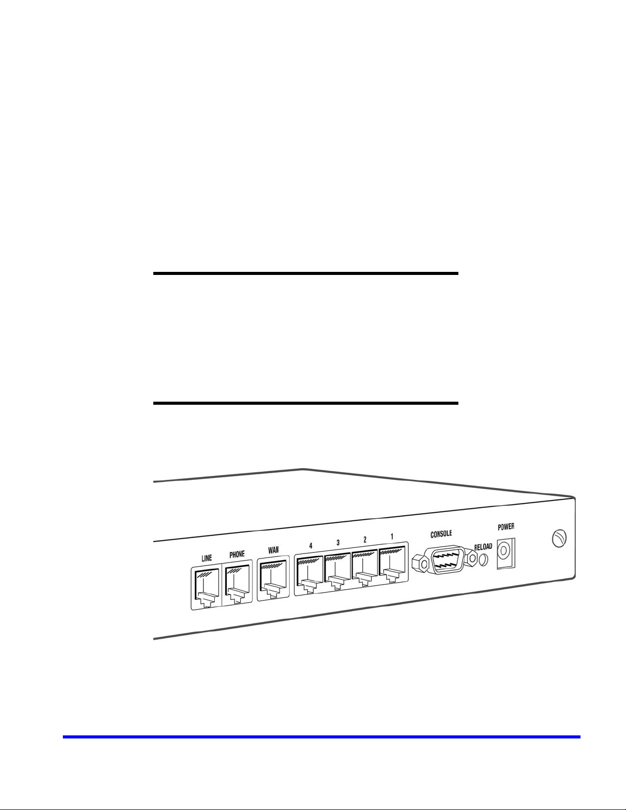
The BSGX4e includes an Foreign Exchange Station (FXS) port that can provide an
analog device with access to VoIP service.
D
EVICE
The BSGX4e includes an Foreign Exchange Office (FXO) port that can provide
backup access to the Public Switched Telephone Network (PSTN).
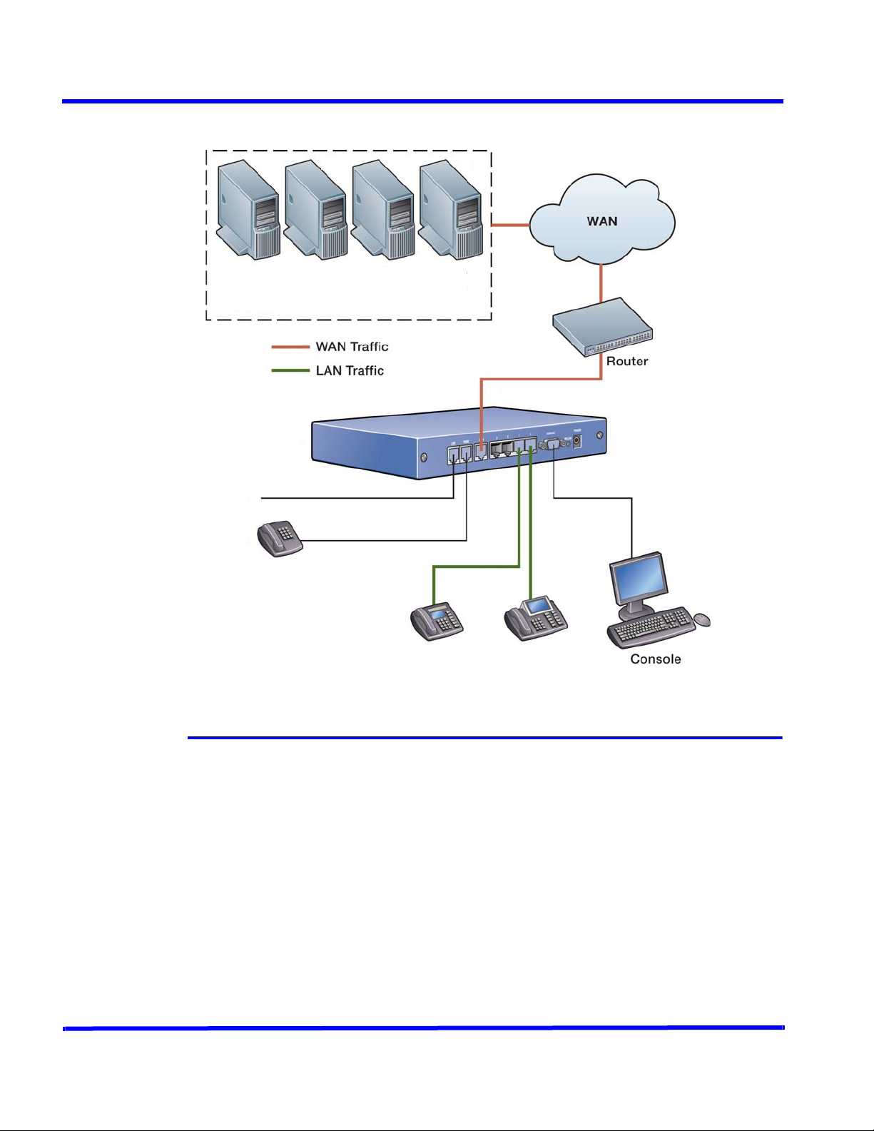
Network Role
Figure 1 shows a possible IP network layout with an BSGX4e unit that connects a LAN
to the WAN. The figure illustrates the following:
The BSGX4e unit can reference servers on the WAN for the devices on its LAN.
LAN devices can include VoIP phones using SIP or MGCP protocols.
Through its FXO port, you can connect the BSGX4e device to a CO line (PSTN) that
acts as a lifeline if VoIP service is not available.
The unit can provide a VoIP connection for an analog device (such as a phone or
fax machine).
Use a console to locally configure and monitor the unit.
Page 30
Administrative
Servers
VoIP Call
Servers
ICAD40
Central Office
Line
Analog Phone
Figure 1. BSGX4e Connectivity
VoIP Phones
Device Features
An BSGX4e unit provides the following services:
VoIP Session Controller
The BSGX4e unit acts as the session controller for up to 1000 VoIP phones. It can
use the SIP or MGCP protocol and can control up to 500 concurrent calls.
When the WAN is down, the unit provides VoIP survivability. It can place calls
between LAN endpoints and, with its intelligent lifeline, it can switch calls to the
PSTN through the emergency backup FXO line.
Integrated VoIP Gateway (User Agent)
An BSGX4e unit also acts as User Agent (UA) for VoIP phones. It provides a VoIP
endpoint within the network, performing signaling, media control, and conversion
from traditional interfaces to VoIP.
30 BSGX4e Business Gateway User Guide
NN47928-102 Release 01.01
Page 31

Connecting to the Device
An BSGX4e unit provides two telephony interfaces: one FXS port for connectivity
of analog phones or fax machines and one FXO port to act as a backup lifeline to
the PSTN.
Security
To provide network security, an BSGX4e unit includes a firewall, an advanced
Intrusion Detection System (IDS), Application Layer Gateway (ALG), and support
for network address translation (NAT) and virtual private networks (VPNs).
Multi-Service QoS
The BSGX4e unit includes an advanced QoS mechanism called Guarantee of
Service (GoS). This easy-to-configure mechanism ensures the optimal priority and
bandwidth allocation for multiple classes of critical traffic. It is compatible with
DiffServ with support for Terms of Service (ToS) field remarking.
LAN Switch
An BSGX4e unit includes a 4-port switch, with support for Layer 2 QoS and VLAN
segmenting.
Monitoring
An BSGX4e unit dynamically monitors and provides statistics for both data and
voice flows (such as Mean Opinion Score (MOS) scores gathered per call).
Management
Perform configuration and monitoring by entering commands or by selecting
options from a Web browser interface. The management system assures secure
remote access with SSH and Hypertext Transfer P rotoc ol over Secure Sock et Layer
(HTTPS).
BSGX4e Business Gateway User Guide 31
Release 01.01 NN47928-102
Page 32

Connecting to the Unit
This user guide assumes that the BSGX4e unit is installed in a working IP network.
The installation procedures are described in the BSGX4e Business Gateway
Installation Guide.
Configure and monitor this unit by using commands or by using its Web user
interface. This user guide describes command use; the Web user interface is
introduced in “Web User Interface” (page 379).
The “Remote Administration Services” (page 33) describes the servers that can
provide remote access to the BSGX4e unit. Remote access requires the IP address of
the unit. If the IP address is unknown, you can determine the IP address during a
console session as described in the following section.
Finding an IP Address using a Console Session
This procedure assumes the following:
A workstation is connected to the CONSOLE port of the BSGX4e through a serial
port cable.
The workstation is running Tera Term Pro or a similar terminal emulator.
Note: This procedure uses Tera Term Pro (see “Third Party Software” (page
399)).
1.Connect to the BSGX4e through the terminal emulator:
a Select File, and then, New Connection from the menu bar.
A window opens titled Tera Term: New Connection.
b Select the Serial button.
c Select the appropriate COM Port.
d Click OK.
Figure 2. Connect to the Console Port
2. Enter a user name, such as nnadmin, after the prompt:
User:
32 BSGX4e Business Gateway User Guide
NN47928-102 Release 01.01
Page 33

Connecting to the Device
3. Enter the password for the user account.
Password:
The initial password is PlsChgMe!; it may have been changed during
installation.
4.System information is displayed, ending with the command prompt that ends
with the greater than (>) symbol.
5. After the command prompt, enter the following command:
> show interface ip
A display similar to the following appears:
"eth0" info:
Interface eth0
Flags (A843) < UP BROADCAST RUNNING SIMPLEX LINKUP MULTICAST
IP Address/Mask 172.16.1.217/255.255.255.0
MTU 1500
DHCP off
Lease obtained N/A
Lease expires N/A
MAC Address 00:15:93:FF:00:F8
Speed FULL100
Configured speed AUTONEG
"eth1" info:
Interface eth1
Flags (A843) < UP BROADCAST RUNNING SIMPLEX LINKUP MULTICAST
IP Address/Mask 192.168.1.1/255.255.255.0
MTU 1500
DHCP off
Lease obtained N/A
Lease expires N/A
MAC Address 00:15:93:FF:00:F9
Speed N/A
Configured Speed N/A
6.Find the IP address on the IP Address/Mask line for the interface to be used:
If connecting to the BSGX4e through the WAN, use the eth0 address.
If connecting to the BSGX4e through a LAN port, use the eth1 address.
Remote Administration Services
This section describes how to configure servers that allow for remote administration
of the BSGX4e unit. These servers are:
Telnet server
Secure Shell (SSH) server
Web server
Secure Socket Layer (SSL) server
BSGX4e Business Gateway User Guide 33
Release 01.01 NN47928-102
Page 34

The Telnet server in the unit is initially disabled, you must open a connection to the
unit from a Telnet session on a workstation. For more information, see “Telnet
Access” (page 34).
The SSH server in the unit is also initially enabled. It provides a means of secure,
remote access. For more information, see “SSH Server” (page 36).
The Web server is initially enabled to allow the use of the Web user interface.
Access to the Web server is described in “Web Server” (page 38).
Show Remote Connections
The maintenance command whoison shows the users that are currently using
remote access to the unit. An example follows:
> whoison
User Source IP Type
-----------------------------------------------------------admin Unknown Terminal
user 10.0.1.2 Web
The Type field indicates how the user is connected to the unit: Terminal (console
port), SSH, Telnet, or Web.
Telnet Access
Telnet allows access to the BSGX4e unit through a remote terminal session. Telnet
access requires the following:
The workstation on the WAN or LAN must provide a Telnet client (for example,
Tera Term Pro, Windows telnet client, or Linux telnet client).
As initially configured, the Telnet server in the unit is enabled, and the firewall
allows Telnet access from the WAN.
If the initial unit configuration is changed, the following reconfiguration can be
required:
For Telnet access from the WAN, the firewall must allow Telnet traffic
terminating at the BSGX4e device. This requires a security policy for TCP traffic
to the Telnet port (The default Telnet port is port 23). For more information
about security policies, see “Firewall Security Policies” (page 130).
The Telnet server on the unit must be configured and enabled as described in the
following section “Telnet Configuration Command” (page 34).
Telnet Configuration Command
To change the Telnet configuration, enter the following command:
> config service telnet
Table 3 describes the parameters for config service telnet.
34 BSGX4e Business Gateway User Guide
NN47928-102 Release 01.01
Page 35

Connecting to the Device
Table 3. Telnet Server Configuration Parameters
Parameter Description
enabled Enables the Telnet server (Boolean). Initially, Telnet is
enabled.
port Telnet server port number. The default is 23.
Telnet Configuration Example
The following example disables the Telnet server on port 23.
> config service telnet no enabled
*> save
Show Telnet Configuration
To verify the Telnet configuration, enter the following command:
> show service telnet
Telnet Service:
Enabled no
Port 23
Telnet Client Command
To start a Telnet session, enter the following command:
> telnet
Table 4 describes the parameters for the maintenance command telnet.
Table 4. Telnet Parameters
Parameter Description
ip address IP address of the BSGX4e device.
-p Optional Telnet port number.
Telnet Session Example
The following example starts a Telnet session on the device at IP address
192.168.134.217:
> telnet 192.168.134.217
Trying 192.168.134.217
Connected to 192.168.134.217
Escape character is '^]'.
User:
BSGX4e Business Gateway User Guide 35
Release 01.01 NN47928-102
Page 36

SSH Server
This section describes how to configure the Secure Shell (SSH) server. The SSH server
enables secure remote access to the BSGX4e device over an insecure network, such
as the Internet. SSH version 2 is supported.
SSH use requires the following:
The workstation on the WAN or LAN must provide an SSH client (for example,
PuTTY or SSH secure shell).
As initially configured, the SSH server in the unit is enabled, and the firewall
allows SSH access from the WAN.
If the initial unit configuration is changed, the following reconfiguration can be
required:
For SSH access from the WAN, the firewall must allow SSH traffic terminating at
the BSGX4e device. This requires a security policy for TCP traffic to the SSH port.
(The default SSH port is port 22). For more information about security policies,
see “Firewall Security Policies” (page 130).
The SSH server on the unit must be configured and enabled as described in the
section “SSH Configuration Command” (page 36).
Digital Signature Algorithm (DSA) Host Keys
The SSH server uses a set of 640-bit DSA host keys (one public, one private) for data
encryption. It stores one set of keys on the file system (/cf0sys/ssh). A randomly
seeded algorithm generates an initial set of host keys the first time that the BSGX4e
device is started. The SSH server uses this set of host keys to identify itself when an
SSH client connects. Regenerate new host keys by using the parameter hostkeys on
the config service ssh command.
After a secure connection is established between the SSH server and a client, the
client attempts authentication. The SSH server supports password, keyboard, and
publickey authentication.
When both password and keyboard authentication are requested, the user
must supply a username and password.
To use publickey authentication, upload files containing the public key of the
SSH client must be to the device in the directory:
/cf0sys/id_<username>.pub.
After the SSH client is authenticated, it requests an SSH secure remote log on.
SSH Configuration Command
To change the SSH configuration, enter the following command:
> config service ssh
Table 5 describes the parameters for config service ssh.
36 BSGX4e Business Gateway User Guide
NN47928-102 Release 01.01
Page 37

Connecting to the Device
Table 5. SSH Configuration Parameters
Parameter Description
enabled Enables the SSH server (Boolean). The initial setting is
enabled.
port SSH server port number. The default is 22.
hostkeys Host keys that the SSH server uses to authenticate itself (none
| 640bit). The default is 640bit.
To regenerate the SSH keys, set HostKeys to none, and then
to 640bit.
authmethods Permitted authentication methods (all | keyboard | password
| publickey | none). The default is all.
services Permitted SSH services (all | ssh | sftp | none). The default is
all.
SSH Example
The following example disables SSH service.
> config service ssh no enabled
*> save
Show SSH Configuration
To verify the configuration, enter the following command:
> show service ssh
SSH Service:
Enabled yes
Port 22
HostKeys 640bit
AuthMethods keyboard + password + publickey
Services ssh + sftp
Regenerate SSH keys
To regenerate the SSH keys, set the parameter HostKeys to none, and then to
640bit. An example follows:
> config service ssh hostkeys none
*> config service ssh hostkeys 640bit
*> show service ssh
SSH Service:
Enabled yes
Port 22
BSGX4e Business Gateway User Guide 37
Release 01.01 NN47928-102
Page 38

HostKeys generating...
AuthMethods keyboard + password + publickey
Services ssh + sftp
The key regeneration can take several seconds. During this period, the value of the
parameter HostKeys is generating....
Upload Public Key
To upload the public key of an SSH client, use a Simple File T r ansfer Protocol (SFTP)
session.
The following example uploads the key of client fred to the BSGX4e device, IP
address 192.168.134.217.
1.Start the SFTP session:
fred@cygnus ~ $ sftp admin@192.168.134.217
Connecting to 192.168.134.217...
The authenticity of host '192.168.134.217 (192.168.134.217)'
can't be established.
DSA key fingerprint is
9a:1f:34:52:f1:78:d7:6c:56:5b:9d:73:f0:da:1f:c0.
Are you sure you want to continue connecting (yes/no)? yes
Warning: Permanently added '192.168.134.217' (DSA) to the
list of known hosts.
User: nnadmin
Password:
sftp> cd /cf0sys
sftp> put id_fred.pub
Uploading id_fred.pub to /cf0sys/id_fred.pub
2.To view the contents of the directory, enter the following command:
sftp> ls
flash id_fred.pub ssh ssl
Web Server
This section describes how to configure the Web server. The Web server enables the
remote administration of the BSGX4e device using the W eb User Interface (see “Web
User Interface” (page 379)).
The Web server supports access through Hypertext Transfer Protocol (HTTP) and
HTTPS (HTTP over SSL). For more information on SSL configuration, see “SSL” (page
40).
Web server use requires the following:
38 BSGX4e Business Gateway User Guide
NN47928-102 Release 01.01
Page 39

Connecting to the Device
The workstation on the WAN or LAN must provide a Web browser (Microsoft
Internet Explorer or Mozilla Firefox).
As initially configured, the Web server in the unit is enabled, and the firewall
allows HTTP or HTTPS traffic from the W AN terminating at the BSGX4e.
NOTE: The initial unit configuration enables the Web server and configures a
security policy to allow Web access from the WAN to the unit.
If the initial unit configuration is changed, the following reconfiguration can be
required:
For Web access from the WAN to the unit, the firewall must allow Web traffic
terminating at the BSGX4e device. This requires access for TCP traffic to the Web
and Web User Interface (UI) ports. (The default Web UI port is port 443; the
default Web port is 80.) For more information about the firewall, see “Firewall
Security Policies” (page 130).
Configure and enable the Web server in the unit as described in the following
section “Web Server Configuration Command” (page 39).
Web Server Configuration Command
To change the Web server configuration, enter the following command:
> config service web
Table 6 describes the parameters for config service web.
Table 6. Web Server Configuration Parameters
Parameter Description
enabled Enables the Web server (Boolean). Initially, the Web server is
enabled.
httpport HTTP port number for the Web server. The default is 80.
httpsport HTTPS port address for the Web server. The default is 443.
Disable Web Server Example
The following example disables the Web server.
> config service web no enabled
*> save
Show Web Server Configuration
To verify the configuration, enter the following command:
> show service web
Web Server:
Enabled yes
BSGX4e Business Gateway User Guide 39
Release 01.01 NN47928-102
Page 40

HTTP Port 80
HTTPS Port 443
Show Web Server Statistics
To display the statistics of the Web server, enter the following command:
> stats service web
Web Stats:
Redirects 0 Errors 0
Access Err 0 Timeouts 0
Form Hits 0 Local Hits 0
Table 7 describes the Web server statistics.
Table 7. Web Server Statistics
Statistic Description
Redirects Number of redirections from the Web server.
Errors Number of Web server errors.
Access Err Number of security violations from the Web server.
Timeouts Number of timeouts from the Web server.
Form Hits Number of form requests.
Local Hits Number of local hits for access.
SSL
This section describes how to configure the Secure Socket Layer (SSL). SSL enables
secure remote access to the BSGX4e device over an insecure network, such as the
Internet.
The steps required to configure SSL are:
1.Generate a new SSL key if the existing key has been deleted or compromised.
2.Generate a new SSL certificate signing request (CSR).
3.Generate or import the SSL certificate.
SSL Key
The system administrator can use the SSL key to manage a private Rivest Shamir
Adleman (RSA) key, which the SSL server requires to encrypt data. The first time the
BSGX4e device is started, a randomly-seeded, 1024-bit RSA key is generated and
saved. Normally, a new private key does not need to be generated unless the
security of the private key has been compromised. The RSA key is stored in the file
/cf0sys/ssl/rsakey.dat.
40 BSGX4e Business Gateway User Guide
NN47928-102 Release 01.01
Page 41

Connecting to the Device
NOTE: If the SSL key is deleted, new SSL connections cannot be created. To see
the status of the SSL key, enter show ssl key.
A new SSL key can be generated. The number of bits is constrained to 512, 768,
1024, or 2048. When the SSL key record is created or modified, a key generation task
is started. Key generation can take several minutes, depending on the size of the
key. When key generation starts, the key used by the SSL server is deleted; new SSL
connections cannot be created until a new key is available. When key generation
completes, the RSA key used by the SSL server is set to the newly generated key;
new SSL connections can then be created.
SSL Key Command
To generate a new SSL key, enter the following command:
> config ssl key
Table 8 describes the parameters for config ssl key.
Table 8. SSL Key Configuration Parameters
Parameter Description
[type] Type of encryption key (RSA).
bits Number of bits in key (512 | 768 | 1024 | 2048).
SSL CSR
A system administrator can use the SSL Certificate Signing R equest (CSR) to generate
an X509 certificate, which can be self-signed by the SSL module or signed by an
external certificate authority (CA).
A single X509 CSR can be generated. Generating a CSR requires an SSL key. To see
the status of the SSL key, enter show ssl key.
NOTE: If the SSL CSR is deleted, new SSL connections cannot be created.
SSL CSR Command
To generate an SSL CSR, enter the following command:
> config ssl csr
Table 9 describes the parameters for config ssl csr.
Table 9. SSL CSR Configuration Parameters
Parameter Description
[type] Certificate signing request type (x509).
country Two-letter country code. The default is US for the United
States; to see the most recent list, go to www.iso.org
state Full name of state or province (such as, California).
BSGX4e Business Gateway User Guide 41
Release 01.01 NN47928-102
Page 42

Table 9. SSL CSR Configuration Parameters (continued)
Parameter Description
locality Locality or city name (such as, Fremont).
orgname Company name (such as, NewCo).
orgunit Organizational unit (such as, Engineering).
commonname Domain name (such as, www.example.com).
email E-mail address (such as, webadmin@example.com).
Upload SSL CSR
Use SFTP to upload an SSL CSR. The recommended directory for the uploaded CSR
file is /cf0sys/ssl. An example follows.
1.Upload the SSL CSR file:
fred@cygnus ~ $ sftp admin@192.168.134.217
Connecting to 192.168.134.217...
The authenticity of host '192.168.134.217 (192.168.134.217)'
can't be established.
DSA key fingerprint is
9a:1f:34:52:f1:78:d7:6c:56:5b:9d:73:f0:da:1f:c0.
Are you sure you want to continue connecting (yes/no)? yes
Warning: Permanently added '192.168.134.217' (DSA) to the
list of known hosts.
User: nnadmin
Password:
2.Set the current directory and store the CSR file in it:
sftp> cd /cf0sys/ssl
sftp> put csr.pem
Uploading csr.pem to /cf0sys/ssl/csr.pem
3.Ensure that the CSR file is in the current directory:
sftp> ls
rsakey.dat csr.pem
At this point, use the imported CSR to generate the SSL certificate as described in
the next section “SSL Certificate” (page 42).
> config ssl certificate x509 import /cf0sys/ssl/csr.pem
*> save
SSL Certificate
A system administrator can use the SSL certificate to configure an X509 certificate
used by the SSL server. Two methods exist to configure the X509 certificate: either
the SSL CSR record is self-signed, or the SSL CSR is signed by an external certificate
authority and an X509 certificate is imported into the SSL certificate.
42 BSGX4e Business Gateway User Guide
NN47928-102 Release 01.01
Page 43

Connecting to the Device
A single X509 certificate can be generated. When self-signed, the certificate is
derived from the current CSR record and key record.
NOTE: A self-signed certificate can be generated only i f an SSL key record and an
SSL CSR record exist.
Alternately, you can import an SSL certificate using a file containing a certificate
signed by an external certificate authority (CA). The certificate must be in Privacy
Enhanced Mail (PEM) format with no header before the “----- BEGIN CERTIFICATE
-----” text. When a CA-signed certificate is imported, the certificate is checked to
ensure that it is in the correct PEM format. If the format is incorrect, the certificate
is not imported.
NOTE: If the SSL certificate is deleted, new SSL connections cannot be created.
SSL Certificate Command
To generate the SSL certificate, enter the following command:
> config ssl certificate
Table 10 describes the parameters for config ssl certificate.
Table 10. SSL Certificate Configuration Parameters
Parameter Description
[type] Certificate type (x509).
signed Self-signs the current CSR (self | null).
import PEM format file from which to import the certificate.
SSL Configuration Example
This example generates an RSA key of 768 bits. It then generates an SSL CSR for the
Sells unit of the company EiffelGroup in Paris, France. Finally it generates a
self-signed SSL certificate.
> config ssl key rsa bits 768
*> config ssl csr x509 country FR no state locality Paris
orgname EiffelGroup orgunit Sells commonname
www.eiffelgroup.com email contact@eiffelgroup.com
*> config ssl certificate x509 signed self
*> save
Show SSL Configuration
To verify the SSL configuration, enter the following commands:
> show ssl key
SSL Key:
Type rsa
BSGX4e Business Gateway User Guide 43
Release 01.01 NN47928-102
Page 44

Bits 768
Status ok
(While key generation occurs, the Status field displays generating…. After key
generation is complete, it displays ok.)
> show ssl csr
SSL Certificate Signing Request:
Type x509
Country FR
State
Locality Paris
OrgName EiffelGroup
OrgUnit Sells
CommonName www.eiffelgroup.com
Email contact@eiffelgroup.com
Status ok
PEMData
MIIBkDCCARkCAQAwgZQxCzAJBgNVBAYTAkZSMQkwBwYDVQQIEwAxDjAMBgNVBAcTB
VBhcmlzMRQwEgYDVQQKEwtFaWZmZWxHcm91cDEOMAwGA1UECxMFU2VsbHMxHDAaBg
NVBAMTE3d3dy5laWZmZWxncm91cC5jb20xJjAkBgkqhkiG9w0BCQEWF2NvbnRhY3R
AZWlmZmVsZ3JvdXAuY29tMHswDQYJKoZIhvcNAQEBBQADagAwZwJgQKmzUXzjbaLl
QXybKsRNTp7+MmMR2vBODvLCqRgLi78AdXkZV2Yy0xfWqTGPRJ1sVOdQmXoWA2nus
va+SEClTuoL92Qnx9qI7NbjrWLn02ZHTflaOBdb2npMgIwbjJ3LAgMBAAGgADANBg
kqhkiG9w0BAQQFAAOBYQAnzBtWdcRLKcX8CObgdkM4jcdhm07giSiBT/wcEQNNk5A
WBlMnubSd2pHzADm3eM2tADQZTs88SnkXm/vdaDrGilxOu44I05xBsgPVnPn/0eo9
i/JxqrulQxgeoVADTds=
-----END CERTIFICATE REQUEST----
-----BEGIN CERTIFICATE REQUEST-----
The Status field shows the status of the CSR, as follows:
no key There is no SSL key.
waiting for The certificate request is being generated.
key generator…
ok Generation is complete; an SSL key is available, and the
PEMData field shows the actual CSR in the standard PEM
format.
> show ssl certificate
SSL Certificate:
Type x509
Country FR
State
Locality Paris
OrgName EiffelGroup
OrgUnit Sells
CommonName www.eiffelgroup.com
Sha1FingerPrint 69 1F 98 DC BC 11 6 D AB 06 5C BF 81 A6 C6
82 EF 7A D6 3A BC
44 BSGX4e Business Gateway User Guide
NN47928-102 Release 01.01
Page 45

Connecting to the Device
Status ok
The Sha1FingerPrint field displays the Secure Hash Algorithm-One (SHA1)
fingerprint of the certificate.
The Status field indicates the status of a self-signed certificate:
no key No SSL key record exists; generate a new key.
no csr No SSL CSR exists; generate a new CSR key.
waiting for The certificate is being generated.
key generator…
ok Certificate generation is complete.
BSGX4e Business Gateway User Guide 45
Release 01.01 NN47928-102
Page 46

46 BSGX4e Business Gateway User Guide
NN47928-102 Release 01.01
Page 47

I
NITIAL
This chapter describes the initial setup of the BSGX4e device, including:
system time and SNTP server configuration
watchdog reset timer
DNS server configuration
default configuration settings
For information about customizing the command line, see “Customizing the
Command Session” (page 78).
S
ETUP
Setting the Time
Two methods exist for setting the system time for the BSGX4e unit.
Acquire the time from the IP network through the SNTP protocol.
Specify up to four SNTP servers.
2
Set the local time manually.
NOTE: If DHCP is enabled and a DHCP server is available, the DHCP server can
provide SNTP server information to the BSGX4e. To see the current SNTP
configuration, enter show system sntp.
Show the Current Time
To display the current time, enter the following command:
> time
FRI NOV 10 8:10:02 2006
Setting the Time Manually
To set the time for the unit, enter the time command specifying the desired time
and date values, as follows:
Specify the time as: -t hh:mm:ss
Specify the date as: -d dd:mm:yyyy
Time Setting Example
To set the time to 2:05 PM on 10 November 2006,enter the following command:
> time -t 14:05:00 -d 10:11:2006
NOTE: The time is changed immediately; you do not need to enter save.
Page 48

Setting the Time through an SNTP Server
The unit can automatically synchronize its internal time to the time provided by an
SNTP server. For automatic time synchronization:
The SNTP client configuration must specify at least one SNTP server and the
appropriate time zone offset.
The SNTP client must be enabled.
NOTE: To change an SNTP server, the SNTP client must be disabled.
SNTP Configuration Command
To configure the SNTP service, enter the following command:
> config system sntp
Table 11 describes the parameters for config system sntp.
Table 11. SNTP Server Configuration Parameters
Parameter Description
enabled Enables the SNTP client (Boolean) To enable, specify enabled. To
disable, specify no enabled. The client is initially disabled.
server1 IP address or Fully Qualified Domain Name (FQDN) of an SNTP server.
server2 IP address or FQDN of an SNTP server.
server3 IP address or FQDN of an SNTP server.
server4 IP address or FQDN of an SNTP server.
gmtoffset Time zone offset from Greenwich Mean Time (GMT) ([+|-]hh:mm,
hours and minutes, positive or negative).
sync Interval for resynchronization of the internal clock to the network
time (external clock) (in days,1—31). The default value is seven.
SNTP Client Example
This example enables the SNTP client and specifies the name of the SNTP server and
the time zone offset.
FQDN of SNTP server : ntpserver.wan.com
GMT offset: one hour forward (+1)
> config system sntp enabled server1 ntpserver.wan.com
gmtoffset +1
*> save
Show SNTP Configuration
To see the SNTP client configuration, enter the following command:
> show system sntp
48 BSGX4e Business Gateway User Guide
NN47928-102 Release 01.01
Page 49

Initial Setup
SNTP:
Enabled on
Server 1 ntpserver.wan.com
Server 2 0.0.0.0
Server 3 0.0.0.0
Server 4 0.0.0.0
Gmt Offset +01:00
Sync Interval 7 days
Last Sync FRI FEB 17 15:53:25 2006
Next Sync FRI FEB 24 15:53:25 2006
Changing SNTP Servers
To change the SNTP servers, disable the SNTP client first. The following command
sequence clears the second SNTP server:
> config system sntp no enabled
*> config system sntp no server2
*> config system sntp enabled
*> save
Watchdog Reset Timer
The watchdog reset timer allows the BSGX4e unit to automatically restart after a
software failure. This timer is required because such a failure could possibly
“freeze” the unit so that no traffic can be routed through it. The automatic reset
allows the unit to recover from that state and restores it to normal operation.
NOTE: It is recommended that the initial watchdog configuration remain
unchanged. The initial configuration enables the reset timer and sets its
value to seven seconds.
Watchdog Timer Command
To configure the watchdog timer, enter the following command:
> config system watchdog
Table 12 describes the parameters for config system watchdog.
Table 12. System Watchdog Configuration Parameters
Parameter Description
enabled Enables the watchdog timer (Boolean). Initially, the timer is enabled.
refresh Refresh interval for the timer (in seconds). The default is seven
seconds.
BSGX4e Business Gateway User Guide 49
Release 01.01 NN47928-102
Page 50

Watchdog Timer Example
The following example enables the watchdog and sets its refresh interval to five
seconds.
> config system watchdog enabled refresh 5
*> save
Show Watchdog Configuration
To show the current watchdog configuration, enter the following command:
> show system watchdog
Watchdog Configuration:
Watchdog Enabled yes
Refresh interval 5 seconds
DNS Client
The Domain Name Service (DNS) client in the unit sends requests to a DNS server on
the WAN. The DNS requests get IP addresses required by the BSGX4e, such as the IP
address of a SIP server specified by FQDN. Two DNS servers can be configured: one
primary, the other as a secondary, backup server.
The DNS client determines the DNS configuration to use based on the current value
of its source parameter:
User: The DNS client uses the latest DNS configuration provided by the user.
DHCP: The DNS client uses the DNS configuration provided by the DHCP server.
PPP: The DNS client uses the DNS configuration provided by the PPP server.
NOTE: The command show system dns shows the DNS configuration currently in
use.
DNS Client Configuration Command
To configure the DNS client, enter the following command:
> config system dns
This command can:
Specify the source of the DNS configuration the client is to use (DHCP, or user).
The default is DHCP.
Specify a user-provided DNS configuration. This configuration is always stored,
but it is used only when the source parameter value is set to user.
Specify an optional domain name that is appended to every DNS request.
Table 13 describes the parameters of config system dns.
50 BSGX4e Business Gateway User Guide
NN47928-102 Release 01.01
Page 51

Initial Setup
Table 13. DNS Client Configuration Parameters
Parameter Description
dns1 IP address of the primary DNS server.
dns2 IP address of an optional, secondary DNS server.
domain Domain name for the unit. For a name that is not an FQDN, the DNS
client adds the domain to the host before querying the DNS server.
Example: If the specified name is host and the specified domain is
domain.com, the query is for host.domain.com.
source Source of the DNS configuration (user | dhcp | ppp). The default is
dhcp.
user Use the latest user-provided configuration.
dhcp Use the configuration provided by the DHCP server . If DHCP
is disabled, dns1 is set to 0.0.0.0 and dns2 and domain
are cleared.
ppp Use the configuration provided by the PPP server. If no PPP
interface is active, dns1 is set to 0.0.0.0 and dns2 and
domain are cleared.
DNS Client Configuration Example
This example shows how the configuration used by the DNS client can change.
1. Assume that DHCP is running and the DNS client uses the default DNS server
configuration provided by the DHCP server.
> show system dns
DNS Settings:
DNS1 172.29.0.1
DNS2 0.0.0.0
Domain wan.com
Source dhcp
2.Enter a fixed, user-provided DNS server configuration. The source parameter is
not changed to user so the new, user-provided configuration is stored, but not
used.
> config system dns dns1 192.168.1.2
> show system dns
DNS Settings:
DNS1 172.29.0.1
DNS2 0.0.0.0
Domain wan.com
Source dhcp
BSGX4e Business Gateway User Guide 51
Release 01.01 NN47928-102
Page 52

3.Change the source parameter to user and the previously entered, user-provided
configuration is used.
> config system dns source user
> show system dns
DNS Settings:
DNS1 192.168.1.2
DNS2 0.0.0.0
Domain
Source user
Show DNS Client Configuration
To see the configuration currently in use by the DNS client, enter the following
command:
> show system dns
DNS Settings:
DNS1 192.168.134.160
DNS2 0.0.0.0
Domain wan.com
Source dhcp
Check DNS Server Accessibility
After the configuration is complete, ensure that the DNS server is accessible. To do
this, ping a device by name. The ping command references the DNS server to
translate the name to an IP address.
In the following example, assume that the domain is configured as wan.com. The
example pings a SIP server on the LAN named sipserver.
> ping sipserver
Pinging sipserver.wan.com (192.168.134.162): 56 data bytes
Reply from 192.168.134.162: bytes=56 icmp_seq=0 time<1ms
Reply from 192.168.134.162: bytes=56 icmp_seq=1 time<1ms
Reply from 192.168.134.162: bytes=56 icmp_seq=2 time=5ms
Reply from 192.168.134.162: bytes=56 icmp_seq=3 time<1ms
----- sipserver.wan.com ping statistics ----4 packets transmitted, 4 packets received, 0.0% packet loss
Round-trip times: min/avg/max=0/0/5ms
Initial Settings
To list the current configuration of the unit, enter a dump command.
52 BSGX4e Business Gateway User Guide
NN47928-102 Release 01.01
Page 53

Initial Setup
Table 14 lists the initial settings of the unit when it is shipped. It also references the
sections in this guide where the settings are discussed.
Table 14. Initial Settings
IP Interface
Initial Settings To change, go to:
eth0 IP address: 0.0.0.0
No IP mask
“eth0 Configuration Command” (page 92)
DHCP client is on (enabled)
eth1 IP address/mask:
192.168.1.1/255.255.255.0
“LAN Interface (eth1)”
(page 102)
DHCP client is off (disabled)
User Groups “User Groups” (page 64)
admins access: ssh + Web + cli + telnet + ftp
All access permissions
users access: Web + cli
User Accounts “User Accounts” (page 61)
admin access ssh + Web + cli + telnet + ftp
group1 admins
group2 users
group3 admins
group4 admins
group5 admins
password admin
user access Web + cli
group2 users
group3 users
group4 users
group5 users
password netcat
User Rights “User Rights” (page 66)
admin access read and write all objects,
including configuration com-
mands
gname admins
object Admins
useradv access read
gname users
object Admins
userbasic access read + write
gname users
object Users
BSGX4e Business Gateway User Guide 53
Release 01.01 NN47928-102
Page 54

Table 14. Initial Settings (continued)
Security Policies
SSH access
from WAN to
unit allowed
Web UI
(HTTPS) access
from WAN to
unit allowed
Web (HTTP)
traffic from
WAN to unit
allowed
Telnet access
from WAN to
unit allowed
Voice
Settings
Media
Settings
Voice ACL
Policies
Traffic from WAN to LAN is rejected.
Traffic from WAN terminating at the
unit is rejected, except for Web UI,
SSH, and Telnet traffic.
Seq 1
From eth0
To self
Destination Port 22
Protocol tcp
Seq 3
From eth0
To self
Destination Port 443
Protocol tcp
Seq 5
From eth0
To self
Destination Port 80
Protocol tcp
Seq 7
From eth0
To self
Destination Port 23
Protocol tcp
jitter buffer type: ADAPTIVE
threshold: 0
gain: Tx -3 Rx -3
Telephony port is set for U.S.A. telephones.
Real-time Transport Protocol (RTP)
13000 - 14999
Default range for source User Datagram
Protocol (UDP) port values of RTP traffic is bridged by the unit.
LAN to LAN communications are bridged
through the unit.
500 calls are allowed.
All LAN SIP or MGCP endpoints are
allowed to originate and receive calls.
Seq 1
Stats 0
“Firewall Security Policies” (page 130)
“FXS Port Configuration”
(page 238)
“Media Bridge (MBR)”
(page 229)
“Access Control List (ACL)”
(page 232)
Layer 2 QoS Disabled. “Layer 2 QoS” (page 106)
Telnet server Enabled. “Telnet Access” (page 34)
54 BSGX4e Business Gateway User Guide
NN47928-102 Release 01.01
Page 55

Table 14. Initial Settings (continued)
Initial Setup
SSH server Enabled.
“SSH Server” (page 36)
AuthMethods: keyboard + password +
publickey
Services: ssh + sftp
Web server Enabled. “Web Server” (page 38)
Logging Audit logging: enabled (show audit log)
Remote module logging (udplog and
syslog): disabled.
“Audit Logging” (page 324)
and “Module Logging”
(page 325).
Local module logging: enabled (show
logging internal)
Watchdog
reset timer
SNTP
client
Enabled. “Watchdog Reset Timer”
(page 49)
Enabled because of DHCP. “Setting the Time through
an SNTP Server” (page 48)
DNS client Enabled because of DHCP. “DNS Client” (page 50)
SNMP Enabled. “SNMP Agent” (page 347)
NAT Enabled on the WAN interface (eth0). “Configuring NAT” (page
134)
ALG Enabled. “ALG Configuration” (page
140)
IDS Enabled. “IDS” (page 140)
DHCP server Enabled. Configured on the eth1 inter-
“DHCP Server” (page 309)
face, when a LAN device requests an IP
address, the server can assign an
address from its address pool
192.168.1.50-192.168.1.250/24.
DHCP relay Disabled. “DHCP Relay” (page 312)
DNS relay Disabled. “DNS Relay” (page 313)
TFTP relay Disabled. “TFTP Relay” (page 316)
SNTP relay Disabled. “SNTP Relay” (page 315)
SIP session
controller
Disabled. “SIP Session Controller”
(page 271)
SIP gateway Disabled. “SIP Gateway” (page 278)
MGCP session
controller
Disabled. “MGCP Session Controller
Configuration” (page 215)
MGCP gateway Disabled. “MGCP Gateway” (page
222)
GoS traffic
protection
Disabled. “GoS Configuration” (page
181)
RIP daemon Disabled. “Starting the RIP Daemon”
(page 126)
BSGX4e Business Gateway User Guide 55
Release 01.01 NN47928-102
Page 56

Table 14. Initial Settings (continued)
VLAN Disabled. “VLAN Configuration”
(page 111)
Netflow agent Disabled. “Netflow Exporter” (page
343)
PMON agent Disabled. “Protocol Monitoring
(PMON)” (page 340)
56 BSGX4e Business Gateway User Guide
NN47928-102 Release 01.01
Page 57

3
U
SER
This chapter describes how to control access to the BSGX4e unit:
password entry
adding and removing users
setting up groups
assigning permission to users and to groups
authentication using a Radius server or a TACACS+ server
IMPORTANT: The security of the BSGX4e unit depends on password security. To
ensure secure access to the unit, change passwords regularly and
keep them secure.
NOTE: To perform user management functions that change the user
management database, you must log on with a user ID that has both read
and write access. The pre-defined user ID nnadmin has all access rights.
M
ANAGEMENT
User Management Features
The user management functions determine who can access the BSGX4e unit and
whether the user can change the configuration of the unit or just display
information stored in it.
User access is controlled both at logon and after log on:
At log on, user access is determined by the user ID and password:
n The user ID determines if the access method is allowed (for example, remote
access can be denied to the user).
n The password must be authenticated (either internally or externally) before
access is allowed.
After log on, the user's access rights limit what the user can do.
You can perform user management functions through a console directly connected to
the unit or remotely by using Telnet or SSH. In both cases, you must log on with a
valid user account. You can also perform user management functions by using the
Command Line Interface (CLI) or the Web user interface (Web UI). For information
about using Web UI, see “Web User Interface” (page 379).
The following is a summary of user management functions:
Requires log on with a valid user ID and password:
Page 58

n Authenticates the entered password by using either strong password hashing
(SHA) or external authentication through a Radius server.
n Never stores passwords in clear text.
Tracks log on attempts:
n Locks out the console port after three failed log on attempts.
n Keeps a log of all failed log on attempts and logouts.
Can limit user accounts to specific access methods, including CLI, Web UI,
Telnet, SSH, and/or File Transfer Protocol (FTP).
Lists who is currently logged in to the system:
n User list includes their access methods and their IP addresses, if any.
n Multiple users can log on simultaneously.
Supports management of users by user groups:
n Users can belong to more than one group.
n Each user management element (user accounts, user groups, and associated
rights records) can be added, edited, and deleted independently.
n Can assign rights to read and/or write access by user account and by user
group.
n Enforces who has access to which modules in the system, using specified
access methods and under what conditions.
Provides an audit log that records:
n Account activities.
n Logins and logouts.
n All failed log on attempts.
Password Entry
All access to the BSGX4e unit requires the entry of a valid user ID and password. The
factory settings for the unit define two user IDs:
nnadmin with initial password PlsChgMe!
user with initial password netcat
The installation procedure recommends that these passwords be changed
immediately.
NOTE: For security reasons, it is recommended that all passwords be changed
on a regular basis.
Failed log on Attempts
A user can attempt to log on from the console port three times. If the user log on
fails all three times, the console is locked out, and no one can log on to the console
port for the next fifteen minutes or until the unit is restarted by a power recycle.
When attempting to log on remotely through Telnet or SSH, the user is given three
log on attempts, and then the session is ended.
58 BSGX4e Business Gateway User Guide
NN47928-102 Release 01.01
Page 59

User Management
All invalid log on attempts are recorded in the audit log. For more information about
the audit log, see “Audit Logging” (page 324).
Changing a Password
Changing a password depends on whether the user account uses internal or external
authentication (as determined by its auth parameter; see “User Accounts” (page
61)) If a user account uses internal authentication, the password for the account can
be changed while logged on to the account.
NOTE: If a user account uses external authentication, the external
authentication server controls the password for the account. Although
the user, while logged on, can change the password stored for the user
account, this password is not used for authentication and so the
effective password is not changed.
NOTE: The administrator (that is, the user logged in with user ID nnadmin) can
change the password used for internal authentication for any user
account. This is done using the config user account command described
on page 61.
While logged on, all users can change their own passwords. To change your
password, use this procedure:
To change the password while logged on, use this procedure:
1. Enter the command password:
> password
2.Enter the old password:
Old Password: ******
3.Enter the new password:
New Password: **********
4.Reenter the new password:
Verify Password: **********
If the new password is reentered correctly, the unit responds with the
following message and the user ID (in this case, nnadmin):
Changed password for 'nnadmin'
5.To save the password change, enter:
*> save
BSGX4e Business Gateway User Guide 59
Release 01.01 NN47928-102
Page 60

Showing Active Users
To see which users are currently logged in to the unit, use the maintenance
command whoison; its display shows the source IP address of the user and the type
of access in effect. An example follows:
> whoison
User Source IP Type
-----------------------------------------------------------admin Unknown Terminal
user 10.0.1.2 Web
The Type field indicates how the user is connected to the unit: Terminal (console
port), SSH, Telnet, or Web.
60 BSGX4e Business Gateway User Guide
NN47928-102 Release 01.01
Page 61

User Management
User Accounts, Groups and Rights
User access to an BSGX4e unit is managed by using user accounts, user groups, and
user rights settings. The initial factory settings for the unit define the following:
Two user groups—one for administrators (admins) and one for other users
(users). The admins user group is granted all access modes, and the other user
group is granted only Web and CLI access.
Two user accounts—one for administrators (admin) and one for other users
(user). The admin user is granted all access modes and all access rights; the
other user account is granted only Web and CLI access, and its access rights are
restricted. The admin account belongs to both predefined user groups (admins
and users); the other user account belongs only to the users user group.
Three rights settings—one for the admins user group and the other two for the
users user group. All rights are granted to admins; the two rights settings for the
users user group grant read-only access to some objects and read and write
access to other objects.
NOTE: You cannot delete or rename the predefined user management
configuration. You cannot delete or rename the two user groups (admins
and users), the two user accounts (admin and user), or the three user
rights settings (admin, useradv, and userbasic).
User Configuration Commands
Table 15 lists the three user configuration commands.
Table 15. Config User Commands
Command Configures:
config user account A user account.
config user groups A user group.
config user rights A rights record (grants to a group read
and/or write access to certain objects).
User Accounts
Before you add a new user account or change an existing user account, display the
current user accounts and user groups by entering the following commands:
> show user accounts
> show user groups
Then, to add or change an account, use the following command:
> config user account
NOTE: The maximum number of user accounts that you can define for the
BSGX4e unit is 20.
BSGX4e Business Gateway User Guide 61
Release 01.01 NN47928-102
Page 62

Table 16 describes the parameters for config user account.
Table 16. User Account Configuration Parameters
Parameter Description
[name] Name of the existing account to be changed or the new account to be
added. This parameter is required.
If an existing account is specified, only the specified parameter
values are changed; all other existing values remain unchanged.
access Access methods allowed to this user. The default is none.
all All access methods allowed.
none No access allowed.
You can specify that two or more of the following methods are to be
connected by using plus (+) symbols.
ssh Secure Shell (SSH) access allowed.
Web Web User Interface (Web UI) access allowed.
cli Command Line Interface (CLI) access allowed.
telnet Remote access through a Telnet session allowed.
ftp File Transfer Protocol (FTP) access allowed.
auth Internal or external password authentication. The default is internal
Strong Password Hashing (SHA).
To require external authentication, specify RADIUS or TACACS and
configure an authentication record for this user account. Fore more
information , see “Radius Authentication” (page 68).
group1 Required first group to which the user belongs. A user must belong to
at least one group and can belong to up to five user groups. The
predefined user groups are admins and users. If another user group is
configured, you can assign the user account to that group.
To remove the user from a group, specify the group parameter with
the value none.
group2
Optional additional user groups to which the user account is assigned.
group3
group4
group5
password The password assigned to the user. This parameter is required.
The password for the user account. Entry of this parameter is
required at logon if internal authentication is used. (If external
authentication is used, the password entered at logon must be the
one defined by the external server.)
inherit Whether the user account inherits access rights from the groups to
which it belongs. The default is yes.
enabled Whether the user account is enabled. The default value is yes.
62 BSGX4e Business Gateway User Guide
NN47928-102 Release 01.01
Page 63

User Management
Add User Account Example
This example assumes that the user is given read and write access to the unit, but
only while connected directly to its console port or to the W eb interface—no remote
access is allowed:
name of user account: user1
access methods allowed: Web + cli
group membership: admins
assigned password: test123
NOTE: This example is shown in interactive mode. For more information, see
“Interactive Mode” (page 82).
Enter the following commands:
> config user account user1
Entering interactive mode: ctrl^z | 'exit', ctrl^c | 'quit'
TAB to cycle parameter options
user-accounts-user#> access web + cli
user-accounts-user#> group1 admins password test123
user-accounts-user#> exit
*> save
Show User Account
To show the settings for account user1, enter the following command:
> show user account user1
The display is similar to the following:
Users:
Name Access Auth Group1 Group3 Group5 Password
Inherit Group2 Group4 Enabled
------------------------------------------------------------user1 web + cli SHA admins ******
yes yes
Note: Every password is encrypted, so the Password field can only show
asterisks.
Deleting a User Account
To delete a user account, specify the name of the account on the command delete
user account.
NOTE: You cannot remove or rename the predefined user accounts admin and
user.
For example, to delete a user account named user1, enter the following commands:
BSGX4e Business Gateway User Guide 63
Release 01.01 NN47928-102
Page 64

> del user account user1
*> save
User Groups
Before you add a new user group or change an existing user group, review the
settings of the current user groups by entering the following command:
> show user groups
Then, to add or change a group, use the following command:
> config user group
NOTE: The maximum number of user groups that you can define for the BSGX4e
unit is 10.
Table 17 describes the parameters for config user group.
Table 17. User Group Configuration Parameters
Parameter Description
[name] Name of the user group to be added or the existing user group
to be changed. This parameter is required.
If an existing user group is specified, only the specified
parameter values are changed; all other existing values for the
group remain unchanged.
access Access methods allowed to user accounts in this group. The
default is none.
NOTE: A user account uses this access value only if its own
access value is none and the access values of any
preceding groups in its group list are also none.
all All access methods allowed.
none No access allowed.
You can specify that two or more of the following methods are
to be connected by using plus (+) symbols.
ssh Secure Shell (SSH) access allowed.
Web Web User Interface (Web UI) access allowed.
cli Command Line Interface (CLI) access allowed.
telnet Remote access through a Telnet session allowed.
ftp File Transfer Protocol (FTP) access allowed.
64 BSGX4e Business Gateway User Guide
NN47928-102 Release 01.01
Page 65

User Management
Table 17. User Group Configuration Parameters (continued)
Parameter Description
auth Internal or external password authentication. The default is
internal Strong Password Hashing (SHA).
To require external authentication, specify RADIUS or TACACS
and configure an authentication record for this user account.
For more information, see “Radius Authentication” (page 68).
all Indicates whether all access is given to the group. The default
is no, meaning that enforcement is in place to check the
access rights of the users in the group. If yes is specified for a
group (such as for the admins group), access checks are not
enforced.
Add User Group Example
This example adds a new user group as follows:
name: dev
access: all (ssh, web, cli, telnet, ftp)
all access: yes (allowed)
To add the new group, enter the following commands:
> config user group dev access all all yes
*> save
Show a User Group
To show the settings for group dev, enter the following command:
> show user group dev
The display is similar to the following:
Groups:
Name Access Authorization
Allow All
------------------------------------------------------------dev ssh + web + cli + telnet + ftp SHA
yes
Deleting a User Group
To delete a user group, specify the name of the group by using the command delete
user group.
NOTE: You cannot delete the predefined user groups named users and admins.
For example, to delete a user group named dev, enter the following commands:
> del user group dev
*> save
BSGX4e Business Gateway User Guide 65
Release 01.01 NN47928-102
Page 66

User Rights
This section describes how to configure a record that defines the access of a group
to certain objects. The available access rights are read, write, and execute. Read
allows the viewing of data; write allows the writing of data; execute is not currently
used.
A group can have more than one rights record defined for it. For example, the
predefined rights records useradv and userbasic are both defined for the same user
group: the user group users. In this case, two rights records are defined so that the
user group can be granted different access to different objects in the system, as
follows:
The useradv record applies to objects that belong to Admins; it grants only read
access.
The userbasic record applies to objects that belong to Users; it grants both read
and write access.
NOTE: In most cases, the default user rights records should suffice; do not
change them unless the effects of authority and object ownership are
clearly understood.
Command Authority
Commands are objects that belong to either Admins or Users. When you list the
online help for a command (by entering the command followed by a question mark
(?) or tab key), you see a line for Authority, for example:
> ping?
Command: ping
Desc: Ping another device on the network
Authority: Users
If the Authority is Users, the command is an object that belongs to Users, and the
right to use that command is governed by the rights record that grants access to
objects belonging to Users.
In general, commands that require write access, such as config commands, have
Admins authority. Commands that only display data, such as show and stats, have
Users authority. Similarly , maintenance commands that require write access have
Admins authority.
The notable exception is the save command that saves configuration changes; it has
Users authority so it is available to all users belonging to groups admins or users.
Configuration Requirements
You must configure the user group before you can configure a rights record for it.
For more information, see “User Groups” (page 64).
NOTE: In most cases, the default settings provide the appropriate permissions
per user level. It is recommended not to change the settings unless
66 BSGX4e Business Gateway User Guide
NN47928-102 Release 01.01
Page 67

User Management
deemed necessary and only when the effects of authority and object
ownership are clearly understood.
Configuration Command
Before adding a new rights record or changing an existing rights record, review the
current records by entering the following command:
> show user rights
Then, to add or change a rights record, use the following command:
> config user rights
Table 18 describes the parameters for config user rights.
Table 18. User Rights Parameters
Parameter Description
[id] Identifier of the new or existing rights record. This parameter is
required.
If you edit an existing rights record, only the values specified on
this command are changed; all other values in the record remain
unchanged.
access Rights granted by this record.
all Read, write, and execute.
none No rights granted.
You can specify that two or more of the following methods are
to be connected by using plus (+) symbols.
read Read permission.
write Write permission.
execute Execute permission.
gname Name of the user group granted the rights in this record.
object Objects to which this record applies (Admins | Users).
Objects can belong to Admins or to Users. For example, if the
help description for a command lists its Authority as Admins,
then a rights record for Admins determines if the group can use
that command. For more information, see “Command
Authority” (page 66).
Add User Rights Example
This example defines a new rights record. The new record applies to the user group
users; it grants read access to objects belonging to Users, as follows:
id: user (user being configured)
access modes allowed: read
group name: users
object name: Users
BSGX4e Business Gateway User Guide 67
Release 01.01 NN47928-102
Page 68

Enter the following commands:
> config use r rights user access read gname users object Users
*> save
Show User Rights Record
To show the rights record named user, enter the following command:
> show user rights user
The display is similar to the following:
Access Rights:
Identifier Access mode Group name Object name
------------------------------------------------------------user read users Users
Deleting a User Rights Record
To delete a user rights record, specify the name of the record on the command
delete user rights.
NOTE: You cannot rename or delete the predefined rights records named
admin, useradv, and userbasic.
For example, to remove a user rights record named user, enter the following
command:
> del user rights user
*> save
Radius Authentication
To provide additional security for user logins to the BSGX4e device, you can require
an external authentication of passwords. When a password is externally
authenticated, a client in the device sends the password to an external server for
authentication.
The Radius client:
NOTE: When external authentication is used for a user account, the external
server defines the password required for logon using the account. The
password command can change the internal password stored for the
account, but this password is not used for authentication and so the
effective password is not changed.
The Radius client in the BSGX4e device:
is compatible with standard Radius servers
maps Radius authentication records to users by their user account name
can reference up to twenty Radius authentication records
68 BSGX4e Business Gateway User Guide
NN47928-102 Release 01.01
Page 69

User Management
provides legacy authentication, which enables the BSGX4e to function as a
Network Access Server (NAS)
NOTE: The password of a user account is externally authenticated by a Radius
server only if its auth parameter value is Radius. This value can be
specified for the user account or for a user group to which the user
account belongs. User account configuration is described on page 61 and
user group configuration is described on page 64.
Configuration Requirements
For a user account to use Radius authentication, the following requirements must be
met:
1. The authentication (auth) value for the user account must be RADIUS. (User
account configuration is described on page 61.)
2. The Radius client must have an authentication record for the user account.
3. The user account and its password must be defined on the external Radius server.
Configuration Steps
To configure a user account to use Radius authentication, perform these steps:
1. Change the authentication (auth) value for the user account to Radius.
(User account configuration is described in “User Accounts” (page 61))
2. Configure a Radius authentication record for the user account.
3. Configure the user account and its password on the external server.
NOTE: Disabling its authentication record suspends Radius authentication for a
user account. This prevents logons by the user account until either its
authentication record is reenabled or its authentication method (auth
value) is changed.
Radius Authentication Records
After you configure a user account to use Radius authentication, you must configure
a Radius authentication record for that user account. Every user account that uses
Radius password authentication must have its own Radius authentication record.
NOTE: You must configure the user account before you configure the
corresponding Radius authentication record. For more information, see
“User Accounts” (page 61).
Each user account that is to use Radius password authentication must have its own
Radius authentication record. If the same Radius server is referenced by every user
account, the same values are specified in every authentication record.
NOTE: Deleting the user account also deletes its authentication record.
The Radius authentication record specifies:
BSGX4e Business Gateway User Guide 69
Release 01.01 NN47928-102
Page 70

the name or address of the Radius server (authserver)
the secret that the client shares with the server (secret)
how the Radius server accesses the Radius client:
n If DHCP is enabled, specify that the client automatically binds to an interface
(auto yes) and specify the interface (interface).
n If DHCP is disabled, specify the binding IP address of the client (bindaddr).
To configure a Radius authentication record, enter the following command:
> config radius client
Table 19 describes the parameters for config radius client.
Table 19. Radius Authentication Record Parameters
Parameter Description
[user] Name of the user account to which the authentication record
applies. The user account must specify Radius authentication.
enabled Indicates whether the Radius client is enabled for the user. The
default is yes.
auto Indicates whether the client automatically binds to the interface
specified by the interface parameter. Specify yes if DHCP is in use.
The default is no.
authserver FQDN or IP address of the Radius authorization server that the
client references.
secret Shared secret for the client as determined by the server.
bindaddr Binding IP address for the client. It is the IP address of the
interface that the server references (typically, the IP address of
the WAN interface.) Specify this value only if DHCP is not in use.
interface
Physical interface through which Radius communicates if the auto
parameter is yes. This is typically the WAN interface (eth0). To
clear the parameter, specify none.
Example of Configuring a Radius Authentication Record
This example creates an authentication record for user account RadiusUser. It
assumes the following:
The user account RadiusUser is configured and specifies Radius as its
authentication method.
DHCP is in enabled for the unit:
User account name: RadiusUser
FQDN of Radius server: radius.wan.com
Shared secret: Radsecret
Interface that the server references: eth0
1. Enter the following command:
70 BSGX4e Business Gateway User Guide
NN47928-102 Release 01.01
Page 71

User Management
> conf radius client RadiusUser
Entering interactive mode: ctrl^z | 'exit', ctrl^c | 'quit'
TAB to cycle parameter options
radius-cl-user#> enabled yes
radius-cl-user#> auto yes
radius-cl-user#> authserver radius.wan.com
radius-cl-user#> secret Radsecret
radius-cl-user#> interface eth0
radius-cl-user#> exit
2.To save the configuration, enter:
*> save
Show Radius Authentication Records
To list the Radius authentication records, enter:
> show radius client
The following display shows two authentication records: one for user account
RadiusUser and the other for user account RadiusUser2. Both records reference the
same Radius server through the same interface (eth0).
Radius Client:
User Enabled Auth Bind Interface Automatic Secre t
-------------------------------------------------------------------------RadiusUser yes 172.16.1.72 0.0.0.0 eth0 yes Rad secret
RadiusUser2 yes 172.16.1.72 0.0.0.0 eth0 ye s Rad secret
Radius Activity Logs
Radius client activity is reported in the system log.
To see the system log entries, enter the following command:
> show logging internal
The following display shows log entries for a failed Radius authentication:
(E)02:36:31: rc_send_server: bind: radius.wan.com: errno = 0x31
(C)02:36:31: RADIUS Authentication failure
(E)02:36:31: Cannot authenticate Radius!
(C)02:36:31: Cannot initialize Radius user:
(E)02:36:31: Cannot authenticate RADIUS user RadiusUser
(W)02:36:31: RadiusUser INVALID LOGON at TUE MAR 06 02:34:45 2007
RadiusUser
TACACS+ Authentication
To provide additional security for user logins to the BSGX4e device, you can require
external authentication of user logins. When a login is externally authenticated, a
client in the device sends the login information to an external server for
authentication.
BSGX4e Business Gateway User Guide 71
Release 01.01 NN47928-102
Page 72

One external authentication method uses the TACACS+ protocol. This protocol
provides authentication, authorization, and accounting services. Normal operation
fully encrypts the body of the packet for secure communication. It uses TCP port 49.
The TACACS+ client:
Is compatible with standard TACACS+ servers.
Maps TACACS+ authentication records to users by their user account name.
Can reference up to twenty TACACS+ authentication records.
Provides legacy authentication, enabling the BSGX4e to function as a Network
Access Server (NAS).
Configuration Steps
To configure a user account to use TACACS+ authentication, perform these steps:
1. Change the authentication (auth) value for the user account to TACACS+. This
value can be specified for the user account or for a user group to which the user
account belongs. (User account configuration is described in “User Accounts”
(page 61) and user group configuration is described in “User Groups” (page 64).)
2. Configure a TACACS+ authentication record for the user account.
NOTE: Disabling its authentication record suspends TACACS+ authentication
for a user account. This prevents logins by the user account until either
its authentication record is re-enabled or its authentication method
(auth) is changed.
TACACS+ Authentication Records
After a user account is configured to use TACACS+ authentication, a TACACS+
authentication record must be configured for that user account.
NOTE: The user account must be configured before the corresponding TACACS+
authentication record is configured (see “User Accounts” (page 61)).
Each user account that is to use T ACACS+ password authentication must have its own
TACACS+ authentication record. If the same TACACS+ server is referenced by every
user account, the same values are specified in every authentication record.
The TACACS+ authentication record specifies:
the name or address of the TACACS+ server (server).
the key that the client shares with the server (key).
To configure a TACACS+ authentication record, enter the command:
> config tacplus client
Table 19 describes the parameters for config tacplus client.
72 BSGX4e Business Gateway User Guide
NN47928-102 Release 01.01
Page 73

User Management
Table 20. TACACS+ Authentication Record Parameters
Parameter Description
[user] Name of the user account to which the authentication record
applies. The user account must specify TACACS+ authentication.
enabled Whether the TACACS+ client is enabled for the user. The default is
yes.
server IP address of the TACACS+ server that the client references.
key Shared key for the client as determined by the server.
Example of Configuring a TACACS+ Authentication Record
This example creates an authentication record for user account TACuser. It assumes
that the user account TACuser has been configured and TACACS+ has been specified
as its authentication method.
User account name: TACuser
IP address of TACACS+ server: 172.16.249.52
Shared key: tacacskey
Enter these commands:
> config tacplus client TACuser
Entering interactive mode: ctrl^z | 'exit', ctrl^c | 'quit'
TAB to cycle parameter options
tacplus-cl-user#> enabled yes
tacplus-cl-user#> server 172.16.249.52
tacplus-cl-user#> key tacacskey
tacplus-cl-user#> exit
*> save
Show TACACS+ Authentication Records
To list the TACACS+ authentication records, enter:
> show tacplus client
The following display shows two authentication records, one for user account
TACuser and the other for user account root. Both records reference the same
TACACS+ server.
TACACS+ Client:
User Enabled Server Key
------------------------------------------------------------TACuser yes 172.16.249.52 tacacskey
root yes 172.16.249.52 tacacskey
BSGX4e Business Gateway User Guide 73
Release 01.01 NN47928-102
Page 74

TACACS+ Activity Logs
TACACS+ client activity is reported in the system log. Log entries indicate whether
authentication attempts are successful or not.
To see the system log entries, enter the following command:
> show logging internal
The following display shows log entries for a failed TACACS+ authentication:
(I)22:16:24: User root is attempting to logon at THU FEB 08 22:16:24 2007
(I)22:16:24: Verify TACACS+ user root at THU FEB 08 22:16:24 2007
(I)22:16:24: User root cannot be found
(C)22:16:24: Cannot authenticate Tacacs+ user: root
(W)22:16:24: root INVALID LOGON at THU FEB 08 22:16:24 2007
TACACS+ Authentication
To provide additional security for user logins to the BSGX4e device, you can require
external authentication of user logins. When a login is externally authenticated, a
client in the device sends the login information to an external server for
authentication.
NOTE: When external authentication is used for a user account, the external
server defines the password required for logon using the account. The
password command can change the internal password stored for the
account, but this password is not used for authentication and so the
effective password is not changed.
One external authentication method uses the TACACS+ protocol to provide
authentication services. Normal operation fully encrypts the body of the packet for
secure communication. It uses TCP port 49.
The TACACS+ client in the BSGX4e device:
Is compatible with standard TACACS+ servers.
Maps TACACS+ authentication records to users by their user account name.
Can reference up to twenty TACACS+ authentication records.
Provides ASCII login authentication, enabling the BSGX4e to function as a Network
Access Server (NAS).
Configuration Requirements
For a user account to use TACACS+ authentication, the following requirements must
be met:
1. The authentication (auth) value for the user account must be TACACS+. (User
account configuration is described on page 61.)
2. The TACACS+ client must have an authentication record for the user account.
74 BSGX4e Business Gateway User Guide
NN47928-102 Release 01.01
Page 75

User Management
3. The user account and its password must be defined on the external TACACS+
server.
NOTE: Disabling its authentication record suspends TACACS+ authentication
for a user account. This prevents logins by the user account until either
its authentication record is re-enabled or its aut h entication method
(auth value) is changed.
TACACS+ Authentication Records
For each user account configured to use TACACS+ authentication, a TACACS+
authentication record must be configured. The authentication record for a user
account serves two purposes:
It specifies the TACACS+ server that authenticates the account by providing:
n the name or address of the TACACS+ server (server).
n the key that the client shares with the server (key).
It enables or disables TACACS+ authentication for the account.
NOTE: Deleting the user account also deletes its authentication record.
Every authentication record that references the same TACACS+ server specifies the
same server and key values.
To configure a TACACS+ authentication record, enter the command:
> config tacplus client
Table 21 describes the parameters for config tacplus client.
Table 21. TACACS+ Authentication Record Parameters
Parameter Description
[user] Name of the user account to which the authentication record
applies. To use the authentication record, the user account must
specify TACACS+ authentication.
enabled Whether the TACACS+ client is enabled for the user. The default is
no.
server IP address or FQDN of the TACACS+ server that the client
references.
key Shared key for the client as determined by the server. If the key
includes a space character, enclose the key value in double-quote
characters(“ “)
Example of Configuring a TACACS+ Authentication Record
This example creates an authentication record for user account TACuser. It assumes
that the user account TACuser has been configured and TACACS+ has been specified
as its authentication method, as shown in the following display:
BSGX4e Business Gateway User Guide 75
Release 01.01 NN47928-102
Page 76

> show user account TACuser
Users:
Name Access Auth Group1 Group3 Group5 Password
Inherit Group2 Group4 Enabled
--------------------------------------------------------------------
TACuser ssh + web + cli + telnet TAC* admins ******
yes yes
76 BSGX4e Business Gateway User Guide
NN47928-102 Release 01.01
Page 77

4
C
OMMAND
This chapter describes the Command Line Interface (CLI) for the BSGX4e device. The
CLI provides commands for every function of the device. It also provides online help
and an interactive mode for easier command entry.
For an introduction to the other user interface, the Web User Interface, see “Web
User Interface” (page 379).
This chapter discusses these topics:
Command entry.
Logging out.
Customizing the command session.
Saving configuration changes across restarts.
Defining commands that are automatically run at restart.
Getting online help.
I
NTERFACE
Command syntax.
Maintenance commands.
Debug commands.
Command Entry
This chapter assumes that the BSGX4e device is installed in a working network as
described in the BSGX4e Installation Guide. It also assumes that you can log on to
the device from a terminal session at your workstation or a console.
After you log on to the BSGX4e unit from a terminal session, you see a command
prompt. The command prompt consists of a string followed by the greater than (>)
symbol. You can customize the string as described in the next section. Therefore,
the convention in this guide is to show the command prompt as just the > symbol:
>
You can enter any command in response to this prompt. However, if you logged in
with a user ID that does not have authority to execute the command, the unit
responds as in the following example:
> reboot
Invalid access for user ‘user’!
Page 78

For more information about the authority granted to user accounts, see “User
Accounts, Groups and Rights” (page 61).
The Command Line Interpreter executes a command as soon as it receives it.
If the entire command is entered on one line, the command is executed
immediately after the <enter> key is typed.
If the command is entered in interactive mode (see “Interactive Mode” (page
82)), the command is executed as soon as its entry is complete (after entry of
exit or <cntrl-z>).
NOTE: Although config commands change the current configuration
immediately, the changes can be lost if the unit restarts. To save the
changes to permanent memory, enter a save command.
Logging Off
A session begins with a logon using a valid user account and password. The session
ends when:
An exit command is entered, or
The session inactivity timer expires. By default, a session expires after five
minutes of inactivity (see “Customizing the Command Session” (page 78)).
Exit Command
The exit command ends the session without saving configuration changes to
nonvolatile memory. Assuming the unit does not restart, the configuration remains
the same at the next logon, including the changes that were not saved by the last
session.
In the following example, asterisks in a command prompt indicate that changes have
not been saved. The exit command ends the current session; the logon starts a new
session. The command prompt in the new session still has asterisks, showing that
configuration changes have not been saved:
*BSGX4e*> exit
Logging off
User logout. Goodbye!
User: nnadmin
Password:
*BSGX4e*>
Customizing the Command Session
You can change any of the following terminal settings:
78 BSGX4e Business Gateway User Guide
NN47928-102 Release 01.01
Page 79

line width (initially, 80 characters)
command prompt
session timeout (initially, 60 minutes)
To see the current terminal settings, enter the following command:
> show shell terminal
Terminal Settings:
Width 80
Prompt BSG
Timeout 60 (min)
Changing the Terminal Settings
To change the terminal settings, use the following command:
> config shell terminal
Table 22 lists the terminals parameters:
Command Interface
Table 22. Terminal Session Parameters
Parameter Description
width Number of characters in a terminal line. The initial
value is 80 characters.
prompt Character string used in the command prompt. The
initial value is BSGX4e.
timeout Number of minutes before the terminal session
automatically logs out. The default is five minutes.
Example of a Command Prompt Change
The following command changes the command prompt from BSGX4e to BSG:
BSGX4e> config shell terminal prompt BSG
*BSG*> save
BSG>
Saving Configuration Changes
The Command Line Interpreter executes each command immediately after it is
entered. A change specified by a configuration command is applied immediately to
the current configuration. However, the change is not made to the configuration
stored in nonvolatile memory. Thus, unstored configuration changes are lost if the
unit restarts.
To save the current configuration (and any unstored changes) to nonvolatile memory ,
enter a save command.
BSGX4e Business Gateway User Guide 79
Release 01.01 NN47928-102
Page 80

To remind you that configuration changes are pending, the command prompt
changes so it contains asterisks. For example, the default command prompt changes
from BSGX4e> to *BSGX4e*>. The asterisks indicate that, although received and
applied, the entered changes are not yet stored in nonvolatile memory.
By convention, this guide shows the command prompt with asterisks as just *>. For
example, the save command is entered after a *> prompt:
*> save
Saving:.:.:.:.:.:.:.:.:.:.:.:.:.:.:.:............:.....:.:.:..:...:..:
.:.:.:.:.:.:.:.:.........................:........:...................
.............................................:........:...............
..........:........:.:.:.:.:.:.:.:.:.:.:.:.:..:.:....:.:.:.:..:.:.:...
.. (10596 bytes)completed!
>
Note that the example shows the prompt changing from *> to >.
Showing the Configuration
To list the current configuration of the BSGX4e, enter either:
> dump
or
> show running
The configuration listed is the current configuration for the unit. If changes are
pending, the listed configuration does not match the configuration stored in
nonvolatile memory.
To see an example of a configuration listing, see “Configuration Example” (page
388).
Defining Auto Run Commands
Commands can be set to run automatically each time the BSGX4e restarts. To define
an autorun command, use this command:
> config system startup
Table 23 lists its parameters.
Table 23. Autorun Command Parameters
Parameter Description
[index] Command index. The first command has index 0.
command Command enclosed in double-quotes (“).
80 BSGX4e Business Gateway User Guide
NN47928-102 Release 01.01
Page 81

Command Interface
For example, the following commands cause the unit to display its system
information immediately after each restart:
> config system startup 0 command “show system info”
*> save
Online Help
To get online help with commands while logged in to the device, use the command
help.
General Help
To list general information about the CLI, type the word help after a command
prompt and press the enter key:
> help
A long list is displayed. First, all commands are listed under the following headings:
Maintenance Commands:
Debug Commands:
Command Groups (CLI commands):
Then, there is a description of how to get more specific command help for
maintenance and debug commands:
Maintenance Commands:
Type the name of any of the maintenance commands to execute
it. You can also use the '?' to bring up help at any time.
This will display context help or help on the various
parameters. For example, 'cp ?' to display help information
for the 'cp' maintenance command.
Debug Commands:
The debug commands become available by entering 'debug
enable.' (They are disabled by default.) Once enabled, type
the name of the debug command to execute it. You can also use
the '?' to bring up help on the debug commands. For example,
'emac ?' to display help information for the 'emac' debug
command.
Finally, a description of the CLI command syntax and how to get custom help
appears:
Prefixes:
Variables:
Specific Help
For specific information about a command, you can either:
Specify the command by using the help command.
Enter part of the command followed by the Tab key or the question mark (?) key.
BSGX4e Business Gateway User Guide 81
Release 01.01 NN47928-102
Page 82

An example follows:
For information a bout the command to configure an IP i nterface, enter any of
the following:
> help config interface ip
or
> config interface ip ?
or
> config interface ip <TAB>
In response to any of those entries, the online help display lists the parameters
for config interface ip, as follows:
[if]
ip
mtu
Interface to change behaviour of (eth0 | eth1)
IP address and mask of interface
The Maximum Transmission Unit (MTU) of the
interface
dhcp
Whether or not DHCP is enabled for the
interface
status
Configuration status of the interface (up |
down)
speed
Speed/Duplex of eth0 (Auto | 10Half | 10Full |
100Half | 100Full)
Interactive Mode
You can use the interactive mode to enter a command on one line or split the
command between two or more lines. With a single line entry, type the command
with all its parameters before you press <enter>. In interactive mode, enter the
command on one line, but enter its parameters on one or more following lines.
Interactive mode is provided for most CLI commands. Some commands require that
you enter the command and its primary key on the first line. The primary key is the
object of the command, such as a user account name. In the parameter lists in this
guide, a primary key parameter is shown in brackets.
To get help while in the interactive mode, enter a question mark (?).
In the following example, the command config security nat policy and its primary
key new is entered on the first line, and then its parameters are entered on
following lines:
> config security nat policy new
Entering interactive mode: ctrl^z | 'exit', ctrl^c | 'quit'
TAB to cycle parameter options
nat-pol-new#> type port
nat-pol-new#> address 10.0.1.130
nat-pol-new#> port 2600
nat-pol-new#> exit
82 BSGX4e Business Gateway User Guide
NN47928-102 Release 01.01
Page 83

Command Interface
NOTE: The command prompt changes while in the interactive mode.
NOTE: To leave the interactive mode, enter exit or the key combination ctrl-z
to execute the command, or enter quit or the key combination ctrl-c to
cancel the command.
CLI Command Syntax
The following syntax applies to CLI commands:
<prefix> <command group> <command sub-group> [<primary key>]
{[no] [<parameter>] [<value>]}
NOTE: Square brackets ([ ]) indicate one or no occurrence, and braces ({ })
indicate one or more occurrences.
The command prefixes are:
config Configure an object's variables.
display Display the current configuration of an element.
del Delete an element.
show Show the current active information about an element.
stats Show statistics about an element.
clear Clear statistics for an element.
If you enter a command prefix followed by a ?, all command groups are listed. For
example, if you enter config?, one of the command groups listed is ids.
Some command groups have command sub-groups. To see a list of its sub-groups,
enter the prefix and the command group following by a ?. For example, to see the
sub-groups for config ids, enter:
> config ids?
ids anomaly Anomaly based IDS prevention
ids flood activity IDS Flood protection
ids flood settings IDS Flood protection
ids scan IDS Scan protection
ids spoof IDS spoofing protection
> config ids
Finally, to see the parameters for a command, enter the command sub-group
followed by a ?.
> config ids spoof?
[name] Name of the interface (eth1)
type Whether its a trusted or untrusted
interface (trusted | untrusted)
> config ids spoof
BSGX4e Business Gateway User Guide 83
Release 01.01 NN47928-102
Page 84

Notice that the first parameter, [name], is bracketed, indicating that it is a primary
key.
Parameter Values
In general, a parameter is specified by its name followed by its value. For example,
port 2600 specifies the value 2600 for the port parameter.
The following list describes exceptions for specifying parameter values:
Primary Key
If the first parameter for a command is listed in brackets (such as [name]), it is a
primary key parameter and specifies the object of the command. The primary
key value is specified without its parameter name.
For example, the first parameter of the command config ids spoof is listed
as [name] and the second parameter as type. When you enter the command,
specify just the value for the first parameter, but both the name and its value for
the second parameter.
> config ids spoof eth1 type trusted
Booleans
Boolean parameters are parameters with just two states (on/off or yes/no). To
specify the on/yes state, specify only the parameter name and omit any value. To
specify the off/no state, specify the keyword no followed by the parameter
name.
For example, the following command specifies the on/yes state for the enabled
parameter:
> config user account user1 enabled
To specify the off/no state for the enabled parameter, specify:
> config user account user1 no enabled
IP address ranges
When you specify an IP address range, use a hyphen between the first and last
addresses of the range (192.16.1.20-192.16.1.25) or use a subnet mask suffix
(192.168.1.1/24).
Numeric offsets
Certain numeric parameters use a plus (+) or a minus (-) symbol before the
numeric value to indicate an offset. For example, to configure a gain of -5, use:
> config voice parameters gain -5
Command Keyword NO
The keyword no is used to turn off a Boolean parameter or to clear string
parameters (to fill the string value with blanks).
NOTE: You must enter the no keyword before the parameter identifier.
84 BSGX4e Business Gateway User Guide
NN47928-102 Release 01.01
Page 85

Command Interface
For example, the following command turns off the Netflow agent by turning off the
Boolean parameter enabled:
> config netflow agent no enabled
As an example of using no to clear a string parameter, the following command clears
the name of the unit. (The default unit name is MyUnit.)
> config system info no unit
To see the result, enter:
*> show system info
The Unit Name is now blank:
System Info:
Unit Name
Bootcode Ver 1.1.0.01B-0001
App. Ver 2.020.01382-01B-0007
System Type 40BSGX4e
Memory 97/128 MB
MAC 0 00:22:11:44:33:04
MAC 1 00:22:11:44:33:05
Serial A628000003
Country United States of America (US)
Temp Unsupported
Up time 0y 0d 4h 33m 20s
Command Keyword ALL
Use the keyword all to perform the command on all entries. The command action
can be modification, deletion, clearing of statistics, or display.
NOTE: You must enter the all keyword before all parameters.
For example, the following command changes the specified parameter for all QoS
Quality Groups. (It changes the iptos parameter value to 248.)
> config qos group all iptos 248
To see the result, enter:
*> show qos group all
QoS Quality Groups:
Name Link QG Type Committed Burst IPToS COS
------------------------------------------------------------Management eth0 A2 car 1000000 100000000 248 no
VoIP eth0 A1 policed 89000000 0 248 no
As another example, the following command deletes all QoS Quality Groups:
> del qos group all
BSGX4e Business Gateway User Guide 85
Release 01.01 NN47928-102
Page 86

Maintenance Commands
To see a list of available maintenance commands, enter the help command. The
maintenance commands are also listed at the end of this section.
Maintenance Command Syntax
Maintenance commands have the following syntax:
<maintenance command> {[<parameter>] [<value>]}
NOTE: Square brackets ([ ]) indicate one or no occurrence, and braces ({ })
indicate one or more occurrences.
Maintenance Command Help
For information about a specific maintenance command, enter the command,
followed by a question mark (?)or the tab key.
For example, the following command lists information about the ping command:
> ping?
Command: ping
Desc: Ping another device on the network
Authority: Users
Usage: ping destination [-c count] [-t timeout] [-i interval]
[-l preload] [-f][-p pattern] [-s packetsize] [-q]
Options:
-c count number of ping requests to send, '-c' means
non-stop
-t timeout total time (sec) before ending ping
requests. '-t' means nonstop
-i interval time interval (msec) between ping requests
-l preload initial number of ping requests to send
-f flood ping
-p pattern pattern to use
-s bytes number of data bytes to send
-q completely quiet during ping
List of Maintenance Commands
The following list of maintenance commands is divided into two lists:
The first list is for commands that require only Users authority so that anyone can
use them.
The second list is for commands that require Admins authority. To use these
commands, log on with a user ID that has administrator authority (such as
nnadmin).
86 BSGX4e Business Gateway User Guide
NN47928-102 Release 01.01
Page 87

Command Interface
Commands that Require Only Users Authority
Command
Purpose
arp Show or flush the ARP table, or set/delete static
arp entries
cat Display files
cd Change to another directory
cls Clear the terminal screen
cp Copy a file
cpu Show details on CPU and AP usage
dump Dump the current configuration as a re-entryable
script
logoff Log off the system
ls List the file system
mkdir Make directories
netstat List current networking connections and
listening ports
password Change the specified user's password
ping Ping another device on the network
pwd Print name of current/working directory
rm Remove files/directories
route Modify/display the static IP routing table
save Save the current configuration to permanent
storage
summary Provide summary of current system performance
and state
tech-support Display system information useful to technical
support staff
time Display / set the system time
traceroute Trace the route to another device on the network
uptime Display the uptime of the system
Commands that Require Admins Authority
Command
Purpose
debug Enable additional debug commands for diagnosing
faults
dosfs Manage the DOS file system
erase Erase the current configuration from permanent
storage
reboot Restart the system
reload Reload the system
tcpdump Display network traffic
telnet User interface to remote host using TELNET
protocol
whoison Display who is on and where they are from
BSGX4e Business Gateway User Guide 87
Release 01.01 NN47928-102
Page 88

Debug Commands
A set of debug commands provides access to additional information for debugging
purposes.
NOTE: All debug commands (and the command that enables debug mode)
require Admins authority. To access debugging information, you must
log on with a user ID that has administrator authority (such as nnadmin).
To see a list of available debug commands, enter the help command. The debug
commands are also listed at the end of this section.
Debug commands are available in debug mode only. To begin debug mode, enter:
> debug enable
To end debug mode, enter:
> debug disable
NOTE: Debug mode can slow operations. Remember to exit debug mode as soon
as possible.
Debug Command Syntax
Debug commands have the following syntax:
<debug command> {[<parameter>] [<value>]}
NOTE: Square brackets ([ ]) indicate one or no occurrence, and braces ({ })
indicate one or more occurrences.
Debug Command Help
For information about a specific debug command, enter the command followed by
the tab key or question mark (?). An example follows.
For example, the following command lists information about the basemac
command:
>
basemac?
Command: basemac
Desc: Set up the base MAC address for Ethernet controllers
Authority: Admins
Usage: basemac AA:BB:CC:11:22:33
List of Debug Commands
NOTE: All debug commands (and the command that enables debug mode)
require Admins authority. To access debugging information, you must
log on with a user ID that has administrator authority (such as nnadmin).
Command
apread Read from the AP memory
Purpose
88 BSGX4e Business Gateway User Guide
NN47928-102 Release 01.01
Page 89

Command Interface
apgos Debugging information about AP GoS
apids Display information about AP-IDS
aplookup Look up symbol in AP DMEM symbol table
apmode Configures AP0 as eth0apreadRead from the AP
memory
apregs Display the current AP registers
apwrite Write to the AP memory
basemac Set up the base MAC address for Ethernet
controllers
bcmchip Print the broadcom switch chip revision
collision Display collisions in RFT table
connections Display firewall connection information
devs Display information about devices
dspread Read from the DSP memory
dsptest Start and stop test actions on a DSP channel
dsptone Toggle tones on a particular channel
dspwrite Write to the DSP memory
dumpcmd Display all commands available in system
emac Display debug emac stats
flash Format the compact flash
fxo FXO testing code
fxs FXS testing code
gosstats Test gos stats for Web
i2cscan Scan the I2C bus for devices
initfunc Displays the function at the n’th dot from the
boot sequence
jbshow Show new jitter buffer stats
ledflash Flashes the LED on the front of the unit
memory Displays information about the memory/buffers
mib Displays or extracts the built in autogenerated
MIBs
mii Read/write MII registers
nfsmount Mount a remote NFS volume
scanblocked Display IP addresses blocked by IDS
stack Current running tasks stack information and
state
tasks Display currently running tasks and change their
priorities
temp Read/write temperature sensor registers
thrash Run the bus thrashing tests
trustedlist Display IDS Trusted List Table
tt Display stack trace - can't be applied to the
task itself
vqmt Send vqm trap
BSGX4e Business Gateway User Guide 89
Release 01.01 NN47928-102
Page 90

90 BSGX4e Business Gateway User Guide
NN47928-102 Release 01.01
Page 91

5
WAN I
C
ONFIGURATION
This chapter describes how to configure the data interface that connects the
BSGX4e unit to an external network, or W AN. The WAN interface in the BSGX4e is an
Ethernet interface referenced as eth0. It provides a bandwidth of 100 Mbps.
NTERFACE
Ethernet WAN Port and Interface
The Ethernet WAN settings include both speed and duplex mode for the WAN port,
and IP address settings for the WAN interface. To initialize network communication
during the installation of the unit, the WAN port and interface may already be
configured. To see the current configuration settings for the WAN port and interface,
enter the following command:
> show interface ip eth0
The display is similar to the following:
"eth0" info:
Interface eth0
Flags (8843) < UP BROADCAST RUNNING SIMPLEX MULTICAST >
IP Address/Mask 0.0.0.0/255.0.0.0
MTU 1500
DHCP on
Lease obtained N/A
Lease expires N/A
MAC Address 00:19:09:74:00:00
Speed FULL100
Configured Speed AUTONEG
WAN Ports
The Ethernet interface actually provides two ports to the WAN, identified as follows:
mii0: uplink to the IP host
eth0: front WAN port
You cannot configure the uplink port (mii0). It always operates at 100 Mbps, full
duplex mode, flow control disabled.
You can configure the eth0 port as follows:
Its speed can be 10Base-T, 100Base-T, or autonegotiated. The default is
autonegotiated.
Page 92

Its duplex mode can be half duplex, full duplex, or autonegotiated. The default
is autonegotiated.
NOTE: You cannot configure the eth0 flow control setting; it is always disabled.
WAN Interface (eth0)
For traffic to be routed to the W AN interf ace (eth0), you must assign an IP address to
it. The IP address is assigned automatically by a DHCP server if the DHCP service is
enabled for the eth0 interface. Otherwise, you must assign an IP address manually.
NOTE: Initially, the eth0 interface is configured with DHCP enabled. To see the
current eth0 configuration, enter the command show interface ip eth0.
eth0 Configuration Command
To change the settings for the eth0 interface, enter the following command:
> config interface ip eth0
Table 24 describes the parameters for config interface ip eth0.
Table 24. eth0 Parameters
Parameter Description
ip IP address and mask of the eth0 interface. Specify an address
only if DHCP is disabled.
The address and mask can be specified with dotted-decimal or
CIDR notation (for example, 192.168.15.3.3/255.255.255.0 or
192.168.15.33/24).
mtu Maximum Transmission Unit (MTU) of the interface (in bytes).
The default is 1500 bytes.
dhcp Indicates whether DHCP is enabled for the interface. DHCP is
initially enabled (on).
status Indicates whether the eth0 interface is enabled or disabled (up
| down). The default is up.
speed Indicates whether the speed and duplex mode for eth0 is
autonegotiated or explicitly specified. For autonegotiation,
specify auto; otherwise, specify 10 or 100 Mbps and half or full
duplex (auto | 10Half | 10Full | 100Half | 100Full). The
default is auto.
92 BSGX4e Business Gateway User Guide
NN47928-102 Release 01.01
Page 93

WAN Interface Configuration
Configure eth0 Example
This section provides configuration examples for the WAN front port.
Example 1
The following example shows how to configure DHCP service for the eth0 interface.
> config interface ip eth0 dhcp
*> save
> show interface ip eth0
"eth0" info:
Interface eth0
Flags (A843) < UP BROADCAST RUNNING SIMPLEX LINKUP MULTICAST >
IP Address/Mask 172.29.0.124/255.255.0.0
MTU 1500
DHCP on
Lease obtained WED MAR 28 09:12:18 2007
Lease expires WED MAR 28 10:12:18 2007
MAC Address 00:15:93:00:02:B2
Speed FULL100
Configured Speed AUTONEG
Example 2
The following example configures a static IP address for the WAN interface and
disables DHCP service.
> config interface ip eth0 ip 172.29.19.10/16 dhcp off
> show interface ip eth0
"eth0" info:
Interface eth0
Flags (A843) < UP BROADCAST RUNNING SIMPLEX LINKUP MULTICAST >
IP Address/Mask 172.29.19.10/255.255.0.0
MTU 1500
DHCP off
Lease obtained N/A
Lease expires N/A
MAC Address 00:15:93:00:02:B2
Speed FULL100
Configured Speed AUTONEG
Example 3
The following example disables the WAN interface, preventing all communication
with the external network. The eth0 display then shows that the interface is down
by the DOWN indicator on the Flags line.
> config interface ip eth0 status down
*> show interface ip eth0
"eth0" info:
Interface eth0
Flags (A842) < DOWN BROADCAST RUNNING SIMPLEX LINKUP MULTICAST>
IP Address/Mask 172.29.19.10/255.255.0.0
MTU 1500
DHCP off
Lease obtained N/A
BSGX4e Business Gateway User Guide 93
Release 01.01 NN47928-102
Page 94

Lease expires N/A
MAC Address 00:19:09:74:00:00
Speed FULL100
Configured Speed AUTONEG
Show eth0 Configuration
To show the eth0 configuration, enter the following command:
> show interface ip eth0
The display is similar to the following:
"eth0" info:
Interface eth0
Flags (8843) < UP BROADCAST RUNNING SIMPLEX MULTICAST >
IP Address/Mask 0.0.0.0/255.0.0.0
MTU 1500
DHCP on
Lease obtained N/A
Lease expires N/A
MAC Address 00:19:09:74:00:00
Speed FULL100
Configured Speed AUTONEG
Notice the following in the preceding display:
The Flags line indicates whether the status of the interface is UP or DOWN.
The DHCP line indicates whether DHCP is on or off.
The Lease obtained and Lease expires lines display N/A if DHCP is off or
DHCP has not assigned an IP address to eth0. Otherwise, the lines describe the
DHCP lease for the IP address assigned.
The Speed reports the current negotiated speed:
n FULL100 100 Mbps, full duplex mode
n HALF100 100 Mbps, half duplex mode
n FULL10 10 Mbps, full duplex mode
n HALF10 10 Mbps, half duplex mode
The Configured Speed line reports the speed setting in the eth0
configuration: either AUTONEG (autonegotiation enabled) or a specific speed and
duplex mode (FULL100, HALF100, FULL10, or HALF10).
eth0 Statistics
The device keeps statistics on the packets received and transmitted through the
eth0 interface. To see the statistics, enter the following command:
> stats interface ip eth0
The following is an example of the statistics display that is provided:
eth0 Stats
Tx 344314094 Rx 423958971
OutUnicasts 344314025 In Unicasts 423881202
OutBroadcasts 69 InBroadcasts 57861
94 BSGX4e Business Gateway User Guide
NN47928-102 Release 01.01
Page 95

WAN Interface Configuration
OutPause 0 InPause 0
OutMulticasts 0 InMulticasts 19908
Tx error 3317 Rx error 96
Deferred 0 InDiscards 0
Late Collisions 0 CRCErr 75572
Collisions 0 Jabber 92
Excessive 0 AlignErr 0
Multiple 0 Undersize 0
Single 0 Oversize 0
Out Octets 97968068849 Filtered 0
Fragments
InGoodOctets 350813118374
In64Octets 1488666
In127Octets 19993035
In255Octets 193333088
In511Octets 330017
In1023Octets 11193721
InMaxOctets 197620444
Clear Statistics
The following command clears the statistics kept for the eth0 interface:
> clear interface ip eth0
BSGX4e Business Gateway User Guide 95
Release 01.01 NN47928-102
Page 96

96 BSGX4e Business Gateway User Guide
NN47928-102 Release 01.01
Page 97

6
LAN S
This chapter describes how to configure the following features of the BSGX4e
device:
the ports of the LAN switch
the Ethernet interface (eth1) to the LAN switch
Address Resolution Logic (ARL) (see “ARL Configuration” (page 104))
layer 2 QoS (see “Layer 2 QoS” (page 106))
The LAN switch also allows for monitoring of port traffic as described in “Port
Mirroring” (page 339).
WITCH
C
ONFIGURATION
Introduction
The LAN switch in the unit implements a nonblocking switch fabric, which enables
packet switching at wire speed over all ports. The LAN switch contains the
following:
The switch provides four LAN ports.
Within the BSGX4e device, the switch passes traffic to the LAN Ethernet interface
called eth1. Traffic destined for the WAN is then routed to the WAN interface.
LAN configuration requires the configuration of both the LAN ports and the LAN
Ethernet interface. Configuration of the LAN interface is described in “LAN Interface
(eth1)” (page 102).
LAN Switch Ports
The LAN switch provides four LAN front ports (ports 1 through 4).
The switch also has an uplink port (port 0 or MII). Network traffic from the switch is
sent through port 0 to the host for processing. The uplink port cannot be configured.
It always operates at 100 Mbps, full duplex mode, flow control disabled.
Speed and Duplex Mode
You can configure each front port with a specific speed and duplex mode or you can
configure the port to automatically negotiate the appropriate speed and duplex
mode. The possible speeds are either 10Base-T, or 100Base-T and either half or full
duplex mode.
The initial configuration for each LAN port specifies autonegotiation for speed and
duplex mode.
Page 98

Flow Control
You can disable or configure flow control for a port to provide either back pressure
(forced collision) for half duplex mode or pause frames for full duplex mode.
The initial configuration for each LAN port disables flow control.
NOTE: You cannot enable flow control if layer 2 QoS is enabled (see “Layer 2
QoS” (page 106)).
LAN Port Configuration Command
To change the configuration of a port, specify the port number on the following
command:
> config switch port
Table 25 describes the parameters of config switch port.
Table 25. LAN Port Parameters
Parameter Description
[port]
speed
flow
enabled
Port to configure (1 to 4).
Select autonegotiation or specify a speed (10Base-T or
100Base-T) and a duplex mode (half or full) (Auto | 10Half |
10Full | 100Half | 100Full). The default is Auto.
Enable flow control (back pressure [forced collision] for half
duplex mode or pause frames for full duplex mode) (yes | no).
The default is no.
Indicates whether the port is enabled (yes | no). The default is
yes.
LAN Port Configuration Examples
This section provides examples for configuring LAN front ports.
Example 1
This example enables port 2 and changes its speed setting to autonegotiation:
> config switch port 2 speed auto enabled yes
*> save
Example 2
This example enables port 3 and changes its configuration, as follows:
Speed: 100full (100 Mbps, full duplex)
Flow control: yes
Enabled: yes
98 BSGX4e Business Gateway User Guide
NN47928-102 Release 01.01
Page 99

LAN Switch Configuration
> config switch port 3 speed 100full flow yes enabled yes
*> save
Example 3
This example enables port 4 and changes its configuration, as follows:
Speed: 10half (10 Mbps, half duplex)
Flow control: yes
Enabled: yes
> config switch port 4 flow yes speed 10half enabled yes
*> save
Show Port Configuration
To show the current configuration of the LAN ports, enter the following command:
> show switch port
Switch Ports:
Port Speed Enabled Flow Ctrl
-----------------------------------0-0 Auto yes no
0-1 Auto yes no
0-2 Auto yes no
0-3 100Full yes yes
0-4 10Half no yes
In all port displays, the port is designated by its unit and port numbers, such as 0-1,
which means unit 0, port 1.
Show Port Status
To show the current status of the LAN ports, enter the following command:
> show switch status
A status line is displayed for every switch port. The following example shows the
status for ports 0-4:
Switch Status:
Port Link Speed/Duplex FlowCtl
-------------------------------------------------------------
0-0 UP 100Full None
0-1 UP 100Full Yes-Both
0-2 UP 100Full No-Local
0-3 UP 100Full Yes-Both
0-4 UP 100Full No-Local
The field Flow Ctrl shows the current flow control status of the port:
Flow control cannot be enabled on the uplink port (0-0) so its value is always
None.
BSGX4e Business Gateway User Guide 99
Release 01.01 NN47928-102
Page 100

The possible Flow Ctrl values are:
None No flow control by either the BSGX4e or its partner.
No-Local Flow control by the BSGX4e, but not by its partner.
No-Partner Flow control by the its partner, but not by the BSGX4e.
Yes-Both Flow control by both the BSGX4e and its partner.
Show Port Statistics
The device keeps packet statistics for the LAN switch ports. You can display the
statistics as a summary of statistics for all LAN ports or as detailed statistics for a
specific port.
Summary of Port Statistics
To list a statistics summary for all LAN ports, enter the following command:
> stats switch summary
Switch Stats:
Port Rx Frames In Good Octets Undersize In Bad Octets
Tx Frames Out Octets Oversize Align Err
-------------------------------------------------------------
-0-0 13052 1933600 0 0
3348 413758 0 0
0-1 0 0 0 0
0 0 0 0
0-2 0 0 0 0
0 0 0 0
0-3 0 0 0 0
0 0 0 0
0-4 3348 413758 0 0
13050 1933553 0 0
Table 26 describes the statistics.
Table 26. LAN Port Summary Statistics
Statistic Description
Port
Rx Frames
Tx Frames
In Good
Octets
Port unit and number. (Port 0-0 is the uplink [MII] port of the switch.)
Total valid received frames.
Total transmitted frames.
Total data octets of received frames with valid Frame Check Sequence
(FCS) (preamble not included). This count includes undersized and
oversized frames.
Out
Octets
100 BSGX4e Business Gateway User Guide
NN47928-102 Release 01.01
Total data octets transmitted, including valid FCS (preamble not
included).
 Loading...