

Page 1

WEB UI
Operation Guide
BSGX4e
Business Services Gateway
NN47928-502
Software Release 2.1.1
NN47928-502
Page 2

BSGX4e 1.2
Business Services Gateway
Document Status: Standard
Document Version: 01.01
Document Number: NN47928-502
Date: July 2008
Copyright © 2008 Nortel Networks, All Rights Reserved
The information in this document is subject to change without notice. The statements, configurations, technical data,
and recommendations in this document are believed to be accurate and reliable, but are presented without express or
implied warranty. Users must take full responsibility for their applications of any products specified in this document. The
information in this document is proprietary to Nortel Networks.
Trademarks
Nortel, the Nortel logo, and the Globemark are trademarks of Nortel Networks.
Microsoft, MS, MS-DOS, Windows, and Windows NT are trademarks of Microsoft Corporation.
All other trademarks and registered trademarks are the property of their respective owners.
NN47928-502
Page 3

CONTENTS
About this guide 15
Introduction. . . . . . . . . . . . . . . . . . . . . . . . . . . . . . . . . . . . . . . . . . . . . . . . . 15
Intended audience . . . . . . . . . . . . . . . . . . . . . . . . . . . . . . . . . . . . . . . . . . . . 15
Organization . . . . . . . . . . . . . . . . . . . . . . . . . . . . . . . . . . . . . . . . . . . . . . . . 16
Text conventions . . . . . . . . . . . . . . . . . . . . . . . . . . . . . . . . . . . . . . . . . . . . . 17
Documentation . . . . . . . . . . . . . . . . . . . . . . . . . . . . . . . . . . . . . . . . . . . . . . 17
How to get help . . . . . . . . . . . . . . . . . . . . . . . . . . . . . . . . . . . . . . . . . . . . . . 18
Getting help from the Nortel Web site . . . . . . . . . . . . . . . . . . . . . . . . . . . 18
Getting help over the phone from a Nortel Solutions Center . . . . . . . . . . . 18
Getting help from a specialist by using an Express Routing Code. . . . . . . 18
Getting help through a Nortel distributor or reseller. . . . . . . . . . . . . . . . . 19
1 Web UI introduction 21
Window components . . . . . . . . . . . . . . . . . . . . . . . . . . . . . . . . . . . . . . . . . . 22
Button bar . . . . . . . . . . . . . . . . . . . . . . . . . . . . . . . . . . . . . . . . . . . . . 22
Assistance icons . . . . . . . . . . . . . . . . . . . . . . . . . . . . . . . . . . . . . . . . . 22
Menu pane . . . . . . . . . . . . . . . . . . . . . . . . . . . . . . . . . . . . . . . . . . . . . 23
System button . . . . . . . . . . . . . . . . . . . . . . . . . . . . . . . . . . . . . . . . . . 23
Data button . . . . . . . . . . . . . . . . . . . . . . . . . . . . . . . . . . . . . . . . . . . . 23
Quality button . . . . . . . . . . . . . . . . . . . . . . . . . . . . . . . . . . . . . . . . . . 23
Security button. . . . . . . . . . . . . . . . . . . . . . . . . . . . . . . . . . . . . . . . . . 23
Voice button . . . . . . . . . . . . . . . . . . . . . . . . . . . . . . . . . . . . . . . . . 23
Monitor button . . . . . . . . . . . . . . . . . . . . . . . . . . . . . . . . . . . . . . . . . . 23
Operations pane . . . . . . . . . . . . . . . . . . . . . . . . . . . . . . . . . . . . . . . . . 24
Display pane . . . . . . . . . . . . . . . . . . . . . . . . . . . . . . . . . . . . . . . . . . . . 24
Usage notes . . . . . . . . . . . . . . . . . . . . . . . . . . . . . . . . . . . . . . . . . . . . . . . . . 25
Browser Requirements. . . . . . . . . . . . . . . . . . . . . . . . . . . . . . . . . . . . . . . 25
Connecting to the BSGX4e . . . . . . . . . . . . . . . . . . . . . . . . . . . . . . . . . . . 25
Notes . . . . . . . . . . . . . . . . . . . . . . . . . . . . . . . . . . . . . . . . . . . . . . . . . 25
Entering numerical data . . . . . . . . . . . . . . . . . . . . . . . . . . . . . . . . . . . . . 26
2 System pages 27
Status page . . . . . . . . . . . . . . . . . . . . . . . . . . . . . . . . . . . . . . . . . . . . . . . . . 29
System > Status > Current Calls panel . . . . . . . . . . . . . . . . . . . . . . . . . . 29
System > Status > System panel . . . . . . . . . . . . . . . . . . . . . . . . . . . . . . . 30
System > Status > Call Quality History panel. . . . . . . . . . . . . . . . . . . . . . 30
System > Status > Routing PPS panel . . . . . . . . . . . . . . . . . . . . . . . . . . . 30
System > Status > System Log panel . . . . . . . . . . . . . . . . . . . . . . . . . . . . 30
Overview page . . . . . . . . . . . . . . . . . . . . . . . . . . . . . . . . . . . . . . . . . . . . . . . 31
NN47928-502 3
Page 4

System > Overview > System Information panel . . . . . . . . . . . . . . . . . . . . 32
System > Overview > Shell panel . . . . . . . . . . . . . . . . . . . . . . . . . . . . . . . 32
System > Overview > System Hardware panel . . . . . . . . . . . . . . . . . . . . . 32
Services page . . . . . . . . . . . . . . . . . . . . . . . . . . . . . . . . . . . . . . . . . . . . . . . . 33
System > Services > Web Configuration panel . . . . . . . . . . . . . . . . . . . . . 34
System > Services > Telnet Configuration panel . . . . . . . . . . . . . . . . . . . . 34
System > Services > SNTP Configuration panel . . . . . . . . . . . . . . . . . . . . 35
System > Services > SSH Configuration panel . . . . . . . . . . . . . . . . . . . . . 35
System > Services > DNS Configuration panel . . . . . . . . . . . . . . . . . . . . . 36
Configuration . . . . . . . . . . . . . . . . . . . . . . . . . . . . . . . . . . . . . . . . . . . 36
DNS server sources. . . . . . . . . . . . . . . . . . . . . . . . . . . . . . . . . . . . . . . 37
Application scenario – DNS backup configuration . . . . . . . . . . . . . . . . 38
System > Services > Dynamic DNS Settings . . . . . . . . . . . . . . . . . . . . . . . 39
Configuration . . . . . . . . . . . . . . . . . . . . . . . . . . . . . . . . . . . . . . . . . . . 39
User accounts page . . . . . . . . . . . . . . . . . . . . . . . . . . . . . . . . . . . . . . . . . . . 41
Technical reference . . . . . . . . . . . . . . . . . . . . . . . . . . . . . . . . . . . . . . . . . 41
Terminology . . . . . . . . . . . . . . . . . . . . . . . . . . . . . . . . . . . . . . . . . . . . 41
Default configuration . . . . . . . . . . . . . . . . . . . . . . . . . . . . . . . . . . . . . 42
Rights . . . . . . . . . . . . . . . . . . . . . . . . . . . . . . . . . . . . . . . . . . . . . . . . . 42
Passwords. . . . . . . . . . . . . . . . . . . . . . . . . . . . . . . . . . . . . . . . . . . . . . 43
Configuration . . . . . . . . . . . . . . . . . . . . . . . . . . . . . . . . . . . . . . . . . . . . . 43
System > User Accounts > Users tab . . . . . . . . . . . . . . . . . . . . . . . . . . 43
System > User Accounts > Groups tab . . . . . . . . . . . . . . . . . . . . . . . . 45
System > User Accounts > Rights . . . . . . . . . . . . . . . . . . . . . . . . . . . . 46
DHCP server . . . . . . . . . . . . . . . . . . . . . . . . . . . . . . . . . . . . . . . . . . . . . . . . 47
Functional characteristics . . . . . . . . . . . . . . . . . . . . . . . . . . . . . . . . . . . . 48
Configuration . . . . . . . . . . . . . . . . . . . . . . . . . . . . . . . . . . . . . . . . . . . . . 48
System > DHCP Server > Pool tab . . . . . . . . . . . . . . . . . . . . . . . . . . . . 48
System > DHCP Server > Lease tab . . . . . . . . . . . . . . . . . . . . . . . . . . . 49
System > DHCP Server > Option tab . . . . . . . . . . . . . . . . . . . . . . . . . . 49
System > DHCP Server > Host tab. . . . . . . . . . . . . . . . . . . . . . . . . . . . 52
System > DHCP Server > VendorClass tab. . . . . . . . . . . . . . . . . . . . . . 52
RADIUS and TACACS+ . . . . . . . . . . . . . . . . . . . . . . . . . . . . . . . . . . . . . . . . 53
Technical reference . . . . . . . . . . . . . . . . . . . . . . . . . . . . . . . . . . . . . . . . . 53
Configuration . . . . . . . . . . . . . . . . . . . . . . . . . . . . . . . . . . . . . . . . . . . . . 54
System > Radius . . . . . . . . . . . . . . . . . . . . . . . . . . . . . . . . . . . . . . . . . 54
System >TACACS+ . . . . . . . . . . . . . . . . . . . . . . . . . . . . . . . . . . . . . . . 55
SNMP. . . . . . . . . . . . . . . . . . . . . . . . . . . . . . . . . . . . . . . . . . . . . . . . . . . . . . 56
Configuration . . . . . . . . . . . . . . . . . . . . . . . . . . . . . . . . . . . . . . . . . . . . . 57
System > SNMP > Agent tab . . . . . . . . . . . . . . . . . . . . . . . . . . . . . . . . 57
System > SNMP > Traps tab . . . . . . . . . . . . . . . . . . . . . . . . . . . . . . . . 57
System > SNMP > Community tab. . . . . . . . . . . . . . . . . . . . . . . . . . . . 57
System > SNMP > Statistics tab. . . . . . . . . . . . . . . . . . . . . . . . . . . . . . 58
SSL . . . . . . . . . . . . . . . . . . . . . . . . . . . . . . . . . . . . . . . . . . . . . . . . . . . . . . . 59
Application notes. . . . . . . . . . . . . . . . . . . . . . . . . . . . . . . . . . . . . . . . . . . 59
Configuration . . . . . . . . . . . . . . . . . . . . . . . . . . . . . . . . . . . . . . . . . . . . . 60
System > SSL > Key tab . . . . . . . . . . . . . . . . . . . . . . . . . . . . . . . . . . . 60
4 NN47928-502
Page 5

System > SSL > Cert Reqs tab . . . . . . . . . . . . . . . . . . . . . . . . . . . . . . . 61
System > SSL > Certificates tab. . . . . . . . . . . . . . . . . . . . . . . . . . . . . . 61
Upgrade . . . . . . . . . . . . . . . . . . . . . . . . . . . . . . . . . . . . . . . . . . . . . . . . . . . . 62
System > Upgrade . . . . . . . . . . . . . . . . . . . . . . . . . . . . . . . . . . . . . . . . . . 62
Configuration. . . . . . . . . . . . . . . . . . . . . . . . . . . . . . . . . . . . . . . . . . . . . . . . 63
System > Configuration > Save/Restore. . . . . . . . . . . . . . . . . . . . . . . . . . 63
Save . . . . . . . . . . . . . . . . . . . . . . . . . . . . . . . . . . . . . . . . . . . . . . . . . . 63
Restore . . . . . . . . . . . . . . . . . . . . . . . . . . . . . . . . . . . . . . . . . . . . . . . . 63
License . . . . . . . . . . . . . . . . . . . . . . . . . . . . . . . . . . . . . . . . . . . . . . . . . . . . 64
Logging information . . . . . . . . . . . . . . . . . . . . . . . . . . . . . . . . . . . . . . . . . . . 64
System > Logging Info > Logging Destination panel . . . . . . . . . . . . . . . . . 65
System > Logging Info > Counters Info panel . . . . . . . . . . . . . . . . . . . . . . 65
System > Logging Info > Logging Map panel . . . . . . . . . . . . . . . . . . . . . . . 66
Logging modules . . . . . . . . . . . . . . . . . . . . . . . . . . . . . . . . . . . . . . . . . . . . . 67
3 Data pages 69
WAN . . . . . . . . . . . . . . . . . . . . . . . . . . . . . . . . . . . . . . . . . . . . . . . . . . . . . . 70
Interfaces. . . . . . . . . . . . . . . . . . . . . . . . . . . . . . . . . . . . . . . . . . . . . . . . . . . 70
Data > Interfaces > IP page . . . . . . . . . . . . . . . . . . . . . . . . . . . . . . . . . . . 70
IP display pane . . . . . . . . . . . . . . . . . . . . . . . . . . . . . . . . . . . . . . . . . . 71
IP configuration . . . . . . . . . . . . . . . . . . . . . . . . . . . . . . . . . . . . . . . . . 71
IP statistic. . . . . . . . . . . . . . . . . . . . . . . . . . . . . . . . . . . . . . . . . . . . . . 72
VLAN configuration . . . . . . . . . . . . . . . . . . . . . . . . . . . . . . . . . . . . . . . 73
Data > Interfaces > PPP page . . . . . . . . . . . . . . . . . . . . . . . . . . . . . . . . . . 73
PPP configuration summary . . . . . . . . . . . . . . . . . . . . . . . . . . . . . . . . 74
Configuring a PPP profile. . . . . . . . . . . . . . . . . . . . . . . . . . . . . . . . . . . 74
Data > Interfaces > VLAN. . . . . . . . . . . . . . . . . . . . . . . . . . . . . . . . . . . . . 75
Technical reference . . . . . . . . . . . . . . . . . . . . . . . . . . . . . . . . . . . . . . . 76
Configuration overview . . . . . . . . . . . . . . . . . . . . . . . . . . . . . . . . . . . . 76
Configuration procedure – Virtual interface . . . . . . . . . . . . . . . . . . . . . 77
Relays . . . . . . . . . . . . . . . . . . . . . . . . . . . . . . . . . . . . . . . . . . . . . . . . . . . . . 78
Data > Relays > DNS page . . . . . . . . . . . . . . . . . . . . . . . . . . . . . . . . . . . . 78
Settings tab . . . . . . . . . . . . . . . . . . . . . . . . . . . . . . . . . . . . . . . . . . . . 79
Sessions and cache tabs . . . . . . . . . . . . . . . . . . . . . . . . . . . . . . . . . . . 80
Data > Relays > TFTP page . . . . . . . . . . . . . . . . . . . . . . . . . . . . . . . . . . . 80
Settings tab . . . . . . . . . . . . . . . . . . . . . . . . . . . . . . . . . . . . . . . . . . . . 82
Sessions tab . . . . . . . . . . . . . . . . . . . . . . . . . . . . . . . . . . . . . . . . . . . . 82
Cache tab . . . . . . . . . . . . . . . . . . . . . . . . . . . . . . . . . . . . . . . . . . . . . . 82
Files tab . . . . . . . . . . . . . . . . . . . . . . . . . . . . . . . . . . . . . . . . . . . . . . . 83
Data > Relays > SNTP page . . . . . . . . . . . . . . . . . . . . . . . . . . . . . . . . . . . 83
Settings tab . . . . . . . . . . . . . . . . . . . . . . . . . . . . . . . . . . . . . . . . . . . . 84
Sessions tab . . . . . . . . . . . . . . . . . . . . . . . . . . . . . . . . . . . . . . . . . . . . 84
Data > Relays > DHCP page. . . . . . . . . . . . . . . . . . . . . . . . . . . . . . . . . . . 85
Routing . . . . . . . . . . . . . . . . . . . . . . . . . . . . . . . . . . . . . . . . . . . . . . . . . . . . 86
Technical reference . . . . . . . . . . . . . . . . . . . . . . . . . . . . . . . . . . . . . . . . . 86
Data > Routing > Routes Table . . . . . . . . . . . . . . . . . . . . . . . . . . . . . . . . 87
NN47928-502 5
Page 6

Data > Routing > ARP . . . . . . . . . . . . . . . . . . . . . . . . . . . . . . . . . . . . . . . 88
ARP Table tab . . . . . . . . . . . . . . . . . . . . . . . . . . . . . . . . . . . . . . . . . . . 88
Proxy ARP tab . . . . . . . . . . . . . . . . . . . . . . . . . . . . . . . . . . . . . . . . . . . 89
Data > Routing > RIP . . . . . . . . . . . . . . . . . . . . . . . . . . . . . . . . . . . . . . . . 94
Functional characteristics. . . . . . . . . . . . . . . . . . . . . . . . . . . . . . . . . . 94
Configuration . . . . . . . . . . . . . . . . . . . . . . . . . . . . . . . . . . . . . . . . . . . 94
Switch . . . . . . . . . . . . . . . . . . . . . . . . . . . . . . . . . . . . . . . . . . . . . . . . . . . . . 95
Data > Switch > Status page . . . . . . . . . . . . . . . . . . . . . . . . . . . . . . . . . . 95
Port page . . . . . . . . . . . . . . . . . . . . . . . . . . . . . . . . . . . . . . . . . . . . . . . . . 96
Data > Switch > Ports tab . . . . . . . . . . . . . . . . . . . . . . . . . . . . . . . . . . 96
Data > Switch > Mirror tab . . . . . . . . . . . . . . . . . . . . . . . . . . . . . . . . . 97
Data > Switch > Stats tab . . . . . . . . . . . . . . . . . . . . . . . . . . . . . . . . . . 97
QoS page. . . . . . . . . . . . . . . . . . . . . . . . . . . . . . . . . . . . . . . . . . . . . . . . . 98
Data > Switch > IEEE tab . . . . . . . . . . . . . . . . . . . . . . . . . . . . . . . . . 100
Data > Switch > Port tab . . . . . . . . . . . . . . . . . . . . . . . . . . . . . . . . . . 100
Data > Switch > ToS tab . . . . . . . . . . . . . . . . . . . . . . . . . . . . . . . . . . 100
Data > Switch > Settings tab . . . . . . . . . . . . . . . . . . . . . . . . . . . . . . . 100
Data > Switch > ARL . . . . . . . . . . . . . . . . . . . . . . . . . . . . . . . . . . . . . . . 101
Technical reference . . . . . . . . . . . . . . . . . . . . . . . . . . . . . . . . . . . . . . 101
Configuration procedure . . . . . . . . . . . . . . . . . . . . . . . . . . . . . . . . . . 102
Clearing the table . . . . . . . . . . . . . . . . . . . . . . . . . . . . . . . . . . . . . . . 102
Data > Switch > VLAN . . . . . . . . . . . . . . . . . . . . . . . . . . . . . . . . . . . . . . 103
Technical reference . . . . . . . . . . . . . . . . . . . . . . . . . . . . . . . . . . . . . . 103
Configuration procedure . . . . . . . . . . . . . . . . . . . . . . . . . . . . . . . . . . 104
4 Quality pages 105
Introduction. . . . . . . . . . . . . . . . . . . . . . . . . . . . . . . . . . . . . . . . . . . . . . . . 105
Calls page . . . . . . . . . . . . . . . . . . . . . . . . . . . . . . . . . . . . . . . . . . . . . . . . . 106
Quality > Calls > Quality tab . . . . . . . . . . . . . . . . . . . . . . . . . . . . . . . . . 107
Quality > Calls > Alarms tab . . . . . . . . . . . . . . . . . . . . . . . . . . . . . . . . . 107
Quality > Calls > Analyser tab . . . . . . . . . . . . . . . . . . . . . . . . . . . . . . . . 107
Link page. . . . . . . . . . . . . . . . . . . . . . . . . . . . . . . . . . . . . . . . . . . . . . . . . . 110
Quality > Link > Link tab. . . . . . . . . . . . . . . . . . . . . . . . . . . . . . . . . . . . 110
Quality > Link > Stats tab . . . . . . . . . . . . . . . . . . . . . . . . . . . . . . . . . . . 111
Group page . . . . . . . . . . . . . . . . . . . . . . . . . . . . . . . . . . . . . . . . . . . . . . . . 112
Quality > Group > Group tab . . . . . . . . . . . . . . . . . . . . . . . . . . . . . . . . . 112
Configuring a new quality group . . . . . . . . . . . . . . . . . . . . . . . . . . . . 114
Using wizards . . . . . . . . . . . . . . . . . . . . . . . . . . . . . . . . . . . . . . . . . . 115
Quality > Group > Stats. . . . . . . . . . . . . . . . . . . . . . . . . . . . . . . . . . . . . 116
Quality > Group > Live. . . . . . . . . . . . . . . . . . . . . . . . . . . . . . . . . . . . . . 117
Downstream QoS page . . . . . . . . . . . . . . . . . . . . . . . . . . . . . . . . . . . . . . . . 118
Quality > Downstream QoS > Link tab. . . . . . . . . . . . . . . . . . . . . . . . . . 119
Quality > Downstream QoS > Status tab . . . . . . . . . . . . . . . . . . . . . . . . 120
Quality > Downstream QoS > Stats tab . . . . . . . . . . . . . . . . . . . . . . . . . 120
ARP/PPP page . . . . . . . . . . . . . . . . . . . . . . . . . . . . . . . . . . . . . . . . . . . . . . 121
Configuration . . . . . . . . . . . . . . . . . . . . . . . . . . . . . . . . . . . . . . . . . . . . 122
6 NN47928-502
Page 7

5 Security pages 123
Security overview . . . . . . . . . . . . . . . . . . . . . . . . . . . . . . . . . . . . . . . . . . . . 124
Policy . . . . . . . . . . . . . . . . . . . . . . . . . . . . . . . . . . . . . . . . . . . . . . . . . . . . . 125
Technical reference . . . . . . . . . . . . . . . . . . . . . . . . . . . . . . . . . . . . . . . . 125
Default security policies . . . . . . . . . . . . . . . . . . . . . . . . . . . . . . . . . . 126
Additional security policies . . . . . . . . . . . . . . . . . . . . . . . . . . . . . . . . 126
This section describes additional policies that you must add for various
features in the BSGX4e. . . . . . . . . . . . . . . . . . . . . . . . . . . . . . . . . 126
QoS quality groups . . . . . . . . . . . . . . . . . . . . . . . . . . . . . . . . . . . . . . 126
Relay security policies . . . . . . . . . . . . . . . . . . . . . . . . . . . . . . . . . . . . 129
RIP security policy . . . . . . . . . . . . . . . . . . . . . . . . . . . . . . . . . . . . . . 129
Security > Policy page . . . . . . . . . . . . . . . . . . . . . . . . . . . . . . . . . . . . . . 130
Security > Policy > Static tab. . . . . . . . . . . . . . . . . . . . . . . . . . . . . . . 130
Dynamic tab . . . . . . . . . . . . . . . . . . . . . . . . . . . . . . . . . . . . . . . . . . . 131
NAT . . . . . . . . . . . . . . . . . . . . . . . . . . . . . . . . . . . . . . . . . . . . . . . . . . . . . . 132
Technical reference . . . . . . . . . . . . . . . . . . . . . . . . . . . . . . . . . . . . . . . . 132
Configuration . . . . . . . . . . . . . . . . . . . . . . . . . . . . . . . . . . . . . . . . . . . . 133
Security > NAT > Interfaces tab . . . . . . . . . . . . . . . . . . . . . . . . . . . . . 134
Security > NAT > Policy tab . . . . . . . . . . . . . . . . . . . . . . . . . . . . . . . . 134
Security > NAT > Public tab. . . . . . . . . . . . . . . . . . . . . . . . . . . . . . . . 135
Application scenarios. . . . . . . . . . . . . . . . . . . . . . . . . . . . . . . . . . . . . . . 136
ALG . . . . . . . . . . . . . . . . . . . . . . . . . . . . . . . . . . . . . . . . . . . . . . . . . . . . . . 139
Security > ALG page . . . . . . . . . . . . . . . . . . . . . . . . . . . . . . . . . . . . . . . 139
QoS and PPTP . . . . . . . . . . . . . . . . . . . . . . . . . . . . . . . . . . . . . . . . . . . . 140
IDS . . . . . . . . . . . . . . . . . . . . . . . . . . . . . . . . . . . . . . . . . . . . . . . . . . . . . . 140
Security > IDS > Anomaly tab . . . . . . . . . . . . . . . . . . . . . . . . . . . . . . . . 141
Security > IDS > Protection tab . . . . . . . . . . . . . . . . . . . . . . . . . . . . . . . 142
IDS flood activity. . . . . . . . . . . . . . . . . . . . . . . . . . . . . . . . . . . . . . . . 142
IDS flood settings . . . . . . . . . . . . . . . . . . . . . . . . . . . . . . . . . . . . . . . 143
IDS scan . . . . . . . . . . . . . . . . . . . . . . . . . . . . . . . . . . . . . . . . . . . . . . 144
IDS spoof . . . . . . . . . . . . . . . . . . . . . . . . . . . . . . . . . . . . . . . . . . . . . 144
Security > IDS > Attacks tab . . . . . . . . . . . . . . . . . . . . . . . . . . . . . . . . . 145
Voice ACL . . . . . . . . . . . . . . . . . . . . . . . . . . . . . . . . . . . . . . . . . . . . . . . . . 145
Configuration . . . . . . . . . . . . . . . . . . . . . . . . . . . . . . . . . . . . . . . . . . . . 146
IPSec/IKE and VPN . . . . . . . . . . . . . . . . . . . . . . . . . . . . . . . . . . . . . . . . . . 147
IPSec . . . . . . . . . . . . . . . . . . . . . . . . . . . . . . . . . . . . . . . . . . . . . . . . . . . 147
Security > IPSec > Policy tab . . . . . . . . . . . . . . . . . . . . . . . . . . . . . . . 147
Security > IPSec > Proposals tab . . . . . . . . . . . . . . . . . . . . . . . . . . . . 148
Security > IPSec > Parameters tab. . . . . . . . . . . . . . . . . . . . . . . . . . . 149
Security > IPSec > SA tab . . . . . . . . . . . . . . . . . . . . . . . . . . . . . . . . . 149
IKE . . . . . . . . . . . . . . . . . . . . . . . . . . . . . . . . . . . . . . . . . . . . . . . . . . . . 150
Security > IKE > Policy tab . . . . . . . . . . . . . . . . . . . . . . . . . . . . . . . . 150
Security > IKE > Preshared tab . . . . . . . . . . . . . . . . . . . . . . . . . . . . . 150
Security > IKE > Parameters tab . . . . . . . . . . . . . . . . . . . . . . . . . . . . 151
Security > IKE > SA tab. . . . . . . . . . . . . . . . . . . . . . . . . . . . . . . . . . . 152
VPN. . . . . . . . . . . . . . . . . . . . . . . . . . . . . . . . . . . . . . . . . . . . . . . . . . . . 152
Configuration examples. . . . . . . . . . . . . . . . . . . . . . . . . . . . . . . . . . . 152
NN47928-502 7
Page 8

6 Voice pages 159
Media. . . . . . . . . . . . . . . . . . . . . . . . . . . . . . . . . . . . . . . . . . . . . . . . . . . . . 161
Voice > Media > Settings . . . . . . . . . . . . . . . . . . . . . . . . . . . . . . . . . . . . 161
Configuration . . . . . . . . . . . . . . . . . . . . . . . . . . . . . . . . . . . . . . . . . . 161
Voice > Media > Gain. . . . . . . . . . . . . . . . . . . . . . . . . . . . . . . . . . . . . . . 162
Voice > Media > Local Jitter Buffer. . . . . . . . . . . . . . . . . . . . . . . . . . . . . 162
Settings tab . . . . . . . . . . . . . . . . . . . . . . . . . . . . . . . . . . . . . . . . . . . 162
Stats tab . . . . . . . . . . . . . . . . . . . . . . . . . . . . . . . . . . . . . . . . . . . . . . 163
Session control . . . . . . . . . . . . . . . . . . . . . . . . . . . . . . . . . . . . . . . . . . . . . 164
Voice > Session Control > SIP Server . . . . . . . . . . . . . . . . . . . . . . . . . . . 164
Configuration tab . . . . . . . . . . . . . . . . . . . . . . . . . . . . . . . . . . . . . . . 165
Status tab. . . . . . . . . . . . . . . . . . . . . . . . . . . . . . . . . . . . . . . . . . . . . 166
Voice > Session Control > SIP Control . . . . . . . . . . . . . . . . . . . . . . . . . . 167
Control tab . . . . . . . . . . . . . . . . . . . . . . . . . . . . . . . . . . . . . . . . . . . . 167
Status tab. . . . . . . . . . . . . . . . . . . . . . . . . . . . . . . . . . . . . . . . . . . . . 169
Calls tab . . . . . . . . . . . . . . . . . . . . . . . . . . . . . . . . . . . . . . . . . . . . . . 169
Endpoints tab . . . . . . . . . . . . . . . . . . . . . . . . . . . . . . . . . . . . . . . . . . 169
Voice > Session Control > SIP Statistics . . . . . . . . . . . . . . . . . . . . . . . . . 171
Voice > Session Control > SIP LAN Gateway. . . . . . . . . . . . . . . . . . . . . . 171
Voice > Session Control > MGCP Server . . . . . . . . . . . . . . . . . . . . . . . . . 171
Configuration tab . . . . . . . . . . . . . . . . . . . . . . . . . . . . . . . . . . . . . . . 172
Status tab. . . . . . . . . . . . . . . . . . . . . . . . . . . . . . . . . . . . . . . . . . . . . 172
Voice > Session Control > MGCP Control . . . . . . . . . . . . . . . . . . . . . . . . 172
Control tab . . . . . . . . . . . . . . . . . . . . . . . . . . . . . . . . . . . . . . . . . . . . 172
Status tab. . . . . . . . . . . . . . . . . . . . . . . . . . . . . . . . . . . . . . . . . . . . . 173
Calls tab . . . . . . . . . . . . . . . . . . . . . . . . . . . . . . . . . . . . . . . . . . . . . . 173
Endpoints tab . . . . . . . . . . . . . . . . . . . . . . . . . . . . . . . . . . . . . . . . . . 173
Voice > Session Control > MGCP Statistics. . . . . . . . . . . . . . . . . . . . . . . 174
User agent . . . . . . . . . . . . . . . . . . . . . . . . . . . . . . . . . . . . . . . . . . . . . . . . . 175
Dependencies . . . . . . . . . . . . . . . . . . . . . . . . . . . . . . . . . . . . . . . . . . . . 175
SIP page . . . . . . . . . . . . . . . . . . . . . . . . . . . . . . . . . . . . . . . . . . . . . . . . 176
Voice > User Agent > SIP > Configuration tab . . . . . . . . . . . . . . . . . . 176
Voice > User Agent > SIP > Settings tab. . . . . . . . . . . . . . . . . . . . . . . 178
Voice > User Agent > SIP > Status tab . . . . . . . . . . . . . . . . . . . . . . . . 179
MGCP page . . . . . . . . . . . . . . . . . . . . . . . . . . . . . . . . . . . . . . . . . . . . . . 179
Voice > User Agent > MGCP > Configuration tab . . . . . . . . . . . . . . . . 179
Voice > User Agent > MGCP > Settings tab . . . . . . . . . . . . . . . . . . . . 180
Voice > User Agent > MGCP > Status tab. . . . . . . . . . . . . . . . . . . . . . 181
Voice > User Agent > Numbering Plan . . . . . . . . . . . . . . . . . . . . . . . . . . 181
Configuration . . . . . . . . . . . . . . . . . . . . . . . . . . . . . . . . . . . . . . . . . . 182
Configuration and application examples . . . . . . . . . . . . . . . . . . . . . . 182
Local call routing . . . . . . . . . . . . . . . . . . . . . . . . . . . . . . . . . . . . . . . . . . . . 185
Voice > Local Call Routing > Account tab. . . . . . . . . . . . . . . . . . . . . . . . 185
Configuration . . . . . . . . . . . . . . . . . . . . . . . . . . . . . . . . . . . . . . . . . . 186
Voice > Local Call Routing >Connection tab . . . . . . . . . . . . . . . . . . . . . . 186
Voice > Local Call Routing >Settings tab . . . . . . . . . . . . . . . . . . . . . . . . 186
8 NN47928-502
Page 9

Appendix 12–Quality of service 189
Configuration summary . . . . . . . . . . . . . . . . . . . . . . . . . . . . . . . . . . . . . . . 189
SIP/MGCP Traffic . . . . . . . . . . . . . . . . . . . . . . . . . . . . . . . . . . . . . . . . . 189
Other traffic. . . . . . . . . . . . . . . . . . . . . . . . . . . . . . . . . . . . . . . . . . . . . . 190
QoS overview . . . . . . . . . . . . . . . . . . . . . . . . . . . . . . . . . . . . . . . . . . . . . . . 190
Quality of service – Layer 2 . . . . . . . . . . . . . . . . . . . . . . . . . . . . . . . . . . 191
Priority classification. . . . . . . . . . . . . . . . . . . . . . . . . . . . . . . . . . . . . 191
Priority scheduling . . . . . . . . . . . . . . . . . . . . . . . . . . . . . . . . . . . . . . 192
Guarantee of service – Layer 3 . . . . . . . . . . . . . . . . . . . . . . . . . . . . . . . . 193
Functional characteristics. . . . . . . . . . . . . . . . . . . . . . . . . . . . . . . . . 195
Media and control signals . . . . . . . . . . . . . . . . . . . . . . . . . . . . . . . . . 196
Managing other traffic . . . . . . . . . . . . . . . . . . . . . . . . . . . . . . . . . . . . . . 197
Call capacity . . . . . . . . . . . . . . . . . . . . . . . . . . . . . . . . . . . . . . . . . . . . . . . 198
Appendix 13–Glossary 199
Index 203
NN47928-502 9
Page 10

10 NN47928-502
Page 11

List of figures
Figure 1 Components of the Web UI page . . . . . . . . . . . . . . . . . . . . . . . . . . . 22
Figure 2 Status page . . . . . . . . . . . . . . . . . . . . . . . . . . . . . . . . . . . . . . . . . . 29
Figure 3 Overview page . . . . . . . . . . . . . . . . . . . . . . . . . . . . . . . . . . . . . . . . . 31
Figure 4 Services page . . . . . . . . . . . . . . . . . . . . . . . . . . . . . . . . . . . . . . . . . 33
Figure 5 User Accounts Page . . . . . . . . . . . . . . . . . . . . . . . . . . . . . . . . . . . . 41
Figure 6 DHCP Server Pages . . . . . . . . . . . . . . . . . . . . . . . . . . . . . . . . . . . . 47
Figure 7 SNMP agent configuration . . . . . . . . . . . . . . . . . . . . . . . . . . . . . . . 56
Figure 8 SSL configuration . . . . . . . . . . . . . . . . . . . . . . . . . . . . . . . . . . . . . 59
Figure 9 Upgrade system image . . . . . . . . . . . . . . . . . . . . . . . . . . . . . . . . . . 62
Figure 10 Configuration file Save/ Restore . . . . . . . . . . . . . . . . . . . . . . . . . . 63
Figure 11 Logging information . . . . . . . . . . . . . . . . . . . . . . . . . . . . . . . . . . . 64
Figure 12 IP Interface display pages . . . . . . . . . . . . . . . . . . . . . . . . . . . . . . . 70
Figure 13 PPP interface page . . . . . . . . . . . . . . . . . . . . . . . . . . . . . . . . . . . . 73
Figure 14 VLAN interface page . . . . . . . . . . . . . . . . . . . . . . . . . . . . . . . . . . . 75
Figure 15 Relay – DNS page . . . . . . . . . . . . . . . . . . . . . . . . . . . . . . . . . . . . . 78
Figure 16 Relay – TFTP page . . . . . . . . . . . . . . . . . . . . . . . . . . . . . . . . . . . . 81
Figure 17 Relay – SNTP page . . . . . . . . . . . . . . . . . . . . . . . . . . . . . . . . . . . . 83
Figure 18 Relay – DHCP page . . . . . . . . . . . . . . . . . . . . . . . . . . . . . . . . . . . 85
Figure 19 Routing Table page . . . . . . . . . . . . . . . . . . . . . . . . . . . . . . . . . . . 87
Figure 20 ARP Table page . . . . . . . . . . . . . . . . . . . . . . . . . . . . . . . . . . . . . . 88
Figure 21 Proxy ARP page . . . . . . . . . . . . . . . . . . . . . . . . . . . . . . . . . . . . . . 89
Figure 22 Proxy ARP – General configuration example . . . . . . . . . . . . . . . . . 91
Figure 23 Proxy ARP – Subnet with firewall . . . . . . . . . . . . . . . . . . . . . . . . . 93
Figure 24 RIP page . . . . . . . . . . . . . . . . . . . . . . . . . . . . . . . . . . . . . . . . . . . 94
Figure 25 LAN status page . . . . . . . . . . . . . . . . . . . . . . . . . . . . . . . . . . . . . . 95
Figure 26 LAN ports page . . . . . . . . . . . . . . . . . . . . . . . . . . . . . . . . . . . . . . 96
Figure 27 LAN Port QoS Page . . . . . . . . . . . . . . . . . . . . . . . . . . . . . . . . . . . . 98
Figure 28 Layer 2 QoS functionality . . . . . . . . . . . . . . . . . . . . . . . . . . . . . . . 99
Figure 29 ARL page . . . . . . . . . . . . . . . . . . . . . . . . . . . . . . . . . . . . . . . . . . 101
Figure 30 VLAN – LAN switch . . . . . . . . . . . . . . . . . . . . . . . . . . . . . . . . . . . 103
Figure 31 Quality calls page . . . . . . . . . . . . . . . . . . . . . . . . . . . . . . . . . . . . 106
Figure 32 Calls analyzer flows . . . . . . . . . . . . . . . . . . . . . . . . . . . . . . . . . 108
Figure 33 Quality link page . . . . . . . . . . . . . . . . . . . . . . . . . . . . . . . . . . . . 110
Figure 34 Quality group page . . . . . . . . . . . . . . . . . . . . . . . . . . . . . . . . . . 112
Figure 35 Downstream QoS page . . . . . . . . . . . . . . . . . . . . . . . . . . . . . . . . 119
Figure 36 ARP/PPP QoS page . . . . . . . . . . . . . . . . . . . . . . . . . . . . . . . . . . 121
Figure 37 NAT page . . . . . . . . . . . . . . . . . . . . . . . . . . . . . . . . . . . . . . . . . . 132
Figure 38 Security ALG page . . . . . . . . . . . . . . . . . . . . . . . . . . . . . . . . . . . 139
LIST OF FIGURES
NN47928-502 11
Page 12

List of figures
Figure 39 IDS page . . . . . . . . . . . . . . . . . . . . . . . . . . . . . . . . . . . . . . . . . . 140
Figure 40 Voice ACL page . . . . . . . . . . . . . . . . . . . . . . . . . . . . . . . . . . . . . 145
Figure 41 IPSec page . . . . . . . . . . . . . . . . . . . . . . . . . . . . . . . . . . . . . . . . . 147
Figure 42 IKE page . . . . . . . . . . . . . . . . . . . . . . . . . . . . . . . . . . . . . . . . . . 150
Figure 43 Layer 2 QoS contention . . . . . . . . . . . . . . . . . . . . . . . . . . . . . . . 191
Figure 44 Layer 2 QoS Application Scenarios . . . . . . . . . . . . . . . . . . . . . . . 193
Figure 45 GoS Quality Class Matrix . . . . . . . . . . . . . . . . . . . . . . . . . . . . . . 194
Figure 46 GoS process flow . . . . . . . . . . . . . . . . . . . . . . . . . . . . . . . . . . . . 195
12 NN47928-502
Page 13

List of tables
Table 1 Web UI operation guide organization . . . . . . . . . . . . . . . . . . . . . . . . 16
Table 2 Text conventions . . . . . . . . . . . . . . . . . . . . . . . . . . . . . . . . . . . . . . . 17
Table 3 System > Status > System panel information . . . . . . . . . . . . . . . . . . 30
Table 4 User rights permissions . . . . . . . . . . . . . . . . . . . . . . . . . . . . . . . . . . 42
Table 5 System message severity . . . . . . . . . . . . . . . . . . . . . . . . . . . . . . . . . 67
Table 6 WAN interfaces . . . . . . . . . . . . . . . . . . . . . . . . . . . . . . . . . . . . . . . . . 70
Table 7 DHCP client status by interface . . . . . . . . . . . . . . . . . . . . . . . . . . . . 72
Table 8 Sources for DNS relay configuration . . . . . . . . . . . . . . . . . . . . . . . . . 80
Table 9 Sources for SNTP relay configuration . . . . . . . . . . . . . . . . . . . . . . . . 84
Table 10 Default priority classification settings . . . . . . . . . . . . . . . . . . . . . . . 99
Table 11 Qos link rate defaults . . . . . . . . . . . . . . . . . . . . . . . . . . . . . . . . . . 116
Table 12 QoS groups defaults – BSGX4e . . . . . . . . . . . . . . . . . . . . . . . . . . . 116
Table 13 WAN encapsulation options . . . . . . . . . . . . . . . . . . . . . . . . . . . . . 120
Table 14 Packet security processing . . . . . . . . . . . . . . . . . . . . . . . . . . . . . . 124
Table 15 Default firewall policies – BSGX4e . . . . . . . . . . . . . . . . . . . . . . . . 126
Table 16 Firewall policies for PPP . . . . . . . . . . . . . . . . . . . . . . . . . . . . . . . . 127
Table 17 Firewall policies for VLAN . . . . . . . . . . . . . . . . . . . . . . . . . . . . . . . 127
Table 18 Firewall Policies for SNMP . . . . . . . . . . . . . . . . . . . . . . . . . . . . . . 128
Table 19 Firewall policies for DHCP relay . . . . . . . . . . . . . . . . . . . . . . . . . . 128
Table 20 Firewall policies for VPN . . . . . . . . . . . . . . . . . . . . . . . . . . . . . . . . 128
Table 21 Security policies for relay . . . . . . . . . . . . . . . . . . . . . . . . . . . . . . . 129
Table 22 Security policy for RIP . . . . . . . . . . . . . . . . . . . . . . . . . . . . . . . . . 129
Table 23 WAN subnet configuration . . . . . . . . . . . . . . . . . . . . . . . . . . . . . . 135
Table 24 Protocols for which IDS attack protection applies . . . . . . . . . . . . . 141
Table 25 Packet anomaly attacks . . . . . . . . . . . . . . . . . . . . . . . . . . . . . . . . 142
Table 26 Bandwidth for each call . . . . . . . . . . . . . . . . . . . . . . . . . . . . . . . . 198
LIST OF TABLES
NN47928-502 13
Page 14

List of tables
14 NN47928-502
Page 15

About this guide Introduction
ABOUT THIS GUIDE
This section provides information about the intended audience for this guide, how this
guide is organized, typographical conventions, and how to get help.
Introduction
This document describes the operation of the Web User Interface (Web UI) for the
BSGX4e model. For a list of all BSGX4e technical documents, see Documentation on
page 17.
The BSGX4e device is deployed as customer premise equipment and provides a unified
solution for voice and data services. BSGX4e is designed for use in small- and mediumsized enterprises.
Intended audience
This document is designed for use by network managers, administrators, and
technicians who are responsible for the installation and operation of networking
equipment in enterprise and service provider environments. Knowledge of
telecommunication and internet protocol (IP) technologies is assumed.
NN47928-502 15
Page 16

About this guide Organization
Organization
The following table describes the organization and content of this Web User Interface (UI)
Operation Guide.
Tab l e 1
Chapters Contents
1 Web UI
introduction
2 System
pages
3 Data pages
4 Quality pages
5 Security
pages
6 Voice pages
Appendix 12–
Quality of
service
Web UI operation guide organization
Layout, organization and navigation features of the Web UI
Configuration and status pages available from the System button:
Network services; User accounts; LAN DHCP server; External
authentications; SNMP; SSL; System upgrade; Logging
Configuration and status pages available from the Data button:
IP interfaces; WAN interface options; Network relay services; Routing
tables, ARP and RIP; LAN switch configurations; VLAN
Configuration and status pages available from the Quality button:
Quality of Service (QoS) configuration
Configuration and status pages available from the Security button
Firewall policies; NAT; ALG; ACL; IPSec/IKE
Configuration and status pages available from the Voice button
QoS associations; FXS/FXO ports; Session controller; User agent;
Local call routing
A technical description of the theory and application of QoS
Appendix 13–
Glossary
Appendix 13–
Glossary
Index
Glossary of industry and BSGX4e terminology
16 NN47928-502
Page 17
About this guide Text conventions
Text conventions
This guide uses the ftext font conventions described in the following table.
Table 2
Text conventions
Font Purpose
NOTE: Emphasizes information to improve product use.
Indicates how to avoid equipment damage or faulty application.
Caution:
Warning: Issues warnings to avoid personal injury.
italic Shows book titles, special terms, or emphasis.
label
screen font Shows screen font as displayed in a terminal, and command option
screen font
bold
screen font
italic
cross
reference
glossary
Shows on-screen labels and commands.
choices.
Shows a command to enter exactly as written.
Indicates a command variable that is replaced with a value.
Indicates a hypertext link to another section, or to a Web page.
Indicates a hypertext link to the glossary entry that defines the
marked term.
Documentation
BSGX4e documentation is on the BSGX4e Series Documentation CD-ROM shipped with
the unit. The following guides are available on the CD-ROM.
BSGX4e Hardware Installation Guide
BSGX4e Initial Configuration Guide
BSGX4e Quick Start Guide
BSGX4e Web UI Operation Guide
BSGX4e CLI Reference Guide
The guides are provided in portable document format (PDF). The PDF files are also
available on the Nortel Web site: www.nortel.com
To view PDF files, use Adobe Acrobat® Reader® 5.0, or newer, from your workstation. If
you do not have the Adobe Acrobat Reader installed on your system, you can obtain it
free from the Adobe Web site: www.adobe.com
NN47928-502 17
.
Page 18

About this guide How to get help
How to get help
This section explains how to get help for Nortel products and services.
Getting help from the Nortel Web site
The best way to get technical support for Nortel products is from the Nortel
Technical Support Web site:
www.nortel.com/support
This site provides quick access to software, documentation, bulletins, and tools
to address issues with Nortel products. More specifically, the site enables you to:
• download software, documentation, and product bulletins
• search the Technical Support Web site and the Nortel Knowledge Base for answers to
technical issues
• sign up for automatic notification of new software and documentation for Nortel
equipment
• open and manage technical support cases
Getting help over the phone from a Nortel Solutions Center
If you do not find the information you require on the Nortel Technical Support
Web site, and have a Nortel support contract, you also get help over the phone
from a Nortel Solutions Center.
In North America, call 1-800-4NORTEL (1-800-466-7835).
Outside North America, go to the following web site to obtain the phone number
for your region:
www.nortel.com/callus
Getting help from a specialist by using an Express Routing
Code
To access some Nortel Technical Solutions Centers, you can use an Express
Routing Code (ERC) to quickly route your call to a specialist in your Nortel
product or service. To locate the ERC for your product or service, go to:
www.nortel.com/erc
18 NN47928-502
Page 19

About this guide How to get help
Getting help through a Nortel distributor or reseller
If you purchased a service contract for your Nortel product from a distributor or
authorized reseller, contact the technical support staff for that distributor or
reseller.
NN47928-502 19
Page 20

About this guide How to get help
20 NN47928-502
Page 21

1 Web UI introduction
This chapter describes the layout, organization, and navigation features of the BSGX4e
Web User Interface (Web UI).
The Web UI is a graphical, interactive interface accessible through a Web browser. It
allows for interactive administration and monitoring of the BSGX4e functions and is
accessed through either HTTP or HTTPS protocols. For more information about remote
Web access, see System > Services > Web Configuration panel on page 34
Use the Web UI to perform various configuration tasks on the BSGX4e. The following list
demonstrates some of the common tasks:
manage user accounts and access levels
set up VoIP components and other voice-related parameters
1 WEB UI INTRODUCTION
.
establish VPN or VLAN configurations
configure network services such as DNS, DHCP, SNTP, and SNMP
configure LAN and WAN ports
configure firewall, intrusion detection, IPsec, and security policies
monitor performance
upgrade software
The Web UI accesses most BSGX4e configuration parameters. However, you must use
CLI commands for some variable settings. See the CLI Reference document.
NN47928-502 21
Page 22
Window components 1 Web UI introduction
Window components
This section describes the main components that are visible in the Web UI window.
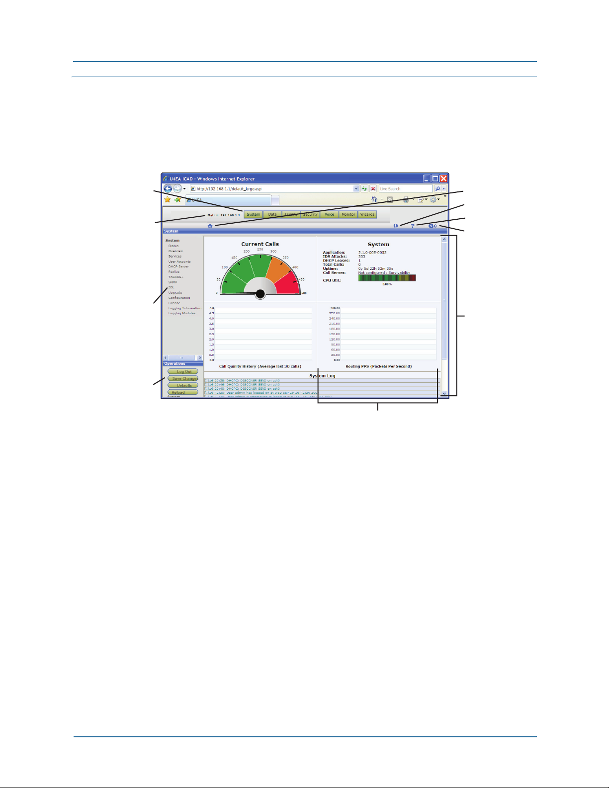
Figure 1
Button Bar
Unit Name
and Adress
Menu Pane
Operations
Pane
Components of the Web UI page
Assistance Icons:
• Home Page
• Information
• Help
• User Mode
Page Display
Pane
Panel within
the DisplayPane
Button bar
Each button represents a category of functions, which appear as links in the menu pane
on the left side of the window. The Web UI is open when the System > Status page
appears.
Assistance icons
Assistance icons provide the following services:
z Information–Provides product information by opening a new browser window and
connecting to the Web page of the manufacturer.
z Help–Displays an overview of the BSGX4e features and services.
z User mode–Selects the desired user mode:
S = Simple mode. Field explanations are displayed in the Web UI pages.
A = Advanced mode. Field explanations are not provided.
z Home–Returns the Web UI to its home page, which is the System > Status page.
22 NN47928-502
Page 23
1 Web UI introduction Window components
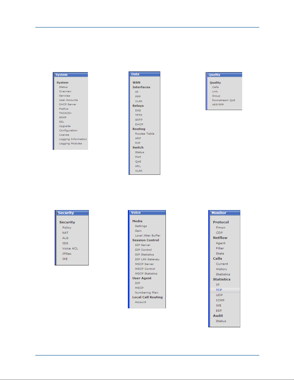
Menu pane
Click a link in the menu pane to load a corresponding configuration page in the display
pane. A list of menus changes appears with each button on the button bar.
System button Data button Quality button
Security button Voice button Monitor button
NN47928-502 23
Page 24

Window components 1 Web UI introduction
Operations pane
The following links perform system operations for the current session:
z Log Out – Logs out the user and returns to the log in screen. Unsaved configuration
changes are kept unless the unit restarts.
z Save Changes – Saves configuration changes to nonvolatile memory. (When
configuration changes are pending, the Save Changes button turns red.)
z Factory De faults – Erases the current configuration stored in memory and restores the
original, default configuration of the unit.
z Reboot System – Logs out the user and restarts the BSGX4e with the configuration
stored in memory. Unsaved configuration changes are discarded and the browser
connection to the unit is lost.
Operation pane notes
Configuration changes
Any configuration change you make takes effect immediately when you click an
Update or Apply button in the page that appears. However, those buttons do not
store the change in memory, so unsaved changes are lost if the unit reboots. You
must use the Save Changes button for permanent storage.
Reloading defaults
The Factory Defaults button erases any configuration changes you have made and
saved into memory. This button also resets the eth1 (LAN) interface to the default
address of 192.168.1.1. Added user accounts are erased, leaving the two default
accounts: admin and user.
CAUTION: After configuring the BSGX4e for your site, export a configuration file and
store it on a separate host so that you can retrieve the configuration if problems
arise. See Configuration on page 63
.
Display pane
The display pane displays the Web pages as you click on functional buttons or menu
links. These pages can be interactive configuration pages or informational status pages.
The page in the display pane can be segmented into panels for different types of data.
24 NN47928-502
Page 25

1 Web UI introduction Usage notes
Usage notes
This section provides helpful notes on using the Web UI.
Browser Requirements
The BSGX4e has been tested with Microsoft®‚ Internet Explorer®‚ and Mozilla®
FireFox
® browsers.
Internet Explorer must have the Adobe
must have the Adobe Flash Player plugin. Use the browser’s Manage Add-ons (Explorer)
or Add-ons (FireFox) command to obtain the plugin.
®‚ Shockwave®‚ Flash Object add-on. Firefox
Connecting to the BSGX4e
The basic BSGX4e installation and cabling is covered in the Quick Start Guide and the
Installation Guide on the Documentation CD. The following steps instruct you on
accessing the Web UI:
1. Connect a PC to one of the BSGX4e LAN ports, labeled
2. Open a Web browser. The BSGX4e has been tested with Microsoft
Explorer
3. Enter http://192.168.1.1 in the address bar of your browser.
4. On the User log in page, enter the default log in codes:
If you want to use the Initial Setup Wizard for the basic configurations tasks, select e
the
Guide on the Documentation CD for more information.
® and Mozilla® FireFox®.
User name: admin
Password: PlsChgMe!
Setup Wizard check box to immediately open the wizard. See the Initial Setup
Notes
1 through 4 on the box.
® Internet
z Font size – You may have to adjust the font size in the browser. If the text appears to
be overrunning its boundaries or overlapping other areas, decrease the text size. Use
the command on the
z Log in failure – If your log in fails on a new unit, retry the log in procedure to ensure
you did not make a typing error. Also, your PC can have a static IP address rather
than using DHCP to obtain a dynamic address.
If log in fails after having configured the unit, likely causes are a VLAN assigned to
the port to which your PC is connected, or the IP address of the LAN switch has been
changed. Use the CLI (connected to the serial port) to view or change parameters to
re-establish the Web UI connection.
z Connection failure – If you are working on more than one BSGX4e you must clear the
private data from the browser before connecting your PC to a different BSGX4e. The
BSGX4e places cookies and browser history records into your browser. The cookies
and browser history records prevent you from successfully connecting to a new
BSGX4e unit.
NN47928-502 25
View menu, or the keyboard shortcuts: Ctrl+ + and Crt+ –.
Page 26

Usage notes 1 Web UI introduction
Entering numerical data
The underlying architecture of the Web UI allows you enter numerical data in decimal,
hexadecimal, or octal format. If you enter configuration data in hexadecimal or octal and
then view the corresponding display page, you see the number has been converted to
decimal.
This can cause confusion for an ID field where the number is used only to identify a
record or profile. Nortel recommends that you use decimal numbers in these fields.
The Web UI processes any number that begins with 0x as hexidecimal and processes as
any number that begins with 0 as octal.
26 NN47928-502
Page 27
2 System pages
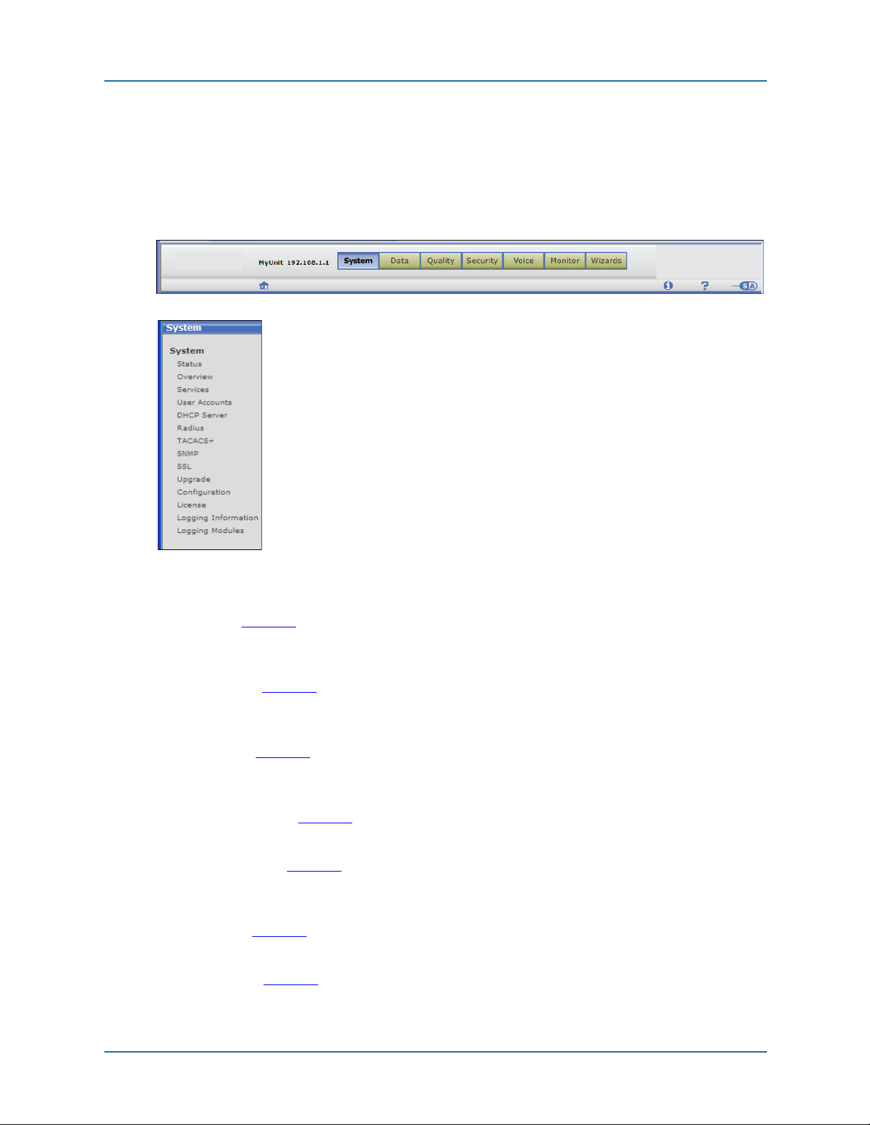
2 SYSTEM PAGES
This chapter describes the configuration and status
pages available from the
bar. The functional topics of the pages are listed in the
menu pane of the Web UI window, as shown in the
figure on the left.
System > Status page is the home page of the Web
The
UI and is the page appears when you log in.
System button on the button
The following list provides an overview of the configuration and status functions on the
System menu:
z Status (page 29)
Graphical displays showing call load and other operational data. Software version
and other system data displayed. A system log viewer shows the latest log entries.
z Overview (page 31)
Listing of more detailed system data. Change the unit name and country. Set
parameters of the command shell (used for CLI).
z Services (page 33)
Enable and configure ports for HTTP(S) and telnet connections. Configure DNS,
SNTP, and SSH services.
z User accounts (page 41)
Create and modify user accounts. Assign groups and privileges. Assign passwords.
z DHCP server (page 47)
The BSGX4e can provide DHCP service for devices connected to the LAN (eth1/vifn).
Modify the default profile or create a new one.
z RADIUS (page 53)
Configure RADIUS authentication service.
z TACACS+ (page 53)
Configure TACACS+ authentication service.
NN47928-502 27
Page 28

2 System pages
z SNMP (page 56)
Configuration for remote monitoring of the system.
z SSL (page 59)
Configure key and certificates for SSL encryption.
z Upgrade (page 62)
Load software and bootloader upgrades. Switch between software configurations.
z Configuration (page 63)
Display current system configuration parameters. Export or import a configuration
file.
z License (page 64)
Copyright statements from developers whose code is used in the Web UI.
z Logging information (page 64)
Configure message logging for which types of messages are sent to which
destinations.
z Logging modules (page 67)
Configure modules (system functions) for which message types are logged.
28 NN47928-502
Page 29
2 System pages Status page
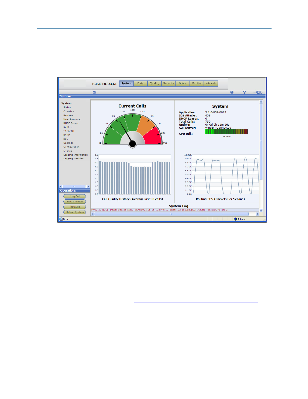
Status page
Figure 2 Status page
The system status page is display-only, there are no configuration items.
Descriptions of the panels in the display pane follow.
System > Status > Current Calls panel
This panel is a speedometer-type display that gives visual indication of the current call
load.
You can change the scale of the display by setting the maximum calls parameter in the
Session Controller, located under the Voice button in the Web UI. The default display is
set for 50 calls. See the section, Voice > Session Control > SIP Control on page 167
configuration details.
Perform the following steps to set the maximum call limit in either SIP or MGCP
protocols:
1. Click the
2. Configure the SIP or MGCP server.
3. Select that server on the SIP or MGCP control page.
4. Set the
NN47928-502 29
Voice button and navigate to the Session Control section in the menu pane.
Max Calls field on the SIP or MGCP control page.
, for
Page 30

Status page 2 System pages
System > Status > System panel
This panel displays the information shown in the following table.
Tab l e 3
Application The software version running in the unit.
IDS attacks The number of attempted attacks detected by the Intrusion Detection
DHCP leases The number of IP address leases issued when the BSGX4e functions
Total calls The cumulative number of calls processed by the BSGX4e during the
Uptime Cumulative running time since the last bootup. Displayed in years (y),
Call server The call server (SIP or MGCP) currently configured and operational
CPU Util Graphical presentation of current CPU utilization.
System > Status > System panel information
System.
as a DHCP server to LAN devices.
indicated uptime.
days (d), hours (h), minutes (m), and seconds (s).
status of the connection.
Survivability status – If VoIP services are unreachable, the BSGX4e
still provides service between IP phones on its LAN, and can send
some number of calls to the PSTN through the FXO port or an FXO
gateway.
Connected status – VoIP services are reachable.
System > Status > Call Quality History panel
Graphical display of call quality, based on Mean Opinion Score, averaged from the last
30 calls.
System > Status > Routing PPS panel
Graphical display of data packet rate through the BSGX4e routing engine.
The routing engine in the BSGX4e consists of the QoS quality groups, the routing table,
and NAT.
System > Status > System Log panel
Displays last 15 messages sent to the internal log.
Each log entry begins with a letter in parentheses, which maps to the first letter of the
severity level of the log entry (listed here in descending order of severity):
Emergency Notice
Alert Inform See Logging information on page 64
related information.
Critical Debug
Error Trace
for
30 NN47928-502
Page 31

2 System pages Overview page
Warning
Overview page
The system overview page displays system information, and it contains the following
configurable parameters:
the unit name displayed on the Web UI (left of the button bar)
the country of operation, which affects telephony settings
configuration of the CLI command shell
Figure 3
Overview page
The panels in the display pane are described in the following sections.
NN47928-502 31
Page 32

Overview page 2 System pages
System > Overview > System Information panel
The System Information panel shows various high-level system configuration items.
Further detail for some of the items:
Bootcode Ver – Version of the bootloader program
App. Ver – System software version
System Type – Model designation of this unit
Memory – RAM expressed as used/available
Up time – Cumulative running time since the last bootup Displayed in years (y),
days (d), hours (h), minutes (m), and seconds (s)
MAC 0 – MAC address for the WAN interface
MAC 1 – MAC address for the LAN interface
You can configure the following parameters with the
finished:
Unit name
Country
NOTE: After changing the Country parameter, Save the change and Reboot the system to
implement the change.
Countries have differing telephony standards including ring tones, ring cadence, and
emergency numbers. The Country parameter loads country-specific default values into
the unit. This affects Phone port parameters and LCR settings. See Voice > Local Call
Routing >Settings tab on page 186.
The BSGX4e unit name displayed to the left of the button bar.
The country of operation. Default is USA.
This selection sets several parameters that affect the characteristics of an
analog phone connected to the Phone port. See the paragraph below for
more details.
NOTE: The drop-down list of names has a divider line (---------). The
BSGX4e is certified for operation in those countries above the line. In
those countries listed below the line, the BSGX4e is not certified for
operation but you can use it for activities such as lab tests and field trials.
Modify button, click Update when
You can create ring tone patterns that override the country defaults using the CLI
command conf voice fxs ring.
System > Overview > Shell panel
This panel displays the configurable characteristics of the command shell used for the
CLI.
You can configure the Width, Prompt, and Timeout parameters with the
The configuration page is self-explanatory. Click
Update when finished.
Modify button.
System > Overview > System Hardware panel
This pane displays version levels the main hardware components of the BSGX4e.
32 NN47928-502
Page 33

2 System pages Services page
Services page
The services page is where you enable and configure various network services:
Web server – Enabled by default
Telnet server – Enabled by default
SNTP client – Disabled by default
SSH server – Enabled by default
DNS servers – Disabled by default
Dynamic DNS client – Disabled by default
Figure 4
Services page
Note that with some of these services (DNS, SNTP, DHCP), rather than having the
BSGX4e act as the service client, you can configure it as a relay that forwards LAN
requests to an external server. See the section Relays on page 78
.
The panels in the services page are described under the following headings.
NN47928-502 33
Page 34

Services page 2 System pages
System > Services > Web Configuration panel
The Web server allows remote administration of the BSGX4e using the Web UI connected
through the WAN or LAN ports. The server supports HTTP and HTTPS (HTTP over SSL)
protocols.
The BSGX4e Web server is enabled by default and is configured to use the standard
ports 80 (HTTP) and 443 (HTTPS). The Web UI uses the HTTP port by default. You can
disable the server or change the access ports with the
finished.
Firewall security policies must allow Web access from the WAN (eth0/ppp0/vif0)
terminating in the BSGX4e (self). This requires access for TCP traffic being routed to
ports 80 and 443. These security policies already exist by default. If you change the port
configuration for the Web server you must create new security policies.
Modify button. Click Update when
System > Services > Telnet Configuration panel
Telnet allows access to the BSGX4e through a remote terminal session. This is required
to access the CLI. The workstation connected to the BSGX4e WAN or LAN must have a
Telnet client.
The BSGX4e Telnet server is enabled by default and is configured to use the standard
port 23. You can disable the server or change the port with the
Update when finished.
Modify button. Click
A firewall security policy must allow Telnet access from the WAN terminating in the
BSGX4e (self). This requires access for TCP traffic being routed to ports 23. A security
policy already exists by default. If you change the port configuration for the Telnet server
you must create a new security policy.
34 NN47928-502
Page 35

2 System pages Services page
System > Services > SNTP Configuration panel
You can use the SNTP client to automatically set the time in the BSGX4e. The SNTP
client is disabled by default, requiring the time to be set manually. Use the Initial Setup
Wizard to set the time manually.
Rather than using this client service, you can configure the BSGX4e as an SNTP relay.
See Data > Relays > SNTP page on page 83
for the SNTP relay function.
Configure the following parameters to enable the SNTP client, click
finished:
Enabled Enables or disables the SNTP client
Source Source of the SNTP server configuration {auto | dhcp | user}.
• auto – From the DHCP server if possible; otherwise, the last userprovided configuration. (Default)
• dhcp – From the DHCP server. If the DHCP server cannot provide a
configuration, the server address is set to 0.0.0.0.
• user – User-provided configuration.
Server 1 IP address or FQDN of an SNTP server.
Server 2 Optional backup IP address or FQDN of an SNTP server.
Server 3 Optional backup IP address or FQDN of an SNTP server.
Server 4 Optional backup IP address or FQDN of an SNTP server.
Gmt Offset Time zone offset from Greenwich Mean Time (GMT).
{+ | –} <hh:mm> positive or negative; hours and minutes
Default is +00:00.
Sync Interval Interval for re-synchronization of the internal clock to the network time
(external clock) in days. Range is 1 – 31. Default is 7.
Update when
System > Services > SSH Configuration panel
The SSH server in the BSGX4e provides secure remote access to the BSGX4e client
device over an insecure network, such as the Internet. SSH version 2 is supported.
The BSGX4e SSH server is enabled by default. The default configuration is:
Port – 22
Host Keys – 640-bit DSA
Authentication Methods – keyboard, password and public key
Services – SSH and SFTP
You can disable the server or change the configuration parameters with the
button. Click
A firewall security policy must allow SSH access from the WAN terminating in the
BSGX4e (self). This requires access for TCP traffic being routed to port 22. A security
policy already exist by default. If you change the port configuration for the SSH server
you must create a new security policy.
A workstation connected to the BSGX4e’s WAN or LAN must provide an SSH client, such
as PuTTY and SSH secure shell.
NN47928-502 35
Update when finished.
Modify
Page 36

Services page 2 System pages
System > Services > DNS Configuration panel
The Domain Name Service (DNS) client in the BSGX4e sends requests to a DNS server on
the WAN. A DNS request is used to obtain an IP address required by the BSGX4e, such
as the IP address of a server that was specified by an FQDN. Two DNS servers can be
configured: a primary server and a secondary.
The DNS client is always active.
The default configuration of the DNS client is:
DNS1 – <address supplied by DHCP client>
DNS2 – <address supplied by DHCP client>
Domain – <name supplied by DHCP client>
Source – auto (dhcp)
The default configuration relies on the DHCP client to provide the DNS server addresses.
The DHCP client is enabled by default on WAN interfaces that use a dynamic address.
For WAN interfaces that use a static address, the DHCP client is disabled and you must
manually configure the DNS client. See the appropriate section in WAN on page 70
specifics on WAN configuration.
The BSGX4e also includes a DNS relay feature that can be used to override the DNS
client with a specific server address. For more information, see Data > Relays > DNS
page on page 78.
for
Configuration
The parameters can be set as follows, click Update when finished:
DNS1 Default is 0.0.0.0 with the
Leave blank (0.0.0.0) if
Enter an IP address for the primary DNS server if
NOTE: If
Source is set to auto, you can enter an address here that is
applied if a DHCP or PPP server cannot be found. See Application scenario
– DNS backup configuration.
DNS2 This is a backup server to
The description for
DNS1 also applies here.
Domain Domain name for the unit. Enter a name if
This value is cleared if
The DNS client adds the domain to the host before querying the DNS
server. Example: If the specified name is host and the specified domain is
domain.com, the query is for host.domain.com.
Source Source of the DNS configuration profile {
following paragraph for details.
Default is
auto.
Source is set to auto.
Source is set to auto, dhcp, or ppp.
Source is set to user.
DNS1.
Source is set to user.
Source is set to auto, dhcp, or ppp.
user | dhcp | ppp | auto}. See the
36 NN47928-502
Page 37

2 System pages Services page
The DNS client determines the DNS configuration to use based on the current value of
its
Source parameter:
user The DNS client retrieves the latest address/domain entered by the user.
dhcp The DNS client uses the address provided by an external DHCP server that
was discovered by the BSGX4e’s DHCP client. The DHCP client must be
enabled on the interface where the DHCP server is located.
If a DHCP server cannot provide an address, the DNS1 and DNS2 fields are
set to 0.0.0.0.
ppp The DNS client uses the DNS address provided by a PPP server on the
WAN. A PPP interface must be active on the WAN port. If the PPP server
cannot provide an address, DNS1 and DNS2 fields are set to 0.0.0.0.
auto
(default)
The DNS client gets its configuration automatically. It first attempts to get the
configuration from a DHCP or PPP server. If that fails, it uses the latest userdefined configuration stored in memory. See the following section, DNS
server sources, for more detail.
The auto parameter displays in one of three variations indicating the source
of DNS configuration in use:
• auto (dhcp)
• auto (ppp)
• auto (user)
DNS server sources
Determining the DNS server on the WAN that the client points to depends on a
combination of configuration settings:
z The BSGX4e default configuration includes the DNS client Source set to auto. The
DNS client looks for a server address first from a DHCP server, then from a PPP
server, and finally from the last stored user-defined address. If no address can be
found from any source, the displayed address is 0.0.0.0.
The DHCP client on the WAN port is also enabled by default. The DHCP client
searches for a DHCP server on the WAN for all interface types except PPP. With the
DNS client
server found by the search. If none is found, the DNS client searches for a PPP server,
which cannot be found if a PPP interface is not defined. The DNS client then looks for
the last user-defined address.
z If a PPP interface has been configured on the WAN port, the DHCP client has to be
disabled. The DNS client cannot contact the DHCP client, so it next attempts to get a
DNS address from the PPP server. If the PPP server does not provide a DNS address,
the DNS client looks for the last user-defined address. If no address can be found
from any source, the displayed address is 0.0.0.0.
z If Source is set to dhcp, the DNS client relies on the DHCP client to obtain a server
address, as in the preceding paragraphs. If the DHCP client fails to obtain an
address, there are no further searches and the displayed address is 0.0.0.0.
Source set to auto, the DNS client obtains an address from the DHCP
z If Source is set to ppp and a PPP interface is configured on the WAN port, the DNS
client uses the PPP server to obtain an address. If the PPP server fails to provide an
address, there are no further searches and the displayed address is 0.0.0.0.
NN47928-502 37
Page 38

Services page 2 System pages
z If Source is set to user, you must enter an address into the DNS1 field. The DNS client
does not perform any further address searches.
Application scenario – DNS backup configuration
This example shows how a user configuration can be stored as a backup while using the
auto-DHCP or auto-PPP configuration. If a DHCP or PPP server cannot be provide a DNS
address, the user configuration is automatically implemented by the DNS client.
1. The default configuration tries to auto-
connect to a DHCP server, then a PPP
server. The server provides the DNS
addresses and the domain name.
2. Click
Modify to
open the
configuration
page. Enter a
known DNS
server address
into the
DNS1
field, and a
secondary server
into
DNS2 if desired.
3. Leave the Source as auto.
4. Click
5. Click
Update to store this as a user configuration. A warning message displays stating
the changes are to be applied when
OK to return to the configuration page. Click Cancel to close the configuration
Source is user or auto(user).
page.
Source is left at auto, the user
Since
configuration is not activated unless a
DHCP or PPP server cannot be located.
When this occurs, the DNS Configuration
panel displays the user-defined
configuration.
38 NN47928-502
Page 39

2 System pages Services page
System > Services > Dynamic DNS Settings
Attention:
Dynamic DNS is not yet supported.
The Dynamic DNS service allows a remote host on the Internet to stay connected to the
BSGX4e WAN port. When the BSGX4e is configured with a dynamic IP address on its
WAN port, remote hosts cannot stay connected as the address of the BSGX4e changes.
Dynamic DNS allows the domain name data held in a name server to be updated in real
time. This allows the BSGX4e, servers, and other network devices to use a dynamic IP
address but still have a permanent domain name.
NOTE: To use this feature, open an account with a dynamic DNS service and register a
host name alias for the BSGX4e with the service provider. Two dynamic DNS services
have been qualified for use with the BSGX4e: dyndns.org and no-ip.com.
Dynamic DNS is disabled by default.
Configuration
Configure the BSGX4e’s dynamic DNS after opening an account with one of the qualified
service providers. Click the
follows, click
Service Select the service, from the pull-down list, with which you opened an
Enabled Disabled by default. Select yes to enable.
User The user name of the dynamic DNS account.
Password The password of the dynamic DNS account.
Host name Host name = user name + domain of the dynamic DNS account.
Period Refresh period. Update with current IP address if it does not match the
ForcedUpdate
Period
Wildcard When enabled, resolves *.domain.ext to the same IP address as
Update when finished:
Modify button in the display pane and fill in the fields as
account.
user.domain@ext
registered IP address. Range is 10 to 1440 min. Default is 60.
Forced refresh, whether or not IP address has changed, to avoid
expiration of host name. Range is 24 to 35 days. Default is 30.
domain.ext. Wildcards must be enabled on both the server and client.
Choices are:
nochg – Use when wildcard is not enabled on server (default)
on – Client enabled
off – Client disabled
NN47928-502 39
Page 40

Services page 2 System pages
When configured and enabled, the display panel
appears, similar to the Dynamic DNS Settings panel
in the figure to the right.
Most of the fields are self-explanatory. The
Status
field displays the following comments:
z GOOD
z GOOD: Additional nochg updates cause the
hostname to become blocked.
z ERROR: The hostname specified is not a fully-
qualified domain name.
z ERROR: The hostname specified does not exist
or in not in this user account.
z ERROR: The hostname specified does not exist
or not in this user account.
z ERROR: When talking to IP server
z ERROR: The username and password pair do not match a real user.
40 NN47928-502
Page 41

2 System pages User accounts page
User accounts page
This page is where you manage the user account security features of the BSGX4e. The
user accounts determine who can access the BSGX4e and what permissions they are
granted.
Figure 5
User Accounts Page
Technical reference
This section contains technical descriptions and reference information.
Terminology
Terminology applicable to user accounts:
Access – How you connect to the BSGX4e: Web, CLI, SSH, Telnet, FTP
Authorization – log in security protocol: SHA, RADIUS, TACACS+
Rights – Operation permissions: read, write
NN47928-502 41
Page 42

User accounts page 2 System pages
Default configuration
User interface with the BSGX4e is managed with user accounts, user groups, and user
rights. The BSGX4e is delivered with following predefined configurations:
z Two user groups – One for administrators (admins) and one for other users (users).
The admins user group is granted all access modes, and the users user group is
granted only Web and CLI access.
z Two user accounts – One for administrators (admin) and one for other users (user).
The admin account belongs to both predefined user groups (admins and users); the
user account belongs only to the users user group. Access passwords are controlled
in the user accounts.
z Three rights identifiers – One for the admins user group (admin) and the other two
for the users user group (useradv and userbasic). These identifiers are displayed
on the Rights tab page.
All rights are granted to admins; the two identifiers for the users user group grant
read-only permission to some commands, and read + write permission to other
commands. See Table 4
Each field on a Web UI page is a command parameter and the Update button
executes the command. A command acts on a configurable parameter referred to as
an “object.” Each object has an authority setting of either Admins or Users, which
works with the rights identifier to determine the permissions being granted. See the
next section for more detail.
.
NOTE: This predefined user management configuration cannot be deleted or renamed.
Rights
Whether you have read or read+write permissions for each command is determined by
the rights identifier, which assigns access modes based on a combination of the group
and the object authority settings. Your user account determines to which group you
belong, and the object authority is set at the factory. Table 4
Tab l e 4
User rights permissions
Log in Identifier Group Object Permissions
admin admin admins Admins read+write
user useradv users Admins read
user userbasic users Users read+write
demonstrates this principle.
42 NN47928-502
Page 43

2 System pages User accounts page
Passwords
Passwords are set in the User Account configuration page.
You are advised to change the default passwords during setup of the BSGX4e. The
default passwords are:
admin user = admin
user user = netcat
Password authentication can be internal (SHA) or external (RADIUS and TACACS+). For
external authentication, you must also configure the RADIUS or TACACS+ client (page
53) after configuring the user account.
You can have a situation where the user account is set for SHA authentication, but the
groups the user account belongs to are set for one of the external authentication servers.
This does not create a conflict, even if the user account is configured to inherit the
authorization properties from the group. The user can log in with either (SHA or external)
password.
Users are allowed three log in attempts. After that, the console is locked against all
log ins for 15 minutes or until the BSGX4e is power-cycled. All invalid log in attempts
are recorded in the audit log.
The admin user can change the password on any user account that has internal
authentication.
Configuration
Perform the following steps to create new, or modify existing, user accounts, groups, and
rights. You can create up to 20 user accounts and 10 user groups.
NOTE: If you are using RADIUS or TACACS authentication, read the section RADIUS
and TACACS+ on page 53 before configuring a user account here.
System > User Accounts > Users tab
You can create up to 20 user
accounts.
With the
the User Accounts page, click
New to create a profile.
To modify an existing profile,
click the profile name, then click
To remove a user account, select the check box next to the account name, then click
Delete. Note that you cannot remove the predefined admin and user accounts.
Users tab active on
Modify.
NN47928-502 43
Page 44

User accounts page 2 System pages
Fill in the fields as follows, click Update when finished:
Name Log in name of new account being added, or modification of existing account.
Access Access methods allowed to this user:
ssh – Secure Shell (SSH)
Web – Web User Interface (Web UI)
cli – Command Line Interface (CLI)
telnet – Remote access through a Telnet session
ftp – File Transfer Protocol (FTP)
If you do not select any access methods, the access defined for the groups to
which this user is assigned is used.
Auth Internal or external password authorization:
SHA – Internal authorization (Default)
RADIUS – External authorization (page 53
TACACS+ – External authorization (page 53
)
)
NOTE: For external authorization, you must also configure an authentication
client profile. Follow the RADIUS and TACACS+ page links above.
Group1 Assign the user account to a user group. Group1 is required, all other groups
are optional. A user can be assigned to up to five groups.
Review the section Rights on page 42
to determine the appropriate group.
Group2 - 5 Optional additional user groups to which a user account can be assigned.
To remove a user from a group, select none for the group parameter.
Password The password for the user account.
The authorization method (
Auth field) determines whether the password is
authenticated internally by the BSGX4e, or externally by a RADIUS or
TACACS+ server. For external authentication, you must also configure an
authentication client profile. See the links in the
Auth field above.
You can leave this field blank if you are using external authentication.
However, you can create a password here that can be used if the external
server cannot be reached.
Inherit Whether or not the user account inherits access and authorization settings
from the groups to which it belongs.
Default is yes.
Enabled Whether or not the user account is enabled. Default is yes.
44 NN47928-502
Page 45

2 System pages User accounts page
System > User Accounts > Groups tab
With the Groups tab active on
the User Accounts page,
click
New to create a profile.
To modify an existing profile,
click the profile name, then
click
Modify.
To remove a group profile,
select the check box next to the profile name, then click
Delete.
Fill in the fields as follows, click
Name Name of the new user group to be added or the existing user group to be
modified.
Access Access methods allowed to user accounts in this group.
A user account uses these access values only if its own access values are
not specified, and the access values of any preceding groups in its group
list are also not specified.
ssh – Secure Shell
Web – Web User Interface (Web UI)
cli – Command Line Interface
telnet – Telnet
ftp – File Transfer Protocol
Authorization Internal or external password authorization:
A user account uses the authentication method specified here only if its
own authentication method is not specified, and the authentication
method of any groups in its group list are also not specified.
SHA – Internal authentication (Default)
RADIUS – External authentication (page 53
TACACS+ – External authentication (page 53
For external authentication, you must also configure an authentication
client profile. Follow the RADIUS and TACACS+ page links above.
Update when finished:
)
)
Allow All Whether or not users associated with this group are allowed all rights, or
held to only those defined on the Rights page.
Default is no.
NN47928-502 45
Page 46

User accounts page 2 System pages
System > User Accounts > Rights
NOTE: The two permissions (Access mode) allowed are read and write. The execute
permission is not used.
As explained in the section Rights on page 42
, the permissions for any given command
are defined by the combination of the rights identifier and the object name in the
command’s authority parameter. Each page in the Web UI is the equivalent of a
command.
The three predefined identifier profiles and the groups to which a user account is
assigned determines the rights that a user has. The default users, groups, and rights
cover all usage scenarios. If you create new user accounts, you can copy these default
configurations to accomplish the access, authorization, and rights combination you
desire.
With the
Rights tab active on
the User Accounts page,
click
New to create a profile.
To modify an existing profile,
click the profile name, then
click
Modify.
To remove an identifier,
select the check box next to
the identifier name, then click
Delete. Note that you cannot remove the predefined
admin, useradv, or useradv identifier.
Fill in the fields as follows, click
Update when finished:
Identifier Name for new identifier profile.
Access mode Permissions granted by this record. Select all that apply.
read – View data
write – Change parameter values
NOTE: execute is not used at this time
Group name Name of the user group granted rights by this profile.
Object name Each object (command) has an authority field that is set to Admins or
Users. Select the name that sets the desired permissions in conjunction
with the user group that was selected:
Group Object Permissions
admins Admins read+write
users Admins read
users Users read+write
46 NN47928-502
Page 47

2 System pages DHCP server
DHCP server
The DHCP server in the BSGX4e provides dynamic IP addresses to hosts connected to its
LAN ports. This service is enabled by default. Optionally, you can assign static addresses
to LAN hosts.
For clarification, the BSGX4e also includes two other DHCP features:
DHCP relay (page 85) – Rather than having the DHCP server providing addresses
to LAN hosts, the relay service receives the host’s DHCP request and proxies it to
an external server. To the LAN hosts, the BSGX4e appears to be the server. To the
external server, the BSGX4e appears to be the requesting host. You must disable
the DHCP server to use the DHCP relay. The relay is disabled by default.
DHCP client (page 72) – The DHCP client requests a dynamic address from an
external server. The DHCP client can be enabled on either the WAN or LAN ports,
but not both. It is most common on the WAN with interfaces that do not require a
static IP address. The DHCP client can be enabled on the LAN if you have a DHCP
server connected to the LAN.
Figure 6
DHCP Server Pages
NN47928-502 47
Page 48

DHCP server 2 System pages
Functional characteristics
The DHCP server, as implemented in the BSGX4e, has the following characteristics:
Supports one address range per LAN interface (eth1 or vifn). Up to four virtual
interfaces (vif) can be configured on the LAN ports, one on each port.
Address range must be within the subnet of the interface.
Up to four servers can be configured— one on each interface configured on the
LAN ports.
Up to 500 IP addresses can be configured on each server.
Options can be enabled for each interface, vendor class, or MAC address.
Lease information is saved in non-volatile memory so it can be retrieved
immediately after a restart.
The DHCP server relies on DNS for name/address translation. It connects to a
DNS server through the DNS client (page 36
configured.
The DHCP relay (page 78) and DHCP client (page 71) must both be disabled on
eth1 to implement the DHCP server.
), which must be appropriately
Configuration
Perform the following tasks to configure the DHCP server.
System > DHCP Server > Pool tab
The DHCP server pool is where you configure the network parameters and assign an
option group.
A DHCP pool is automatically created for the eth1 LAN interface when the BSGX4e is
first initialized after bootup. IP addresses are leased from the address pool.
To create a new pool for a virtual (vifn) interface, click
and fill in the fields as described below.
To modify an existing pool, click eth1/vifn in the display to open the properties page,
then click
Modify to open the configuration page.
You can delete interface profiles by activating the check box next to the profile on the
display page, then click
Fill in the fields as follows, click
Delete.
Update when finished:
New to open the configuration page
48 NN47928-502
Page 49

2 System pages DHCP server
[interface] (1) The BSGX4e interface for which the server supplies addresses.
Default is eth1 (LAN).
Enabled (1) Enables or disables the DHCP server for the designated interface.
Default is enabled.
Subnet (1) The subnet that is to be served. Must be a subnet of the interface.
Default is 192.168.1.0.
Netmask (1) The netmask for the subnet.
Default is 255.255.255.0.
IP(1) The beginning address for the range of IP addresses that the
server can assign to hosts. Must be within the BSGX4e’s subnet.
Default is 192.168.1.50.
(range to)(1) The ending address for the range of IP addresses.
Default is 192.168.1.250.
Broadcast The broadcast address for the subnet.
Default is 192.168.1.255.
Lease The length of lease. Range is 1-7 days.
Default is 7.
Gateway The network gateway address.
Default is 192.168.1.1.
OptionGroup The name of an option group to be sent to the host.
Default is none.
(1) These fields are required. All remaining fields are populated with intelligent
default values if left blank. These fields can be modified after initial creation.
System > DHCP Server > Lease tab
This is a display-only page that shows the current leases.
The Expired field shows an asterisk (*) if the current system time is greater than the end
time of the lease. This indicates that the lease has expired.
The BSGX4e can accommodate a maximum of 500 leases for all pools.
System > DHCP Server > Option tab
The Option page is where you create groups, configure options, and assign the options to
groups. The option group can then be assigned to a specific interface, host, or vendor
class as needed.
A DHCP option contains information that is sent to a LAN client when it is assigned an IP
address by the DHCP server. It typically describes a network configuration and various
services that are available on the network.
Functional characteristics
The Group/Option feature has the following characteristics:
NN47928-502 49
Page 50

DHCP server 2 System pages
z A group cannot be deleted if it is referenced by another configuration entry on the
Pool or Host pages.
z A group cannot be renamed if it is referenced by another configuration entry on the
Pool or Host pages.
z A group cannot be modified after being created. If you need to change the group
option parameters, you must delete the option and create a new one.
z An option code can be assigned to different groups with the same or different value
for each group.
z Multiple option codes can be assigned to the same group.
z A maximum of 32 groups can be created.
Configuration
The Option page is divided into DHCP Group and DHCP
Option sections, as shown here.
1. Click
New under the DHCP Group heading and enter a name
for the new group.
2. Click
New under the DHCP Option and configure the
parameters as follows:
Id
Enter a number. If you enter
assigned.
Group
Code
Select the group name to which you are applying an option.
Select the option code to apply to the selected group.
new, the next sequential number is automatically
50 NN47928-502
Page 51

2 System pages DHCP server
Value
Enter an appropriate value for the selected code:
bootfile-name Text.
Identifies a bootstrap file.
domain-name Text.
The domain name the client must use when resolving
host names through a DNS.
domain-nameservers
IP address.
A list of DNS servers available to the client. Enter
multiple servers separated by a comma (,). List the
servers in order of preference.
NOTE: Read the DNS entry under the Functional
characteristics on page 48 for reference.
ntp-servers IP address or domain name.
A list of NTP (time sync) servers available to the client.
Enter multiple servers separated by a comma (,). List
the servers in order of preference.
option-150 IP address. Proprietary DHCP option.
Location of a TFTP server for proprietary terminals
(Cisco, for example).
option-151 IP address. Proprietary DHCP option.
Location of a SIP server for proprietary terminals
(Cisco, for example).
option-160 IP address. Proprietary DHCP option.
option-161 IP address. Proprietary DHCP option.
routers IP address or domain name.
tftp-server-name IP address or text.
time-offset Time format in hours:minutes (HH:MM) or in seconds
3. Click Update when finished.
Location of a TFTP server for proprietary terminals
(Polycom, for example).
Location of an FTP server for proprietary terminals
(Polycom, for example).
A list of routers on the client's subnet. Enter multiple
routers separated by a comma (,). List the servers in
order of preference.
Identifies a TFTP server. Supported by some DHCP
clients, required by others.
(NNNN).
The time offset from Coordinated Universal Time (UTC).
Specify time East of UTC as positive (+) and West as
negative (–).
NN47928-502 51
Page 52

DHCP server 2 System pages
System > DHCP Server > Host tab
The configuration parameters on this page are optional. Use them to reserve a specific IP
address for a given MAC address and assign an option group to that address.
Click
New to open the configuration page.
You can modify existing host profiles by clicking the
Id number on the display page.
You can delete host profiles by activating the check box next to the profile on the display
page, then click
Fill in the fields as follows, click
Delete.
Update when finished:
Id A unique identification number. Use “new” or enter a whole number.
MACAddress The MAC address of the host.
IPAddress The IP address to assign to this host. The address must be within
the subnet defined for the interface.
OptionGroup Choose an option group from the drop-down list.
If you choose a different group than that assigned to the entire
interface (Pool tab page), this setting overrides the interface setting
for this specific host.
Description Optional text to help identify the host.
System > DHCP Server > VendorClass tab
The configuration parameters on this page are optional. Use them to assign an option
group to a specific vendor class identifier of a LAN host. You can also specify an interface
(physical or virtual) to further define the option group application. The option group can
be applied only to the specified vendor class on the specified interface.
Click
New to open the configuration page.
You can modify existing host profiles by clicking the
Id number on the display page.
You can delete host profiles by activating the check box next to the profile on the display
page, then click
Fill in the fields as follows, click
Delete.
Update when finished:
Id A unique identification number. Use “new” or enter a whole number.
VendorClass The vendor class of the host device. This data is in the vendor’s
documentation or on their Web site.
Interface The interface (optional). Default is
none.
OptionGroup Choose an option group from the drop-down list.
This assignment applies only to this vendor class. This setting
overrides the interface setting for this vendor class
52 NN47928-502
Page 53

2 System pages RADIUS and TACACS+
RADIUS and TACACS+
The BSGX4e includes both the Remote Authentication Dial-In User Service (RADIUS)
and Terminal Access Controller Access-Control System Plus (TACACS+) clients to
establish external authentication security, rather than using the default internal SHA
method. To use either service, you must first establish an account on a RADIUS or
TACACS+ server. That can be your company’s server or a commercial service provider.
These clients provide external password authentication by sending the log in password
to an external server for authentication. The default SHA uses authentication internal to
the BSGX4e.
Technical reference
The process to establish RADIUS or TACACS+ authentication is as follows:
1. Establish an account on the RADIUS or TACACS+ server. The account information
you receive must include the server address, user name, secret key, and password.
2. Create a new user account or modify an existing account (see User accounts page on
page 41).
On the user account configuration page:
The user name must be the same as for the RADIUS or TACACS+ account.
Select RADIUS or TACACS+ for the authorization field.
The password field is optional, since the external account password is actually
used for log in. A password entered here is used as backup if the external server
cannot be reached.
3. On the RADIUS or TACACS+ configuration pages:
Select the user for which the RADIUS or TACACS+ account was established.
Enter the RADIUS or TACACS+ server IP address and the secret key.
The authentication clients in the BSGX4e have the following characteristics:
z Any user account that specifies RADIUS or TACACS+ for remote authentication uses
the password from the authentication server. If the server cannot be reached, the
password defined in the BSGX4e user account is used.
z Authentication records are mapped to users by their user account name. Every user
account that specifies external authentication must have its own authentication
record. Up to twenty authentication records can be referenced.
z Disabling an authentication record suspends authentication for the corresponding
user account. This prevents log ins by the user account until either its authentication
record is re-enabled or its authentication method (Auth field) is changed.
z Deleting a user account also deletes its authentication record.
z Clients are compatible with standard RADIUS or TACACS+ servers.
z Normal operation fully encrypts the body of the packet for secure communication.
TACACS uses TCP port 49 for transport; RADIUS use UDP ports 1812 and 1813.
z Client activity is reported in the system log (page 30).
NN47928-502 53
Page 54

RADIUS and TACACS+ 2 System pages
Configuration
Perform the following steps to create a RADIUS or TACACS+ authentication record.
NOTE: A user account (page 43) must be configured for external authentication before
the corresponding authentication record is created.
System > Radius
The Radius page displays existing authentication records and contains the buttons for
adding a new record or deleting an existing record.
Every authentication record that accesses the same RADIUS server must specify the
same field values, except for the
User and Secret fields.
To configure a RADIUS authentication record, click
You can modify an existing profile by clicking the
You can delete a profile by activating the check box next to the profile on the display
page, then click
Fill in the fields a described here, click
User The user account to which the authentication record applies. The user
Enabled Enable / disable the Radius client. The default is no (disabled).
Automatic Automatically binds the client to the interface specified in the Interface
Auth FQDN or IP address of the Radius authorization server that the client
Secret Shared secret the client uses for security.
Bind Binding IP address for the client. The IP address of the interface that the
Interface Physical interface through which RADIUS communicates if the
Delete.
Update when finished:
account must specify Radius authentication.
field. Select yes if DHCP is in use. The default is no (no binding).
uses.
server references. Typically, this is the IP address of the WAN interface.
Specify this value only if DHCP is not in use.
Automatic field is yes. eth0 = WAN
To clear the parameter, specify none.
New to open the configuration page.
User name on the display page.
54 NN47928-502
Page 55

2 System pages RADIUS and TACACS+
System >TACACS+
The TACACS+ page displays existing authentication records and contains the buttons
for adding a new record or deleting an existing record.
Configure a TACACS+ authentication record, click
You can modify an existing record by clicking the
New to open the configuration page.
User name on the display page.
You can delete a record by activating the check box next to the profile on the display
page, then click
Fill in the fields a described here, click
Delete.
Update when finished:
User The user account to which the authentication record applies. The user
account must specify TACACS+ authentication.
Enabled Enable / disable the TACACS+ client. The default is no (disabled).
Server IP address or FQDN of the TACACS+ server that the client uses.
Key Shared key for the client as determined by the server. If the key includes
a space character, enclose the entire value in double-quotes (“ “).
NN47928-502 55
Page 56

SNMP 2 System pages
SNMP
The BSGX4e contains an SNMP agent that allows for remote monitoring. The BSGX4e
cannot be configured through SNMP in the current version.
Figure 7
SNMP uses a Management Information Base (MIB) database. The MIBs are described in
IETF RFC 1213. SNMP traps are supported.
The SNMP agent replies only to SNMP version 2c requests. Apart from the system group,
which can be configured with write permissions, all MIBs are in read-only mode in this
version.
The SNMP agent sends the following traps:
SNMP agent configuration
ColdStart The BSGX4e has restarted
WarmStart SNMP agent has restarted
LinkUp An interface has become active
LinkDown An interface has become inactive
Authentication
Fail
SNMP traps are sent on port 162; this cannot be changed. Port 161, used by the SNMP
agent, must be open in the firewall to allow access for SNMP clients to reach the agent.
See SNMP security policy on page 127
56 NN47928-502
SNMP authentication has failed (such as when the wrong
community name is used)
.
Page 57

2 System pages SNMP
Configuration
The SNMP agent is enabled by default but not configured. Traps are disabled by default,
and no community is configured.
System > SNMP > Agent tab
Click Modify to configure the SNMP agent:
Enabled Enables the agent (boolean). The agent is initially enabled.
Port Port on which the agent listens. The default is port 161.
(range to) DO NOT USE. This field is removed in the next release.
SysLoc SNMP system location (sysLocation MIB); physical location of the
hardware.
SysCon SNMP system contact (sysContact MIB); contact person for this
hardware.
SysName SNMP system name (sysName MIB); administrator assigned to this
hardware.
The display page contains a
software versions of the host that is running the BSGX4e.
SysDesc field that is read-only. It reports basic hardware and
System > SNMP > Traps tab
Click Modify to configure SNMP traps:
Enabled Enable/disable transmission of traps. Default is
Comm The community string to authenticate access.
IP IP address of the management station that receives traps.
(range to) DO NOT USE. This field is removed in the next release.
System > SNMP > Community tab
Click New to add an SNMP community:
Community The community string. Used to authenticate access permission.
IP IP address of the management station that sends SNMP requests.
Access Select
read or read-write.
no (disabled).
NN47928-502 57
Page 58

SNMP 2 System pages
System > SNMP > Statistics tab
The statistic page is a read-only display of the SNMP agent performance. You can update
the display with the
button.
Field definitions are as follows:
Out Pkts Total number of Out SNMP messages.
In Pkts Total number of In SNMP messages.
In BadCommunityNames Total number of In messages with an unknown community name.
In BadVersions Total number of In messages with an unsupported SNMP version.
In ASNParseErrs Total number of In messages with ASN.1/BER errors.
In BadCommunityUses Total number of In messages with a disallowed operation.
In NoSuchNames Total number of In messages with “nosuchName” in error-status field.
In Toobigs Total number of In messages with “tooBig” in error-status field.
In GenErrs Total number of In messages with “genErr” in error-status field.
In ReadOnlys Total number of In messages with “readOnly” in error-status field.
Refresh button, and delete accumulated statistics with the Clear
In TotalSetVars Total number of Set-Request PDUs processed successfully.
In TotalReqVars Total number of Get-Request and Get-Next PDUs.
In GetNexts Total number of Get-Next PDUs.
In GetRequests Total number of Get-Request PDUs.
In GetResponses Total number of Get-Response PDUs.
In SetRequests Total number of Set-Request PDUs.
Out TooBigs Total number of Out Messages with “tooBig” in error-status field.
In Traps Total number of SNMP Trap PDUs accepted and processed.
Out GenErrs Total number of Out Messages with “genErr” in error-status field.
Out NoSuchNames Total number of Out Messages with “noSuchName” in error-status
field.
Out GetNexts Total SNMP Get-Next PDUs generated.
Out GetRequests Total SNMP Get-Request PDUs generated.
Out GetResponses Total SNMP Get-Response PDUs generated.
Out SetRequests Total SNMP Set-Request PDUs generated.
Enable AuthenTraps Permission to generate authentication-failure traps, enabled (1),
disabled (2).
Out Traps Total SNMP Traps generated.
Silent Drops Total number of In PDUs silently dropped.
58 NN47928-502
Page 59

2 System pages SSL
SSL
This section describes configuring the Secure Socket Layer (SSL). SSL provides a secure
connection to any device contacting the BSGX4e on well-known port 443 with TCP
protocol. This applies primarily to the WAN interface, but is also applicable to the LAN
interface. Traffic over an SSL connection is encrypted and authenticated to prevent
eavesdropping, tampering, or forgery.
Figure 8
The BSGX4e has a private SSL key, a certificate signing request (CSR), and a certificate
by default. You can normally create a new key (and accompanying certificate) only if the
existing key’s security has been compromised.
SSL configuration
Application notes
The Web UI accommodates one key and certificate. You cannot delete these in the Web
UI. However, you can cause a new key or certificate to be generated by modifying the key
or CSR profile.
If you modify the key profile, a new key is generated, and a new CSR is generated.
If you modify the CSR profile, a new request is generated.
You can also delete the key, certificate request, and certificate with the Command Line
Interface (CLI) console:
del ssl key rsa
del ssl csr x509
del ssl cert x509
Then, the steps for a new SSL configuration are:
a. Generate a new SSL key with the default values.
On the
b. Generate a new SSL CSR.
On the
c. Generate or import the SSL certificate.
On the
NN47928-502 59
Keys tab, click Modify then Update.
Cert Req tab, click Modify then Update.
Certificates tab, click Modify then Update.
Page 60

SSL 2 System pages
During the time that a profile is being regenerated, a new SSL connections cannot be
established. The
process, and displays
also have a status field.
Status field on the Keys page displays generating during the generation
OK when the process completes. The Cert Reqs and Certificates tabs
Configuration
As explained above, the default SSL configuration is applicable in most situations. This
section explains the configuration parameters in those situations where you need to
regenerate a key or a certificate, or a key and a certificate.
Any modification to the Keys or Cert Reqs profile causes regeneration.
System > SSL > Key tab
The BSGX4e has a private SSL key by default, which is randomly-seeded, 1024-bit, and
RSA encrypted. Normally, a new private key does not need to be generated unless the
security of the existing key had been compromised.
The process for generating a new key can take several minutes depending on the size of
the key. When key generation starts, the key used by the SSL server is deleted and a new
SSL connection cannot be created until a new key is available. When key generation
completes, the key used by the SSL server is set to the newly generated key. New SSL
connections can then be created.
To generate a new key, click the
parameter (the only parameter you can modify). Modifying this profile causes a new key
to be generated. Alternately, use the CLI command del ssl key rsa.
Type Type of encryption. The BSGX4e uses only RSA.
Bits Number of bits in key (512 | 768 | 1024 | 2048).
Default is 1024
Modify button on the Keys tab page and change the Bits
60 NN47928-502
Page 61

2 System pages SSL
System > SSL > Cert Reqs tab
This page is where you can create a new Certificate Signing Request (CSR), if needed. A
valid key must first be configured.
A CSR exists by default. It is an X509 certificate and is self-signed by the SSL module.
To generate a new CSR, modify any of the parameters on this page. Alternately, you can
delete the CSR with the CLI command del ssl csr x509. Then, come back to the
Req
tab and click the Modify and Update buttons to regenerate the default profile.
The fields on the CSR configuration page are self-explanatory.
The
Status field on the tab page displays the following:
no key There is no SSL key.
Cert
waiting for key
The certificate request is being generated.
generator…
ok Generation is complete; an SSL key is available.
The
PEMData field shows the actual CSR in the standard
PEM format.
The
PEMData field on the tab page displays the certificate request. This can be the self-
signed certificate generated by the SSL module, or it can be a certificate signed by an
external certificate authority.
System > SSL > Certificates tab
This page is where you designate the certificate as self-signed, or you import an external
certificate. You must have generated a key and a CSR before enacting this page.
If a new key and CSR has been generated, click the
page to its defaults, which is a self-signed certificate generated by the SSL module.
The only parameter you can set on the configuration page (
field. Your choice are
The default is self for a self-signed certificate.
Select NULL if you have a certificate from an external certificate authority.
self and NULL.
The certificate must be in PEM format with no header before the “----- BEGIN
CERTIFICATE -----” phrase. Copy the certificate text and paste it into the
Certificate text box. The certificate is checked to ensure it is in the correct PEM
format. If the format is incorrect, the certificate is rejected, an error message
displays, and the
Status field on the tab page shows invalid certificate.
Modify then Update buttons to set this
Modify button) is the Signed
NN47928-502 61
Page 62

Upgrade 2 System pages
Upgrade
Figure 9 Upgrade system image
Use the Upgrade page to import new system software image files and bootloader files.
You can store two image files and define which to use for booting the system.
The manual configuration and user settings you made persist through an image
upgrade.
You acquire system update files at Nortel’s support Web site.
System > Upgrade
Perform the following steps to import a new software image:
1. Acquire the new image file and store it on the PC connected to the BSGX4e.
2. In the upper panel, select the slot in which to load the new image. Normally, this is
the slot that is not currently in use. In the lower panel, the slot to boot from is
automatically detected as the slot to which the new image was loaded.
3. Use the
4. Click the Upgrade button. The importing process takes a few minutes. You are
notified when it is finished, and prompted to reboot the system.
Perform these steps to import a new bootloader file:
1. Acquire the bootloader file and store it on the PC connected to the BSGX4e.
2. Use the
3. Click the Upgrade button. You are notified when it is finished.
Browse button to navigate to the file stored in Step 1.
Browse button to navigate to the file stored in Step 1.
62 NN47928-502
Page 63

2 System pages Configuration
Configuration
The Configuration page has two tabs:
Tex t B ase d shows a display of the current user configurations. These are listed as
CLI commands.
Save/Restore is where you import and export a configuration file.
Figure 10
Best practises: After performing any manual configurations, save the changes, export a
configuration file and store it outside of the BSGX4e so that you can re-import the
configuration in the event of an emergency recovery.
Configuration file Save/Restore
System > Configuration > Save/Restore
Save
To save a file with the current configuration settings, click the Download button. You are
prompted to select the storage location on the PC connected to the BSGX4e.
Restore
Perform the following to restore a configuration using a saved configuration file:
1. Ensure the target configuration file is on the PC connected to the BSGX4e.
2. Click
3. Click the
4.
NN47928-502 63
Browse and navigate to the configuration file.
Restore button to import the configuration.
Reboot the system to implement the configuration. Changes are saved automatically
in this process.
Page 64

License 2 System pages
License
This is a display page that lists the copyrights of other companies’ products used in the
BSGX4e.
Logging information
Figure 11 Logging information
The BSGX4e logs event and error messages to various internal and external
destinations. Most of these logs are intended to assist in troubleshooting during a
technical support session and do not provide useful information for normal operations. If
you need to contact technical support, it is important to provide both system information
and hardware information about the unit. This information is displayed at System >
Overview > System Information panel on page 32.
However, the system (internal) log displays its most recent entries at System > Status >
System Log panel on page 30.
The Logging Information page allows you to configure the destination of each message
type (based on severity level) and the network configuration for external destinations. It
also displays logging statistics (Counters Info).
64 NN47928-502
Page 65

2 System pages Logging information
System > Logging Info > Logging Destination panel
This panel is where you configure the external server to receive UDP and/or syslog
messages. Log messages are compliant with the syslog protocol. The UDP section can
also be configured to send raw UDP messages to a PC that is reachable from the
BSGX4e.
External logging is not configured by default. Click the
configuration page:
UDP Logger IP For messages with UDP destination.
NOTE: This is for customer support and factory use. The
destination must be running a UDP logger.
UDP Logger Port For messages with UDP destination. Port of the receiving UDP
logger. Default is 2000.
Sys log IP For messages with syslog destination. IP address of a
receiving Syslog logger.
Syslog Port For messages with syslog destination. Port of a receiving
Syslog logger. Default is 514.
Syslog Facility For messages with syslog destination.
Syslog facility to use: localn, where n is 0-7.
Modify button to open the
System > Logging Info > Counters Info panel
These are read-only fields that display the following information:
MsgQTxErrors Number of errors when sending to a message queue.
MsgQRxErrors Number of errors when receiving from a message queue.
LogTxCount Number of messages sent.
LogRxCount Number of messages received.
Errors Number of generic errors from the logging system.
NN47928-502 65
Page 66

Logging information 2 System pages
System > Logging Info > Logging Map panel
This page is where you configure each message type for one or more destinations, or no
destination. As described in the next section, each functional module in the BSGX4e can
be configured for which message types it sends. Message types are defined by severity
level.
Click the
configured for the following destinations:
Modify button to open the configuration page. Each message type can be
Console Messages are displayed on the RS-232 console. This applies whether
or not you are logged in to the CLI.
NOTE: Excessive messages to the console can prevent you from
entering CLI commands.
UDP Messages are sent in raw UDP format to the UDP logger specified in
the System > Logging Info > Logging Destination panel
page.
NOTE: This is for customer support and factory use. The destination
server must have a UDP logger.
Syslog Messages are sent in syslog format to the syslog logger specified in
the System > Logging Info > Logging Destination panel
Internal Messages are stored in an internal buffer of limited size, filled in FIFO
order, but irretrievable after the unit restarts. The messages are
displayed in the System > Status > System Log panel
File Messages are stored in an internal file of limited size, filled in FIFO
order, and retrievable after the unit reboots. The contents are the
same as the System Log display on the Status page.
These logs are also saved in the compact flash in the /cf0usr/log
directory. A directory is created for each day and includes one or
several log files. Files can be exported to an external device using
SFTP. Files can be viewed using the following Unix commands
through a CLI terminal:
panel of this
on this page.
.
BSGX4e> cd log
BSGX4e> ls
..
2008-01-09
2008-01-10
BSGX4e> cd 2008-01-09
BSGX4e> ls
..
0
1
BSGX4e> cat 1
15:21:27: No need to upgrade ids-hw for s/w version 2.1
15:21:30: DHCPS: no vendor fixing
15:21:30: Using system DNS
display continues
66 NN47928-502
Page 67

2 System pages Logging modules
Table 5 describes the message severity levels and shows the default destinations.
Table 5
Severity
Level
0 Emergency Emergency operation error Internal buffer.
1 Alert Alert level operation error Internal buffer.
2 Critical Critical operation error Internal buffer.
3 Error Low-level operation error Internal buffer.
4 Warning Warnings, such as a system attack. Internal buffer.
5 Notice Notices Internal buffer.
6 Inform Informative messages Internal buffer.
7 Debug Debug messages, such as receipt of a
8 Trace Trace messages Not logged.
System message severity
Message
Level Description Default Destination
Logging modules
Not logged.
SIP signaling packet.
This pages lists the functional modules in the BSGX4e and shows which message types
are mapped to that function.
This page is intended to be used only for troubleshooting during a technical support
session. You may be directed by the support technician to change the severity mapping,
or to change the destination mapping (previous section).
CAUTION: Do not change the severity mapping unless so directed by technical support
personnel. Enabling the debug and trace messages degrades system performance.
To change the message mapping of any function:
1. Click the module name in the display panel to open the properties page.
2. Click the
3. Enable or disable the desired message types and click
NOTE: Changes are not persistent. Any changes you make are reverted to the default
settings with the next reboot.
Modify button to open the configuration page.
Update when finished.
NN47928-502 67
Page 68

Logging modules 2 System pages
68 NN47928-502
Page 69

3 Data pages
3 DATA PAGES
This chapter describes the configuration and status
pages available from the
bar. The functional topics of the pages are listed in
the menu pane of the Web UI window, as shown on
the left here.
The Data pages consist of various status and
statistics displays, and configuration pages related
to the WAN and LAN (switch) interfaces, relayed
network services, and traffic routing.
Data button on the button
The Data menu provides the following functions:
z WAN (page 70)
Configure the physical parameters of the WAN interface.
z Interfaces (page 70)
Configure the various interfaces that can be associated with the WAN and LAN ports.
z Relays (page 78)
Configure DNS, TFTP, SNTP, and DHCP relays for LAN devices.
z Routing (page 86)
Display ARP table; add static routes; configure proxy ARP; enable RIP daemon.
z Switch (page 95)
Display LAN switch status; configure LAN ports; set up layer 2 QoS; map MAC
addresses to ports; configure VLAN on the LAN switch.
NN47928-502 69
Page 70

WAN 3 Data pages
WAN
This section is where you configure the BSGX4e network (WAN) interface. Your choices
are:
Ethernet (eth0) [default]
PPP (pppn)
VLAN (vifn)
The BSGX4e has an eth0 interface configured by default. To modify this interface or to
add the other interface types, see the next section, Interfaces
.
Interfaces
The Interfaces section is where you configure the WAN and LAN interface protocols.You
can configure the following interfaces on the BSGX4e:
Tab l e 6 WAN interfaces
BSGX4e
IP over Ethernet (ethn)
PPP over Ethernet (pppn)
VLAN (vifn)
IP over VPN (vpnn)
Data > Interfaces > IP page
BSGX4e proprietary interface terminology:
eth0 – WAN
eth1 – LAN
This page is where you configure a WAN or LAN IP interface and view configuration data.
The BSGX4e has an eth0 andpeth1 interface by default.
Figure 12
IP Interface display pages
70 NN47928-502
Page 71

3 Data pages Interfaces
IP display pane
The display pane (Figure 12 above) shows the parameters of each WAN or LAN interface.
This is also where you configure new interfaces and delete existing entries.
Most of the fields are self-explanatory. Below are a few fields that need some explanation:
z The Lease obtained and Lease expires columns display N/A if DHCP is off or DHCP has
not assigned an IP address to eth0. Otherwise, the columns describe the DHCP lease
for the IP address assigned.
z The Speed column reports the current negotiated speed for eth0:
FULL100 – 100 Mbps, full duplex mode
HALF100 – 100 Mbps, half duplex mode
FULL10 – 10 Mbps, full duplex mode
HALF10 – 10 Mbps, half duplex mode
z The Configured Speed column reports the speed setting in the eth0 configuration:
either
(
AUTONEG (auto-negotiation enabled) or a specific speed and duplex mode
FULL100, HALF100, FULL10, or HALF10).
IP configuration
To configure a new interface, click New to open the configuration page. Fill in the fields
as shown below. Click
To modify an existing interface, click the
Properties page, then
To delete an entry, enable the check box next to the
then click
Delete.
Update when finished.
Inter designator in the display to open the
Modify to open the configuration page.
Inter designator on the display page,
CAUTION: Do not configure a PPP interface as an IP interface. The PPP profile (page 73)
creates the ppp0 interface.
Interface
value
IP Addr/
mask
Select the interface to be configured. This is applicable to eth(n), vif(n), and
vpn(n) interfaces.
You can specify a static address/mask using dotted-decimal or CIDR
notation (for example, 192.168.15.33/255.255.255.0 or 192.168.15.33/24).
You must disable the DHCP client if you specify a static address on an
interface. Virtual interfaces (vifn and vpnn) require a static address.
MTU Maximum Transmission Unit (MTU) of the interface (in bytes). This sets the
maximum packet size. Default is 1500 bytes.
DHCP client Enable/disable the DHCP client (on | off).
Default for eth0 is
on. Default for eth1 is off.
The DHCP client is off by default when creating a new interface. (See the
DHCP client
section below for more discussion.)
See the notes for the IP Addr/Mask field above.
Status Whether the interface is enabled or disabled (up | down). Default is up.
NN47928-502 71
Page 72

Interfaces 3 Data pages
Speed Applicable only to the eth0 interface on the BSGX4e.
Whether the speed and duplex mode for the interface is auto-negotiated or
explicitly specified.
For auto-negotiation, choose Auto (default).
To specify speed and duplex mode, select:
10Half – 10 Mbps, half duplex
10Full – 10 Mbps, full duplex
100Half – 100 Mbps, half duplex
100Full – 100 Mbps, full duplex
DHCP client
The DHCP client obtains a dynamic address from an external server for the interface on
which the client is enabled. The client can be enabled on either the WAN or LAN
interface, but not both.
Enable the DHCP client on the LAN if you have a DHCP server on the LAN.
The DHCP client is enabled on the WAN by default for the Ethernet interface of the
BSGX4e, and it is disabled for all other interfaces. This information is summarized in
Table 7
.
Tab l e 7
DHCP client status by interface
DHCP disabled DHCP enabled
Ethernet (ethn)
PPP(pppn)
VLAN (vifn)
VPN (vpnn)
In addition to the DHCP client, the BSGX4e also has a DHCP server for the LAN (page 47
and a DHCP relay that proxies requests from the LAN to an external server (page 85
).
You can apply only one of these three services to any given interface, the other two must
be disabled.
IP statistic
Each configured IP interface has a tabbed page that displays performance statistics.
Access this page by clicking the
Statistics tab.
Inter designator in the display pane, then click the
)
72 NN47928-502
Page 73

3 Data pages Interfaces
VLAN configuration
As part of the VLAN configuration process, the Data > Interfaces > IP page is where you
configure the virtual interface (vifn) as an IP interface.
NOTE: You must have created the virtual interface before performing this task. See Data
> Interfaces > VLAN on page 75 for VLAN process details.
Procedure:
Follow the instructions under the IP configuration
Select vifn from the Interface drop-down list on the configuration page.
Assign an IP address.
Create firewall security policies for the vifn interface. See VLAN security policies
heading above.
on page 127.
Data > Interfaces > PPP page
You can configure the BSGX4e to use a PPP link as its primary WAN interface. It is
designated as PPPoE on the BSGX4e. After the PPP profile is created you can view it as
the pppn interface in the
Data > Interfaces > IP display.
Figure 13
PPP interface page
PPP establishes the session between the BSGX4e and your service provider using its own
Link Control Protocol.
The BSGX4e’s PPP client discovers and authenticates a PPP access concentrator and
negotiates parameters, including an IP address, to establish the PPP link. The client
supports a single PPP session and is compliant with RFC 1661 (PPP), RFC 2516 (PPPoE),
and RFC 1662 (PPPoHDLC).
CAUTION: The PPP protocol uses a control signal to establish and maintain a connection
over the WAN link. This signal is critical to sustaining traffic through the link and should
be protected using QoS. See the section ARP/PPP page on page 121
NN47928-502 73
.
Page 74

Interfaces 3 Data pages
PPP configuration summary
You must perform the following process to establish a functioning PPP link as the WAN
interface:
1. Disable the DHCP client on the eth0 (WAN) interface. [page 71
]
2. Create a PPP profile. This displays as the ppp0 IP interface. [this section]
3. Create security policies for the ppp0 interface. [page 127
4. Enable NAT for the ppp0 interface. [page 134
]
5. Create a QoS group to protect the PPP control signal. [ARP/PPP page on page 121
]
]
NOTE: The Initial Setup Wizard performs all of these steps after completing the WAN,
QoS, and VoIP pages of the wizard.
To remove a PPP link, perform the above tasks in reverse order. However, do not delete
the QoS group if it is also being used by ARP.
Perform the following steps to delete the PPP profile created in Step 2.
1. De-activate the PPP profile.
a. Open the PPP profile page by clicking the
Profile number in the Interface > PPP
display page.
b. Click
c. Set the
Modify to open the configuration page.
Active field to no and click Update. You return to the profile page.
2. Delete the profile.
a. enable the check box next to the profile number on the display page.
b. Click
Delete.
Configuring a PPP profile
Note that only one PPP profile can be configured.
In the Data > Interfaces > PPP display pane, click
Fill in the fields as shown below. Click
Update when finished.
If a profile has already been defined, click the 0 in the
open the Properties page, then
Modify to open the configuration page.
Profile Default is 0 and cannot be changed.
L2 Interface Layer 2 interface name. Only one interface (eth0) is supported at this
time.
Active Specify yes to activate the profile. Specify no to de-activate the profile. (A
profile must be activated to enable PPP link negotiation; the profile must
be de-activated before it can be modified.) The default is no.
AuthProto Authentication protocol [PAP | CHAP]. The default is PAP.
On the BSGX4e, a PPPoE interface also has MSCHAPV1 and
MSCHAPV2 protocol options.
74 NN47928-502
New to open the configuration page.
Profile column in the display to
Page 75

3 Data pages Interfaces
SelfIP/Mask Optional static IP address and subnet mask (1.2.3.4/8) for the pppn
interface. Enter any if none is provided. Default is any.
MTU Maximum Transmission Unit (MTU) of the interface (296-1492 bytes).
The default is 1492 bytes.
MRU Maximum Receive Unit (MRU) of the interface (296-1492 bytes). The
default is 1492 bytes.
RestartTime Time interval before a request is re-sent (in milliseconds). The default is
3000 (3 seconds).
ServiceName Optional service name (up to 30 characters) to identify the profile.
Username Account user name (up to 64 characters) for logging in to the PPP access
concentrator.
Password Account log in password (up to 32 characters).
Data > Interfaces > VLAN
This section is where you assign the VLAN to an interface, thereby creating the virtual
interface (VIF
configuration process.
). This section also includes an overview of the entire VLAN (virtual LAN)
A VLAN is an independent network formed as a logical subcomponent of a physical
network. Since a VLAN functions as a separate network, its traffic is isolated from traffic
on other VLANs and traffic on the rest of the physical network.
Figure 14
VLAN interface page
NN47928-502 75
Page 76

Interfaces 3 Data pages
Technical reference
The VLAN function in the BSGX4e has the following characteristics:
z The BSGX4e supports IEEE 801.Q, which allows up to 64 VLANs across the four LAN
switch ports. Up to 16 virtual interfaces (vif0 - vif15) can be created on the Interface >
IP configuration page. VLANs are integrated into the host IP stack as separate layer 2
Ethernet interfaces.
z A VLAN is most commonly created on the LAN (eth1) interface. A VLAN can also be
created on the Ethernet WAN interface (eth0) of the BSGX4e.
z A VLAN cannot be configured on a PPP (pppn) WAN interface.
z By default, no VLANs or virtual interfaces are configured.
z A LAN port is configured as tagged or untagged when it is assigned to a VLAN. See
Data > Switch > VLAN on page 103
z A VLAN on any interface restricts access by allowing only the subnet addresses
defined by the VLAN. Thus, when a VLAN is activated on a LAN port, the LAN switch
can no longer be accessed through that port. A VLAN can be created on the Ethernet
WAN of the BSGX4e to establish trunking to a switch. In this configuration, the WAN
is accessible only by the trunk.
z A VLAN requires firewall security policies to define which traffic to accept or reject.
for more details.
Configuration overview
The complete VLAN configuration process requires the following steps:
1. Assign one or more LAN switch ports to the VLAN. Skip this step if you are creating a
VLAN for the WAN of a BSGX4e. [Data > Switch > VLAN on page 103
2. Create the virtual interface (vifn) profile for the VLAN and associate it to the physical
interface.
3. Configure the virtual interface and assign an IP address to it. [VLAN configuration on
page 73]
4. Create one or more firewall security policies so that the firewall allows traffic through
the virtual interface. [VLAN security policies on page 127
]
To delete a VLAN, delete the above configurations in the opposite order as listed.
]
76 NN47928-502
Page 77

3 Data pages Interfaces
Configuration procedure – Virtual interface
Perform the following procedure on the Data > Interfaces > VLAN page to create a virtual
interface profile for a VLAN.
Virtual interfaces are displayed as vif(n), where n is 0 through 15. A VLAN cannot be
configured on a PPP (pppn) WAN interface.
1. Click
New to open the configuration page.
2. Fill in the fields:
VID Specify the VID that was created on the Switch > VLAN page (See the
NOTE above).
interface This parameter is required. Physical Ethernet interface on which the
virtual interface is configured:
• eth1 for the LAN interface (default)
• eth0 for the WAN interface. If eth0 is specified, the WAN port is
automatically assigned to the VLAN.
Status Enables the virtual interface (on | off). Default is on.
Comment Optional comment. The comment can be up to 256 characters; if it
contains spaces, enclose the string in quotation marks. Special CLI
characters (such as ? and <tab>) are not allowed.
3. Proceed to Data > Interfaces > IP page on page 70
To modify an existing profile, click the profile’s
then
Modify to open the configuration page.
VID number to open the properties page,
To delete a profile:
a. Go to Data > Interfaces > IP page on page 70
and delete the virtual interface (vif)
that is associated with the VID to be deleted. VID/VIF association is shown on the
page in the next step.
b. Go to Data > Interfaces > VLAN on page 75
and delete the VLAN profile associated
with the VID.
to assign an IP address to the VIF.
c. Go to Data > Switch > VLAN
then click
NN47928-502 77
Delete.
and enable the check box next to the VID number,
Page 78

Relays 3 Data pages
Relays
This section describes using the BSGX4e as a relay for devices on its LAN that request
DNS, TFTP, SNTP, or DHCP services. The BSGX4e acts as a proxy and forwards any
such requests to the servers on the WAN specified by the services’ configurations. To a
LAN device, the BSGX4e appears to be a server; to the WAN server, the BSGX4e appears
to be a client.
All relays are disabled by default.
The DNS relay is enabled by default. All other relays are disabled.
Under the
client for DNS and SNTP services, and as a DHCP server. BSGX4e clients get their DNS
and SNTP data from servers on the WAN and then provides it for internal functions. The
DHCP server is enabled by default to provide IP addresses to your LAN devices. See the
sections Services page on page 33
For clarification, the BSGX4e also has a DHCP client on its WAN interface that obtains
an IP address for the unit from a DHCP server. This client is enabled by default. See
Data > Interfaces > IP page on page 70
System button on the button bar, the BSGX4e can also be configured with a
and DHCP server on page 47 for more information.
to access this parameter.
Data > Relays > DNS page
The DNS relay proxies requests (such as those required for Web browsing and email)
from devices located on the BSGX4e LAN to a server located on the WAN. To a LAN
device, the BSGX4e appears to be a server; to the WAN server, the BSGX4e appears to be
a client.
Figure 15
Relay – DNS page
78 NN47928-502
Page 79

3 Data pages Relays
The BSGX4e maintains a cache of successful DNS exchanges. If a DNS request is
already in the cache, the BSGX4e can reply to the request without referencing a DNS
server.
As described below, if the DNS relay configuration source is set to auto, the actual
configuration used depends on the settings of the DNS client. See System > Services >
DNS Configuration panel on page 36 for DNS client configuration.
NOTE: To use DNS relay, devices on the LAN must be configured — either through DHCP
server options (see page 49
) or manually—with the IP address of the BSGX4e LAN as
their DNS server.
Settings tab
To configure the DNS relay, click Modify on the Settings tab page, fill in the fields as
follows, and click
Update when finished:
Enabled
Yes to enable.
Default is
no yes.
DNS1 IP address of a DNS server. This value is stored and is then applied as
the “user settings” shown in Table 8
.
DNS2 IP address of a DNS server to use if DNS1 is not available. This value is
stored and is then applied as the “user settings” shown in Table 8
.
Source The source of the DNS relay’s configuration.
Your choices here are:
•
user – The last server or servers specified for the DNS1 and DNS2
parameters.
•
auto – The actual source depends on the choice made here combined
with the
Source field of the DNS client (page 36). The next table
shows how the DNS client and DNS relay interact to determine
the relay’s configuration source.
NN47928-502 79
Page 80

Relays 3 Data pages
Tab l e 8
Source Parameter Setting Can DHCP/PPP
DNS Relay DNS Client
user any or null -- --
auto DHCP or PPP yes --
auto DHCP or PPP no --
auto user -- yes
auto user -- no
auto auto yes --
auto auto no yes
auto auto no no
Sources for DNS relay configuration
provide DNS
configuration?
Did user provide
DNS Client
configuration?
Source of DNS
Relay configuration
User settings in
DNS Relay
DHCP or PPP
User settings in
DNS Relay
User settings in
DNS Client
User settings in
DNS Relay
DHCP or PPP
User settings in
DNS Client
User settings in
DNS Relay
Sessions and cache tabs
The Sessions tab shows current DNS sessions that are active in the BSGX4e.
The Cache tab shows the history of DNS exchanges.
Data > Relays > TFTP page
TFTP relay function proxies file requests between devices located on the BSGX4e LAN
and a single server located on the WAN. To the devices on the LAN, the BSGX4e appears
as a server; to the server on the WAN, the BSGX4e appears as a client.
80 NN47928-502
Page 81

3 Data pages Relays
Figure 16 Relay – TFTP page
You can cache frequently requested files. If the requested file is in the cache, the
BSGX4e can reply to the request without contacting the server.
File caching provides the following benefits:
z Avoiding unnecessary WAN bandwidth usage for frequently requested files, especially
if there are several user devices, such as VoIP phones.
z Improved scalability of VoIP service from a service provider, by reducing load on the
central file servers that are used for provisioning user devices.
NOTE: To use TFTP relay, devices on the LAN must be configured—either through DHCP
server options (see page 49) or manually—to use the BSGX4e as their TFTP server.
NN47928-502 81
Page 82

Relays 3 Data pages
Settings tab
To configure the TFTP relay, click Modify on the Settings tab page, fill in the fields as
follows, and click
Update when finished:
Enabled Enables the TFTP relay. Default is off.
Server IP address or FQDN of the external TFTP server.
If using the
DHCP client option, leave this field blank.
DHCP Enable to have the TFTP server address provided by the DHCP client on
the WAN interface of the BSGX4e {
Do not enable if you specified a server address for the
on | off}.
Server parameter.
Default is off.
Allow Types of TFTP messages to relay {get | all}. Default is get.
Sessions Maximum number of concurrent TFTP sessions. This ensures that the
CPU is not monopolized by TFTP packet relays. Default is 50.
Sessions tab
This page shows the current TFTP sessions active in the BSGX4e.
Cache tab
This page is where you enable and configure the caching feature. You must also specify
which files to cache on the Files tab page.
To configure caching, click
click
Update when finished:
Enabled Enables TFTP file caching. Default is off.
Size Size of the file cache in MB (1-16). Default is 6 MB.
Refresh Cache refresh interval (in minutes). Default is 240 minutes (4 hours).
Download Method for downloading files into the cache:
Server IP address or FQDN of the TFTP or FTP server.
User User name if downloading files by FTP.
Modify on the Cache tab page, fill in the fields as follows, and
• auto – Files are saved to the cache while being downloaded by the
TFTP relay function.
• tftp – Files are downloaded into the cache using an internal TFTP
client.
• ftp – Files are downloaded into the cache using an internal FTP client.
Default is auto.
Password Password if downloading files by FTP.
82 NN47928-502
Page 83

3 Data pages Relays
Files tab
All files that you want to cache have to be named specifically. This page is where you
specify the files, and where you view all existing cached files. The cache can list up to 50
files.
To specify files for caching, click
and click
To delete an entry, enable the check box next to the
then click
Update when finished.
Delete.
Index Enter any number from 1 to 50 that is not already in use.
Name The exact name of the file to be cached.
New on the Files tab page, fill in the fields as follows,
Data > Relays > SNTP page
Figure 17 Relay – SNTP page
Index number on the display page,
The SNTP relay proxies requests from devices on the BSGX4e LAN to a server located on
the WAN. To the devices on the LAN, the BSGX4e appears as a server; to the server on
the WAN, the BSGX4e appears as a client.
NOTE: To use SNTP relay, devices on the LAN must be configured — either through
DHCP server options (see page 49
server.
NN47928-502 83
) or manually—to use the BSGX4e as their SNTP
Page 84

Relays 3 Data pages
Settings tab
To configure the DNS relay, click Modify on the Settings tab page, fill in the fields as
follows, and click
Update when finished:
Enabled
Yes to enable. Default is no.
Source The source of the SNTP relay’s configuration.
Your choices here are:
•
user – The last server specified for the Server parameter.
•
auto – The actual source depends on the choice made here combined
with the
Source field of the SNTP client (page 35), even if it is
disabled. Tab l e 9
relay interact to determine the relay’s configuration source.
Server IP address or FQDN of an external SNTP server. This value is stored, but
is used only when the source parameter is
GMT Local time offset from Greenwich Mean Time in +/– hours. Default is 0.
Specify this offset only if the LAN devices cannot provide their own offset.
If the devices can provide an appropriate offset, set this parameter to 0.
Tab l e 9
Sources for SNTP relay configuration
Source Parameter Setting Can DHCP
provide SNTP
SNTP Relay SNTP Client
configuration?
below shows how the SNTP client and SNTP
user.
Did user provide
SNTP Client
configuration?
Source of SNTP
Relay configuration
user any or null -- --
auto DHCP yes --
auto DHCP no --
auto user -- yes
auto user -- no
auto auto yes --
auto auto no yes
auto auto no no
Sessions tab
This page shows the current SNTP sessions active in the BSGX4e.
User settings in
SNTP Relay
DHCP
User settings in
SNTP Relay
User settings in
SNTP Client
User settings in
SNTP Relay
DHCP
User settings in
SNTP Client
User settings in
SNTP Relay
84 NN47928-502
Page 85

3 Data pages Relays
Data > Relays > DHCP page
Figure 18 Relay – DHCP page
The DHCP relay proxies requests from devices on the BSGX4e LAN to a server located on
the WAN. To the devices on the LAN, the BSGX4e appears as a server; to the server on
the WAN, the BSGX4e appears as a client.
For clarification:
z The BSGX4e has a DHCP client that obtains an IP addresses for the unit from an
external DHCP server. This client is normally enabled on the WAN interface.
Optionally, it can also be enabled on the LAN interface.
z The BSGX4e has a DHCP server to provide IP addresses to devices on the LAN. This
server is enabled by default.
You must perform these tasks to make the DHCP relay functional:
1. Disable the DHCP server on the LAN interface. [DHCP server on page 47
]
2. Ensure DHCP client is not enabled on the LAN interface. [Data > Interfaces > IP page
on page 70]
3. Disable NAT on the WAN interface. [Security > NAT > Interfaces tab on page 134
]
4. Create a security policy to allow traffic from the external DHCP server to the DHCP
relay. [DHCP relay security policy on page 128
]
5. Configure the DHCP relay:
Enabled Enable (
Default is
yes) or disable (no) the DHCP relay.
no.
Server IP address or FQDN of the external DHCP server.
NN47928-502 85
Page 86

Routing 3 Data pages
Routing
This section describes the routing configuration options in the BSGX4e, which consists
of a routing protocol table and an Address Resolution Protocol (ARP
When a network node sends data to an IP address on its subnet segment, it broadcasts
an ARP request to resolve the IP address to an Ethernet MAC address.
Technical reference
The configuration topics in this section refer to three separate protocols that each
maintain their own data structure. Each protocol is used for a separate purpose:
ARP runs over Ethernet. It translates an IP addresses to a MAC addresses on
Ethernet networks.
Internet Protocol (IP) operates at a higher level to route IP packets to addresses on
the Internet. It automatically records dynamic entries in a routing table to define
routes to destination IP addresses. Static routes can also be configured.
The Routing Information Protocol (RIP) uses a routing daemon. RIP is used in the
BSGX4e only if the daemon is manually started. The daemon then listens for RIP
messages on the WAN interface from other routers on the network. It uses the RIP
message information to maintain the routes in the RIP table.
Functional characteristics include:
) table.
z Routing table entries can be dynamic (automatic) or static (manual).
A dynamic ARP entry is automatically configured when an IP interface is created or
enabled. It is deleted when the IP interface is removed or disabled.
A static ARP entry is manually configured and must be manually deleted. Static
routes cannot be modified after creation. You must delete the route and re-create it.
z The ARP table only maps IP addresses within the IP sub-network assigned to the
device.
z ARP runs over Ethernet only. It does not run on non-Ethernet interfaces such as PPP,
frame relay or VPN interfaces.
z Each packet contains a destination IP address. If the destination address is within
the address range specified for a route, the route is applied to the packet. A default
route does not specify a destination address range; instead, it applies to any packet to
which no other route applies. The destination address is entered as 0.0.0.0.
86 NN47928-502
Page 87

3 Data pages Routing
Data > Routing > Routes Table
View dynamic routes and configure static routes in the routing table on this page.
Figure 19
Dynamic routes are automatically created when IP interface are created or enabled. It is
possible to delete dynamic routes, but this is not recommended.
Use the following procedure to create a static route:
1. Click
2. Fill in the fields as follows:
Routing Table page
New to open the configuration page.
Destination Destination IP addresses and mask for which the route applies. To
add a default route to the table, specify the destination as 0.0.0.0, or
enter the word default.
Gateway IP address of the gateway. The gateway must be reachable from the
BSGX4e. Do not use this field if you specified an interface address.
Interface Output interface for the route. Do not use this field if you specified a
gateway address.
NN47928-502 87
Page 88

Routing 3 Data pages
Data > Routing > ARP
Address Resolution Protocol (ARP) is a network layer protocol that automatically maps IP
addresses to hardware Media Access Control (MAC
Use the ARP page to manually create an ARP table entry, to delete an entry, to flush the
table of all entries, and to configure an ARP proxy.
NOTE: ARP traffic is essential for the maintenance of the ARP table. Therefore, the
manufacturer recommends this traffic be protected from packet loss by placing it in a
QoS quality group. See the section ARP/PPP page on page 121
instructions.
ARP Table tab
Figure 20 ARP Table page
) addresses.
for configuration
This tab page is where you create a static ARP entry for a known host by associating the
hosts’s IP address with its MAC address.
Click
New to open the configuration page. The fields are self-explanatory.
Click
Flush to delete all dynamic entries from the ARP table.
88 NN47928-502
Page 89

3 Data pages Routing
Proxy ARP tab
Figure 21 Proxy ARP page
Proxy ARP enables the BSGX4e to transparently connect hosts that belong to different
networks without having to configure default gateways, routes, or other network
parameters.
This section describes the general proxy ARP configuration process. It also includes an
application scenario where a BSGX4e is inserted into an existing network that used a
firewall/router/NAT appliance as its WAN interface. In this scenario, the firewall
becomes a device on a BSGX4e VLAN, thus creating a sub-network that is proxied to the
Internet through BSGX4e’s WAN interface.
When a host on a network accessible to the BSGX4e’s WAN port sends an ARP request
through the BSGX4e to a device on its LAN, the BSGX4e responds to the request by
supplying its own MAC address (WAN port’s MAC) as proxy for the LAN device. The
sending host caches the BSGX4e’s MAC address with the proxy device’s IP address. All
subsequent traffic between the hosts, sent as normal (as if on the same subnet), is then
routed by the BSGX4e.
A similar process occurs in the reverse direction. When a host on the BSGX4e’s LAN
sends an ARP request to a host on a remote network, the BSGX4e responds with the
LAN’s MAC address. The process then repeats as described in the preceding paragraph.
Technical reference
Proxy ARP is applicable to both WAN and LAN interfaces. Can be enabled or
disabled on each interface and works with VLANs on WAN or LAN interfaces.
NOTE: If you use a VLAN with proxy ARP, the VLAN must be created before the proxy is
configured. See Data > Interfaces > VLAN on page 75.
Can be establish only from interfaces that use ARP, which are eth0, eth1, and
vifn. A proxy ARP is not supported on PPP, VPN, or FR interfaces.
NN47928-502 89
Page 90

Routing 3 Data pages
Works with static or dynamic WAN IP address assignments, depending on the
configuration. The more standard configurations–like that in Configuration
example 1–can use a dynamic address. More specialized configurations–like that
in Configuration example 2
Automatically creates dynamic ARP route table entries and firewall security
–require a static address.
policies as needed. Deleting or disabling a proxy ARP removes the corresponding
ARP route table entries and security policy.
Serves as a proxy for a LAN device in the outbound direction. For the reverse
traffic direction, the LAN device must be configured with the BSGX4e as its
default gateway. A separate proxy must be configured for inbound and outbound
traffic.
User can create static firewall security policies for existing proxy ARP
configuration profiles.
A proxy can be established for a specific IP address.
Maximum of 32 proxies can be configured.
Configuration
Terminology:
eth0 – WAN interface
eth1 – LAN interface
vifn – Virtual interface
In the display pane, click
below. Click
Update when finished.
To modify an existing entry, click its
New to open the configuration page. Fill in the fields as shown
Id number in the display pane.
To delete an existing entry, activate the check box next to the profile on the display page,
then click
Delete.
To configure a new proxy ARP:
1. Navigate to the
2. Click
New to open the configuration page.
Data > Routing > ARP page, Proxy ARP tab.
3. Fill in the fields:
Id Enter
new to create a new entry.
From/To Select the interfaces that correspond to the direction of the traffic. If a VLAN
has been configured, its virtual interface is in the drop-down list.
IP The destination address and mask for which this proxy is being created.
<address/mask>
Enable To enable of disable this proxy function.
4. Click
Update when finished.
90 NN47928-502
Page 91

3 Data pages Routing
Configuration example 1
The diagram in Figure 22
shows two proxies established (one in each direction) between
a subnet on the WAN and a subnet on the BSGX4e LAN. The two proxies would be
configured as follows:
Field Value (Proxy 1) Value (Proxy 2)
Id <ID 1><ID 2>
From eth0 eth1
To eth1 eth0
IP 192.168.152.0/24 192.168.2.0/24
Enable yes yes
Figure 22
ARP request to 192.168.2.0.
BSGX4e responds to request
and proxies traffic.
Proxy ARP – General configuration example
Subnet A
192.168.2.0/24
WAN
(Eth0)
O
N
H
EC
T
ICAD
0
G
S
S
E
N
I
S
BU
NET 10/10
ER
ETH
TATUS
S
1234
AN
W
LAN
(Eth1)
S
E
I
G
O
L
x
4
Y
A
W
E
AT
ARP request to 192.168.152.0.
BSGX4e responds to request
and proxies traffic.
Proxy ARP Parameters
From To Address
Eth0 Eth1 192.168.152.0/255.255.255.0
Eth1 Eth0 192.168.2.0/255.255.255.0
Subnet B
192.168.152.0/24
NN47928-502 91
Page 92

Routing 3 Data pages
Configuration example 2
The diagram in Figure 23
shows the scenario where a BSGX4e has been inserted into a
existing network that was using a firewall appliance for WAN interface. The result of this
configuration is that the firewall still functions as if connected directly to the Internet.
In this configuration, you cannot have VoIP devices connected to the LAN side of the
firewall in the data VLAN (Vif1). VoIP devices must be connected directly to the BSGX4e
LAN.
Proxies
The two proxy routes needed for this scenarios are as follows:
Field Value (Proxy 1) Value (Proxy 2)
Id <ID 3><ID 4>
From eth0 vif1
To vif1 eth0
IP 1.1.1.2/32 1.1.1.0/24
Enable yes yes
Firewall security policy and QoS group
This configuration requires a firewall security policy for the incoming (eth0
→ vif1)
traffic, which you must add manually.
This example uses the default QoS quality group “control” to perform the downstream
QoS functions. You must create this quality group, if it was not already created by the
Initial Setup Wizard. See Quality > Group > Group tab on page 112
for a detailed
discussion.
On the
and leave all other parameters at default values. See the section Policy on page 125
Security > Policy page, create a new policy with the following parameter values,
for
general instructions on security policies.
From eth0
To vif1
Dest IP 1.1.1.2
QoS control
92 NN47928-502
Page 93

3 Data pages Routing
Figure 23 Proxy ARP – Subnet with firewall
Proxy ARP Parameters
From To Address
Eth0 Vif1 1.1.1.2/255.255.255.255
Vif1 Eth0 1.1.1.0/255.255.255.0
WAN (Eth0)
LAN (Eth1)
Vif0
VoIP VLAN
192.168.3.0/24
INTERNET
1.1.1.1/24
S
U
T
A
T
S
N
A
W
Vif1
Data VLAN
192.168.2.0/24
Firewall
Proxy ARP
1.1.1.0/24
S
E
I
G
O
L
O
N
H
C
E
T
x
4
D
A
IC
Y
A
W
E
T
00
/1
0
1
T
E
N
R
E
H
T
E
4
3
2
1
A
G
S
ES
N
I
S
U
B
1.1.1.2
Physical Network
Logical Network
NN47928-502 93
Page 94

Routing 3 Data pages
Data > Routing > RIP
Figure 24 RIP page
The BSGX4e executes dynamic routing by enabling RIP (Routing Information Protocol).
RIP is a simple routing protocol that is part of the TCP/IP protocol suite. The BSGX4e
supports RIP versions 1 and 2.
The RIP daemon is disabled by default and must be started manually. When started, it
listens for RIP messages on the WAN interface and uses that information to store routes
in a table.
Functional characteristics
z For RIP to be effective, all routers in the network must support RIP version 1 or
version 2. Version 2 is recommended. RIP v2 supports RIP v1 capabilities and also
provides:
Variable-Length Subnet Masks (VLSMs) – Support for next-hop addresses, which
allows route optimization in certain environments.
Multicasting – Multicasting, instead of broadcasting, reduces the load on hosts
that do not support routing protocols.
z The BSGX4e is installed at the edge of the network and is intended to run NAT. Thus,
it only listens to RIP messages on its WAN interface or interfaces; it does not support
RIP on its LAN interface.
z RIP requires a firewall security policy for incoming messages on port 520.
CAUTION: An open port on the WAN interface can be a security risk.
z RIP broadcasts routing information to its neighboring routers. Therefore, it consumes
some of the bandwidth.
Configuration
The only parameters you can change are starting RIP and selecting the version.
94 NN47928-502
Page 95

3 Data pages Switch
On the Daemon tab of the RIP page, click Modify to open the configuration page and
change the settings as needed.
The Routes tab displays the routes that the RIP daemon has stored.
NOTE: You must create a firewall policy to allow RIP responses into the BSGX4e. See RIP
security policy on page 129.
Switch
The LAN switch in the BSGX4e implements a non-blocking switch fabric, enabling
packet switching at wire speed over all ports.
z The switch provides four LAN ports, displayed as 0-1 through 0-4.
The switch also has an uplink port displayed as 0-0. This port is not configurable and
is made visible only for diagnostic purposes. Port 0 connects the LAN switch to the
processing functions of the BSGX4e.
z Within the BSGX4e, the switch passes traffic from LAN hosts to the LAN switch
interface (eth1). Traffic destined for the Internet is then routed to the WAN interface.
The switch also routes traffic from a host on one LAN port to a host another LAN port.
z A functional LAN switch requires configuration of both the LAN ports (this section)
and the eth1 LAN interface. The eth1 interface is configured by default. See Data >
Interfaces > IP page on page 70 for the interface display.
Data > Switch > Status page
This page is a status display of the LAN port configurations.
Figure 25
LAN status page
Clicking on the port number takes you to the same configuration page as the Data >
Switch > Port tab.
NN47928-502 95
Page 96

Switch 3 Data pages
Port page
This page is where you configure the BSGX4e LAN ports and view port related statistics.
Figure 26
LAN ports page
This page has three tabs:
Port tab is where you configure the LAN switch ports.
Mirror tab is a diagnostic tool where you can mirror one port to another.
Stats tab displays port statistics.
Data > Switch > Ports tab
All ports are configured by default for auto negotiation of speed and duplex mode; flow
control is disabled; and the port is enabled.
You can modify each port’s default configuration. The port can be manually configured
for:
z speed of 10Base T or 100Base T
z duplex mode of half or full duplex, and
z flow control to provide back pressure (forced collision) for half duplex mode and
pause frames for full duplex mode
NOTE: Flow control must not be enabled if layer 2 QoS is enabled. See QoS page on page
98.
To modify a port’s configuration, click the port number in the display to open the
properties page, then click
Modify to open the configuration page:
96 NN47928-502
Page 97

3 Data pages Switch
Port Display only. The port being configured.
Speed The speed and duplex mode:
•
Auto – Auto-negotiate speed and duplex mode
•
10Half – 10Base T speed; half duplex
•
10Full – 10Base T; full duplex
•
100Half – 100Base T speed; half duplex
•
100Full – 100Base T; full duplex
Default is
auto.
Enabled Port is enabled or disabled.
Default is
yes (enabled).
Flow Ctrl When enabled, provides back pressure (forced collision) for half
duplex mode and pause frames for full duplex mode.
Default is
no (disabled).
Data > Switch > Mirror tab
This tab page configures port mirroring, which duplicates traffic from one port to
another.
CAUTION: Port mirroring is intended for troubleshooting only. When finished, remove
the mirroring configuration so that unit performance is not degraded.
Technical reference
z Mirroring can be configured either for outbound traffic or for both inbound/outbound
traffic.
z Port mirroring applies to LAN ports only.
z The mirroring port and the port being mirrored should have the same speed.
z To stop mirroring, set the Direction parameter to none.
Configuration
In the display pane, click
below. Click
Update when finished.
New to open the configuration page. Fill in the fields as shown
To delete an entry, enable the check box next to the port number on the display page,
then click
Delete.
Port Port whose traffic is mirrored. {0 | 1 | 2 | 3 | 4}
To Destination port where the mirrored traffic goes {1 | 2 | 3 | 4}. If mirroring is
in progress, the default is the current destination port.
Direction Direction of traffic to mirror (both | out | none). Default is both. Specify
none to suspend mirroring.
Data > Switch > Stats tab
This tab page displays traffic statistics for each port.
NN47928-502 97
Page 98

Switch 3 Data pages
QoS page
The LAN switch in the BSGX4e unit provides a layer 2 Quality of Service (QoS) feature.
This feature enables prioritization of network traffic coming into the BSGX4e through its
LAN ports. See the relevant sections in the chapter 4 Quality pages on page 105
3 QoS.
This page has four tabs:
IEEE tab maps IEEE 802.1p (CoS) bit values to priority queues.
Port tab sets a priority level applied to all traffic through the port.
Setting tab sets the prioritizing type and the scheduling method.
ToS tab maps the ToS/DiffServ values to priority queues.
Creating static Address Resolution Logic (ARL) maps with specified priorities overrides
the priority settings in this section. See Data > Switch > ARL on page 101
for layer
.
Figure 27
LAN Port QoS Page
Since the BSGX4e has four LAN ports to send traffic to one WAN interface, the unit must
prioritize the incoming LAN traffic to resolve contention. Layer 2 QoS ensures that higher
priority traffic is routed while lower priority traffic could be delayed or discarded. This is
accomplished by classifying traffic and routing it to one of four priority queues, as shown
in Figure 28
below. See QoS overview on page 190 for a detailed discussion of QoS and
diagrams showing specific application scenarios.
98 NN47928-502
Page 99

3 Data pages Switch
Figure 28 Layer 2 QoS functionality
Routing
Engine
100 Mbps
8421
LOWESTQ
HIGHQ
LOWQ
HIGHESTQ
3 4
1
2
Priority scheduling is
performed by either:
► Weighted Fair Queuing
► Fixed Priority
400 Mbps
Incoming packets are
classified by either:
► Port Number
► 802.1p Tag (bit value)
► ToS/ DiffServ Tag (bit value)
BSGX4e
LAN Switch
Layer 2 QoS
WFQ Weights
LAN Ports
The configuration process consists of configuring a priority classification type (IEEE,
port, or ToS) and a priority scheduling method (WFQ or fixed). See the section Quality of
service – Layer 2 on page 191 for a technical reference on these items.
Layer 2 QoS is always operating with the following default settings:
Classification type – Port
See Table 10
below for the default settings of each type.
Scheduling method – WFQ
These settings treat all LAN traffic the same, effectively disabling layer 2 QoS. You must
modify these settings to accomplish prioritizing of traffic.
Table 10
Default priority classification settings
Priority classification types
Priority queue Port IEEE
(bit value)
ToS
(bit value)
LOWESTQ All ports 1, 2 0 – 15
LOWQ
HIGHQ
HIGHESTQ
0, 3 16 – 31
4, 5 32 – 47
6, 7 48 – 63
Layer 2 QoS cannot operate if flow control is enabled on any LAN port. See Data > Switch
> Ports tab on page 96 for flow control status. Flow control is disabled by default.
NN47928-502 99
Page 100

Switch 3 Data pages
Data > Switch > IEEE tab
This classification type is used with VLANs and relies on priority bits in the VLAN header
to indicate the priority. The priority bits need to be set in the LAN device that is part of
the VLAN. Use Table 10
configuration examples in Figure 44
This IEEE 802.1p priority notation is commonly called CoS (class of service). It is three
bits in the User field of the ISL frame header.
If you need to change the BSGX4e priority queue associated with a bit value, perform
these steps:
, above, to determine the value to set. See the network
on page 193.
1. Click the bit value in the
2. Click
Modify to open the configuration page.
3. Select the appropriate priority level from the
IEEE column to open the properties page.
Priority drop-down list and click Update.
Data > Switch > Port tab
This classification type assigns a priority queue to each LAN port thereby classifying all
traffic flowing through that port.
Note in Table 10
that all ports are associated with the LOWESTQ queue by default. To
change the association of a port, perform these steps:
1. Click the bit value in the
2. Click
Modify to open the configuration page.
3. Select the appropriate priority level from the
Switch QoS Port column to open the properties page.
Priority drop-down list and click Update.
Data > Switch > ToS tab
This classification type uses the eight bits in the Type of Service (ToS) field of the IP
header to indicate priority. The priority bits value needs to be set in the LAN device. Use
Table 10
If you need to change the BSGX4e priority queue associated with a bit value, perform
these steps:
1. Click the bit value in the
, above, to determine the value to set.
Switch QoS ToS column to open the properties page.
2. Click
3. Select the appropriate priority level from the
Modify to open the configuration page.
Priority drop-down list and click Update.
Data > Switch > Settings tab
This tab is where you specify which classification type and scheduling method to use.
The defaults are Port classification type and WFQ scheduling method.
Classification types were described in the preceding sections. The scheduling methods
are:
WFQ (weighted fair queuing) – All queues are serviced depending on the weight
assigned to the queue.
Fixed – All packets are serviced from the highest priority queue first, then the next
lower-priority queue is serviced, and so on.
See the section Priority scheduling on page 192
100 NN47928-502
for more discussion.
 Loading...