

Page 1

Device Configuration Guide
BCM50 2.0
Business Communications Manager
Document Status: Standard
Document Number: NN40020-300
Document Version: 01.03
Date: January 2008
Page 2

Copyright © 2005-2008 Nortel Networks. All Rights Reserved.
The information in this document is subject to change without notice. The statements, configurations, technical data, and
recommendations in this document are believed to be accurate and reliable, but are presented without express or implied
warranty. Users must take full responsibility for their applications of any products specified in this document. The
information in this document is proprietary to Nortel Networks.
Trademarks
Nortel, the Nortel logo, and the Globemark are trademarks of Nortel Networks.
Microsoft, MS, MS-DOS, Windows, and Windows NT are registered trademarks of Microsoft Corporation.
The Bluetooth word mark and logos are owned by the Bluetooth SIG, Inc. and any use of such marks by Nortel Networks
is under license.
All other trademarks and registered trademarks are the property of their respective owners.
Page 3

Task List
Getting started with BCM . . . . . . . . . . . . . . . . . . . . . . . . . . . . . . . . . . . . . . . 15
Welcome panel . . . . . . . . . . . . . . . . . . . . . . . . . . . . . . . . . . . . . . . . . . . . . . . 23
System Software . . . . . . . . . . . . . . . . . . . . . . . . . . . . . . . . . . . . . . . . . . . . . . 25
System schedule settings and services scheduling . . . . . . . . . . . . . . . . . 29
System features and feature codes . . . . . . . . . . . . . . . . . . . . . . . . . . . . . . . 33
DN records parameters . . . . . . . . . . . . . . . . . . . . . . . . . . . . . . . . . . . . . . . . 41
Common procedures: copying and renumbering DNs . . . . . . . . . . . . . . . 69
To copy telephone configurations..................................................................................69
To change telephone DNs .............................................................................................70
Telephony system and device programming . . . . . . . . . . . . . . . . . . . . . . . 71
3
Global telephony settings . . . . . . . . . . . . . . . . . . . . . . . . . . . . . . . . . . . . . . 73
Configuring system speed dial numbers . . . . . . . . . . . . . . . . . . . . . . . . . . 87
DMC Feature List . . . . . . . . . . . . . . . . . . . . . . . . . . . . . . . . . . . . . . . . . . . . . . 91
To arrange the DMC Feature list using Element Manager ............................................92
Setting up central answering positions . . . . . . . . . . . . . . . . . . . . . . . . . . . 93
To create CAP stations..................................................................................................95
To program module buttons ..........................................................................................95
Creating ring groups . . . . . . . . . . . . . . . . . . . . . . . . . . . . . . . . . . . . . . . . . . . 97
Configuring Hunt Groups . . . . . . . . . . . . . . . . . . . . . . . . . . . . . . . . . . . . . . 101
Monitoring Hunt Groups . . . . . . . . . . . . . . . . . . . . . . . . . . . . . . . . . . . . . . . 109
To use a silent monitor ................................................................................................109
Configuring Hospitality services . . . . . . . . . . . . . . . . . . . . . . . . . . . . . . . . 111
To set up hospitality service ........................................................................................114
To set up call restrictions .............................................................................................115
To set up wake-up services .........................................................................................115
To assign a room to a telephone.................................................................................115
To delete a room assignment from a telephone ..........................................................116
Configuring analog telephones and devices . . . . . . . . . . . . . . . . . . . . . . 117
To assign a pause for external dialing.........................................................................122
Device Configuration Guide
Page 4

4 Task List
Configuring telephones: Digital telephones . . . . . . . . . . . . . . . . . . . . . . . 123
To assign a line to a telephone....................................................................................125
To add line assignments..............................................................................................128
To configure capabilities and preferences...................................................................130
To configure telephone capabilities .............................................................................131
To configure preferences for a telephone....................................................................134
To program telephone buttons ....................................................................................136
To program user speed dials .......................................................................................137
To program outgoing call restrictions ..........................................................................138
To set restrictions ........................................................................................................138
To set line/set restrictions ............................................................................................138
Configuring telephones: IP telephones . . . . . . . . . . . . . . . . . . . . . . . . . . 139
Global VoIP features . . . . . . . . . . . . . . . . . . . . . . . . . . . . . . . . . . . . . . . . . . 143
To use the Services button to access features............................................................145
To define a key label ...................................................................................................146
To set up a password and allow Hot desking ..............................................................148
To reset the Hot desking password field for a specific IP telephone ...........................149
To use the Hot desking feature to divert an IP telephone configuration ......................149
To cancel Hot desking .................................................................................................150
To configure a new time zone on a remote IP telephone ............................................150
To force a firmware download to a Nortel IP telephone ..............................................151
Default memory button programming for telephones . . . . . . . . . . . . . . . 153
To enable Bluetooth® on an IP Phone 1140E.............................................................173
Labelling telephone sets: Desktop Assistant portfolio . . . . . . . . . . . . . . 183
To label a button..........................................................................................................190
Telephony features . . . . . . . . . . . . . . . . . . . . . . . . . . . . . . . . . . . . . . . . . . . 191
To move line buttons ...................................................................................................193
Feature configuration: Answering calls . . . . . . . . . . . . . . . . . . . . . . . . . . 197
To configure handsfree and handsfree answerback ...................................................198
To add a telephone to a pickup group .........................................................................199
To allow trunk answer..................................................................................................199
To block user access...................................................................................................199
To assign an Answer DN .............................................................................................200
To program a telephone for DND on Busy ..................................................................202
To program privacy on a line .......................................................................................202
To automatically enable privacy on a line....................................................................203
To set intrusion controls ..............................................................................................204
To program full autohold on a line ...............................................................................205
To program auto hold on a telephone .........................................................................205
To program Exclusive Hold .........................................................................................205
To use the transfer feature ..........................................................................................206
To transfer unanswered calls ......................................................................................206
To redirect lines from the system ................................................................................207
To allow redirect ..........................................................................................................207
To set a redirect tone...................................................................................................207
NN40020-300NN40020-300
Page 5

Task List 5
To redirect lines at the telephone ................................................................................208
To program call forward on the system .......................................................................208
To use Call Forward at the telephone .........................................................................209
To block user access...................................................................................................209
To use Camp-on..........................................................................................................210
To park a call ...............................................................................................................210
To retrieve a parked call ..............................................................................................211
To configure the SWCA system controls.....................................................................211
To allow call display.....................................................................................................213
To reset call log space.................................................................................................214
Feature configuration: Making calls . . . . . . . . . . . . . . . . . . . . . . . . . . . . . 217
To block user access to feature programming ............................................................217
To allow a telephone to make priority calls..................................................................218
To configure system settings for page.........................................................................220
To configure telephone settings for page ....................................................................220
To make a page announcement ..................................................................................221
To make a voice announcement .................................................................................221
To set up a 3-party conference call .............................................................................222
To set up an Ad Hoc Multiparty conference call ..........................................................222
To allow last number redial..........................................................................................225
To program speed dials in the DN record....................................................................226
To program user speed dials at the telephone ............................................................226
To view the feature that is currently assigned to a button ...........................................227
To configure memory buttons for features...................................................................227
To erase a memory button ..........................................................................................227
To store more than one number or code on one button ..............................................227
Using telephones for special features . . . . . . . . . . . . . . . . . . . . . . . . . . . 229
Display prompts and messages . . . . . . . . . . . . . . . . . . . . . . . . . . . . . . . . 235
Market profile attributes . . . . . . . . . . . . . . . . . . . . . . . . . . . . . . . . . . . . . . . 251
About System-Wide Call Appearance (SWCA) keys . . . . . . . . . . . . . . . . 287
To add SWCA keys to your telephone ........................................................................288
To receive a call and assign it to a SWCA key ............................................................288
To retrieve a call from a SWCA key ............................................................................290
To conference a call parked on a SWCA key ..............................................................291
Configuring the music source . . . . . . . . . . . . . . . . . . . . . . . . . . . . . . . . . . 293
To select the music source ..........................................................................................294
To open the Music Manager Administration application ..............................................297
To load music onto the BCM .......................................................................................297
To delete an audio file from BCM ................................................................................298
To add a sound file to the Play List .............................................................................299
To remove a sound file from the Play List ...................................................................299
To access the BcmAmp Player ...................................................................................300
To configure a Network Device to be the IP Music source ..........................................301
Device Configuration Guide
Page 6

6 Task List
NN40020-300NN40020-300
Page 7

Contents
Chapter 1
Getting started with BCM . . . . . . . . . . . . . . . . . . . . . . . . . . . . . . . . . . . . . . . 15
About this guide . . . . . . . . . . . . . . . . . . . . . . . . . . . . . . . . . . . . . . . . . . . . . . . . . . . . . . 15
Purpose . . . . . . . . . . . . . . . . . . . . . . . . . . . . . . . . . . . . . . . . . . . . . . . . . . . . . . . . . 15
Audience . . . . . . . . . . . . . . . . . . . . . . . . . . . . . . . . . . . . . . . . . . . . . . . . . . . . . . . . 15
Acronyms . . . . . . . . . . . . . . . . . . . . . . . . . . . . . . . . . . . . . . . . . . . . . . . . . . . . . . . . . . . 16
Organization . . . . . . . . . . . . . . . . . . . . . . . . . . . . . . . . . . . . . . . . . . . . . . . . . . . . . 16
About BCM . . . . . . . . . . . . . . . . . . . . . . . . . . . . . . . . . . . . . . . . . . . . . . . . . . . . . . . . . 16
Symbols and conventions used in this guide . . . . . . . . . . . . . . . . . . . . . . . . . . . . . . . . 18
Related publications . . . . . . . . . . . . . . . . . . . . . . . . . . . . . . . . . . . . . . . . . . . . . . . . . . 19
How to get Help . . . . . . . . . . . . . . . . . . . . . . . . . . . . . . . . . . . . . . . . . . . . . . . . . . . . . . 21
Getting Help from the Nortel Web site . . . . . . . . . . . . . . . . . . . . . . . . . . . . . . . . . 21
Getting Help over the telephone from a Nortel Solutions Center . . . . . . . . . . . . . 21
Getting Help through a Nortel distributor or reseller . . . . . . . . . . . . . . . . . . . . . . . 22
7
Chapter 2
Welcome panel . . . . . . . . . . . . . . . . . . . . . . . . . . . . . . . . . . . . . . . . . . . . . . . . 23
Chapter 3
System Software . . . . . . . . . . . . . . . . . . . . . . . . . . . . . . . . . . . . . . . . . . . . . . 25
Setting Date and Time . . . . . . . . . . . . . . . . . . . . . . . . . . . . . . . . . . . . . . . . . . . . . 25
Setting clock control to local system . . . . . . . . . . . . . . . . . . . . . . . . . . . . . . . . . . . . . . 28
Chapter 4
System schedule settings and services scheduling . . . . . . . . . . . . . . . . . 29
Configuring schedule names and timers . . . . . . . . . . . . . . . . . . . . . . . . . . . . . . . . . . . 30
Default time settings . . . . . . . . . . . . . . . . . . . . . . . . . . . . . . . . . . . . . . . . . . . . . . . 31
Configuring scheduled service . . . . . . . . . . . . . . . . . . . . . . . . . . . . . . . . . . . . . . . . . . 31
Chapter 5
System features and feature codes . . . . . . . . . . . . . . . . . . . . . . . . . . . . . . . 33
BCM feature codes . . . . . . . . . . . . . . . . . . . . . . . . . . . . . . . . . . . . . . . . . . . . . . . . . . . 33
Button programming features . . . . . . . . . . . . . . . . . . . . . . . . . . . . . . . . . . . . . . . . . . . 36
Chapter 6
DN records parameters . . . . . . . . . . . . . . . . . . . . . . . . . . . . . . . . . . . . . . . . . 41
Main panel tabs: common fields . . . . . . . . . . . . . . . . . . . . . . . . . . . . . . . . . . . . . . . . . 42
Line Access tab . . . . . . . . . . . . . . . . . . . . . . . . . . . . . . . . . . . . . . . . . . . . . . . . . . . . . . 43
Line Assignment tab . . . . . . . . . . . . . . . . . . . . . . . . . . . . . . . . . . . . . . . . . . . . . . . . . . 46
Line Pool Access tab . . . . . . . . . . . . . . . . . . . . . . . . . . . . . . . . . . . . . . . . . . . . . . . . . . 48
Device Configuration Guide
Page 8

8 Contents
Answer DNs tab . . . . . . . . . . . . . . . . . . . . . . . . . . . . . . . . . . . . . . . . . . . . . . . . . . . . . . 49
Capabilities and Preferences main tab . . . . . . . . . . . . . . . . . . . . . . . . . . . . . . . . . . . . 50
User Speed Dial tab . . . . . . . . . . . . . . . . . . . . . . . . . . . . . . . . . . . . . . . . . . . . . . . . . . 63
Restrictions main tab . . . . . . . . . . . . . . . . . . . . . . . . . . . . . . . . . . . . . . . . . . . . . . . . . . 65
Chapter 7
Common procedures: copying and renumbering DNs . . . . . . . . . . . . . . . 69
Copying settings to other DNs . . . . . . . . . . . . . . . . . . . . . . . . . . . . . . . . . . . . . . . . . . . 69
Capabilities tab . . . . . . . . . . . . . . . . . . . . . . . . . . . . . . . . . . . . . . . . . . . . . . . . . . . 52
SWCA Call Group tab . . . . . . . . . . . . . . . . . . . . . . . . . . . . . . . . . . . . . . . . . . . . . . 54
Preferences tab . . . . . . . . . . . . . . . . . . . . . . . . . . . . . . . . . . . . . . . . . . . . . . . . . . . 55
ATA Settings tab . . . . . . . . . . . . . . . . . . . . . . . . . . . . . . . . . . . . . . . . . . . . . . . . . . 57
IP Terminal Details tab . . . . . . . . . . . . . . . . . . . . . . . . . . . . . . . . . . . . . . . . . . . . . 59
Button Programming table . . . . . . . . . . . . . . . . . . . . . . . . . . . . . . . . . . . . . . . . . . 60
Button Programming tab . . . . . . . . . . . . . . . . . . . . . . . . . . . . . . . . . . . . . . . . . . . . 60
Set Restrictions tab . . . . . . . . . . . . . . . . . . . . . . . . . . . . . . . . . . . . . . . . . . . . . . . . 66
Line/Set Restrictions tab . . . . . . . . . . . . . . . . . . . . . . . . . . . . . . . . . . . . . . . . . . . . 67
Renumbering DNs . . . . . . . . . . . . . . . . . . . . . . . . . . . . . . . . . . . . . . . . . . . . . . . . . 70
Change telephone DNs using the Element Manager . . . . . . . . . . . . . . . . . . . . . . 70
Chapter 8
Telephony system and device programming . . . . . . . . . . . . . . . . . . . . . . . 71
Chapter 9
Global telephony settings . . . . . . . . . . . . . . . . . . . . . . . . . . . . . . . . . . . . . . . 73
Feature Settings . . . . . . . . . . . . . . . . . . . . . . . . . . . . . . . . . . . . . . . . . . . . . . . . . . . . . 74
Feature Settings panel . . . . . . . . . . . . . . . . . . . . . . . . . . . . . . . . . . . . . . . . . . . . . 75
Answer DN answer key levels . . . . . . . . . . . . . . . . . . . . . . . . . . . . . . . . . . . . . . . . 78
Timers . . . . . . . . . . . . . . . . . . . . . . . . . . . . . . . . . . . . . . . . . . . . . . . . . . . . . . . . . . 78
Advanced Feature Settings . . . . . . . . . . . . . . . . . . . . . . . . . . . . . . . . . . . . . . . . . . . . . 81
System Wide Call Appearances Control . . . . . . . . . . . . . . . . . . . . . . . . . . . . . . . . 81
ONN Blocking (North American systems) . . . . . . . . . . . . . . . . . . . . . . . . . . . . . . . 83
Silent Monitor . . . . . . . . . . . . . . . . . . . . . . . . . . . . . . . . . . . . . . . . . . . . . . . . . . . . 84
Reset logs . . . . . . . . . . . . . . . . . . . . . . . . . . . . . . . . . . . . . . . . . . . . . . . . . . . . . . . 85
Chapter 10
Configuring system speed dial numbers. . . . . . . . . . . . . . . . . . . . . . . . . . . 87
System Speed Dial panel . . . . . . . . . . . . . . . . . . . . . . . . . . . . . . . . . . . . . . . . . . . . . . 87
Choose the size of the speed dial list . . . . . . . . . . . . . . . . . . . . . . . . . . . . . . . . . . 89
Working with speed dial list entries . . . . . . . . . . . . . . . . . . . . . . . . . . . . . . . . . . . . 90
NN40020-300NN40020-300
Page 9

Contents 9
Chapter 11
DMC Feature List . . . . . . . . . . . . . . . . . . . . . . . . . . . . . . . . . . . . . . . . . . . . . . 91
Arranging the DMC Feature list using Element Manager . . . . . . . . . . . . . . . . . . . 92
Chapter 12
Setting up central answering positions . . . . . . . . . . . . . . . . . . . . . . . . . . . . 93
Configuring CAP assignments (eCAPs) . . . . . . . . . . . . . . . . . . . . . . . . . . . . . . . . . . . 94
CAP notes . . . . . . . . . . . . . . . . . . . . . . . . . . . . . . . . . . . . . . . . . . . . . . . . . . . . . . . 95
Programming CAP/KIM buttons . . . . . . . . . . . . . . . . . . . . . . . . . . . . . . . . . . . . . . . . . 95
Managing lines on a KIM . . . . . . . . . . . . . . . . . . . . . . . . . . . . . . . . . . . . . . . . . . . . . . . 96
Chapter 13
Creating ring groups . . . . . . . . . . . . . . . . . . . . . . . . . . . . . . . . . . . . . . . . . . . 97
Ring Groups - Members . . . . . . . . . . . . . . . . . . . . . . . . . . . . . . . . . . . . . . . . . . . . . . . 98
Ring Groups - Line Settings . . . . . . . . . . . . . . . . . . . . . . . . . . . . . . . . . . . . . . . . . . . . 99
Chapter 14
Configuring Hunt Groups . . . . . . . . . . . . . . . . . . . . . . . . . . . . . . . . . . . . . . 101
Hunt Groups system setup . . . . . . . . . . . . . . . . . . . . . . . . . . . . . . . . . . . . . . . . . . . . 102
Configuring the Hunt Group general settings . . . . . . . . . . . . . . . . . . . . . . . . . . . 105
Hunt Group members and lines . . . . . . . . . . . . . . . . . . . . . . . . . . . . . . . . . . . . . . . . . 105
Chapter 15
Monitoring Hunt Groups . . . . . . . . . . . . . . . . . . . . . . . . . . . . . . . . . . . . . . . 109
Monitoring external hunt group calls . . . . . . . . . . . . . . . . . . . . . . . . . . . . . . . . . . . . . 109
Chapter 16
Configuring Hospitality services . . . . . . . . . . . . . . . . . . . . . . . . . . . . . . . . 111
Hospitality - General . . . . . . . . . . . . . . . . . . . . . . . . . . . . . . . . . . . . . . . . . . . . . . . . . 111
Hospitality - Rooms . . . . . . . . . . . . . . . . . . . . . . . . . . . . . . . . . . . . . . . . . . . . . . . . . . 113
Setting up your hospitality system . . . . . . . . . . . . . . . . . . . . . . . . . . . . . . . . . . . . . . . 114
Chapter 17
Configuring analog telephones and devices. . . . . . . . . . . . . . . . . . . . . . . 117
Configuring an analog telephone . . . . . . . . . . . . . . . . . . . . . . . . . . . . . . . . . . . . . . . . 120
Chapter 18
Configuring telephones: Digital telephones . . . . . . . . . . . . . . . . . . . . . . . 123
Using the DN panels . . . . . . . . . . . . . . . . . . . . . . . . . . . . . . . . . . . . . . . . . . . . . . . . . 124
System DNs - Line Access tab . . . . . . . . . . . . . . . . . . . . . . . . . . . . . . . . . . . . . . . . . 125
Job aid: Notes about assigning lines to telephones . . . . . . . . . . . . . . . . . . . . . . 125
Line Assignment and Line Pools . . . . . . . . . . . . . . . . . . . . . . . . . . . . . . . . . . . . . . . . 128
Job aid: Answer DN notes . . . . . . . . . . . . . . . . . . . . . . . . . . . . . . . . . . . . . . . . . . 129
Configuring Capabilities and Preferences . . . . . . . . . . . . . . . . . . . . . . . . . . . . . . . . . 130
Device Configuration Guide
Page 10

10 Contents
Job aid: Assigning intercom (I/C) buttons (keys) . . . . . . . . . . . . . . . . . . . . . . . . . 130
Configuring telephone capabilities . . . . . . . . . . . . . . . . . . . . . . . . . . . . . . . . . . . . . . . 131
Job aid: Line redirection notes . . . . . . . . . . . . . . . . . . . . . . . . . . . . . . . . . . . . . . 133
Configuring Preferences . . . . . . . . . . . . . . . . . . . . . . . . . . . . . . . . . . . . . . . . . . . . . . 134
Job aid: Call log notes . . . . . . . . . . . . . . . . . . . . . . . . . . . . . . . . . . . . . . . . . . . . . 135
Telephone memory button programming . . . . . . . . . . . . . . . . . . . . . . . . . . . . . . . . . 136
Job aid: Notes about button programming . . . . . . . . . . . . . . . . . . . . . . . . . . . . . 136
User speed dials . . . . . . . . . . . . . . . . . . . . . . . . . . . . . . . . . . . . . . . . . . . . . . . . . . . . 137
Outgoing call restrictions . . . . . . . . . . . . . . . . . . . . . . . . . . . . . . . . . . . . . . . . . . . . . . 137
Chapter 19
Configuring telephones: IP telephones . . . . . . . . . . . . . . . . . . . . . . . . . . . 139
Configuring an IP telephone . . . . . . . . . . . . . . . . . . . . . . . . . . . . . . . . . . . . . . . . . . . 141
PVQM - Proactive Voice
Chapter 20
Global VoIP features . . . . . . . . . . . . . . . . . . . . . . . . . . . . . . . . . . . . . . . . . . 143
IP features list . . . . . . . . . . . . . . . . . . . . . . . . . . . . . . . . . . . . . . . . . . . . . . . . . . . . . . 143
IP telephone
Hot desking IP telephone configurations . . . . . . . . . . . . . . . . . . . . . . . . . . . . . . . . . . 147
Notes about Hot desking . . . . . . . . . . . . . . . . . . . . . . . . . . . . . . . . . . . . . . . . . . . 147
Using the Hot desking feature . . . . . . . . . . . . . . . . . . . . . . . . . . . . . . . . . . . . . . . 148
Configuring a new time zone on a remote IP telephone . . . . . . . . . . . . . . . . . . . . . . 150
Download firmware to a Nortel IP telephone . . . . . . . . . . . . . . . . . . . . . . . . . . . . . . . 151
Quality Monitoring . . . . . . . . . . . . . . . . . . . . . . . . . . . . . . . 141
feature display labels . . . . . . . . . . . . . . . . . . . . . . . . . . . . . . . . . . . . . . 145
Chapter 21
Default memory button programming for telephones . . . . . . . . . . . . . . . 153
Rules of default button assignment . . . . . . . . . . . . . . . . . . . . . . . . . . . . . . . . . . . . . . 153
7316E digital phone button defaults . . . . . . . . . . . . . . . . . . . . . . . . . . . . . . . . . . . . . 154
7316 digital phone button defaults . . . . . . . . . . . . . . . . . . . . . . . . . . . . . . . . . . . . . . . 156
7208 digital phone button defaults . . . . . . . . . . . . . . . . . . . . . . . . . . . . . . . . . . . . . . . 157
7100 digital phone button defaults . . . . . . . . . . . . . . . . . . . . . . . . . . . . . . . . . . . . . . . 158
7000 digital phone button defaults . . . . . . . . . . . . . . . . . . . . . . . . . . . . . . . . . . . . . . . 158
7406 digital phone button defaults . . . . . . . . . . . . . . . . . . . . . . . . . . . . . . . . . . . . . . . 159
IP telephone button defaults . . . . . . . . . . . . . . . . . . . . . . . . . . . . . . . . . . . . . . . . . . . 159
IP telephone 2004 and 2050 Software Phone button defaults . . . . . . . . . . . . . . 159
IP telephone 2002 button defaults . . . . . . . . . . . . . . . . . . . . . . . . . . . . . . . . . . . 161
IP telephone 2001 button defaults . . . . . . . . . . . . . . . . . . . . . . . . . . . . . . . . . . . 162
IP telephone 2007 button defaults . . . . . . . . . . . . . . . . . . . . . . . . . . . . . . . . . . . 163
IP audio conference phone 2033 button defaults . . . . . . . . . . . . . . . . . . . . . . . . 167
IP Phone 1120E and IP Phone 1140E . . . . . . . . . . . . . . . . . . . . . . . . . . . . . . . . 171
WLAN handset 2210/2211/2212 button defaults . . . . . . . . . . . . . . . . . . . . . . . . 176
WLAN handset display . . . . . . . . . . . . . . . . . . . . . . . . . . . . . . . . . . . . . . . . . . . . . . . 178
NN40020-300NN40020-300
Page 11

Contents 11
Status area . . . . . . . . . . . . . . . . . . . . . . . . . . . . . . . . . . . . . . . . . . . . . . . . . . . . . 178
Information area . . . . . . . . . . . . . . . . . . . . . . . . . . . . . . . . . . . . . . . . . . . . . . . . . 179
Feature options area . . . . . . . . . . . . . . . . . . . . . . . . . . . . . . . . . . . . . . . . . . . . . . 179
DMC Portables (413X/414X) (Europe only) . . . . . . . . . . . . . . . . . . . . . . . . . . . . 179
Chapter 22
Labelling telephone sets: Desktop Assistant portfolio . . . . . . . . . . . . . . 183
Introduction to Desktop Assistant Pro — Administrator Edition . . . . . . . . . . . . . . . . . 187
Desktop Assistant Pro — Administrator Edition main window . . . . . . . . . . . . . . . . . . 187
Menu bar commands . . . . . . . . . . . . . . . . . . . . . . . . . . . . . . . . . . . . . . . . . . . . . 188
Button programming . . . . . . . . . . . . . . . . . . . . . . . . . . . . . . . . . . . . . . . . . . . . . . 190
Button labeling . . . . . . . . . . . . . . . . . . . . . . . . . . . . . . . . . . . . . . . . . . . . . . . . . . 190
Chapter 23
Telephony features . . . . . . . . . . . . . . . . . . . . . . . . . . . . . . . . . . . . . . . . . . . 191
Features to set up telephone set features . . . . . . . . . . . . . . . . . . . . . . . . . . . . . . . . . 191
Contrast adjustment . . . . . . . . . . . . . . . . . . . . . . . . . . . . . . . . . . . . . . . . . . . . . . 191
Select how you dial your calls . . . . . . . . . . . . . . . . . . . . . . . . . . . . . . . . . . . . . . . 192
Choosing the language for the telephone display . . . . . . . . . . . . . . . . . . . . . . . . 192
Moving line buttons . . . . . . . . . . . . . . . . . . . . . . . . . . . . . . . . . . . . . . . . . . . . . . . 193
Receiver volume . . . . . . . . . . . . . . . . . . . . . . . . . . . . . . . . . . . . . . . . . . . . . . . . . 193
Programming distinctive ringing . . . . . . . . . . . . . . . . . . . . . . . . . . . . . . . . . . . . . 194
Ring volume . . . . . . . . . . . . . . . . . . . . . . . . . . . . . . . . . . . . . . . . . . . . . . . . . . . . 194
Auxiliary ringer . . . . . . . . . . . . . . . . . . . . . . . . . . . . . . . . . . . . . . . . . . . . . . . . . . . . . . 194
Chapter 24
Feature configuration: Answering calls. . . . . . . . . . . . . . . . . . . . . . . . . . . 197
Answering calls directed to your telephone . . . . . . . . . . . . . . . . . . . . . . . . . . . . . . . . 197
Configuring handsfree and handsfree answerback . . . . . . . . . . . . . . . . . . . . . . . 197
Answering calls not directed to your telephone . . . . . . . . . . . . . . . . . . . . . . . . . . . . . 198
Call Queuing . . . . . . . . . . . . . . . . . . . . . . . . . . . . . . . . . . . . . . . . . . . . . . . . . . . . 198
Directed Pickup . . . . . . . . . . . . . . . . . . . . . . . . . . . . . . . . . . . . . . . . . . . . . . . . . . 198
Pickup Group . . . . . . . . . . . . . . . . . . . . . . . . . . . . . . . . . . . . . . . . . . . . . . . . . . . 199
Trunk Answer . . . . . . . . . . . . . . . . . . . . . . . . . . . . . . . . . . . . . . . . . . . . . . . . . . . 199
Answer DNs . . . . . . . . . . . . . . . . . . . . . . . . . . . . . . . . . . . . . . . . . . . . . . . . . . . . 200
Configuring privacy . . . . . . . . . . . . . . . . . . . . . . . . . . . . . . . . . . . . . . . . . . . . . . . . . . 201
Do Not Disturb . . . . . . . . . . . . . . . . . . . . . . . . . . . . . . . . . . . . . . . . . . . . . . . . . . . 201
DND on Busy . . . . . . . . . . . . . . . . . . . . . . . . . . . . . . . . . . . . . . . . . . . . . . . . . . . 201
Turn Privacy on or off . . . . . . . . . . . . . . . . . . . . . . . . . . . . . . . . . . . . . . . . . . . . . 202
Intrusion controls . . . . . . . . . . . . . . . . . . . . . . . . . . . . . . . . . . . . . . . . . . . . . . . . . 203
Holding calls . . . . . . . . . . . . . . . . . . . . . . . . . . . . . . . . . . . . . . . . . . . . . . . . . . . . . . . 204
Using Hold . . . . . . . . . . . . . . . . . . . . . . . . . . . . . . . . . . . . . . . . . . . . . . . . . . . . . . 204
Hold automatically (autohold) . . . . . . . . . . . . . . . . . . . . . . . . . . . . . . . . . . . . . . . 204
Device Configuration Guide
Page 12

12 Contents
Hold a call exclusively . . . . . . . . . . . . . . . . . . . . . . . . . . . . . . . . . . . . . . . . . . . . . 205
Parking or transferring calls . . . . . . . . . . . . . . . . . . . . . . . . . . . . . . . . . . . . . . . . . . . . 205
Transfer (answered) calls . . . . . . . . . . . . . . . . . . . . . . . . . . . . . . . . . . . . . . . . . . 206
Transfer (unanswered) calls . . . . . . . . . . . . . . . . . . . . . . . . . . . . . . . . . . . . . . . . 206
Line redirection . . . . . . . . . . . . . . . . . . . . . . . . . . . . . . . . . . . . . . . . . . . . . . . . . . 207
Call forward (unanswered) calls . . . . . . . . . . . . . . . . . . . . . . . . . . . . . . . . . . . . . 208
Camp-on . . . . . . . . . . . . . . . . . . . . . . . . . . . . . . . . . . . . . . . . . . . . . . . . . . . . . . . 209
Call Park . . . . . . . . . . . . . . . . . . . . . . . . . . . . . . . . . . . . . . . . . . . . . . . . . . . . . . . 210
Callback . . . . . . . . . . . . . . . . . . . . . . . . . . . . . . . . . . . . . . . . . . . . . . . . . . . . . . . 211
Sharing calls by parking on SWCA buttons . . . . . . . . . . . . . . . . . . . . . . . . . . . . 211
Call information . . . . . . . . . . . . . . . . . . . . . . . . . . . . . . . . . . . . . . . . . . . . . . . . . . . . . 213
Call display information . . . . . . . . . . . . . . . . . . . . . . . . . . . . . . . . . . . . . . . . . . . . 213
Call duration timer . . . . . . . . . . . . . . . . . . . . . . . . . . . . . . . . . . . . . . . . . . . . . . . . 213
Time and date display . . . . . . . . . . . . . . . . . . . . . . . . . . . . . . . . . . . . . . . . . . . . . 213
Malicious Caller ID (MCID) . . . . . . . . . . . . . . . . . . . . . . . . . . . . . . . . . . . . . . . . . 214
Call log . . . . . . . . . . . . . . . . . . . . . . . . . . . . . . . . . . . . . . . . . . . . . . . . . . . . . . . . 214
LogIt . . . . . . . . . . . . . . . . . . . . . . . . . . . . . . . . . . . . . . . . . . . . . . . . . . . . . . . . . . 216
Chapter 25
Feature configuration: Making calls. . . . . . . . . . . . . . . . . . . . . . . . . . . . . . 217
Blocking user access to feature programming . . . . . . . . . . . . . . . . . . . . . . . . . . . . . 217
Protecting outgoing call privacy . . . . . . . . . . . . . . . . . . . . . . . . . . . . . . . . . . . . . . . . . 217
Deal with a busy signal on an internal call . . . . . . . . . . . . . . . . . . . . . . . . . . . . . . . . . 218
Priority Call . . . . . . . . . . . . . . . . . . . . . . . . . . . . . . . . . . . . . . . . . . . . . . . . . . . . . 218
Ring Again . . . . . . . . . . . . . . . . . . . . . . . . . . . . . . . . . . . . . . . . . . . . . . . . . . . . . . 218
Other ways of communicating with internal users . . . . . . . . . . . . . . . . . . . . . . . . . . . 218
Leaving a message . . . . . . . . . . . . . . . . . . . . . . . . . . . . . . . . . . . . . . . . . . . . . . . 219
Paging . . . . . . . . . . . . . . . . . . . . . . . . . . . . . . . . . . . . . . . . . . . . . . . . . . . . . . . . . 219
Making announcements to individuals (Voice Call) . . . . . . . . . . . . . . . . . . . . . . . 221
Create a conference call . . . . . . . . . . . . . . . . . . . . . . . . . . . . . . . . . . . . . . . . . . . 222
Dialing shortcuts . . . . . . . . . . . . . . . . . . . . . . . . . . . . . . . . . . . . . . . . . . . . . . . . . . . . 224
Last Number Redial . . . . . . . . . . . . . . . . . . . . . . . . . . . . . . . . . . . . . . . . . . . . . . 224
Saved Number Redial . . . . . . . . . . . . . . . . . . . . . . . . . . . . . . . . . . . . . . . . . . . . . 225
Autodial . . . . . . . . . . . . . . . . . . . . . . . . . . . . . . . . . . . . . . . . . . . . . . . . . . . . . . . . 225
Speed dialing . . . . . . . . . . . . . . . . . . . . . . . . . . . . . . . . . . . . . . . . . . . . . . . . . . . 225
Programming memory buttons . . . . . . . . . . . . . . . . . . . . . . . . . . . . . . . . . . . . . . 226
Chapter 26
Using telephones for special features . . . . . . . . . . . . . . . . . . . . . . . . . . . . 229
Special feature telephones . . . . . . . . . . . . . . . . . . . . . . . . . . . . . . . . . . . . . . . . . . . . 229
Supervisor telephone for silent monitoring . . . . . . . . . . . . . . . . . . . . . . . . . . . . . 230
Hospitality services telephones . . . . . . . . . . . . . . . . . . . . . . . . . . . . . . . . . . . . . . 231
NN40020-300NN40020-300
Page 13

Contents 13
Setting up a central answering position . . . . . . . . . . . . . . . . . . . . . . . . . . . . . . . . . . . 231
Prime line . . . . . . . . . . . . . . . . . . . . . . . . . . . . . . . . . . . . . . . . . . . . . . . . . . . . . . 232
Direct dial telephone . . . . . . . . . . . . . . . . . . . . . . . . . . . . . . . . . . . . . . . . . . . . . . 232
Creating an enhanced CAP station . . . . . . . . . . . . . . . . . . . . . . . . . . . . . . . . . . . 233
Hunt groups . . . . . . . . . . . . . . . . . . . . . . . . . . . . . . . . . . . . . . . . . . . . . . . . . . . . . 233
Ringing groups . . . . . . . . . . . . . . . . . . . . . . . . . . . . . . . . . . . . . . . . . . . . . . . . . . 234
Chapter 27
Display prompts and messages . . . . . . . . . . . . . . . . . . . . . . . . . . . . . . . . . 235
Common display prompts . . . . . . . . . . . . . . . . . . . . . . . . . . . . . . . . . . . . . . . . . . . . . 235
Viewing active services . . . . . . . . . . . . . . . . . . . . . . . . . . . . . . . . . . . . . . . . . . . . 246
Call log prompts . . . . . . . . . . . . . . . . . . . . . . . . . . . . . . . . . . . . . . . . . . . . . . . . . . . . . 247
Report and record alarm codes . . . . . . . . . . . . . . . . . . . . . . . . . . . . . . . . . . . . . . . . . 249
Chapter 28
Market profile attributes . . . . . . . . . . . . . . . . . . . . . . . . . . . . . . . . . . . . . . . 251
Interface availability . . . . . . . . . . . . . . . . . . . . . . . . . . . . . . . . . . . . . . . . . . . . . . . . . . 251
Analog interfaces . . . . . . . . . . . . . . . . . . . . . . . . . . . . . . . . . . . . . . . . . . . . . . . . 251
Digital interfaces . . . . . . . . . . . . . . . . . . . . . . . . . . . . . . . . . . . . . . . . . . . . . . . . . 252
Tones and cadences . . . . . . . . . . . . . . . . . . . . . . . . . . . . . . . . . . . . . . . . . . . . . . . . . 253
Core parameters for market profiles . . . . . . . . . . . . . . . . . . . . . . . . . . . . . . . . . . . . . 260
Analog Trunk parameters . . . . . . . . . . . . . . . . . . . . . . . . . . . . . . . . . . . . . . . . . . . . . 272
GASM8 parameters . . . . . . . . . . . . . . . . . . . . . . . . . . . . . . . . . . . . . . . . . . . . . . . . . . 276
GASI parameters . . . . . . . . . . . . . . . . . . . . . . . . . . . . . . . . . . . . . . . . . . . . . . . . . . . . 278
ATA2 parameters . . . . . . . . . . . . . . . . . . . . . . . . . . . . . . . . . . . . . . . . . . . . . . . . . . . 280
ATA2 DR6 . . . . . . . . . . . . . . . . . . . . . . . . . . . . . . . . . . . . . . . . . . . . . . . . . . . . . . 280
ATA2 DR7 . . . . . . . . . . . . . . . . . . . . . . . . . . . . . . . . . . . . . . . . . . . . . . . . . . . . . . 282
ISDN line services . . . . . . . . . . . . . . . . . . . . . . . . . . . . . . . . . . . . . . . . . . . . . . . . . . . 283
Analog and digital trunk types . . . . . . . . . . . . . . . . . . . . . . . . . . . . . . . . . . . . . . . . . . 284
Chapter 29
About System-Wide Call Appearance (SWCA) keys. . . . . . . . . . . . . . . . . 287
Managing calls using SWCA keys . . . . . . . . . . . . . . . . . . . . . . . . . . . . . . . . . . . . . . . 288
Other features that affect how you use SWCA . . . . . . . . . . . . . . . . . . . . . . . . . . . . . 290
Chapter 30
Configuring the music source . . . . . . . . . . . . . . . . . . . . . . . . . . . . . . . . . . 293
Selecting the music source . . . . . . . . . . . . . . . . . . . . . . . . . . . . . . . . . . . . . . . . . . . . 294
Configuring Music Manager . . . . . . . . . . . . . . . . . . . . . . . . . . . . . . . . . . . . . . . . . . . . 297
Opening the Music Manager Administration application . . . . . . . . . . . . . . . . . . . 297
Loading music onto the BCM . . . . . . . . . . . . . . . . . . . . . . . . . . . . . . . . . . . . . . . 297
Deleting music from BCM . . . . . . . . . . . . . . . . . . . . . . . . . . . . . . . . . . . . . . . . . . 298
Adding music to the Play List . . . . . . . . . . . . . . . . . . . . . . . . . . . . . . . . . . . . . . . 299
Device Configuration Guide
Page 14

14 Contents
Removing music from the Play List . . . . . . . . . . . . . . . . . . . . . . . . . . . . . . . . . . . 299
Using the BcmAmp Player . . . . . . . . . . . . . . . . . . . . . . . . . . . . . . . . . . . . . . . . . 300
Configuring a Network Device to be the IP Music Source . . . . . . . . . . . . . . . . . . . . . 301
Index . . . . . . . . . . . . . . . . . . . . . . . . . . . . . . . . . . . . . . . . . . . . . . . . . . . . . . . 303
NN40020-300NN40020-300
Page 15

Chapter 1
Getting started with BCM
Refer to the following topics for general BCM information:
• “About BCM”
• “Symbols and conventions used in this guide” on page 18
• “Related publications” on page 19
• “How to get Help” on page 21
About this guide
The Device Configuration Guide describes how to configure and assign features to telephony
devices through Telset and through Element Manager.
15
Purpose
The concepts, operations, and tasks described in this guide relate to the BCM software. This guide
provides task-based information about how to assign features and provide basic programming for
the Business Communications Manager.
Use Element Manager, Startup Profile, and Telset Administration to configure various BCM
parameters.
In brief, the information in this guide explains:
• global telephony settings
• steps to configure DNs
• product features and how to assign them
Audience
The Device Configuration Guide is directed to installers who install, configure, and maintain
BCM systems.
To use this guide, you must:
• be an authorized BCM installer or administrator within your organization
• know basic Nortel BCM terminology
• be knowledgeable about telephony and IP networking technology
Device Configuration Guide
Page 16

16 Chapter 1 Getting started with BCM
Acronyms
The following is a list of acronyms used in this guide.
Table 1 Acronyms
Acronym Description
ASM Analog station module
ATA analog terminal adapter
BRI Basic Rate Interface
BCM Business Communications Manager
CAP Central Answering Position
CC Contact Center
CLID Calling Line Identification
CoS Class of Service
DPNSS Digital Private Network Signaling System
ISDN Integrated Services Digital Network
KIM Key Indicator Module
MCDN Meridian Customer Defined Networking
MCID malicious call identification
MWI message wait indicator
OLI outgoing line identification
ONN outgoing name and number
PVQM proactive voice quality monitoring
SM silent monitor
SWCA system-wide call appearance
Organization
This guide is organized for easy access to information that explains the concepts, operations, and
procedures associated with the BCM system.
About BCM
The BCM system provides private network and telephony management capability to small and
medium-sized businesses.
The BCM system:
• integrates voice and data capabilities, VoIP gateway functions, and QoS data-routing features
into a single telephony system
• enables you to create and provide telephony applications for use in a business environment
NN40020-300NN40020-300
Page 17
Chapter 1 Getting started with BCM 17
BCM features
BCM50 R2 supports the complete range of IP telephony features offered by existing BCM
products:
Note: You enable the following features by entering the appropriate keycodes (no
additional hardware is required).
• VoIP Gateway (H.323 and SIP): Up to 12 VoIP trunks
• VoIP Telephony Clients: Up to 32 VoIP Telephony clients, supporting the range of Nortel
IP Phones.
BCM applications
BCM50 R2 supports many applications provided on the existing BCM platforms.
Note: You enable the following features by entering the appropriate keycodes (no
additional hardware is required).
• Voice Messaging for standard voice mail and auto-attendant features
• Unified Messaging providing integrated voice mail management between voice mail and
common e-mail applications
• Fax Suite providing support for attached analog fax devices
• Voice Networking features
• LAN (computer telephony engine) CTE
•IP Music
• Intelligent Contact Center
Device Configuration Guide
Page 18
18 Chapter 1 Getting started with BCM
Symbols and conventions used in this guide
These symbols are used to highlight critical information for the BCM system:
Caution: Alerts you to conditions where you can damage the equipment.
Danger: Alerts you to conditions where you can get an electrical shock.
Warning: Alerts you to conditions where you can cause the system to fail or work
improperly.
Note: Alerts you to important information.
Tip: Alerts you to additional information that can help you perform a task.
Security Note: Indicates a point of system security where a default should be
changed, or where the administrator needs to make a decision about the level of
!
security required for the system.
Warning: Alerts you to ground yourself with an antistatic grounding strap
before performing the maintenance procedure.
Warning: Alerts you to remove the BCM main unit and expansion unit power
cords from the ac outlet before performing any maintenance procedure.
NN40020-300NN40020-300
Page 19

Chapter 1 Getting started with BCM 19
The following conventions and symbols are used to represent the Business Series Terminal display
and dialpad.
Convention Example Used for
Word in a special font (shown in
the top line of the display)
Underlined word in capital letters
(shown in the bottom line of a
two-line display telephone)
Dialpad buttons
Pswd:
PLAY
£
Command line prompts on display telephones.
Display option. Available on two line display
telephones
option on the display to proceed.
Buttons you press on the dialpad to select a
particular option.
. Press the button directly below the
The following text conventions are used in this guide to indicate the information described:
Convention Description
bold Courier
text
Indicates command names and options and text that you must enter.
Example: Use the
Example: Enter
info command.
show ip {alerts|routes}.
italic text Indicates book titles.
plain Courier
text
FEATURE
HOLD
Indicates command syntax and system output (for example, prompts
and system messages).
Example:
Set Trap Monitor Filters
Indicates that you press the button with the coordinating icon on
whichever set you are using.
RELEASE
Related publications
This section provides a list of additional documents referred to in this guide. There are two types
of publications: Technical Documents on page 19 and User Guides on page 20.
Technical Documents
System Installation
Installation and Maintenance Guide (N0060612)
Keycode Installation Guide (N0060625)
System Programming
Administration Guide (N0060598)
Device Configuration Guide
Page 20

20 Chapter 1 Getting started with BCM
Networking Configuration Guide (N0060606)
Telset Administration Guide (N0060610)
Telephones and Peripherals
Telephony Device Installation Guide (N0060609)
BST Doorphone Installation and Configuration Guide (P1013654)
T24 KIM Installation Card (P0603481)
Digital Mobility
DECT Deployment and Demonstration Tool
Digital Mobility System Installation and Configuration Guide (N0000623)
T7406 Cordless Handset Installation Guide (P0606142)
IP Telephony
BCM IP Softphone 2050 Installation Guide (N0022555)
WLAN IP Telephony Installation and Configuration Guide (N0060634)
User Guides
Telephones and Peripherals
BCM Telephone Features User Guide (N0060608)
BST Doorphone User Guide (P0605668)
Central Answering Position (CAP) User Guide (P0603480)
Hospitality Features Card (N0027326)
System-wide Call Appearance (SWCA) Features Card (N0027186)
T7000 Telephone User Card (P0912061)
T7100 Telephone User Card (P0609621)
T7208 Telephone User Card (P0609622)
T7316 Telephone User Card (P0935248)
T7316E Telephone User Card (P0609623)
IP Phone 1120E User Guide (NN-10300-062)
IP Phone 1140E User Guide (NN-10300-064)
IP Audio Conference Phone 2033 User Guide (N0060623)
IP Key Expansion Module (KEM) User Guide
NN40020-300NN40020-300
Page 21

Chapter 1 Getting started with BCM 21
Digital Mobility
DECT 413X/414X Handset User Guide (N0028550)
DECT 4145Ex/4146Ex Handset User Guide (XXXXX)
Digital Mobility Phone 7420 User Guide (N0000635)
Digital Mobility Phone 7430/7440 User Guide (N0028550)
T7406 Cordless Telephone User Card (P0942259)
IP Telephony
IP Audio Conference Phone 2033 User Guide (N0060623)
IP Phone 2001 User Guide (N0027313)
IP Phone 2002 User Guide (N0027300)
IP Phone 2004 User Guide (N0027284)
IP Phone 2007 User Guide (N0064498)
BCM WLAN 2210/2211/2212 Handset User Guide (N0009103)
How to get Help
This section explains how to get help for Nortel products and services.
Getting Help from the Nortel Web site
The best source of support for Nortel products is the Nortel Support Web site:
http://www.nortel.com/support
This site enables customers to:
• download software and related tools
• download technical documents, release notes, and product bulletins
• sign up for automatic notification of new software and documentation
• search the Support Web site and Nortel Knowledge Base
• open and manage technical support cases
Getting Help over the telephone from a Nortel Solutions Center
If you have a Nortel support contract and cannot find the information you require on the
Nortel Support Web site, you can get help over the telephone from a Nortel Solutions Center.
In North America, call 1-800-4NORTEL (1-800-466-7835).
Outside North America, go to the Web site below and look up the telephone number that applies
in your region:
Device Configuration Guide
Page 22

22 Chapter 1 Getting started with BCM
http://www.nortel.com/callus
When you speak to the telephone agent, you can reference an Express Routing Code (ERC) to
more quickly route your call to the appropriate support specialist. To locate the ERC for your
product or service, go to:
http://www.nortel.com/erc
Getting Help through a Nortel distributor or reseller
If you purchased a service contract for your Nortel product from a distributor or authorized
reseller, you can contact the technical support staff for that distributor or reseller.
NN40020-300NN40020-300
Page 23
Chapter 2
Welcome panel
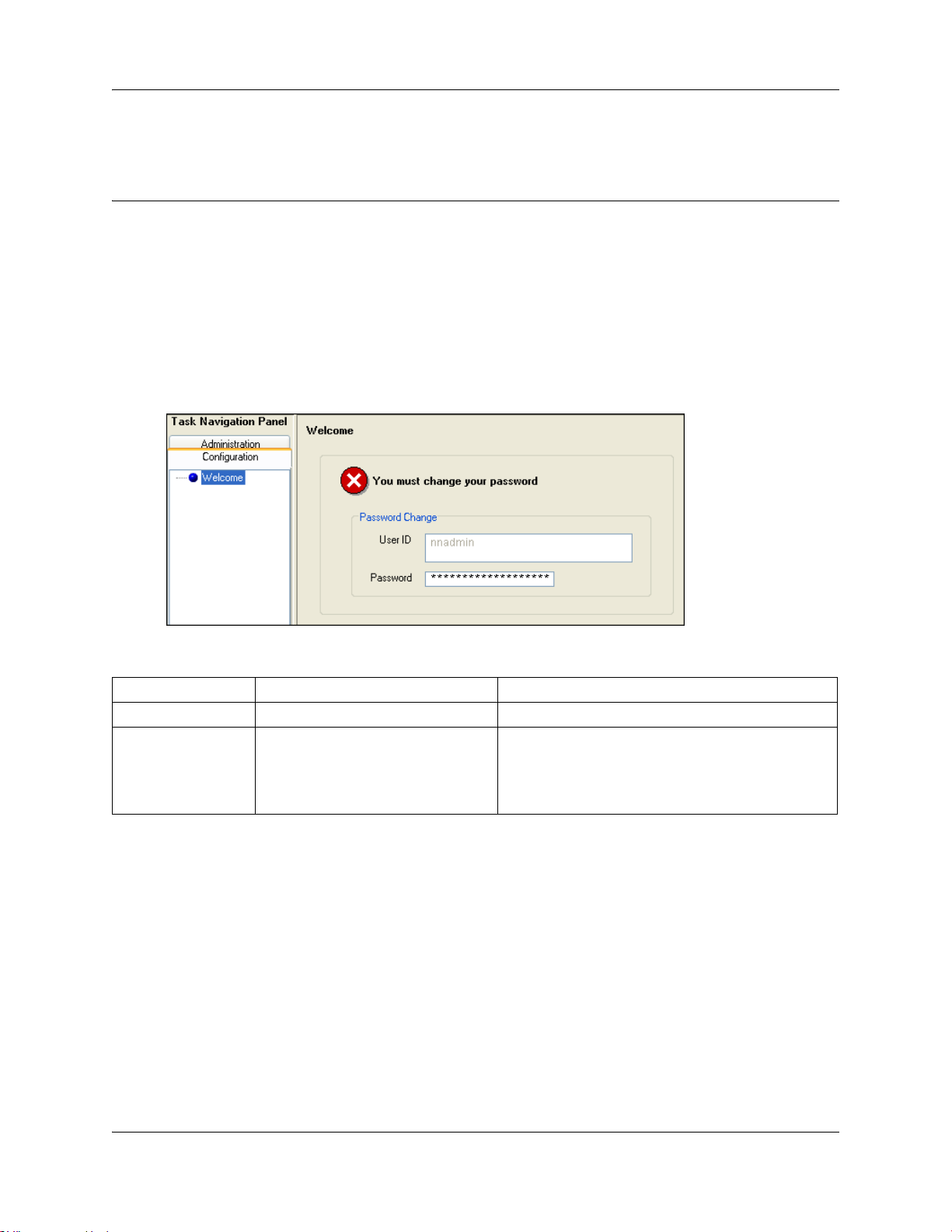
The Welcome panel displays information for the current account logged on the system. The
administrator is prompted to change the password before any programming menus are accessible.
This panel will be displayed:
• on the first login to the BCM by nnadmin,
• when the administrator has selected the forced password change option on an account, or
• if the password has expired.
Figure 1 Initial welcome panel
23
Table 2 Initial Welcome panel fields
Attribute Value Description
User ID <read-only> User ID you used to log on to the system.
Password <alphanumeric> To change password, select the field and enter new
Once the password has been changed the entire navigation tree is accessible. See Figure 2.
password. The password must satisfy the password
policy requirements for the system. See the
Administration Guide (NN40020-600) for more
information on password requirements.
Device Configuration Guide
Page 24
24 Chapter 2 Welcome panel
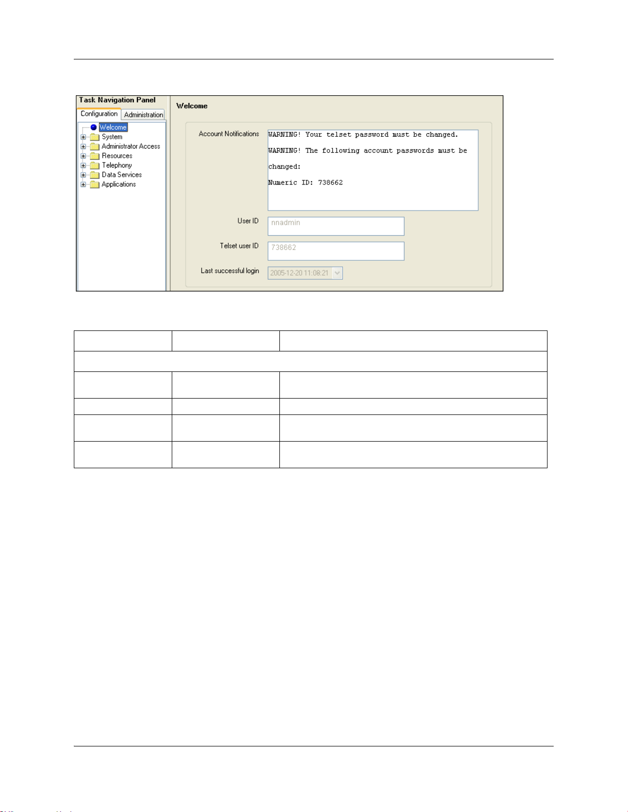
Figure 2 Welcome panel
Table 3 Welcome panel fields
Attribute Value Description
Current Account
Account Notifications <read-only> Displays BCM administrative messages or notifications
User ID <read-only> User ID you used to log on to the system.
Telset User ID <read-only> User ID used to logon to the telset configuration interfaces for
Last successful login <read-only> Date and time that this user account was last logged in the
regarding the current user.
telephony and CallPilot applications.
system.
NN40020-300NN40020-300
Page 25
Chapter 3
System Software
The system software identity.
The following path indicates where to access the system identification settings in Element
Manager:
• Element Manager: Configuration > System > Identification
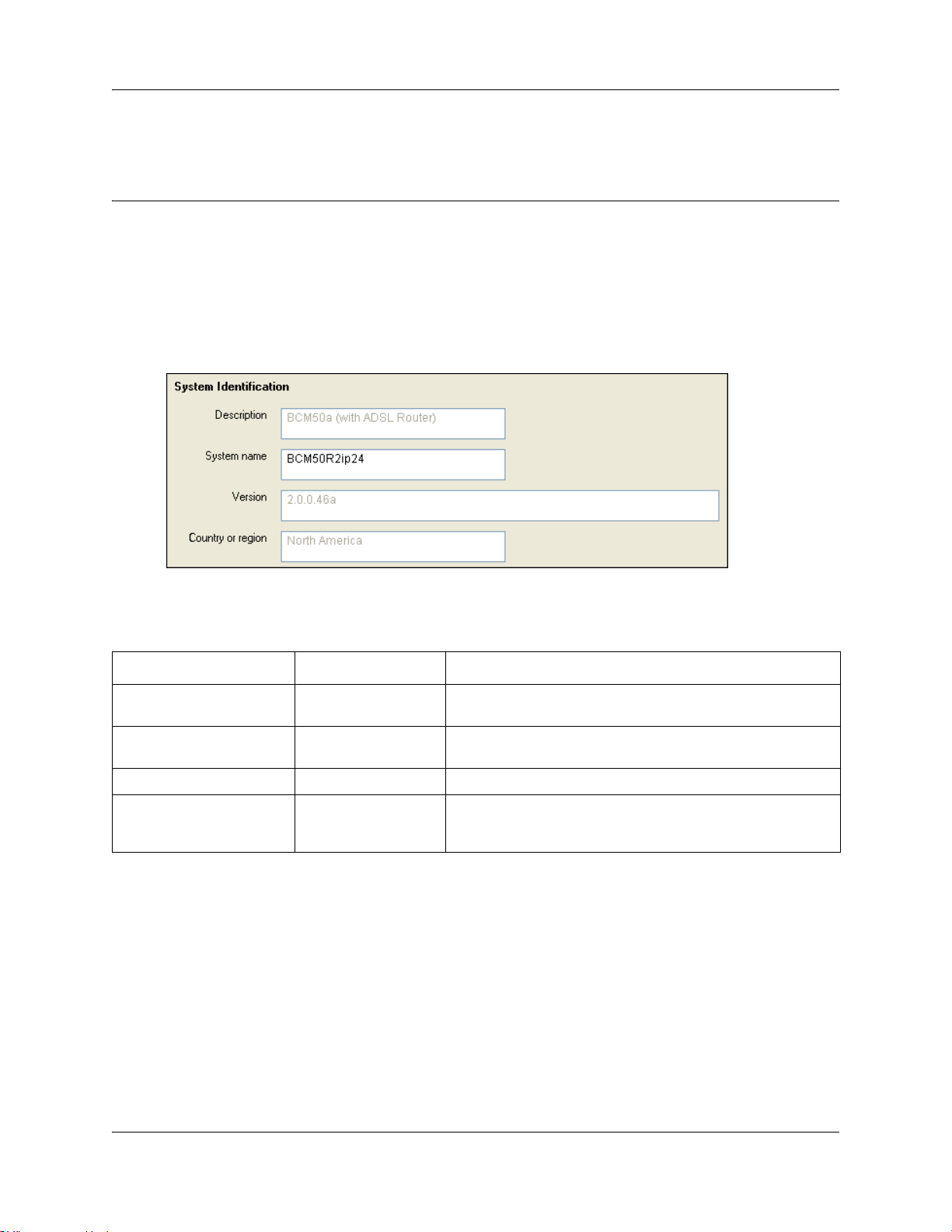
Figure 3 System Identification panel
25
Table 1 describes each field on this panel.
Table 1 System Identification fields
Attribute Value Description
Description <read-only> This is the system hardware release currently running on this
device.
System name <alphanumeric> It is easier to manage a group of systems if each system is
provided with a unique name or identification number.
Version <read-only> The version of software running on the BCM Main Unit.
Country or region <read-only> This setting defines internal system settings for default values,
available languages, and hardware and functional availability
for a specific country or region.
Setting Date and Time
How you set the Date and Time feature for your system depends on whether your system receives
this information from a network server.
The following path indicates where to access the date and time settings in Element Manager:
• Element Manager: Configuration > System > Date and Time
Device Configuration Guide
Page 26
26 Chapter 3 System Software
Click the following link to connect with the type of information you want to view:
Panel Task
Click the navigation tree heading to access general information about Date and Time management.
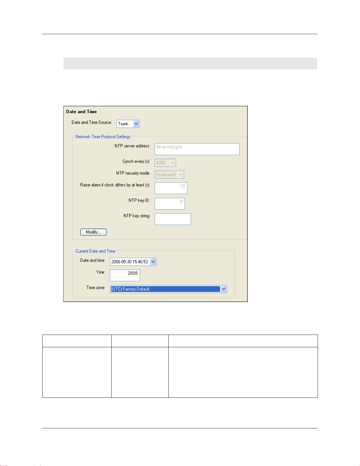
Figure 4 Date and time panel
“Setting clock control to local system” on page 28
Table 2 describes each field on the Date and Time panel.
Table 2 Date and Time panel fields (Sheet 1 of 2)
Attribute Value Description
Date and Time Source NTP
Tr un k
Manual
NN40020-300NN40020-300
Set to NTP (Network Time Protocol) if the system uses a
network server to determine the correct time and date.
Set to Trunk to use time and date settings from a CO through
an analog or IDSN line.
Set to Manual if you want to be able to manually configure the
time and date for your system.
Default: Manual
Page 27

Chapter 3 System Software 27
Table 2 Date and Time panel fields (Sheet 2 of 2)
Attribute Value Description
Network Time Protocol Settings
(Settings are active only if Clock Control Type is set to Network Time Protocol.)
NTP server address <IP address> The IP address of the server that controls the network time and
date.
Synch every (s) NA (not applicable)
1-XXXX
The number of seconds specified to elapse between contacts
with the NTP server.
1-XXXX: Number of seconds between contacts with the NTP
server.
NTP security mode Secured
Unsecured
Raise alarm if clock differs
by at least (s)
NTP key ID <1-65,534> ID for accessing the NTP.
NTP key string <8 characters> Control key corresponding to ID for accessing the NTP.
Current Date and Time
Date and time <country/
Year <numeric> The current year in yyyy format.
Time zone <drop-down list> The appropriate time zone for the location of this system. The
Daylight Savings Time <read-only> The appropriate mode for the Time zone.
<seconds> The number of discrepancy seconds specified that must occur
region-specific date
and time format>
Select whether the NTP security mode is secured or
unsecured.
before the system notifies you of a time difference from the
NTP server, if the system automatically checks with the NTP
server.
The current date and time.
Time zone must be set for software updates to be applied.
Selected: The system automatically updates the time twice a
year.
Cleared: The system never updates the time for Daylight
Savings Time.
Note: North American Daylight Savings Time rules change in 2007.
Four time zones have been added to support regions that do not want to
switch to the new time zone rules. The time zones are identified
“pre-2007 DST”.
If the system is to synchronize with an NTP Server or trunk, check the following:
1 Set Date and Time Source to NTP or Trunk.
2 In the NTP server address field enter the IP address of the NTP server.
3 Set the number of seconds between synchronizations in normal operations (Synch Every).
Device Configuration Guide
Page 28

28 Chapter 3 System Software
4 In the bottom frame, ensure that the Time zone is correct for the location of the local system.
5 If Trunk was selected in the Date and Time Source drop-down list, enter the year in the Year
field.
Note: Only time and date info are updated when NTP and Trunk
settings are selected. Year information is not updated. Y ou also have full
control over time and date settings using telset admin even if NTP or
Trunk are selected. Any setting applied through telset admin are
over-written by the external source if NTP or Trunk are selected. Time
zones need to be set for software updates to be applied.
Setting clock control to local system
If you want the clock to be controlled locally:
1 Ensure that Date and Time Source is set to Manual.
2 In the bottom frame:
•In the Time z one field, select the Time zone the system uses.
•In the Date and time field, enter the month, day and year, hours and minutes and time of
day.
•The Daylight Savings Time check box is selected or cleared automatically, depending on
the time zone selected.
NN40020-300NN40020-300
Page 29

Chapter 4
System schedule settings and services scheduling
Use scheduled services to control how calls are answered in off-hours (Ringing Groups), how calls
are routed at various times of the day, and how restrictions are applied on lines and telephones at
specific times of the day.
The following paths indicate where to access scheduled services in Element Manager and through
Telset Administration:
• Element Manager: Configuration > Telephony > Scheduled Services
• Telset interface: **CONFIG > Services
The Scheduled Services - Settings and Schedules panel has three distinct areas for configuration.
• The table in the top frame allows you to determine which schedules are active for the system
for routing, restriction, and ringing schedules.
• The table in the top frame to the right sets the time periods within each schedule for each day
of the week.
• The table in the bottom frame allows you to rename schedules.
29
Click one of the following links to connect with the type of information you want to view:
Panels Related panels or tasks Feature
“Configuring scheduled service”
on page 31
“Configuring schedule names and
timers” on page 30
Click the navigation tree heading to access general information about Ring Group management.
Alternate routes for routing
schedules in the Networking
Configuration Guide
(NN40020-603)
“Ring Groups - Line Settings” on
page 99
Restriction filters in the Networking
Configuration Guide
(NN40020-603)
“Restrictions (Line and Remote) in
the Networking Configuration Guide
(NN40020-603)
“Restrictions main tab” on page 65
Class of Service table in the
Networking Configuration Guide
(NN40020-603)
“Control telephone” on page 229
Schedules are activated and deactivated through control telephones. Refer to “Control telephone”
on page 229.
Device Configuration Guide
Page 30
30 Chapter 4 System schedule settings and services scheduling
Restriction and Routing services require a service control password before users are allowed to
change scheduling on a control telephone. The Service Contro l Password field on this panel allows
you to delete a current entry, and add a new password. Make a note of the password; the panel
displays only asterisks.
Configuring schedule names and timers
The tables on this panel allow you to change the names of the schedules, and to determine when
the schedules, which are set to automatically execute, are deployed. Any changes to these settings
affect all services that use schedules.
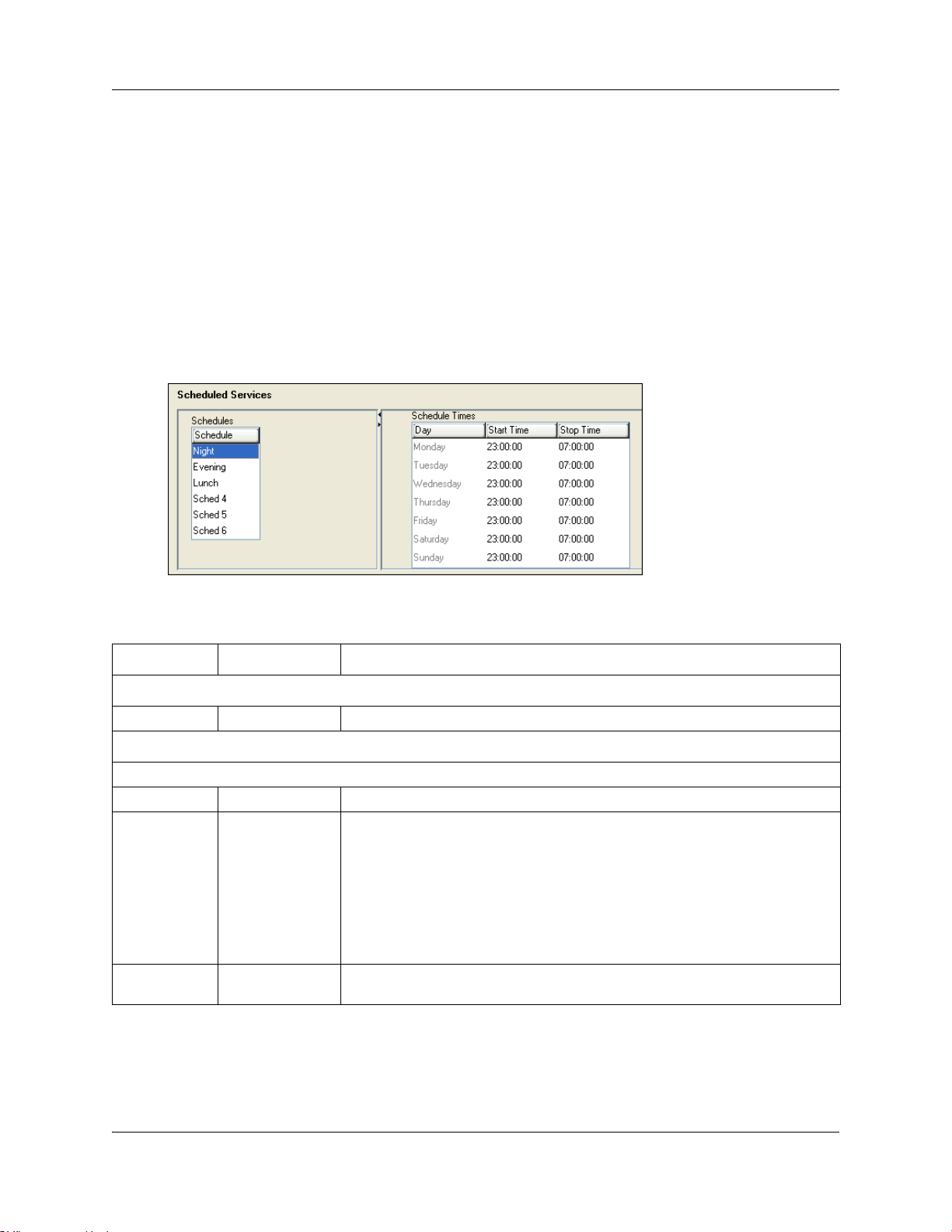
Figure 5 Schedule names and timers
Table 3 describes the fields on the subpanel tables.
Table 3 Schedule common settings
Attribute Value Description
Schedules
Schedule <alphanumeric> Double-click the field, and enter a descriptive name for the schedule.
Schedule Times
For each schedule, there are timers for the seven days of the week.
Day <seven days>
Start Time 00:00 to 12:00
a.m.-p.m./24:00
Stop Time 00:00 to 12:00
a.m.-p.m./24:00
This is the time when the schedule starts, and any previously-running schedules
stop.
Use a 12-hour or 24-hour format. If the entry is less than 12:00, the system
prompts for a day period setting.
00:00 = schedule is off
start and stop are the same = schedule runs for 24 hours
start: 22:00/stop: 06:00 = schedule starts at midnight, runs until 6 a.m., then
starts again at 10 p.m. (22:00).
This is the time when the schedule stops.
NN40020-300NN40020-300
Page 31

Chapter 4 System schedule settings and services scheduling 31
Default time settings
Table 4 provides a list of the default times for each schedule.
Table 4 Default schedule times
Schedule Start Time Stop Time Schedule Start Time Stop Time
Schedule 1: Night 23:00 07:00 Schedule 4: 00:00 00:00
Schedule 2: Evening 17:00 23:00
Schedule 3: Lunch 12:00 13:00 Schedule 6: 00:00 00:00
Configuring scheduled service
The table in the top frame lists all schedules available on the system. Configure the settings for the
schedules that you are using for your system.
Figure 6 Services table
Schedule 5: 00:00 00:00
Table 5 describes the fields under Scheduled Services.
Table 5 Service settings (Sheet 1 of 2)
Attribute Value Description
Service control
password
<alphanumeric> Restriction and Routing schedules require the user to enter a password on the
control telephone before scheduling can be changed.
If you forget the password, enter a new password.
Device Configuration Guide
Page 32

32 Chapter 4 System schedule settings and services scheduling
Table 5 Service settings (Sheet 2 of 2)
Attribute Value Description
Schedule <read-only> These are the schedules that are available on the system.
Routing Svc Off
Manual
Auto
Overflow <check box> If all the lines used by a route are busy when a call is made, you can program
Off prevents the service from being activated.
Manual allows you to turn the service on and off at any time from a control
telephone. This setting overrides any automatically-running schedules.
Auto allows you to program a stop and start time for a service under the
Common Settings heading. These times are then automatically executed when
the service is active.
Default: Off
Routing service to overflow to the route used for normal mode. If the call is
routed to use the normal mode, the telephone sounds a warning tone and
displays the message
call to avoid the toll charges or can continue.
Expensive route. The caller then can release the
Tips: A schedule must be active for overflow routing to be in effect. Overflow
routing is not available in normal mode.
You must create an overflow route to be used with each routing code. In this
way, every route used with a scheduled mode that has overflow service must
have an alternate route in normal service.
Default: Cleared
Ringing Svc Off
Manual
Auto
Trunk Answer <check box> Trunk answer allows you to answer, from any telephone, an external call that is
Extra Dial Set None
DN <XX>
DN <control set>
Restriction Svc Off
Manual
Auto
Off prevents the service from being activated.
Manual allows you to turn the service on and off at any time from a control
telephone. This setting overrides any automatically-running schedules.
Auto allows you to program a stop and start time for a service under the
Common Settings heading. These times are then executed automatically when
the service is active.
Default: Off
For details about setting up ring groups, refer to “Creating ring groups” on
page 97.
ringing at another telephone in your office, if the Ringing Service is active on that
line at the time of the call. If the service is not active, you cannot answer the call.
Trunk answer is useful if the other telephones are not assigned the same lines
as the telephone you are using to answer the call.
Note: You can change the Trunk Answer setting only if Ringing service is set to
Manual or Auto.
Default: Selected
The Extra dial set attribute allows you to assign an additional telephone to
receive calls for each schedule.
Note: The extra dial set is activated during a schedule by entering the Ringing
service feature code from the assigned direct dial telephone. This does not
activate the Ringing service, unless the direct dial telephone is also a control
set.
Off prevents the service from being activated.
Manual allows you to turn the service on and off at any time from a control
telephone. This setting overrides any automatically-running schedules.
Auto allows you to program a stop and start time for a service under the
Common Settings heading. These times are then executed automatically when
the service is active.
Default: Off
NN40020-300NN40020-300
Page 33

Chapter 5
System features and feature codes
• “BCM feature codes” on page 33 provides a complete list of the feature codes that can be
accessed from digital and IP telephones.
• “Button programming features” on page 36 provides a list of the features that are
programmable under the DN record Button Programming heading.
BCM feature codes
The following provides a quick reference for BCM features available by pressing the FEATURE
button on M-series telephones, Business Series Terminals (BST series), and IP telephones. Table 6
provides feature names sorted alphabetically, and numerically by feature code.
Refer to the user documentation for the specific product to find out how to use the codes on each
type of telephone.
33
Table 6 Features sorted by feature name and by activation code (Sheet 1 of 4)
Sorted by feature name Sorted by activation code
FEATURE
Feature name
Alarm time (room set) 875
Alarm time - Cancel #875 *0 Button inquiry
Alarm time (HS admin set) 877
Autodial - External *1 #1 Messages - Cancel Send
Autodial - Internal *2
Auto Hold 73 2 Ring Again
Auto Hold - Cancel #73
Background Music 86 *2 Autodial - Internal
Background Music - Cancel #86
Button inquiry *0 *3 Memory buttons - Program
Contact Center agent login/log out 904
Contact Center agent make busy/ready 908 #4 Call Forward - Cancel
Contact Center queue status 909
Call Charge Indication 818 5 Last Number Redial
Call Duration Timer 77
Call Forward 4 *502 Language - Alternate
Call Forward - Cancel #4
Call Forward to Voice Mail 984 *504 Language - Alternate 3
Call Information 811
<code>
FEATURE
<code>
0 Speed Dial - Activate
1 Messages - Send
*1 Autodial - External
#2 Ring Again - Cancel
3 Conference Call
4 Call Forward
*4 Speed Dial - Add, change
*501 Language - Primary
*503 Language - Alternate 2
*510 Time zone readjust (IP telephones)
Feature name
Device Configuration Guide
Page 34

34 Chapter 5 System features and feature codes
Table 6 Features sorted by feature name and by activation code (Sheet 2 of 4)
Sorted by feature name Sorted by activation code
FEATURE
Feature name
Call Log - Delete items (autobumping) 815
Call Log - Manual 813
Call Log - View information 812 *537 Find oldest SWCA
Call Log options *84 *538 Find newest SWCA
Call Log password *85
Call Park 74 *6 Ring Type
Call Queuing 801
Camp-on 82 61 Page - Internal (telephone speakers)
Class of Service 68
Conference Call 3 63
Contrast adjustment *7 64 Line Pool
Contact Center agent login/log out 904 65 Messages - View
Contact Center Supervise 905
Contact Center Supervisor Help 906 67 Saved Number Redial
Dialing Mode *82
Directed Pickup 76 69 Priority Call
Display Voice Mail DN, skillset or IVR DN 985
Do not Disturb 85 70 Transfer
Do not Disturb - Cancel #85
Exclusive Hold 79 71 Link
Voice Mail Leave Message 980
Group Listening 802 #73 Auto Hold - Cancel
Group Listening - Cancel #802
Group Pickup 75 75 Group Pickup
IP Services list *900
IP Hot desking *999 77 Call Duration Timer
Language - Primary *501
Language - Alternate *502 79 Exclusive Hold
Language - Alternate 2 *503
Language - Alternate 3 *504 *81 Line buttons - Move
Last Number Redial 5
Line buttons - Move *81 *82 Dialing Mode
Line Pool 64
Line Redirection 84 84 Line Redirection
Line Redirection - Cancel #84
Link 71 *84 Call Log options
Long tones 808
<code>
FEATURE
<code>
*521 to *536
*550 Silent Monitor
60 Page
62 Page - External (external speakers)
66 Voice Call
68 Class of Service
*7 Contrast adjustment
#70 Transfer - Cancel
73 Auto Hold
74 Call Park
76 Directed Pickup
78 Pause
*80 Ring Volume
82 Camp-on
83 Privacy (on/off)
#84 Line Redirection - Cancel
85 Do not Disturb
Feature name
System Wide Call Appearance
(SWCA)
Page - Combined (internal and
external)
NN40020-300NN40020-300
Page 35

Chapter 5 System features and feature codes 35
Table 6 Features sorted by feature name and by activation code (Sheet 3 of 4)
Sorted by feature name Sorted by activation code
Feature name
FEATURE
<code>
FEATURE
<code>
Feature name
Malicious call identification (MCID) 897 #85 Do not Disturb - Cancel
Memory buttons - Program *3 *85 Call Log password
Messages - Send 1
86 Background Music
Messages - Cancel Send #1 #86 Background Music - Cancel
Messages - View 65
88 Voice Call Deny
Name and number blocking 819 #88 Cancel Voice Call Deny
Name and number blocking - Cancel #819
800 Trunk Answer
Page 60 801 Call Queuing
Page - Combined (internal and external) 63
802 Group Listening
Page - External (external speakers) 62 #802 Group Listening - Cancel
Page - Internal (telephone speakers) 61
803 Time
Pause 78 804 Wait for dial tone
Priority Call 69
805 Test telephone display
Privacy (on/off) 83 806 Static Time
Record call 989
#806 Static Time - Cancel
Ring Again 2 807 Ringing (Signal) Call
Ring Again - Cancel #2
808 Long tones
Ring Type *6 811 Call Information
Ring Volume *80
812 Call Log - View information
Ringing (Signal) Call 807 813 Call Log - Manual
Room condition (Room set) 876
815
Call Log - Delete items
(autobumping)
Room condition (HS admin set) 878 818 Call Charge Indication
Room occupancy 879
819 Name and number blocking
Run/Stop *9 #819 Name and number blocking - Cancel
Saved Number Redial 67
870 View active services
Silent Monitor *550 871 Turn Ringing service on
Speed Dial - Add, change *4
#871 Turn Ringing service off
Speed Dial - Activate 0 872 Turn Restriction service on
Static Time 806
Static Time - Cancel #806 873 Turn Routing service on
System Wide Call Appearance (SWCA) *521 to
*536
Find available SWCA *520
#872 Turn Restriction service off
1
#873 Turn Routing service off
875 Alarm time
#875 Alarm time - Cancel
Find oldest SWCA *537 876 Room condition (Room set)
Find newest SWCA *538 877 Alarm time (HS admin)
Test telephone display 805
878 Room condition (HS admin)
Time 803 879 Room occupancy
Device Configuration Guide
Page 36

36 Chapter 5 System features and feature codes
Table 6 Features sorted by feature name and by activation code (Sheet 4 of 4)
Sorted by feature name Sorted by activation code
FEATURE
Feature name
Time zone adjust (IP telephones) *510 897 Malicious call identification (MCID)
Transfer 70 *9 Run/Stop
Transfer - Cancel #70
Transfer to mailbox 986 904 Contact Center agent login/log out
Trunk Answer 800
Turn Restriction service off #872 906 Contact Center Supervisor Help
Turn Restriction service on 872
Turn Ringing service off #871 908 Contact Center agent make busy/
Turn Ringing service on 871 909 Contact Center queue status
Turn Routing service off #873 980 Voice Mail Leave Message
Turn Routing service on
View active services 870 982 Voice Mail Operator settings
Voice Call 66
Voice Call Deny 88 985 Display Voice Mail DN, skillset, or
Voice Call Deny - Cancel #88
Voice Mail direct 988 986 Transfer to mailbox
Voice Mail Interrupt 987
Voice Mail login 981 988 Voice Mail direct
Voice Mail Operator settings 982
Wait for dial tone 804 *999 IP Hot desking
Note
1
Contact your System Administrator for the service control password.
1
<code>
873 981 Voice Mail login
FEATURE
<code>
*900 IP Services list
905 Contact Center Supervise
907 Contact Center Activity Code
984 Call Forward to Voice Mail
987 Voice Mail Interrupt
989 Record call
Feature name
ready
IVR DN
Button programming features
The following describes the features available for Button Programming (Configuration >
Telephony > Sets > All DNs > Capabilities and Preferences > Button Programming).
Note that some of these features require other system settings in order to work.
• Some of the buttons are controlled by features under Configuration > Telephony > Sets > All
DNs > Capabilities and Preferences > Capabilities tab (bottom panel). Pagin g is an example
of a feature that requires other settings.
NN40020-300NN40020-300
Page 37

Chapter 5 System features and feature codes 37
• Some features also require that the service be available on the line from your telephone service
provider. The types of lines provided are also determined by the region chosen for your
system. MCID (malicious call identification) is an example of this type of feature.
Table 7 Button Programming Feature settings (Sheet 1 of 4)
Set command
(FEATURE
<code>)
Feature Description
None Indicates a button that is configured for button programming, but nothing
0 Speed dial Activates the speed dial feature. The telephone prompts the user for a
1 Send message Allows the user to send a message to another DN on the system.
#1 Cancel send message Allows the user to cancel a message that was sent to another set within
2 Ring again Turns on the Ring again feature.
3 Conference/Transfer Initiates a conference between user and two parties.
4 Call forward Allows the user to enter a number to forward all calls.
5 Last number redial Causes set to redial the last number that was dialed.
*5 Language choice Allows the user to select the language in which prompts are displayed.
60 Page - general Initiates a page.
61 Page - Internal Allows the user to page internal to a specific zone, which is identified
62 Page - External Allows the user to page through the speaker on a specific telephone.
63 Page - speaker and zone Allows the user to page through both the internal sets, and externally
64 Line pool Allows the user to access a line pool. The pool this button accesses is
65 Reply message Allows the user to access messages, and send a reply to the message
#65 Cancel message waiting Allows the user to cancel the message waiting indicator.
66 Voice call Allows the user to make an announcement, or begin a call through the
67 Saved number redial Allows the user to redial a number that was saved while on a call.
68 Restriction override Allows the user to override any restrictions on the set or line with a CoS
69 Priority call Allows the user to priority call an internal DN that is currently busy.
*7 Contrast Allows the user to adjust the contrast of the display screen.
70 Transfer Allows the user to transfer an existing call to another telephone or
has been entered.
speed dial code.
the network.
Note: Allow redirect must be selected to forward calls outside of the
system.
within the Button programming. (For example F611 internal zone 1, F610
page internal all zones.)
connected paging equipment to a specific zone, which is identified within
Button programming.
specified during Button Programming for this feature.
sender.
speaker of another telephone.
password.
external number.
Device Configuration Guide
Page 38

38 Chapter 5 System features and feature codes
Table 7 Button Programming Feature settings (Sheet 2 of 4)
Set command
(FEATURE
<code>)
71 Link Activates the Link command, which allows the user to access special
74 Call park Allows the user to park a call.
*520 Find available SWCA key System searches for a free SWCA key among the SWCA keys that are
*521 to *536 System Wide Call
*537 Find oldest SWCA call System searches among the SWCA keys assigned to the telephone, and
*538 Find newest SWCA call System searches among the SWCA keys assigned to the telephone, and
*550 Silent monitor Allows the user to monitor hunt group calls. (Telephone must be
75 Group pickup Allows the user to answer a call ringing telephone within the Pickup
76 Directed pickup Allows the user to answer any ringing telephone within the same system.
77 Call timer Allows the user to see the call duration timer.
78 Pause Allows the user to insert a pause during a dialing sequence.
79 Exclusive hold Allows the user to place a call on hold at the current telephone. All
800 Trunk answer Allows the user to answer a ringing line while in a ringing service. (If
801 Call queuing Allows the user to answer calls in order when several calls arrive in rapid
802 Group listening Activates the speaker on the set to allow a group of people to hear a call.
803 Time Briefly displays the current time.
804 Wait for dialtone Places a pause in a dialing string that holds the following digits until a
806 Static date and time First line displays the date and time.
807 Ringing (Signal) call Directly rings another telephone inside the system when an extension is
808 Long tones Allows the user to send long DTMF tones.
811 Call information Allows the user to view information about a current call.
812 Call log - view
813 Call LogIt Allows the user to add the current call to the call log manually.
Feature Description
features on a remote PBX system.
assigned to the current telephone.
Non-intercom calls are associated with an available SWCA key when the
Appearance (1 to 16)
information
call is answered, originated, or placed on Hold.
Features that interact with this feature: Hold, telephone keys, outgoing
and incoming calls.
unparks the call that has been parked the longest.
unparks the most recently parked call.
assigned with SM supervisor.)
group.
appearances of the call on other telephones indicate the line is busy.
enabled).
succession. Calls are presented in this order: incoming calls, timed-out
forwarded calls, then camped calls.
But the user must talk to the caller through the handset.
dialtone is perceived on the line.
entered after the feature is selected. This is the same process as
pressing an intercom button and dialing an extension.
Allows the user to view call log information.
NN40020-300NN40020-300
Page 39

Chapter 5 System features and feature codes 39
Table 7 Button Programming Feature settings (Sheet 3 of 4)
Set command
(FEATURE
<code>)
815 Call logs autobumping Allows the user to select if the system will remove the oldest log item
818 Call charge indication Allows the user to view the charges for a call (available on DASS2 and
819 ONN blocking Allows the user to block the call information from the telephone for an
82 Camp-on Allows the user to transfer and camp an external call on another
83 Privacy control Allows the user to change the line privacy setting on the current call.
84 Line redirection Allows the user to redirect a line on their telephone to an external
85 Do not disturb Allows the user to block incoming calls from ringing on the telephone.
86 Background music Allows the user to play music provided by a background music source
870 Service mode status Allows the user to view the current service mode being used.
871 Ringing service Allows the user to change the ringing service mode.
872 Restriction service Allows the user to change the restriction service mode.
873 Routing Service Allows the user to change the routing service mode.
88 Voice call deny Allows the user to deny other users from Voice Calling their set.
897 MCID (Malicious Call Identification)
*501 Language choice Provides a menu that allows you to choose the language for the display
*7 Contrast Digital telephones only.
904 CC agent login/log out Allows the user to log in or out of ACD.
905 CC supervise Allows the CC supervisor to monitor CC agent calls.
906 CC supervisor help Allows the CC agent to request help from a CC supervisor.
907 CC activity code Allows the CC agent or supervisor to enter activity codes for reporting.
908 CC agent make Not
909 CC skillset status Allows the user to view the status of queued calls on ACD.
980 Voice mail Leave
Feature Description
manually when the log space fills.
ETSI Euro trunks only).
outgoing call.
telephone in the system.
number.
through the speaker on the telephone.
If this feature is invoked manually and normal ringing is selected, the
service will be deactivated and will override any automatically-running
services.
You must select Normal until * to cancel the services temporarily. This
will allow the service to activate at night as programmed.
Allows the user to query the system for information about a call within 25
seconds after the user hangs up, but before the caller hangs up.
prompts on the telephone.
Sets the level of contrast for the telephone display.
Allows the user to indicate ready or Not ready status on ACD.
ready/ready
Allows the user to log into voice mail box to leave a message.
Message
Device Configuration Guide
Page 40

40 Chapter 5 System features and feature codes
Table 7 Button Programming Feature settings (Sheet 4 of 4)
Set command
(FEATURE
<code>)
981 Voice mail login Opens your mailbox to play your messages and to access mailbox
982 Voice mail operator
984 Call forward to voice mail Forwards all calls to your voice mail.
985 Display voice mail DN Displays the voice mail, skillset, or IVR DN.
986 Transfer to mailbox Transfers an external call directly to a mailbox on the CallPilot system.
987 Voice mail interrupt Intercepts a caller who is listening to your mailbox greeting or leaving a
988 Voice mail direct Dial an internal user via the name in the voice mail directory.
989 Record call Record the call to your voice mail box. Must be enabled by the system
*900 IP services list IP telephones only.
*999 IP Hot desking IP telephones only.
Feature Description
options.
Allows the user to set the parameters for the voice mail operator.
settings
message.
administrator.
Allows the user to access a feature menu. This is the same menu that is
accessed by pressing the Services key.
Allows the user to access the Hot desking feature. This feature allows
calls to be diverted from one IP telephone to another.
NN40020-300NN40020-300
Page 41

Chapter 6
DN records parameters
The DN record defines the specific function of each telephone within the system.
The following paths indicate where to access DN record parameters in Element Manager and
through Telset Administration:
• Element Manager: Configuration > Telephony > Sets > All DNs
• Telset interface: **CONFIG>Terminals and Sets
Other areas of programming that affect how each telephone functions include:
• system settings (“Global telephony settings” on page 73)
• telephone model
The DN records panel is a multilayered panel with multiple tabs. Although all panels show up for
all models, not all models require configuration for all panels. Refer to the task and feature
programming links to determine specific configuration.
41
The panel tabs links provide a general description of each panel and definitions of each panel field.
Click one of the following links to connect with the type of information you want to view:
Panel tabs Tasks Features
“Main panel tabs: common fields” on
page 42
“Line Access tab” on page 43 “Configuring telephones: Digital
“Line Assignment tab” on
page 46
“Line Pool Access tab” on
page 48
“Answer DNs tab” on page 49 “Supervisor telephone for silent
“Capabilities and Preferences main
tab” on page 50
“Capabilities tab” on page 52
“SWCA Call Group tab” on
page 54
“Preferences tab” on page 55 “Features to set up telephone
“Common procedures: copying
and renumbering DNs” on
page 69
telephones” on page 123
“Feature configuration:
Answering calls” on page 197
“Feature configuration: Making
calls” on page 217
“Hotline telephone” on page 229
“Control telephone” on page 229
monitoring” on page 230
set features” on page 191
“Auxiliary ringer” on page 194
“ATA Settings tab” on page 57
Device Configuration Guide
Page 42

42 Chapter 6 DN records parameters
Panel tabs Tasks Features
“IP Terminal Details tab” on
page 59
“Button Programming table”
on page 60
“Button Programming tab” on
page 60 (includes CAP/KIM
button programming)
“User Speed Dial tab” on
page 63
“Restrictions main tab” on page 65
“Set Restrictions tab” on
page 66
“Line/Set Restrictions tab” on
page 67
Click the navigation tree heading to access general information about DN records.
“Configuring telephones: IP
telephones” on page 139
“Global VoIP features” on
page 143
“Default memory button
programming for telephones” on
page 153
“Creating an enhanced CAP
station” on page 233
“System features and feature
codes” on page 33
“Restrictions (Line and Remote)”
in the Networking Configuration
Guide (NN40020-603)
Main panel tabs: common fields
All main panel tabs display the same first three columns listed in Table 8.
Table 8 Common columns for the main tabs (Sheet 1 of 2)
Attribute Value Description
DN <numeric> This number is unique to each telephone record. The number
identifies the telephone to the system. DN start digits and DN
length are configured during system setup.
Digital and analog telephone DNs map one-to-one with ports
on module connections. IP telephone DNs do not map to
specific ports; however, a keycode is required to activate the
feature.
NN40020-300NN40020-300
Page 43

Table 8 Common columns for the main tabs (Sheet 2 of 2)
Attribute Value Description
Model
Name <up to seven
Analog
7000
7100
7208
7310/7316
7316E
7324
2004
2002
2001
2007
2033
2050
DMC prtb
2210/2211/2212
1120E, 1140E
Doophone
alphanumeric characters>
This heading appears for telephones in the digital DN range,
from the Start DN (default: 221) up to DN 433. Choose the
setting that is appropriate for the telephone you want to
configure.
This field is read-only if the telephone is already attached or
registered to the system.
• 7310/7316: also 7406 cordless digital phone
• 7316E: also for 7316E digital phone with KIMs
(Model 7000 phones are supported in Europe only)
Use this field to provide a more specific description of the
telephone, such as the last name of the user, the location, or
the actual extension number if it is different than the DN
number.
Also refer to “Programming name display (outgoing)” in the
Networking Configuration Guide (NN40020-603).
Chapter 6 DN records parameters 43
Line Access tab
The Line Access tab displays the System DNs table. Line access programming is performed using
the three tabs in the bottom panel. Refer to Figure 7.
Device Configuration Guide
Page 44

44 Chapter 6 DN records parameters
Figure 7 System DNs table
Table 9 describes these fields.
Table 9 Line Access - System DNs table fields (Sheet 1 of 2)
Attribute Value Description
DN <read-only> Refer to “Main panel tabs: common fields” on page 42.
Model <alphanumeric> Refer to “Main panel tabs: common fields” on page 42.
Name <alphanumeric> Refer to “Main panel tabs: common fields” on page 42.
Port <port number> This number indicates the port number to which this DN
corresponds.
A group of port numbers relates to a specific station module
installed in your BCM. If you change the DN for a telephone,
the port number remains the same.
If you physically move a telephone with the relocation feature
turned on, the DN transfers to the new port, and the DN for
that port transfers to the vacated location.
Pub. OLI <
up to 12 digits> This setting defaults to the DN of the device. The Public
Network Code concatenates to the beginning of this number
to create the entire public network number. The length of this
number is dependent on the country requirements.
This line identification number (OLI) appears on the
telephone called from this telephone over the public network.
Also refer to “Public network settings” in the Networking
Configuration Guide (NN40020-603).
North America: If the OLI contains the public network code,
the information in the Public Network code field is ignored.
Therefore, it is recommended that OLIs be programmed to
the public received number length, only. This allows a global
change if the Public Network Code is changed.
Also refer to “Configuring CLID on your system” in the
Networking Configuration Guide (NN40020-603).
NN40020-300NN40020-300
Page 45

Chapter 6 DN records parameters 45
Table 9 Line Access - System DNs table fields (Sheet 2 of 2)
Attribute Value Description
Priv. OLI <numeric> Define the originating line identification number (OLI) that
appears on the telephone being called from this telephone
over a private network.
Note: On systems running DID, this field is populated
automatically with the DN.
On PBX systems, this field is populated automatically only if
the DN length and the Received # length are the same.
If the DN length or the Received # length are changed to be
different from each other, this field is cleared.
Also refer to “Configuring CLID on your system” in the
Networking Configuration Guide (NN40020-603).
*If your system allows outgoing name and number blocking, the telephone must have a valid OLI.
Fwd No
Answer
up to 24 digits Enter the number to which you want to redirect unanswered
incoming calls.
Fwd Delay 2, 3, 4, 6, 10 Define the number of rings before the system forwards an
unanswered call.
This heading only appears after you enter a Call Forward No
Answer number and press Enter.
Default: 4
Fwd Busy up to 24 digits Redirect incoming calls when this telephone is busy with
another call.
Fwd All up to 24 digits This setting is the same as using FEATURE 4 at a telephone.
When this feature is active, all calls to this telephone are
forwarded to the destination entered in this field.
If you are forwarding calls to a remote location, ensure that
you include the required destination/access codes.
A user can press FEATURE #4 to cancel this feature.
Device Configuration Guide
Page 46

46 Chapter 6 DN records parameters
Line Assignment tab
The line assignment setting allows you to assign physical trunks and target lines to each telephone.
Target lines are used as incoming only. Other lines can be used to both place and answer calls, if
they are configured to do so.
Figure 8 Line Assignment tabbed panel - Assigned Lines table
Table 10 describes the fields on this panel.
Table 10 Telephone line assignment fields (Sheet 1 of 3)
Attribute Values Description
Line <read-only> These are the lines on which this telephone can receive calls.
If the line is a two-way line (DID), the user can also use the
line to make calls.
Also refer to “Configuring Lines” in the Networking
Configuration Guide (NN40020-603).
Appearance Type Ring only,
Appr&Ring, Appr
only
Appearances
(for target lines,
only)
<1-10> Select the number of appearances of a target line.
Select how a call on this line appears on the telephone.
If you choose Appr&Ring or Appr only, you can have as many
simultaneous DID calls as there are target line button
appearances.
If you choose Ring only, you can have as many simultaneous
DID calls as you have intercom buttons.
Note: The BCM50 2.0 does not support a mixture of Appr
only and Ring only appearances for the same line.
7000 or 7100 digital phones default to Ring only.
(Model 7000 phones are supported in Europe only)
Note: The number of appearances that can be assigned to a
telephone depends on how many buttons with indicators are
available. Target line appearances cannot overwrite other
line appearances, Answer DNs, Intercom buttons, or
assigned Handsfree button.
NN40020-300NN40020-300
Page 47

Chapter 6 DN records parameters 47
Table 10 Telephone line assignment fields (Sheet 2 of 3)
Attribute Values Description
Caller ID set <check box> This prompt only appears for target lines, and for any analog
lines that provide CLID through a GATM (not all markets).
When enabled, the telephone displays call information when
it is available for a call before answer.
When disabled, no call information is displayed for this line.
Choose this setting if the telephone does not have a display,
or if you do not want call information displayed to the user.
Disabling this function can reduce system resource
requirements.
Limitation: Only 30 telephones can have this field enabled
for any given line.
Vmsg Set <check box> Select whether an indicator shows on the telephone for a
voice message waiting on an external voice message
system.
The line must appear on the receiving telephone.
Note: The Message Waiting Indicator (MWI) is currently
supported exclusively by Meridian Mail and CallPilot and
SL-100, and DMS-100.
MCDN note: If your system is part of an MCDN network
connected to a Meridian 1 system, and you are using the
voice mail system off the Meridian 1, you must enable this
field.
Analog lines connected to legacy analog ASM station
modules, and analog telephones attached to an ATA device,
do not provide visible message waiting indication. Analog
telephones connected to a GASM8 support message
indicators, if the telephone is set up to receive them.
Note: Contact your voice message service provider to find out if your voice
message service works with BCM50 2.0, or if you have any problems with your
service.
Priv. Received #
(Target lines only)
Pub. Received #
(Target lines only)
Actions
Add To add a line to a telephone:
These fields reflect the settings defined under target lines.
These are the digit strings that the system uses to identify a call for this telephone.
Refer to “Trunk/Line Data, main panel” in the Networking Configuration Guide
(NN40020-603).
1. On the System DNs table (Line Access tab), choose the DN record where you
want to add lines.
2. Under the Assigned Lines table in the bottom panel, click Add.
3. Enter a line number in the dialog box.
4. Click OK to save the line to the list.
Device Configuration Guide
Page 48

48 Chapter 6 DN records parameters
Table 10 Telephone line assignment fields (Sheet 3 of 3)
Attribute Values Description
Delete To delete a line from a telephone:
1. On the System DNs table (Line access tab), choose the DN record where you
want to delete lines.
2. On the Assigned Lines table in the bottom panel, select a line you want to delete.
3. Click Delete.
4. Click OK to confirm the selection.
Line Pool Access tab
Use the Line Pool Access tab to add line pools to a telephone record.
Figure 9 Line Pool Access tab
These shared pools of lines allow many users to use fewer lines for connections, where dedicated
lines are not practical or not desirable. If all lines in the pool are taken, the user receives a busy
signal.
Some trunks, such as PRI and VoIP, must be put into line pools. For outgoing calls, the line pools
are assigned to the telephones that call out over these trunks.
All lines are configured in line pools A to O, with the following exceptions:
• PRI, BRI ETSI-QSIG, and VoIP lines can only be configured into line pools BLOC-A to
BLOC-F.
Table 11 describes the access fields on this panel.
Table 11 Line Pool Access fields (Sheet 1 of 2)
Attribute Values Description
Line Pool <read-only> This is a list of available line pools. Choose the ones that
provide the outgoing call access you want for the telephone.
Actions
Add 1. On the Line access tab, choose the DN record where you want to add line pools.
2. On the Line Pools table in the bottom panel, click Add.
3. Enter a line pool in the dialog box.
4. Click OK on the dialog box to save the line pool to the list.
NN40020-300NN40020-300
Page 49

Chapter 6 DN records parameters 49
Table 11 Line Pool Access fields (Sheet 2 of 2)
Attribute Values Description
Delete 1. On the System DNs table (Line access tab), choose the DN record where you
want to delete line pools.
2. On the Line Pools table in the bottom panel, select a line pool you want to delete.
3. Click Delete.
4. Click OK on the dialog box.
Answer DNs tab
Program a telephone to provide automatic call alerting and call answering for other telephones in
the system. The DNs of the other telephones are referred to as Answer DNs.
Figure 10 Answer DNs tab
Table 12 describes the access fields on this panel.
Table 12 Answer DNs (Sheet 1 of 2)
Attribute Values Description
DN <DN number> From the main panel DN list.
Appearance Type Appr&Ring, Appr
only, Ring only
Notes:
Every answer DN you assign to a telephone automatically designates an appearance on the answer
telephone beside a button with an indicator, if one is available. Answer DNs overwrite feature
assignments to buttons with indicators. They do not overwrite line, Hunt group, intercom, or handsfree
assignments.
If no buttons are available on the telephone, ensure that you program the Answer DN as Ring only. In that
case, when a call comes in to the other telephone, the user receives a ring tone.
Actions
Define how calls to the Answer DN will present on this
telephone:
Appr&Ring: Call prompt appears beside the Answer DN
button, and the telephone rings.
Appr only: Call prompt appears beside the Answer DN
button.
Ring only: Telephone rings.
Device Configuration Guide
Page 50

50 Chapter 6 DN records parameters
Table 12 Answer DNs (Sheet 2 of 2)
Attribute Values Description
Add You can add a maximum of eight Answer DNs per telephone.
1. On the System DNs table (Line access tab), choose the DN record where you
want to add Answer DNs.
2. Under the Answer DNs table, click Add.
3. Enter the appropriate DN in the dialog box.
4. Click OK to save the entry.
5. On the Answer DNs table, select the Appearance type field beside the Answer
DN you just entered, and choose the appropriate appearance type.
Programming Note: If the telephone has memory buttons with display designators,
the system automatically assigns Answer DNs to buttons starting at the bottom right
row of buttons. If the telephone has Handsfree assigned to a memory button, the
Answer DNs start above that button. If the telephone has no memory buttons with
display, ensure that you choose Ring only as the Appearance type.
Delete 1. On the System DNs table (Line access tab), choose the DN record where you
want to delete Answer DNs.
2. On the An.swer DNs table, select the Answer DN line you want to delete.
3. Click Delete.
4. Click OK to save the selection.
Capabilities and Preferences main tab
Capabilities settings control how the system interacts with individual telephones, and how the
telephones receive calls.
Preferences control how the telephone itself works. These settings also can be set by users at the
telephones using feature codes.
NN40020-300NN40020-300
Page 51

Figure 11 Capabilities and Preferences table panel
Table 13 describes the fields shown on the main Capabilities and Preferences tabbed panel.
Table 13 Capabilities and Preferences tabbed panel (Sheet 1 of 2)
Attribute Values Description
Chapter 6 DN records parameters 51
DN <read only> Refer to “Main panel tabs: common fields” on page 42.
Model <alphanumeric> Refer to “Main panel tabs: common fields” on page 42.
Name <numeric> Refer to “Main panel tabs: common fields” on page 42.
Prime Line None, Pool (A to O),
I/C (intercom),
Line: <line number>
Intercom Keys 0 to 8 Assign the number of intercom buttons to a telephone.
Control Set DN: <any telephone
DN>
None
DN:221<start DN>*
Choose the first line that the telephone selects when a call is
made.
PRI Bloc pools are not valid selections for a Prime line.
When you assign a line pool as a prime line, the system searches
automatically for an idle line in the pool.
Intercom buttons provide a telephone with access to internal and
external lines, and to line pools.
The Control telephone attribute allows you to define a DN that
acts as a control telephone.
A control telephone is used to enable/disable Scheduled Services,
such as Restriction Services, for the telephones to which it is
assigned. For more information about services, see “System
schedule settings and services scheduling” on page 29.
You can assign several control sets for your system, but you can
only assign one control telephone per DN.
* If you change the Start DN, this number reflects that change.
Device Configuration Guide
Page 52

52 Chapter 6 DN records parameters
Table 13 Capabilities and Preferences tabbed panel (Sheet 2 of 2)
Attribute Values Description
First display Name
Number
Line
Tips: The Call Information feature displays and toggles between the name and line
number for Call Display information.
Alpha tagging: If you are using the alpha tagging feature, choose Name. Refer to
“Using alpha tagging for name display (incoming)” in the Networking Configuration
Guide (NN40020-603).
Auto Called ID <check box> Select whether you want to see on your display the extension
Determine what call display information appears first.
This feature depends on the services to which you subscribe. Call
Display information can contain the name of the caller, the
number of the caller, the name of the line in your BCM50 2.0
where the call enters, or all. For each telephone, you can
determine what information displays first.
See also “Programming incoming CLID” in the Networking
Configuration Guide (NN40020-603).
number and name of the telephone you call.
The Auto Called ID set for target lines is the same telephone that
has an appearance on that target line.
Capabilities tab
Capabilities settings control how the system interacts with individual telephones, and how the
telephones receive calls.
Note: Not all the fields shown below necessarily appear for any one
type of telephone. Some fields relate to specific models of telephones.
Table 14 describes the fields on this panel.
Table 14 Capabilities panel fields (Sheet 1 of 3)
Attribute Values Description
Handsfree None
Standard
Auto
None: The handsfree feature is not available on all telephone
models (7000 and 7100 digital phones, 2001 IP phones).
Standard: The handsfree feature is activated by pressing a button
on the telephone.
Auto: The handsfree feature is activated when the telephone
receives a call.
Note: Handsfree must be enabled on any telephone that allows
headsets.
For 7316E digital phones, set Handsfree to Auto.
7406 digital cordless phone: Handsfree must be enabled for this
handset to work.
Speaker volume: Note that the speaker volume returns to the
telephone default setting for each new handsfree call.
NN40020-300NN40020-300
Page 53

Table 14 Capabilities panel fields (Sheet 2 of 3)
Attribute Values Description
Chapter 6 DN records parameters 53
Pickup group None
1 to 9
Page zone Page zone
(1 to 6)
None
Direct dial Set 1 to Set 5
None
Intrusion Protection
Level
None
Low
Med
High
Assigns this telephone to a pickup group (a group where all
telephones ring until one is answered).
Assigns this telephone to a page zone.
A zone is any group of telephones that you want to group together
for paging, regardless of their location. You can assign one of six
zones to each telephone.
The maximum number of digital telephones in a page zone is 50.
The maximum number of digital and IP telephones in a page zone
is 60.
Defines whether you can call the direct dial telephone from this
telephone using the direct dial digit.
If the break-in feature is allowed on any private network MCDN
lines (PRI SL-1) assigned to the telephone, you must define the
level of intrusion for each telephone. This determines if the user
can use the feature, and to what degree.
None: feature is turned off, user cannot break in on any calls
Low: user can only break into calls on other telephones with low
level protection
Med: user can break into calls on other telephones with low and
medium-level protection
High: user can break into calls on all other telephones with this
feature
HF answerback <check box> Defines whether you can answer automatically a voice call without
lifting the receiver, or pressing the Handsfree button.
Note: The feature is not available on model, i2001,7000 and 7100
telephones.
Speaker volume: Note that the speaker volume on the telephone
returns to the default volume setting determined by the telephone
for each new handsfree call.
DND on Busy <check box> Defines whether an incoming call rings if you are already on
another call.
Paging <check box> Defines whether you can make paging announcements from this
telephone.
Auto hold for
incoming page
Priority call <check box> Defines whether this telephone can interrupt calls or override Do
<check box> Not selected - If the telephone is active when a page comes in, the
page does not come through the telephone set.
Selected - If the telephone is active when a page comes in, the call
is placed automatically on hold and the page continues.
Note - 7XXX digital phones:
• Condition - When this setting is enabled, an active call is on
mute when the page comes in.
• Results after page - The call is taken off hold, but is no longer
muted.
Not Disturb at another telephone.
Device Configuration Guide
Page 54

54 Chapter 6 DN records parameters
Table 14 Capabilities panel fields (Sheet 3 of 3)
Attribute Values Description
Auto hold <check box> This setting determines if the system automatically places an active
call on hold if you answer or initiate another call.
If you do not select this box, the system drops the active call,
unless you press the HOLD button first, when you answer a call or
initiate another call.
Default: Selected
The user can change the Auto hold setting at their telephones by
pressing FEATURE 73.
SWCA note: Ensure this setting is selected for any telephones with
configured System Wide Call Appearance (SWCA) keys. Refer to
“Sharing calls by parking on SWCA buttons” on page 211.
Allow redirect <check box> Define whether this telephone allows assigned lines to be
redirected.
This must be selected to allow call forwarding outside the network
(external call forward), including calls to a centralized voice mail
system over a private network.
Redirect ring <check box> Define whether the telephone rings briefly when a call on one of its
lines is redirected by the Line Redirection feature (FEATURE 84).
Also refer to “Trunk/Line Data, main panel” in the Networking
Configuration Guide (NN40020-603).
Receive short tones <check box> Analog equipment, which is connected to the system with an
internal or external analog terminal adapter (ATA2), responds only
to tone dialing signals.
Select this setting only if you have analog equipment connected to
a station port.
Silent monitor
supervisor
<check box> On two-line display telephones only, you can choose whether the
telephone can be used to allow the Silent Monitor feature. Select
the check box to allow this feature on this telephone.
Refer to “Silent Monitor” on page 84 for information about setting up
the system settings for the Silent Monitor feature, including
determining how many telephones can be allowed to use this
feature. Refer to “Monitoring external hunt group calls” on page 109
for instructions about using FEATURE *550.
SWCA Call Group tab
Although System-wide Call Appearance (SWCA) assignments are meant to be assigned to buttons
with indicators, you can assign SWCA assignments to a telephone without assigning them to
buttons using the fields on this panel. This is useful if you want to use the full range of SWCA
assignments.
Use the SWCA Call Group tabbed panel to enable or disable Call 1 to Call 16 assignments for
each sets. The administrator can configure the 16 SWCA feature codes on all the sets through
administration.
NN40020-300NN40020-300
Page 55

Users can park or retrieve calls on any SWCA assignment, even if the call is not directly assigned
to their telephone. However, the SWCA support codes (FEATURE *520, FEATURE *537 and
FEATURE *538) only search for SWCA assignments that are assigned to the telephone where the
feature is invoked. These codes are required for users who do not have buttons with indicators.
Figure 12 SWCA Call Group tab
Preferences tab
Chapter 6 DN records parameters 55
The Preferences headings allow you to program the same settings that users can perform at their
telephones, and the settings for configuring a telephone as a hotline. The telset admin options are
available only to digital phones and IP telephones.
Figure 13 Preferences tab panel
Table 15 describes the headings on the Preferences panel.
Table 15 Preferences panel fields (Sheet 1 of 3)
Setting Values Description
Language Languages
displayed are based
on telephone
capabilities and
system software.
Choose the language for the telephone display prompts.
Device Configuration Guide
Page 56

56 Chapter 6 DN records parameters
Table 15 Preferences panel fields (Sheet 2 of 3)
Setting Values Description
Dialing options Standard dial
Automatic dial
Pre-dial
Contrast 1 through 9 Adjust the contrast of the display.
Ring type 1, 2, 3, or 4 Select a distinctive ring pattern type for the telephone.
Distinct rings in use <read-only> Indicates the distinct ring patterns, if any, are currently in
Determine how the telephone handles dialed information.
Standard: Lift the receiver and dial.
Automatic dial: Use for devices, such as fax machines where
you want the number to dial out without external cues.
Pre-dial: Dial the numbers, then lift the handset to allow the
telephone to dial the number.
Note: Not all devices show all three options.
Default is 1.
effect on any lines, telephones, or Hunt groups on the
system. Refer to the Warning below.
Warning:
If you assign a distinctive ring pattern to a telephone, and that distinctive ring
pattern has already been assigned to a line, all lines with that ring pattern will be
reset to None.
If you assign a distinctive ring pattern to a line, and that distinctive ring pattern has
already been assigned to a telephone, all telephones with that ring pattern are
reset to pattern 1. You also can assign a distinctive ring pattern to a Hunt group.
Aux. ringer <check box> Determine whether an auxiliary ringer (if installed) rings for
incoming calls at this telephone.
Call log options No autologging
No one answered
Unanswered by me
Log all calls
Log space <numeric> Allocate a number of Call log spaces from a system-wide
Available log space <read-only> Indicate the total amount of space available for call logging
Reset Call Log
Password
Hotline type None
<button> Reset the password for the call log if users forget their
Internal
External
Select how you want the telephone to handle logging calls.
No autologging: No calls are logged automatically.
No one answered: Unanswered calls are logged.
Unanswered by me: Unanswered calls are logged.
Log all calls: All calls are noted in the call log.
Also refer to “Call log” on page 214.
pool of spaces to the telephone. Also refer to “Setting call log
space for the system” on page 214.
on the system.
password.
This feature allows you to define a telephone number that
automatically dials when you lift the handset or press the
Handsfree button, on a telephone.
NN40020-300NN40020-300
Page 57

Chapter 6 DN records parameters 57
Table 15 Preferences panel fields (Sheet 3 of 3)
Setting Values Description
• Internal DN:*
Direct dial set
• External External number Enter the complete call number for the external telephone
Define the internal telephone you want to access.
DN:* The DN of the telephone that is automatically dialed
when the user lifts the handset.
Direct dial set: Automatically dials a telephone on the system
defined as a direct dial telephone (direct dial access code).
Note: If the direct dial telephone is on a remote node of the
network, ensure that the correct line pools are assigned to
the telephone to properly route the call.
you want to access.
Pool:A
Use prime line
Use routing table
Enter the line you want the call to use. (This cannot be a
target line.)
Pool:A Refer to the line pool assignment for this telephone.
Use prime line: Refer to the General record for this
telephone.
Use routing table: Refer to the routing tables. The routing
code for that table must be part of the External number.
ATA Settings tab
Analog telephones have some settings that are specific to the analog connection. An analog
telephone can be connected to the system directly through an analog station port, either on the
Main Unit (in countries that support Main Unit Analog Stations) or through Analog Station Media
Bay Modules. These settings apply only when the DN record Model field is set to Other.
Analog telephones can also be connected by using an Analog Terminal Adapter (ATA2). The
digital station port can be on the main unit, or on a Digital Station Media Bay Module.
Device Configuration Guide
Page 58

58 Chapter 6 DN records parameters
Figure 14 ATA Settings panel fields
Use the information in Table 16 to configure ATA settings.
Table 16 ATA settings (Sheet 1 of 2)
Attribute Values Description
ATA answer
timer
3, 5, 7, 10 Select the length of delay between the time you dial the last digit and when
the analog device is ready to receive DTMF tone.
ATA tones <check box> Not selected: No tones occur when a message is received (use for data
equipment).
Selected: Tones occur when a message is received (use for analog
telephones).
ATA use On site
Off site
Msg indicate None
Tone
Lamp
ATA device Modem
Telephone
Select the location of the ATA2.
Note: Set the field to On site for all installations, except devices on a long
loop. Set the field to Off site to increase the audio level to devices that are
remote to the ATA2. This field has no effect for ASM and ASM8+ devices.
Note: OPX connections are not supported.
Select Tone to send a Message Tone through the telephone receiver when
you receive a message.
Select Lamp to turn on the Message Lamp when you receive a message.
Default: Modem
Devices connected to the system through an ATA can have connectivity
issues over BRI/PRI lines. To alleviate this, you can specify the type of
device attached to the analog line.
Modem supports 3.1 kHz audio, which requires a higher quality of service
on the ISDN trunks that modems and FAX machines require for reliable
information transfer. If the trunks cannot provide the higher level of service,
the call fails.
Telephone supports speech paths, which require less quality on the trunk;
if used for FAX and/or modem, information transfer is unreliable.
NN40020-300NN40020-300
Page 59

Table 16 ATA settings (Sheet 2 of 2)
Attribute Values Description
Chapter 6 DN records parameters 59
Disconnect
supervision
<check box> Default: not selected
IP Terminal Details tab
This is a single-terminal display of the terminal information that is also shown in the Telephony
Resources IP Terminal panel. At start-up, the BCM acquires and retains a list of all IP terminals
that have a registered DN. This allows DN-specific features, such as Call Forward, Hotdesking,
and voicemail to continue to function even if the telephone is disconnected.
If the number of IP Set DNs registered with the BCM exceeds the number of IP Client key codes
applied, selecting this check box prioritizes a set.
For example, if the BCM is rebooted, an d the number of IP phones exceeds the number of IP client
key codes, the BCM retains the DN record of the sets with this field selected, before retaining the
DN record of a set that does not have this field selected.
If Keep DN alive is not selected, and the IP telephone is disconnected, the DN record may become
inactive if there are not enough keycodes. In this case, a Not in Service prompt is produced when
special features, such as Call Forward, are invoked.
If you have a modem or fax machine that does not disconnect automatically
when the caller disconnects, you can select this feature; the system then
disconnects the line from the device when it receives the disconnect signal
from the far end. This feature is supported only by ASM8+ modules.
Note: The line must be configured as supervised/guarded. Refer to
“Properties” in the Networking Configuration Guide (NN40020-603).
Figure 15 IP Terminal Details panel
Also refer to:
“Moving IP telephones” in the Telephony Device Installation Guide (NN40020-309)
Device Configuration Guide
Page 60

60 Chapter 6 DN records parameters
Button Programming table
Figure 16 Button Programming table
Button Programming tab
The Button Programming and CAP/KIM Button Programming tab panels allow you to program
the buttons on a telephone with internal and external autodialers, and with programmed feature
keys.
You also can use these panels to remove programming from a bu tton, making it blank.
NN40020-300NN40020-300
Page 61

Chapter 6 DN records parameters 61
Figure 17 Button Programming and CAP/KIM Button Programming tabbed panels
Assigned lines, Hunt group designators, Answer DNs buttons, Intercom buttons, and Handsfree
buttons cannot be changed through these panels. They appear in read-only format.
Device Configuration Guide
Page 62

62 Chapter 6 DN records parameters
Table 17 describes the possible settings for telephone buttons.
Table 17 Button programming fields (Sheet 1 of 2)
Setting Values Description
Model 7100
7208
7310/7316
7316E
7324
2004/2050
2002
2001
ISDN These telephones have their own set of DN records.
Other This heading is used for the following types of devices:
Button Number
(1-24)
<1-XX> Use the telephone buttons to choose the features you
If you have not yet connected a telephone, choose the
model of the telephone. This creates a number of
defaults based on the telephone capabilities.
This setting reflects whatever you set on the main table.
This field is read-only if the telephone is already
attached or registered to the system.
• 7310 also refers to the cordless 7406 cordless digital
phones.
• 7316E indicates both a stand-alone7316E digital
phone and a 7316E digital phone connected to one
or more KIMs (Key Indicator Modules).
• ISDN refers to any ISDN equipment
• analog telephones
• Intl set (European only) is used for other types of
compatible telephones used in specific non-North
American markets, such as the 7000 digital phone.
want to program.
Blank means that nothing is programmed on the button.
Example: New KIM modules have all blank buttons
when they are first installed.
Function Blank
Feature
Internal autodial
External autodial
Value
Feature <feature code> Use the arrow to choose the feature you want to
Internal autodial <Internal DN> Enter the DN number for the internal telephone you want
Digits
Feature <feature digits> Includes digits for such features as system speed dial
External autodial <dialing codes plus
dialout string>
Option
Feature <feature options> Includes settings such as page zone.
NN40020-300NN40020-300
Choose the type of feature that you want to program on
the telephone buttons.
Blank means that nothing is programmed on the button.
Example: New KIM modules have all blank buttons
when they are first installed.
program on the button.
the telephone to dial by pressing this button.
codes.
Enter the complete dial sequence for the external call.
This sequence depends on what you chose for the route
in the Value field.
Page 63

Table 17 Button programming fields (Sheet 2 of 2)
Setting Values Description
Chapter 6 DN records parameters 63
External autodial
facility
Use prime line
Pool
Use routing table
Use line
User Speed Dial tab
Speed dial numbers allow users to dial a number with fewer button presses than dialing the entire
dial string.
Note: User speed dials are only available from that users DN number.
Figure 18 User Speed Dial tab
Choose the route through which the telephone dials.
Prime line: the prime line assigned to the telephone.
Pool X: one of the pools assigned to the telephone.
Routing table: enter the routing code with the external
phone number.
Use line X: one of the lines assigned to the telephone.
Table 18 describes the fields on this panel.
Table 18 User Speed Dial panel fields (Sheet 1 of 2)
Setting Values Description
Speed Dial
Number
External
Number
<71-94> The number the user dials to dials out the number entered in the
External # field.
<external phone
number>
Enter the number the telephone automatically dials when the
user speed dial code is entered.
Remember to include the access codes for the route you choose.
Device Configuration Guide
Page 64

64 Chapter 6 DN records parameters
Table 18 User Speed Dial panel fields (Sheet 2 of 2)
Setting Values Description
Facility Use prime line
Use routing table
Actions
Add 1. On the Capabilities and Preferences tab, choose the DN record where you want to add
User Speed dials.
2. Under the User Speed Dial Numbers table, click Add.
3. Enter the appropriate speed dial number.
4. Click OK.
5. On the User Speed Dial, click the External Number field beside the number you entered.
6. Enter an external number to dial.
7. Click the Facility field beside the number you entered.
8. Enter how the number must be routed out of the system.
Delete 1. On the Capabilities and Preferences tab, choose the DN record where you want to delete
User Speed dial entries.
2. On the User Speed Dial Numbers table, click the user speed dial code or codes that you
want to delete.
3. Click Delete.
4. Click OK to save changes.
Select the route you want the dialed number to take out of your
system.
Note: Any line numbers or line pool codes that you specify must
be assigned to the telephone where the code is entered.
If you choose prime line, a prime line must be assigned to the
telephone where the code is entered.
Refer to “Line Assignment tab” on page 46.
NN40020-300NN40020-300
Page 65

Restrictions main tab
The Restrictions settings allow you to control callouts of certain number combinations. These
restriction filters then are assigned to lines and DN records, as required to prevent callers from
making certain kinds of calls from a specific telephone, or from lines available at the telephone.
Figure 19 Restrictions table panel
Chapter 6 DN records parameters 65
Table 19 describes the fields on this panel.
Table 19 Restrictions table fields (Sheet 1 of 2)
Setting Values Description
DN <read-only> Refer to “Main panel tabs: common fields” on page 42.
Model Refer to “Main panel tabs: common fields” on page 42.
Name <read-only> Refer to “Main panel tabs: common fields” on page 42.
Set Lock None
Partial
Full
Allow Last
Number
<check box> Allow or disallow access to the Last Number Redial feature.
Choose the option that sets the amount of programming and
customizing the user can do with this telephone.
None allows access to all features.
Partial prevents:
• programming autodial buttons
• programming user speed dial
numbers
• programming feature buttons
• moving line buttons
• changing the display language
• changing dialing modes
(Automatic, Pre-, and Standard
Dial)
• using Voice Call Deny
• saving a number with Saved
Number Redial
Full restricts all the Partial
settings, plus:
• changing background music
• changing Privacy
• changing Do Not Disturb
• using Ring Again
• using Call Forward all calls
• using Send Message
• using Trunk Answer
• activating Services
Allow Saved
Number
<check box> Allow or disallow access to the Saved Number Redial feature.
Device Configuration Guide
Page 66

66 Chapter 6 DN records parameters
Table 19 Restrictions table fields (Sheet 2 of 2)
Setting Values Description
Allow Link <check box> Allow or disallow access to the Link feature, which is a host signaling
option.
Set Restrictions tab
You can assign restrictions that apply to a specific telephone record. You also can assign a
different restriction filter for Normal service, and for one or more of six other schedules that
allows the user to have different access at different times of the day. See “System schedule settings
and services scheduling” on page 29 for more information about schedules.
Figure 20 Set Restrictions tab panel
Table 20 describes the fields on this panel.
Table 20 Set Restrictions tab fields
Setting Values Description
Schedule Normal
Night
Evening
Lunch
Sched 4
Sched 5
Sched 6
Use Filter <XX> Enter the restriction filter you want to be active for each schedule
The Normal schedule runs when no other schedules are active.
If schedules are being used, select the relevant schedule, and enter
the required filter.
that you use.
NN40020-300NN40020-300
Page 67

Table 21 provides a list of default restriction filters.
Table 21 Schedule filter defaults
Chapter 6 DN records parameters 67
Schedule Restriction filter
(defaults)
Normal 02 Schedule 4 00
Schedule 1 (Night) 11 Schedule 5 00
Schedule 2
(Evening)
Schedule 3 (Lunch) 13
12 Schedule 6 00
Schedule Restriction filter
(defaults)
Line/Set Restrictions tab
The Line/Set Restrictions settings allow you to assign a restriction filter to a specific line for
outgoing calls at a specific telephone. This type of filter replaces any line or set restriction filters
that can otherwise apply. Line/Set restrictions restrict the numbers the user can dial on a line, but
only from that telephone. The same line on another telephone can have different restrictions.
You can apply a different line restriction for normal service, and for each of the six schedules.
Figure 21 Line/Set Restrictions panel
Table 22 describes the fields on this panel.
Table 22 Line/Set Restrictions fields (Sheet 1 of 2)
Setting Values Description
Line <XXX> A list of lines assigned to this telephone. Define a restriction filter for
each line under the schedules that you intend to use.
Restriction filters are defined under Call Security.
Device Configuration Guide
Page 68

68 Chapter 6 DN records parameters
Table 22 Line/Set Restrictions fields (Sheet 2 of 2)
Setting Values Description
Schedule Normal
Night
Evening
Lunch
Sched 4
Sched 5
Sched 6
Use Filter <XX> Enter the restriction filter you want activated for this set on this line for
Always configure a Normal filter, as this schedule runs if there are no
other schedules running.
If your system is using schedules (for example, if you require different
restrictions on lines at different times of the day), choose an alternate
schedule that coordinates with the other programmed schedules on
your system.
each schedule that you use.
NN40020-300NN40020-300
Page 69

Chapter 7
Common procedures: copying and renumbering DNs
Task: Understanding common tasks
• “Copying settings to other DNs” on page 69
• “Renumbering DNs” on page 70
Copying settings to other DNs
The Copy command allows you to duplicate programming for a telephone, and apply it to another
telephone, a range of telephones, or to all the telephones on the system. If information is copied to
a record with an assigned telephone, the copy information replaces the existing settings.
Note: Unique configurations, such as the Name, do not copy over.
69
To copy telephone configurations
1 Select Configuration > Telephony > Sets > All DNs.
2 Click the DN number for the record that has the settings you want to copy.
3 Click Copy.
4 Select the DN to which you want to apply the selected settings.
Note: Select multiple DNs by holding down the control or shift key, and
clicking multiple records.
5 Click Paste.
The panel in Figure 22 appears.
6 Select the check boxes for the properties that you want to copy to the new DN.
7 Click OK.
Device Configuration Guide
Page 70

70 Chapter 7 Common procedures: copying and renumbering DNs
Figure 22 Paste Set Data dialog box
Renumbering DNs
Your system auto-assigns DNs based on the hardware for digital telephones. In the case of IP
telephones, you can choose to auto-assign DNs when the telephones register to the system.
When you change a DN, the DN record retains the same port number, because the telephone is not
being moved physically. The original DN then assigns to the port vacated by the DN that you
assign as the new DN. If you fill the DN/Port record in the Programming Records, remember to
change the entries.
Change telephone DNs using the Element Manager
Two panels in Element Manager from which you can change the DN setting:
• Element Manager: Configuration > Telephony > Sets > Active Sets
• Element Manager: Configuration > Telephony > Dialing Plan > DNs
The procedure is the same in both panels.
To change telephone DNs
1 Double-click the DN you want to change.
2 Type the number of the DN you want to assign to the set.
NN40020-300NN40020-300
Page 71

Chapter 8
Telephony system and device programming
The following list provides links to the telephone and telephony system programming areas of the
system.
Within the context of the network, system telephones act as call end points or call initiation
devices.
• To make or receive calls, telephones must be set up with the correct line assignments.
• To make calls, users must know the correct destination codes and dial strings to reach other
internal or external devices.
Refer to the Networking Configuration Guide (NN40020-603) for connections to the sections that
describe line setup and numbering plans.
How telephones handle incoming and outgoing call traffic is determined by telephone features.
Some telephone features are set up for the entire system, while other parameters are configured on
a per-device basis.
71
System-wide telephony feature configuration
The system telephony settings must be set correctly to ensure that telephones can be
programmed correctly.
• “Global telephony settings” on page 73
Telephone record configuration
When the system features are determined, the telephone DN records allow you to refine how
each telephone interacts with the system. DN record configuration can depend on what
features you want to allow users to access, or what features the type of telephone can support.
• “DN records parameters” on page 41
• “Common procedures: copying and renumbering DNs” on page 69
• “Configuring telephones: Digital telephones” on page 123
• “Configuring analog telephones and devices” on page 117
• “DN records: ISDN devices” in the Networking Configuration Guide (NN40020-603)
• “Configuring telephones: IP telephones” on page 139
• “Download firmware to a Nortel IP telephone” on page 151
Optional system features:
There are also several optional telephony system features that you can use to enhance the
telephone system.
— “Configuring system speed dial numbers” on page 87
— “Creating ring groups” on page 97
Device Configuration Guide
Page 72

72 Chapter 8 Telephony system and device programming
— “System schedule settings and services scheduling” on page 29
— “Configuring Hunt Groups” on page 101
— “Configuring Hospitality services” on page 111
— Voice mail, if applicable
Also refer to:
• “Telephony features” on page 191
NN40020-300NN40020-300
Page 73

Chapter 9
Global telephony settings
There are a number of settings that define telephony operation for the entire system. These have
been gathered on one panel, separated into sections.
The following paths indicate where to access global telephony settings in Element Manager and
through Telset Administration:
• Element Manager: Configuration > Telephony > Global Settings > Feature Settings
• Telset interface: **CONFIG > System Prgrming > Featr settings
Click one of the following links to connect with the type of information you want to view:
Panels and Details Panels Configure Features
“Feature Settings” on page 74
“Feature Settings panel” on page 75 “Selecting the music source” on page 294
“Timers” on page 78 “Camp-on” on page 209
“Advanced Feature Settings” on page 81
“ONN Blocking (North American systems)” on
page 83
“Silent Monitor” on page 84 “Capabilities tab” on page 52 (Supervisor sets)
“Reset logs” on page 85 “Capabilities and Preferences main tab” on
73
“Programming Business name display
(outgoing)” in the Networking Configuration
Guide (NN40020-603)
“Call Park” on page 210
“Directed Pickup” on page 198
“Holding calls” on page 204
“Transfer (unanswered) calls” on page 206
“Paging” on page 219
“Receiver volume” on page 193
“Answer DNs” on page 200
“External call codes” on page 227
“Call Park” on page 210
“Callback” on page 211
“Configuring an analog telephone” on page 120
“Sharing calls by parking on SWCA buttons” on
page 211
“Blocking outgoing name display at the
telephone” in the Networking Configuration Guide
(NN40020-603)
“Monitoring external hunt group calls” on
page 109
page 50 (Set log space)
“Call log” on page 214
Click the navigation tree heading to access general information about user management.
Device Configuration Guide
Page 74

74 Chapter 9 Global telephony settings
The global telephony settings affect a number of different telephony features.
• Business Name: This is part of the CLID feature. It displays the business name on outgoing
calls for all system telephones, on which CLID is allowed and activated.
• Feature settings: These affect different aspects of how various features act, or if they are
allowed on the system.
• Timers provides timeout parameters for different types of telephony features.
• System wide call appearance (SWCA) fields determine how the telephones will relate calls to
SWCA assignments.
Feature Settings
Refer to the following for a description of the fields in each segment of this panel.
• “Feature Settings panel” on page 75
• “Timers” on page 78
NN40020-300NN40020-300
Page 75

Feature Settings panel
These settings affect all telephones. They determine whether the listed features are allowed, or
how they function.
Figure 23 System feature settings
Table 23 describes each field.
Chapter 9 Global telephony settings 75
Table 23 Feature settings (Sheet 1 of 3)
Attribute Value Description
Business Name <maximum of 8
alphanumeric
characters>
Feature Settings
Background music <check box> Select the check box to enable the caller to listen to music through
Page tone <check box> Select the check box to sound a tone on the sets, before a page
*Conference Tone <check box> Select the check box to enable a conference tone that is heard by
Enter the name to display on outgoing calls.
Refer to “Programming Business name display (outgoing)” in the
Networking Configuration Guide (NN40020-603).
your telephone speaker after pressing FEATURE 86 on your
telephone. A music source must be connected to system. Refer to the
BCM50 2.0 Installation and Maintenance Guide (NN40020-302) for
information about installing an external music source.
Also refer to “Selecting the music source” on page 294.
Default: Cleared
begins. Also refer to “Paging” on page 219.
Note: This tone is not heard over external page ports.
Default: Selected
participants at the beginning of the conference.
*Only available in certain profiles, UK, Germany, and Italy.
Device Configuration Guide
Page 76

76 Chapter 9 Global telephony settings
Table 23 Feature settings (Sheet 2 of 3)
Attribute Value Description
Message reply
enhancement
Force auto/spd dial
over ic/conf
On hold Silence
Held line reminder Immediate
Delayed ring transfer Off
<check box> Select the check box to enable users to automatically deactivate the
<check box> Determine if autodial and speed dial codes can be transmitted during
Tones
Music
After 30 seconds
After 60 seconds
After 90 seconds
After 120 seconds
After 150 seconds
After 180 seconds
Off
After 1 ring
After 2 rings
After 3 rings
After 4 rings
After 6 rings
After 10 rings
message waiting indicator on analog telephones connected to an
analog station media bay module (ASM), if the reply call from the
analog telephone to the direct dial telephone is answered. Any
telephone can answer the call.
This feature also functions if the user invokes the Call pickup feature
to answer the reply call from the analog telephone. However, it does
not work with the Retrieve parked call feature.
Default: Cleared
Note: ASM (analog station modules) are not supported in all
countries.
Tips: Only direct dial telephones can send messages (using F1) to
analog telephones connected to an ASM/GASM. The direct dial set
must be the designated direct dial telephone for the analog telephone
receiving a message.
an active call. This feature works during either a one-to-one call, or
during a conference call.
Note: This feature cannot be used for an ad hoc multiparty
conference.
If selected: When the user presses a programmed autodial or speed
dial key, the system dials out the number while maintaining the
current call.
If cleared: When the user presses a memory key for a speed dial, the
current call is automatically placed on Hold, and the second call is
dialed.
Default: Cleared
Select what a caller hears on an external line when the line is put on
hold.
Silence provides no audio feedback.
Ton es provides a periodic tone.
Music provides any signal from a source such as a radio connected
to BCM or streaming audio. See “Selecting the music source” on
page 294.
Default:Tones
Reminds you that an external call at your telephone is still on Hold.
You periodically hear two tones from your telephone until you take the
call off Hold.
Default: Off
Note: These tones can be heard by the caller.
Defines whether unanswered external calls are forwarded
automatically to a prime telephone after this timer expires.
You must assign a prime telephone for this feature to operate. Refer
to the Networking Configuration Guide (NN40020-603) for
information on how to assign a prime telephone.
Default: After 4 rings
NN40020-300NN40020-300
Page 77

Table 23 Feature settings (Sheet 3 of 3)
Attribute Value Description
Chapter 9 Global telephony settings 77
Park mode Lowest
Cycle
Maximum CLI per line <read-only> This setting indicates the maximum number of telephones that
Answer keys Basic
Enhanced
Extended
Receiver volume Use sys volume
Use set volume
Directed pickup <check box> If selected: allows anyone to answer any calls by specifying the
Set relocation <check box> If selected: Set relocation, after you perform the telephone
Alarm set DN: <number> Assign a device on which alarm messages appear when a problem is
Determine how the system assigns a retrieval code to parked calls.
Lowest, the system chooses the lowest code that is available when
the call is parked.
Cycle, the system chooses the codes in a sequence, from lowest to
highest, until all the codes have been used, then starts at the lowest
code again.
Also refer to “Common dialing plan settings” in the Networking
Configuration Guide (NN40020-603) (Call Park access code) and
“Timers” on page 78 (Park timeout).
Default: Lowest
display CLID simultaneously for an incoming call.
Default: 30
The Answer keys setting allows you to determine what types of calls
alert at a telephone that has answer DNs assigned. Answer key
changes do not apply to portables.
Warning: Do not change the default setting (Basic) if you have
Contact Center active on your system.
Refer to “Answer DN answer key levels” on page 78 for attributes of
each setting.
Also refer to “Answer DNs tab” on page 49.
Default: Basic
Specify if the volume level of a receiver or headset returns to the
system default level when a call ends or is put on hold, or if it remains
at the volume level set at the individual telephone.
Default: Use sys volume
internal number (DN) where the call is ringing.
Directed pickup is useful when not all the telephones have the same
lines, but you want to allow co-workers to answer a call on any
external line.
Note: Do not confuse Directed pickup with the Group pickup feature.
Group pickup allows you to answer a call at any telephone within a
specific group, without specifying the internal number (DN) of the
ringing telephone.
Default: Selected
installation and programming, for more flexibility in testing equipment.
You can move any digital telephone to a new location without losing
the directory number, autodial settings, personal speed dial codes,
and any programming for that telephone.
If not selected: Set relocation while moving a telephone, the internal
number and programming data remain with the physical port on BCM.
When you connect the telephone somewhere else, it does not receive
the original programming. A telephone that is plugged into the original
jack downloads the programming. If the new telephone is a different
model, it downloads the part of the programming that is the same for
both models.
Default: Cleared
detected in the system.
Device Configuration Guide
Page 78

78 Chapter 9 Global telephony settings
Answer DN answer key levels
You can determine what type of calls alert at an assigned Answer DN key. This is a system setting,
so all Answer DNs behave the same.
There are three answer key levels: Basic, Enhanced, and Extended. If your system supports
overflow routing of calls (for example, Hunt groups), the setting is Enhanced or Extended.
Alternatively, if Contact Center telephones are assigned Answer DNs, this setting must be Basic.
Do not change this setting unless you understand the impact on the other telephone groups in your
system.
In Table 24, the X indicates the type of calls that are handled at Answer DNs for each answer key
level.
Table 24 DN answer key levels
Answer DN call response for: Basic Enhanced Extended
Prime set call capture X
Overflow call routing calls X X
Call forwarded calls X
Ringing service calls X
Callbacks X
Blind transferred calls X X
Other answer key calls
Priority calls
Voice calls
All other calls X X X
Also refer to:
• “Answer DNs tab” on page 49
• “Telephony features” on page 191
Timers
Various system features require timeout parameters to close the feature.
NN40020-300NN40020-300
Page 79

Figure 24 System Timers
Table 25 describes the timers.
Table 25 Timer values
Attribute Values Description
Chapter 9 Global telephony settings 79
Camp timeout
(sec.)
Park timeout
(sec.)
Page timeout
(sec.)
Transfer callback
timeout
*Network Callback 15
30, 45, 60, 90, 120, 150,
or 180
30, 45, 60, 90, 120, 150,
180, 300, or 600
15, 30, 60, 120, 180,
300, 600, or 2700
After 3 rings
After 4 rings
After 5 rings
After 6 rings
After 12 rings
Off
30
45
60
90
120
Assign the number of seconds before an unanswered camped call
returns to the telephone that camped the call. Also refer to “Camp-on”
on page 209.
Default: 45 seconds
Assign the number of seconds before a parked call on an external line
returns to the telephone which parked the call. This interval is used for
SWCA lines as well. Also refer to“Call Park codes” in the Networking
Configuration Guide (NN40020-603).
Default: 45 seconds
Define the period of time after which the paging feature automatically
disconnects. Also refer to “Paging” on page 219.
Default: 180 seconds
Specify the number of rings before a callback occurs on a transferred
call. You can estimate the delay in seconds, if you multiply the number
of rings by six.
Note: This setting can affect transferred calls from voice mail and
must be configured accordingly.
Also refer to “Line Access tab” on page 43 (Call forward).
Default: After 4 rings
Determine the timeout value when a transfer attempt stops and then
attempt a retry of the transfer.
*Not available in all region profiles.
Device Configuration Guide
Page 80

80 Chapter 9 Global telephony settings
Table 25 Timer values (Continued)
Host delay (ms.) 200, 400, 600, 800,
1000, 1200, 1400, 1600,
1800 or 2000
Link time (ms.) 100, 200, 300, 400, 500,
600, 700, 800, 900, or
1000 milliseconds
Assign the delay between the moment an outgoing line is selected to
make an external call (for example, by lifting the receiver) and the
moment that BCM50 2.0 sends dialed digits or codes on the line.This
ensures that a dial tone is present before the dialing sequence is sent.
Minimizing this delay provides faster access to the requested
features.
Default: 1000 milliseconds
Specify the duration of a signal required to access a feature through a
remote system.
Link time depends on the requirements of the host switching system.
For example, to program external dialing through a Centrex system, a
Link time of 400 ms is required.
Note: Link is another name for recall or flash.
Default: 600 milliseconds
NN40020-300NN40020-300
Page 81

Advanced Feature Settings
The following path indicates where to access advance feature settings in Element Manager and
through Telset Administration:
• Element Manager: Configuration > Telephony > Global Settings > Advanced Feature
Settings
The Advanced Feature Settings panel enables administrators to modify the following features:
• “System Wide Call Appearances Control”
• “ONN Blocking (North American systems)” on page 83
• “Silent Monitor” on page 84
• “Reset logs” on page 85
System Wide Call Appearances Control
There are a number of ways that calls can be parked on System Wide Call Appearance (SWCA)
assignments. Use this panel to set the system feature function.
Figure 25 System Wide Call Appearances controls
Chapter 9 Global telephony settings 81
Table 26 describes the fields on this panel.
Table 26 SWCA controls (Sheet 1 of 2)
Attribute/Value Description
Auto-associate SWCA key to call
Manually - while parked
Manually - life of call
Automatically - life of call
Manually - while parked: The user either presses a free SWCA key on the
telephone, or dials the feature code for a free key. Once the call is retrieved, it is
unassigned from the SWCA key.
Manually - life of call: The user either presses a free SWCA key on the telephone, or
dials the feature code for a free key. When the call is retrieved, it remains assigned
to the SWCA key. The key is freed only after the call is terminated.
Automatically - life of call: When a call is answered, it is automatically assigned to a
free SWCA key, starting with the lowest available number. When the call is retrieved,
it remains assigned to the SWCA key. The key is freed when the call is terminated.
Include I/C calls when auto-associating
<check box>
Select how a call is parked on a SWCA key.
Default: Manually - while parked.
Select if you want intercom calls to automatically park on SWCA
keys.
Device Configuration Guide
Page 82

82 Chapter 9 Global telephony settings
Table 26 SWCA controls (Sheet 2 of 2)
Attribute/Value Description
If you select the check box...
Auto-associate SWCA key to call must be set to Automatically - Life of call
for this feature to work.
When the user makes a call using the intercom button, the call automatically
associates with a free SWCA key, and remains assigned for the duration of the
call.
If you do not select the check box...
The user must assign manually an intercom call to a SWCA key.
The call will behave according to the rules of the choice made for
Auto-associate SWCA key to call.
Invoke SWCA parking by Hold
<check box>
If you select the check box...
When the user presses Hold, the system attempts to repark the call on the
current SWCA key assigned to the call, or on a free SWCA key programmed on
the telephone.
If no SWCA key is currently associated with the call (Automatically - life of call is
not selected), and there is no free SWCA key to assign to the call, the call
remains on Hold on the line on which it enters.
Note: In this case, the call is not available to other telephones in the group until
it can be assigned to a SWCA key, or unless they have the same line
appearance as the held call.
If you do not select the check box...
There is no interaction with SWCA keys. The call remains on Hold on the line on
which it enters, and is not available to other telephones in the SWCA group,
unless the user manually assigns the call to a SWCA key, or unless those
telephones have the same line appearance as the held call.
Include I/C calls when invoked by Hold
<check box>
If you select the check box...
Invoke SWCA parking by Hold must be checked to activate this feature.
When the user makes an intercom call, and puts it on Hold, the call works in the
same manner as described in Invoke SWCA parking by Hold, selected.
If you do not select the check box...
Intercom calls are held on the local line, regardless of whether you select the
Invoke SWCA parking by Hold.
If the intercom call is assigned to a SWCA key automatically, you can press the
SWCA key to repark the call, and make it available to other telephones in the
group.
If you manually assign the intercom call to a SWCA key, the call is parked
automatically, and it becomes available to the rest of the group.
Select whether calls that are placed on hold are assigned
automatically to a SWCA key.
Select whether intercom calls, put on Hold, are assigned
automatically to a SWCA key.
Also refer to:
• “Common dialing plan settings” in the Networking Configuration Guide (NN40020-603)(Call
Park codes)
• “Timers” on page 78 (Park timeout)
NN40020-300NN40020-300
Page 83

Chapter 9 Global telephony settings 83
• “Sharing calls by parking on SWCA buttons” on page 211
• System Wide Call Appearance (SWCA) Features Card
ONN Blocking (North American systems)
The outgoing name and number blocking codes for Analog and BRI lines can vary between
service providers. This panel allows you to enter the code provided, so this feature works correctly
over the network.
Figure 26 ONN Blocking codes for Tone, Pulse and BRI trunks
Table 27 describes these trunks.
Table 27 ONN Blocking values
Attribute Values Description
Tone <feature digits> Specify a code that allows users to block outgoing name and number
Pulse <feature digits> Specify a code that allows users to block outgoing name and number
BRI <feature digits> Specify a code that allows users to block outgoing name and number
display over an analog tone line.
display over an analog pulse line.
display over a BRI trunk.
Also refer to:
• “Protecting outgoing call privacy” on page 217.
Device Configuration Guide
Page 84

84 Chapter 9 Global telephony settings
Silent Monitor
The features in this dialog box provide the parameters that determine how you can use supervisor
terminals on your system to monitor Hunt group members (“Monitoring external hunt group calls”
on page 109).
Figure 27 Silent Monitor settings
Table 28 describes the fields in this dialog box.
Table 28 Silent Monitor system settings
Field Values Description
Monitoring mode Non silent
Silent
Number of SM sets <1 to 30> Indicate the number of two-line telephones in your system that you
SM password XXXXXX Enter a six-digit password that must be entered after the supervisor
Select Non silent if you want the hunt group member and the caller
to hear a conference tone when a supervisor breaks into a hunt
group conversation.
Select Silent if you want supervisors to be able to break into a hunt
group conversation without giving an indicator of their presence.
Note: Initial monitoring is muted at the supervisor set. If the
supervisor wants to speak within the conversation, a display key on
the two-line display becomes available, once the connection is
established.
The default changes based on country profile.
will allow to be used as supervisory telephones.
Default: 5
presses FEATURE *550. To maintain system security, change this
password frequently.
Default: 745368 (SILENT)
NN40020-300NN40020-300
Page 85

Reset logs
You can reset the log cache on the system by using the button defined in the following
information.
Figure 28 System log reset
Table 29 describes the fields in this box.
Table 29 Silent Monitor system settings
Field Values Description
Chapter 9 Global telephony settings 85
Reset Logs <button> Opens Reset Call Log Space dialog box.
Reset Call Log Space dialog box
Space per log <Space=number of calls> Enter amount of space each telephone that supports logs
has.
# of sets with logs <digits> Indicate the number of telephones that will create call logging.
Also refer to:
• “Monitoring Hunt Groups” on page 109
Device Configuration Guide
Page 86

86 Chapter 9 Global telephony settings
NN40020-300NN40020-300
Page 87

Chapter 10
Configuring system speed dial numbers
System speed dial codes are assigned to external numbers. You can use then the two- or three-digit
code to dial the number, or assign the code to a memory button, in stead of dialing th e entire string.
These assignments are the same for all users in the system.
The following paths indicate where to access system speed dial programming in Element Manager
and through Telset Administration:
• Element Manager: Configuration > Telephony > Global Settings > System Speed Dial
• Telset interface: **CONFIG > Sys speed dial
Panels/Subpanels Configuring features and tasks
“System Speed Dial panel” on page 87 “Using alpha tagging for name display (incoming)” in the
Networking Configuration Guide (NN40020-603)
“Button Programming tab” on page 60
“Programming memory buttons” on page 226
“Speed dialing” on page 225
Click the navigation tree heading to access general information about Hospitality services.
87
System Speed Dial panel
This panel allows you to determine the number of speed dial codes on the system, and what each
code dials.
Device Configuration Guide
Page 88

88 Chapter 10 Configuring system speed dial numbers
Figure 29 System Speed Dial table
Table 30 describes each field on this panel.
Table 30 System Speed Dial (Sheet 1 of 2)
Attribute Values Description
Number of speed
dials
CLID match length <3-8>
System Speed Dials (Note: These values are read-only. For information on how to configure speed dials see
“User Speed Dial tab” on page 63.)
Speed Dial
Number
External Number <dial string (max. 24
70
255
None
<001-070 or 001-255> Displays dial codes for the System Speed Dial list.
digits)>
Choose the number of speed dial codes you want available to your
system users.
If you are using alpha tagging, you can choose the larger list to
accommodate your incoming call requirements. Also refer to “Using
alpha tagging for name display (incoming)” Networking
Configuration Guide (NN40020-603).
Indicate the number of digits, starting from the right of the dial
string, that the system needs to match between an incoming call
and a system speed dial listing to prompt the alpha tagging display.
When a match is made, the system provides a name or number
display for any calls coming in over analog lines that allow number
CLID.
Also refer to “Using alpha tagging for name display (incoming)”
Networking Configuration Guide (NN40020-603).
Default: 8
Displays the number the system dials when the code is entered.
Remember to include required destination codes.
NN40020-300NN40020-300
Page 89

Table 30 System Speed Dial (Sheet 2 of 2)
Chapter 10 Configuring system speed dial numbers 89
Facility Use prime line
Use line
Pool code
Use routing table
Display Digits, Name Digits = the speed dial number displays
Name <alphanumeric> Enter a descriptive name for the owner or business code dials.
Bypass restrictions <check box> Disabled = the dialed number uses the line and set restrictions
Select the route you want the dialed number to remove from your
system.
Note: Any lines or pool codes that you specify must be assigned to
the telephone where the code is entered.
If you choose prime line, a prime line must be assigned to the
telephone where the code is entered.
Refer to “Line Access tab” on page 43.
Name = the first 16 characters of the name defined for the speed
dial displays
Note: For alpha tagging, this is the name that the system displays if
there is a number match with an incoming call.
Enabled = the dialed number bypasses any line and set restrictions
Notes about the System Speed Dial list
The following provides general notes about using the System Speed Dial panel.
Choose the size of the speed dial list
• The default list consists of 70 speed dial codes from 01 to 70.
• If you set Number of speed dials to 255, the codes are 001 to 255.
If you want to use alpha tagging (see “Using alpha tagging for name display (incoming)” in
the Networking Configuration Guide (NN40020-603)), you can increase the number of codes
to allow for more matching possibilities for incoming calls.
Note: If the number of speed dial numbers is increased from 70 to 255,
the system speed dial codes are three digits. For example speed dial
numbers 01-40 become, 001-040. The user speed dial numbers remain
two digits.
Programming System speed dials
System speed dials are programmed under Configuration > Telephony > Global Settings >
System Speed Dial, where you specify the internal or external dialed number, a name, and
whether you want the system to ignore dialing restrictions.
System Speed Dials:
• Provide a list of codes and numbers to your users.
Device Configuration Guide
Page 90

90 Chapter 10 Configuring system speed dial numbers
Working with speed dial list entries
To add, change, or delete System Speed Dial records, click the field you want to alter, and type in
the change required.
Caution: Resource issue
Entering a large number of system speed dials at one time can impact system performance.
Therefore, it is best to perform this activity during low-user periods, whenever possible.
Next steps
Speed dial codes can be programmed onto memory keys by the installer during button
programming. Refer to “Button Programming tab” on page 60. Also, each user can assign speed
dial codes directly to memory buttons on the telephone. Refer to the “Programming memory
buttons” on page 226 for instructions on using memory keys.
For information on using speed dials, and for programming speed dial codes at the telephone, refer
to “Speed dialing” on page 225.
Ensure that you publish a list of system speed dial codes for the users. The Programming Records
( **session save selected data) allow you to keep a record of these codes.
Also refer to:
• “User speed dials” on page 137
NN40020-300NN40020-300
Page 91

Chapter 11
DMC Feature List
The Digital Mobility Controller (DMC) Feature List enables you to arrange the order of the
features that appear as soft keys on a Digital Mobility 7420/7430/7440 handset. This is a
system-wide feature that enables users to access frequently used features.
The following paths indicate where to access the DMC Feature List in Element Manager and in
telset administration:
• Element Manager: Telephony > Global Settings > DMC Feature List
• Telset Admin: **CONFIG > System Prgrming > Featr settings > DMC feat List
The following features are available in the following default positions:
• Position 1: PARK (Call Park, F74)
• Position 2: PAGE (Page - General, F60)
• Position 3: VM (Voice mail login, F981)
• Position 4: CFAC (Call Forward, F4)
• Position 5: PKUP (Group Pickup, F75)
91
Device Configuration Guide
Page 92

92 Chapter 11 DMC Feature List
Arranging the DMC Feature list using Element Manager
Figure 30 DMC Feature List panel
To arrange the DMC Feature list using Element Manager
1 Click Configuration > Telephony > Global Settings > DMC Feature List.
The Digital Mobility Controller Feature List panel appears.
2 In the Position 1 field, select the feature from the list.
Note: The feature currently in that position swaps positions with the
selected feature.
3 Select the order of the features in Positions 2 through 5.
Note: If you do not want to program all five features, None is also an
option.
NN40020-300NN40020-300
Page 93

Chapter 12
Setting up central answering positions
A CAP (Central Answering Position) station acts as a central answering and monitoring point for a
group or a business.
The following paths indicate where to set up a CAP in Element Manager and through Telset
Administration:
• Element Manager: Configuration > Telephony > Global Settings > CAP Assignment
• Telset interface: **CONFIG > System prgrming > CAP/KIM assgn
Click one of the following links to connect with the type of information you want to view:
Panels Tasks
“Configuring CAP assignments (eCAPs)” on page 94 “Programming CAP/KIM buttons” on page 95
“Managing lines on a KIM” on page 96
93
“DN records parameters” on page 41
“Moving line buttons” on page 193
See also:
Click the navigation tree heading to access general information about user management.
CAPs become enhanced CAPs (eCAPs) when you identify the telephone DN under the CAP/KIM
assignment. You can configure a maximum of 12 CAPs as eCAPs on the system.
All CAPs can be programmed with quick dial numbers that allow the person at this station to
monitor and answer call traffic into the group. If you program the CAP to be an eCAP, lines, hunt
group appearances, and line appearances can also be moved to the module.
Also refer to the following topics:
• “Configuring CAP assignments (eCAPs)” on page 94
• “Managing lines on a KIM” on page 96
• “Programming CAP/KIM buttons” on page 95
“Hunt Group members and lines” on page 105
Device Configuration Guide
Page 94

94 Chapter 12 Setting up central answering positions
Figure 31 7316E with KIM
7316E digital phone
with one KIM
Configuring CAP assignments (eCAPs)
Use the CAP Assignment panel to designate 7316E+KIM units as eCAPs. The following
procedures describe how to use the fields on the CAP Assignment panel.
Figure 32 CAP Assignment panel
NN40020-300NN40020-300
Page 95

Chapter 12 Setting up central answering positions 95
To create CAP stations
1 Ensure that the telephone you want to use is configured and working on the system.
Note: CAPs are available only on T7316E and M7324 digital sets and
IP Phone 2002, IP Phone 2004, and IP Phone 2007 sets.
2 Ensure that the KIM is installed on the appropriate telephone.
Refer to the installation user card that came with the module, if necessary.
3 On the CAP Assignment table, click the line for the CAP you want to configure as an eCAP.
4 Select the Set DN field and type the DN for the telephone.
CAP notes
• If CAPs are not designated as eCAPs, the system can support as many CAPs as the system
resources can support. The modules on these caps are referred to as ordinary KIMs (OKIMs),
and the buttons on the module support only memory button programming.
• A Station Auxiliary Power Supply (SAPS) is not required for 7316E digital phones attached to
four or fewer KIMs. If the KIMs are designated as eKIMs, you can only attach a maximum of
four modules to a 7316E. If the KIMs are designated as OKIMs, you can attach up to nine
modules to the 7316E. You must add a SAPS if more than four KIMs are added to the 7316E.
Note also that the line loop to the CAP cannot be greater than 304.8 m (1000 feet).
• If a KIM module is relocated with the telephone, the settings are retained on the module.
• Replacing CAPs: If you replace a legacy eCAP (7324+CAP) with a 7316E+eKIM, the line
assignments are copied to the new telephone, but not to the eKIM. The telephone
programming reverts to the default settings for other buttons. Also, if you move an eKIM from
one 7316E to another, programming does not follow.
If you move an OKIM from one 7316E to another, the KIM retains memory button
programming.
• Legacy equipment notes: A SAPS is required for 7324 digital phones that have one or more
CAP modules attached.
Programming CAP/KIM buttons
Designating features or autodial numbers to the eKIM buttons can be performed using the CAP/
KIM Button Programming panel.
To program module buttons
1 Click Configuration > Telephony > Sets > Active Sets:
2 Click the Capabilities and Preferences tab.
3 Select the DN for the CAP you want to configure.
Device Configuration Guide
Page 96

96 Chapter 12 Setting up central answering positions
4 In the lower panel, click the CAP/KIM Button Programming tab.
5 Select the line for the button number that you want to program.
6 Configure the feature or autodial on the button.
For a detailed description of each field, refer to “Button Programming tab” on page 60.
Note: You cannot assign lines, target lines, or Hunt group indicators using button
programming. These must be performed through assigning lines to the telephone (“Line
Assignment tab” on page 46), and, for hunt groups, configuring the telephone as a Hunt
group member (“Hunt Group members and lines” on page 105). These lines are either
moved to the modules, or overflow to the module, if the telephone buttons cannot
accommodate the new settings.
You cannot assign Hunt group DNs as an autodial button on the KIM modules.
Managing lines on a KIM
If the 7316E+KIM is configured as an eCAP, you can move lines onto the module using
FEATURE *81 on the telephone. You can also reassign Hunt group design ators to the KIM
module by using the same feature.
You can also force lines onto the KIM by assigning more lines than the telephone buttons can
support. Extra lines automatically flow over to the module; however they flow sequentially,
starting on the top left at button 01. Also, they overwrite any existing programming on the KIM,
except existing line or hunt group (KIM) assignments.
Any of the buttons, without assigned lines, can be programmed to dial internal or external numbers
automatically, or to access a feature. Refer to “Programming CAP/KIM buttons” on page 95.
NN40020-300NN40020-300
Page 97

Chapter 13
Creating ring groups
Assigning telephones to ringing groups provides a way to ensure that all calls can be answered,
regardless of the time of day, or day of the week. The most common use of this feature is when a
security desk telephone rings for incoming lines after 5:00 p.m., a practice often called night
service.
The following paths indicate where to configure ring groups in Element Manager and through
Telset Administration:
• Element Manager: Configuration > Telephony > Ring Groups
• Telset interface: **CONFIG > Services > Ringing service > Ringing Groups
Click one of the following links to connect with the type of information you want to view:
Panels Configure Tasks or Features
“Ring Groups - Members” on page 98 “Configuring scheduled service” on page 31
“Ring Groups - Line Settings” on page 99
Click the navigation tree heading to access general information about Ring Group management.
97
Each non-auto-answer line and target line can be assigned a ringing group for each schedule. If no
schedule is set for ringing services, lines ring at any telephones with the lines assigned.
Note: VoIP trunking lines and PRI lines are set automatically to auto-answer
and, therefore, require target lines. BRI lines set to auto-answer also ring at
target lines. Therefore, by specifying target lines in a ring group, all
auto-answer lines can be forwarded to the telephones indicated.
Device Configuration Guide
Page 98

98 Chapter 13 Creating ring groups
Ring Groups - Members
The Ring Groups table on the Group Membership tab in the top frame of this panel is a read-only
list of the 100 ring groups available to the system.
When you click a ring group in the table, the Members table appears in the bottom panel.
The Group Membership panel allows you to define which telephones belong to each ring group.
A DN can be associated with multiple ring groups.
Figure 33 Adding members to ring groups
Table 31 describes the fields on this panel.
Table 31 Ring groups panel (Sheet 1 of 2)
Attribute Value Description
Ring Groups
Ring Group <read-only> This is a list of the available ring groups for the system.
Members
DN <DN digits> These are the DNs for the telephones that are part of the ringing group selected
in the table in the top frame.
NN40020-300NN40020-300
Page 99

Chapter 13 Creating ring groups 99
Table 31 Ring groups panel (Sheet 2 of 2)
Attribute Value Description
Actions
Add 1. In the top panel, click the ring group where you want to add telephones.
2. In the bottom panel, click Add.
The Add Member dialog box appears.
3. Enter a DN that you want to associate with the ring group.
4. Click OK to save the new members setting.
Delete 1. In the top panel, click the ring group where you want to delete telephones.
2. On the Members table, click one or more DNs that you want to delete from the group.
3. Click Delete.
4. Click Yes.
Ring Groups - Line Settings
The Line Settings tab allows you to schedule where calls coming in on a specific line, or target
line, ring during a scheduled period.
The following paths indicate where to configure line settings for ring groups in Element Manager
and through Telset Administration:
• Element Manager: Configuration > Telephony > Ring Groups
• Telset interface: **CONFIG > Lines
There are two frames on this panel:
• The top panel displays all lines that are available for programming as part of the ring group.
This does not include VoIP trunks and PRI lines. For both these types of lines, you would use
target lines.
• When you select a line on the top panel, the Lines Settings details panel appears in the bottom.
Use this table to specify schedule settings for each line.
Device Configuration Guide
Page 100

100 Chapter 13 Creating ring groups
Figure 34 Ring Group lines
Table 32 describes the headings on both these panels.
Table 32 Ringing group schedule line values
Attribute Value Description
Lines Settings tab
Line XXX This list includes all analog and digital lines plus the target lines (PRI and
Line Settings panel
Schedule <read-only> You only need to configure the schedules that you use for your system.
Ring Group Ring Group <XXX> Type in a ring group number (001-100).
Aux. Ringer <check box> This variable indicates whether the auxiliary ringer (if installed) also rings
VoIP lines). Program only those that are active on the system.
Only one ring group can be assigned to a line for each schedule. To combine
groups of ringing sets, you must create a new Ring Group that contains all the
sets you want to ring, and assign it to the line.
when Ringing service is on.
Tips:
• The default ringing telephone is 221 (Start DN). This means that all lines
ring at telephone 221 when Ringing service is on.
• If you have an auxiliary ringer programmed to ring for calls on an external
line, and you transfer a call on that line without announcing the transfer,
the auxiliary ringer rings for the call transfer.
Also refer to:
• “Configuring scheduled service” on page 31
NN40020-300NN40020-300
 Loading...