

Page 1

Avaya Solution & Interoperability Test Lab
Application Notes for Configuring the AudioCodes MP-118
Analog VoIP Gateway with Avaya SIP Enablement Services
and Avaya Communication Manager - Issue 1.0
Abstract
These Application Notes describe the procedure for configuring the AudioCodes MP-118
Analog VoIP Gateway with Avaya SIP Enablement Services and Avaya Communication
Manager.
The AudioCodes MP-118 Analog VoIP Gateway serves as a gateway between legacy analog
endpoints/trunks at a branch location and a VoIP infrastructure at a main location using the
Session Initiation Protocol (SIP). The MP-118 has 4 FXS (analog endpoint) ports and 4 FXO
(POTS trunk) ports. The compliance test focused on the interoperability of the FXS ports. The
FXO ports were configured only as a failover path to the PSTN if the data WAN is unavailable
and SIP calls can not be made. The ability of these FXO ports to provide local PSTN access
for the branch as part of normal operation is not covered by these Application Notes.
Information in these Application Notes has been obtained through DeveloperConnection
compliance testing and additional technical discussions. Testing was conducted via the
DeveloperConnection Program at the Avaya Solution and Interoperability Test Lab.
CTM; Reviewed:
SPOC 11/29/2007
Solution & Interoperability Test Lab Application Notes
©2006 Avaya Inc. All Rights Reserved.
1 of 51
AudioCodesMP118.doc
Page 2

1. Introduction
These Application Notes describe the procedure for configuring the AudioCodes MP-118 Analog
VoIP Gateway with Avaya SIP Enablement Services (SES) and Avaya Communication Manager.
The AudioCodes MP-118 Analog VoIP Gateway serves as a gateway between legacy analog
endpoints/trunks at a branch location and a VoIP infrastructure at a main location using the Session
Initiation Protocol (SIP). The MP-118 has 4 FXS (analog endpoint) ports and 4 FXO (POTS trunk)
ports. The compliance test focused on the interoperability of the FXS ports. The FXO ports were
configured only as a failover path to the PSTN if the data WAN is unavailable and SIP calls can not
be made. The ability of these FXO ports to provide local PSTN access for the branch as part of
normal operation is not covered by these Application Notes. The data WAN being unavailable and
causing a failover can be due to three types of failures at the branch: a failure of the WAN link, a
failure of the LAN providing access to the WAN or power loss of the MP-118. In the case of power
loss, the FXS ports are connected directly to the corresponding FXO ports (i.e., FXS port 1 is
connected to FXO port 1, FXS port 2 is connected to FXO port 2, etc.).
The MP-118 registers with the Avaya SES as a SIP endpoint for each analog endpoint connected to
it. When a call is placed from an analog telephone, the MP-118 will send SIP signaling messages to
the Avaya SES to setup the call. Once the call has been setup, the MP-118 converts the analog
signal from the analog telephone to a series of voice samples sent in data packets over the data
network using the Real Time Protocol (RTP).
1.1. Configuration
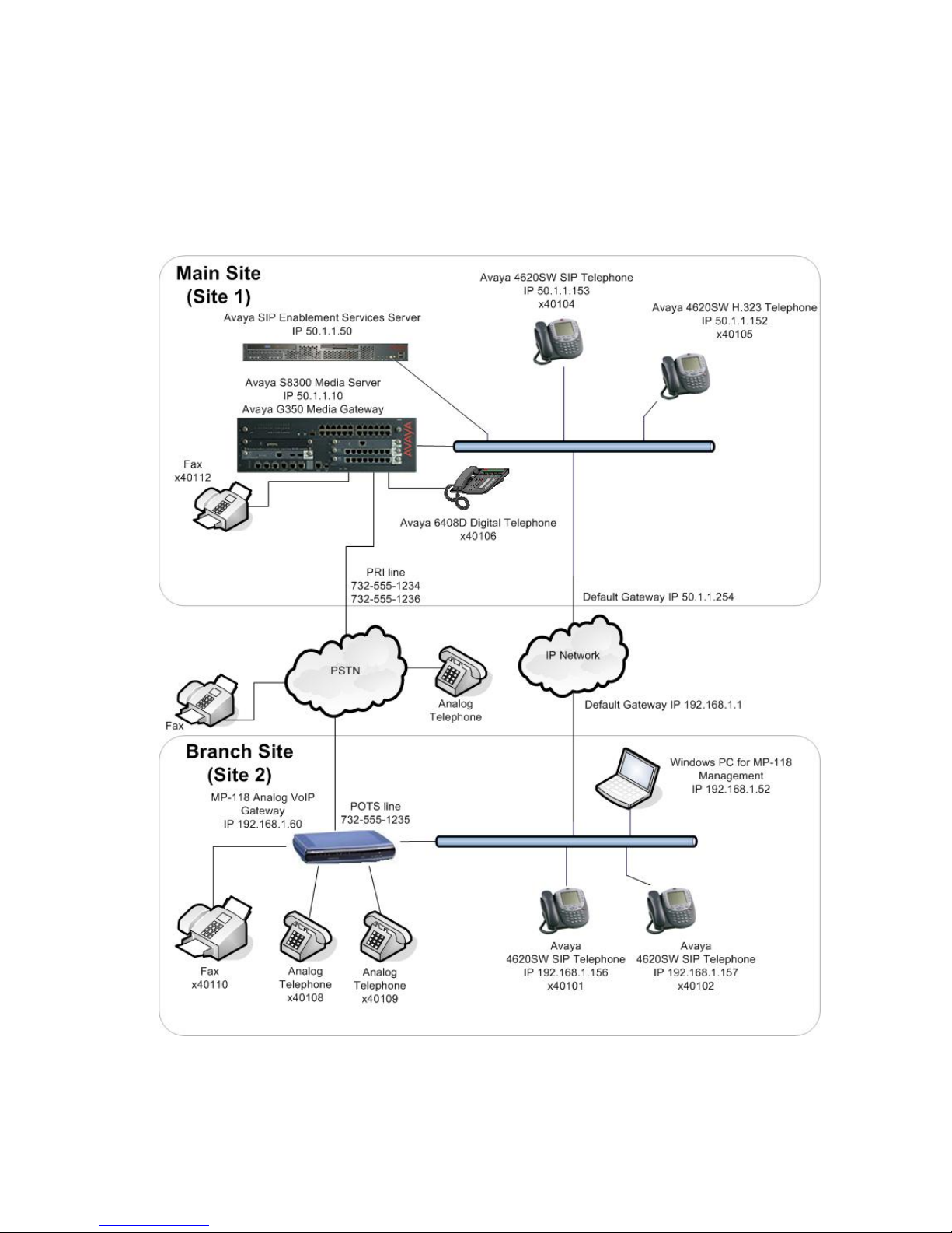
Figure 1 illustrates the configuration used in these Application Notes. In the sample configuration,
two sites are connected via an IP network. The main site has an Avaya SES and an Avaya S8300
Media Server running Avaya Communication Manager in an Avaya G350 Media Gateway.
Endpoints include an Avaya 4600 Series IP Telephone (with SIP firmware), an Avaya 4600 Series
IP Telephone (with H.323 firmware), an Avaya 6408D Digital Telephone, and a fax machine. An
ISDN-PRI trunk connects the media gateway to the PSTN.
The branch site has an AudioCodes MP-118 Analog VoIP Gateway with two analog telephones, and
a fax machine. The branch site also has two Avaya 4600 Series IP Telephones (with SIP firmware).
The MP-118 connects the branch site to the PSTN via an FXO (POTS) trunk which is only used if
the data WAN is unavailable. The other three FXO ports were not connected. Normally, all
outbound calls from the branch location pass across the data WAN, through the Main site and reach
the PSTN via an ISDN-PRI trunk at the Main site. Conversely, all inbound calls for the branch site
come from the PSTN across a trunk connected to the Main site then passed over the data WAN to
the branch.
All SIP telephones and analog telephones at both sites are registered directly to Avaya SES and are
administered as Outboard Proxy SIP (OPS) stations in Avaya Communication Manager. The SIP
telephones at the branch site use the IP network gateway as the default gateway. The MP-118 only
supports the operation of the analog endpoints and is not required for the SIP telephones. As a result,
CTM; Reviewed:
SPOC 11/29/2007
Solution & Interoperability Test Lab Application Notes
©2006 Avaya Inc. All Rights Reserved.
2 of 51
AudioCodesMP118.doc
Page 3
if the data WAN is unavailable, the MP-118 allows the analog telephones to keep functioning but the
SIP telephones will not.
One of the DID numbers of the ISDN-PRI trunk to the Main Site is mapped to a telephone extension
at the Main Site. The other is mapped to a telephone extension at the Branch Site. The DID number
of the POTS line is mapped to an extension at the Branch Site which could be used if the data WAN
is unavailable.
CTM; Reviewed:
SPOC 11/29/2007
Solution & Interoperability Test Lab Application Notes
Figure 1: MP-118 Test Configuration
©2006 Avaya Inc. All Rights Reserved.
3 of 51
AudioCodesMP118.doc
Page 4

2. Equipment and Software Validated
The following equipment and software/firmware were used for the sample configuration provided:
Equipment Software/Firmware
Avaya S8300 Media Server with Avaya G350
Media Gateway
Avaya Communication Manager 3.1.2
(R013x.01.2.635.0)
This is a post-GA build needed to
support T.38 fax with the MP-118.
Avaya SIP Enablement Services (SES) 3.1 (build 18)
Avaya 4620SW IP Telephones SIP version 2.2.2
H.323 version 2.3
Avaya 6408D Digital Telephone Analog Telephones Analog Fax Machines Windows PCs Windows XP Professional
AudioCodes MP-118 Analog VoIP Gateway 5.00A.011.008
3. Configure Avaya Communication Manager
The communication between Avaya Communication Manager and Avaya SES is via a SIP trunk
group. All SIP signaling for calls between Avaya Communication Manager and the MP-118 passes
through Avaya SES via this trunk group. This section describes the steps for configuring this trunk
group and associated signaling group. In addition, this section describes the configuration of stations
as OPS stations, which is required for each analog telephone, and fax machine connected to the MP-
118.
The following configuration of Avaya Communication Manager was performed using the System
Access Terminal (SAT). After the completion of the configuration in this section, perform a save
translation command to make the changes permanent.
CTM; Reviewed:
SPOC 11/29/2007
Solution & Interoperability Test Lab Application Notes
©2006 Avaya Inc. All Rights Reserved.
4 of 51
AudioCodesMP118.doc
Page 5

Step Description
1. Use the display system-parameters customer-options command to verify that
sufficient SIP trunk capacity exists. On Page 2, verify that the number of SIP trunks
supported by the system is sufficient for the number of SIP trunks needed. Each SIP
call between two SIP endpoints (whether internal or external) requires two SIP trunks
for the duration of the call. Thus, a call from a SIP telephone to another SIP telephone
will use two SIP trunks. A call between a non-SIP telephone and a SIP telephone will
only use one trunk. In this solution, each analog endpoint at the branch counts as a SIP
telephone.
The license file installed on the system controls the maximum permitted. If a required
feature is not enabled or there is insufficient capacity, contact an authorized Avaya
sales representative to make the appropriate changes.
display system-parameters customer-options Page 2 of 10
OPTIONAL FEATURES
IP PORT CAPACITIES USED
Maximum Administered H.323 Trunks: 100 10
Maximum Concurrently Registered IP Stations: 20 0
Maximum Administered Remote Office Trunks: 0 0
Maximum Concurrently Registered Remote Office Stations: 0 0
Maximum Concurrently Registered IP eCons: 0 0
Max Concur Registered Unauthenticated H.323 Stations: 0 0
Maximum Video Capable H.323 Stations: 0 0
Maximum Video Capable IP Softphones: 0 0
Maximum Administered SIP Trunks: 100 24
Maximum Number of DS1 Boards with Echo Cancellation: 0 0
Maximum TN2501 VAL Boards: 0 0
Maximum G250/G350/G700 VAL Sources: 5 1
Maximum TN2602 Boards with 80 VoIP Channels: 0 0
Maximum TN2602 Boards with 320 VoIP Channels: 0 0
Maximum Number of Expanded Meet-me Conference Ports: 10 0
(NOTE: You must logoff & login to effect the permission changes.)
2. Use the change node-name ip command to assign the node name and IP address for
Avaya SES at the enterprise site. In this case, SES and 50.1.1.50 are being used,
respectively. The node name SES will be used throughout the other configuration
forms of Avaya Communication Manager. In this example, procr and 50.1.1.10 are the
name and IP address assigned to the Avaya S8300 Media Server.
change node-names ip Page 1 of 1
IP NODE NAMES
Name IP Address Name IP Address
SES 50 .1 .1 .50 . . .
default 0 .0 .0 .0 . . .
procr 50 .1 .1 .10 . . .
CTM; Reviewed:
SPOC 11/29/2007
Solution & Interoperability Test Lab Application Notes
©2006 Avaya Inc. All Rights Reserved.
5 of 51
AudioCodesMP118.doc
Page 6

Step Description
3. Use the change ip-network-region n command, where n is the number of the region
to be changed, to define the connectivity settings for all VoIP resources and IP
endpoints within the region. Select an IP network region that will contain the Avaya
SES server. The association between this IP network region and the Avaya SES server
will be done on the Signaling Group form as shown in Step 6. In the case of the
compliance test, the same IP network region that contains the Avaya S8300 Media
Server and Avaya IP Telephones was selected to contain the Avaya SES server. By
default, the Media Server and IP telephones are in IP Network Region 1.
On the IP Network Region form:
The Authoritative Domain field is configured to match the domain name
configured on Avaya SES. In this configuration, the domain name is
devcon.com. This name will appear in the “From” header of SIP messages
originating from this IP region.
By default, IP-IP Direct Audio (shuffling) is enabled to allow audio traffic to
be sent directly between IP endpoints without using media resources in the
Avaya G350 Media Gateway. This is true for both intra-region and inter-region
IP-IP Direct Audio. Shuffling can be further restricted at the trunk level on the
Signaling Group form.
The Codec Set is set to the number of the IP codec set to be used for calls
within this IP network region. If different IP network regions are used for the
Avaya S8300 Media Server and the Avaya SES server, then Page 3 of each IP
Network Region form must be used to specify the codec set for inter-region
communications.
The Audio PHB Value is 46, which translates to a DiffServ header value of
0xb8.
The default values can be used for all other fields.
change ip-network-region 1 Page 1 of 19
IP NETWORK REGION
Region: 1
Location: 1 Authoritative Domain: devcon.com
Name:
MEDIA PARAMETERS Intra-region IP-IP Direct Audio: yes
Codec Set: 1 Inter-region IP-IP Direct Audio: yes
UDP Port Min: 2048 IP Audio Hairpinning? y
UDP Port Max: 3027
DIFFSERV/TOS PARAMETERS RTCP Reporting Enabled? y
Call Control PHB Value: 34 RTCP MONITOR SERVER PARAMETERS
Audio PHB Value: 46 Use Default Server Parameters? y
Video PHB Value: 26
802.1P/Q PARAMETERS
Call Control 802.1p Priority: 6
Audio 802.1p Priority: 6
Video 802.1p Priority: 5 AUDIO RESOURCE RESERVATION PARAMETERS
H.323 IP ENDPOINTS RSVP Enabled? n
H.323 Link Bounce Recovery? y
Idle Traffic Interval (sec): 20
Keep-Alive Interval (sec): 5
Keep-Alive Count: 5
CTM; Reviewed:
SPOC 11/29/2007
Solution & Interoperability Test Lab Application Notes
©2006 Avaya Inc. All Rights Reserved.
6 of 51
AudioCodesMP118.doc
Page 7

Step Description
4. Use the change ip-codec-set n command, where n is the codec set value specified in
Step 3, to enter the supported audio codecs for calls routed to Avaya SES. Multiple
codecs can be listed in priority order to allow the codec to be negotiated during call
establishment. The list should include the codecs the enterprise wishes to support
within the normal trade-off of bandwidth versus voice quality. The example below
shows the values used in the compliance test.
change ip-codec-set 1 Page 1 of 2
IP Codec Set
Codec Set: 1
Audio Silence Frames Packet
Codec Suppression Per Pkt Size(ms)
1: G.711MU n 2 20
2: G.729AB n 2 20
3:
5. On Page 2, the FAX Mode field must be set to t.38-standard to support the fax
machines. The Modem field should be set to off. The screen below shows the setting
used for the fax testing.
change ip-codec-set 1 Page 2 of 2
IP Codec Set
Allow Direct-IP Multimedia? n
Mode Redundancy
FAX t.38-standard 0
Modem off 0
TDD/TTY US 3
Clear-channel n 0
CTM; Reviewed:
SPOC 11/29/2007
Solution & Interoperability Test Lab Application Notes
©2006 Avaya Inc. All Rights Reserved.
7 of 51
AudioCodesMP118.doc
Page 8

Step Description
6. Use the add signaling group n command, where n is the number of an unused
signaling group, to create the SIP signaling group as follows:
Set the Group Type field to sip.
The Transport Method field will default to tls (Transport Layer Security).
TLS is the only link protocol that is supported for communication between
Avaya SES and Avaya Communication Manager.
Specify the Avaya S8300 Media Server (node name procr) and the Avaya SES
Server (node name SES) as the two ends of the signaling group in the Near-
end Node Name and the Far-end Node Name fields, respectively. These field
values are taken from the IP Node Names form shown in Step 2. For
alternative configurations that use a C-LAN board, the near (local) end of the
SIP signaling group will be the C-LAN board instead of the Media Server.
Ensure that the recommended TLS port value of 5061 is configured in the
Near-end Listen Port and the Far-end Listen Port fields.
In the Far-end Network Region field, enter the IP network region value
assigned in the IP Network Region form in Step 3. This defines which IP
network region contains the Avaya SES server. If the Far-end Network
Region field is different from the near-end network region, the preferred codec
will be selected from the IP codec set assigned for the inter-region connectivity
for the pair of network regions.
Enter the domain name of Avaya SES in the Far-end Domain field. In this
configuration, the domain name is devcon.com. This domain is specified in the
Uniform Resource Identifier (URI) of the SIP “To” header in the INVITE
message.
The Direct IP-IP Audio Connections field is set to y.
The DTMF over IP field must be set to the default value of rtp-payload for a
SIP trunk. This value enables Avaya Communication Manager to send DTMF
transmissions using RFC 2833.
The default values for the other fields may be used.
add signaling-group 1 Page 1 of 1
SIGNALING GROUP
Group Number: 1 Group Type: sip
Transport Method: tls
Near-end Node Name: procr Far-end Node Name: SES
Near-end Listen Port: 5061 Far-end Listen Port: 5061
Far-end Network Region: 1
Far-end Domain: devcon.com
Bypass If IP Threshold Exceeded? n
DTMF over IP: rtp-payload Direct IP-IP Audio Connections? y
IP Audio Hairpinning? n
Session Establishment Timer(min): 120
CTM; Reviewed:
SPOC 11/29/2007
Solution & Interoperability Test Lab Application Notes
©2006 Avaya Inc. All Rights Reserved.
8 of 51
AudioCodesMP118.doc
Page 9

Step Description
7. Add a SIP trunk group by using the add trunk-group n command, where n is the
number of an unused trunk group. For the compliance test, trunk group number 1 was
chosen.
On Page 1, set the fields to the following values:
Set the Group Type field to sip.
Choose a descriptive Group Name.
Specify an available trunk access code (TAC) that is consistent with the
existing dial plan.
Set the Service Type field to tie.
Specify the signaling group associated with this trunk group in the Signaling
Group field as previously specified in Step 6.
Specify the Number of Members supported by this SIP trunk group. As
mentioned earlier, each SIP call between two SIP endpoints (whether internal
or external) requires two SIP trunks for the duration of the call. Thus, a call
from a SIP telephone to another SIP telephone will use two SIP trunks. A call
between a non-SIP telephone and a SIP telephone will only use one trunk. In
this solution, each analog endpoint at the branch counts as a SIP telephone.
The default values may be retained for the other fields.
add trunk-group 1 Page 1 of 21
TRUNK GROUP
Group Number: 1 Group Type: sip CDR Reports: y
Group Name: To SES 50.1.1.50 COR: 1 TN: 1 TAC: 101
Direction: two-way Outgoing Display? n
Dial Access? n Night Service:
Queue Length: 0
Service Type: tie Auth Code? n
Signaling Group: 1
Number of Members: 24
8. On Page 3:
add trunk-group 1 Page 3 of 21
TRUNK FEATURES
ACA Assignment? n Measured: none
Maintenance Tests? y
Numbering Format: public
Prepend '+' to Calling Number? n
Replace Unavailable Numbers? n
CTM; Reviewed:
SPOC 11/29/2007
Verify the Numbering Format field is set to public. This field specifies the
format of the calling party number sent to the far-end.
The default values may be retained for the other fields.
Solution & Interoperability Test Lab Application Notes
©2006 Avaya Inc. All Rights Reserved.
AudioCodesMP118.doc
9 of 51
Page 10

Step Description
9. Use the change public-unknown-numbering 0 command to define the full calling
party number to be sent to the far-end. Add an entry for the trunk group defined in
Step 7. In the example shown below, all calls originating from a 5-digit extension
beginning with 4 and routed across trunk group 1 will be sent as a 5 digit calling
number. This calling party number will be sent to the far-end in the SIP “From”
header.
change public-unknown-numbering 0 Page 1 of 2
NUMBERING - PUBLIC/UNKNOWN FORMAT
Total Total
Ext Ext Trk CPN CPN Ext Ext Trk CPN CPN
Len Code Grp(s) Prefix Len Len Code Grp(s) Prefix Len
5 4 1 5
10. Create a route pattern that will use the SIP trunk that connects to Avaya SES. In
general, a route pattern is not required for calling between SIP endpoints registered to
the Avaya SES. This includes the dialing scenarios performed in the compliance test.
However, some transfer scenarios using alpha-numeric handles (i.e., user names)
instead of extensions require a default route pattern. The creation of this default route
pattern is included here for completeness.
To create a route pattern, use the change route-pattern n command, where n is the
number of an unused route pattern. Enter a descriptive name for the Pattern Name
field. Set the Grp No field to the trunk group number created for the SIP trunk. Set
the Facility Restriction Level (FRL) field to a level that allows access to this trunk for
all users that require it. The value of 0 is the least restrictive level. The default values
may be retained for all other fields.
change route-pattern 1 Page 1 of 3
Pattern Number: 3 Pattern Name: SIP
SCCAN? n Secure SIP? n
Grp FRL NPA Pfx Hop Toll No. Inserted DCS/ IXC
No Mrk Lmt List Del Digits QSIG
Dgts Intw
1: 1 0 n user
2: n user
3: n user
4: n user
5: n user
6: n user
BCC VALUE TSC CA-TSC ITC BCIE Service/Feature PARM No. Numbering LAR
0 1 2 3 4 W Request Dgts Format
Subaddress
1: y y y y y n n rest none
2: y y y y y n n rest none
3: y y y y y n n rest none
4: y y y y y n n rest none
5: y y y y y n n rest none
6: y y y y y n n rest none
CTM; Reviewed:
SPOC 11/29/2007
Solution & Interoperability Test Lab Application Notes
©2006 Avaya Inc. All Rights Reserved.
10 of 51
AudioCodesMP118.doc
Page 11

Step Description
11. Use the change locations command to assign the default SIP route pattern to the
location. In the compliance test, all SIP endpoints whether at the main or branch site
are part of a single location defined in Avaya Communication Manager. This location
uses the default name of Main and is shown in the example below. Enter the route
pattern number from the previous step in the Proxy Sel. Rte. Pat. field. The default
values may be retained for all other fields.
change locations Page 1 of 4
LOCATIONS
ARS Prefix 1 Required For 10-Digit NANP Calls? y
Loc. Name Timezone Rule NPA ARS Attd Pre- Proxy Sel.
No. Offset FAC FAC fix Rte. Pat.
1: Main + 00:00 0 1
2:
3:
12. All SIP stations are configured as OPS stations on Avaya Communication Manager.
This includes the analog telephones, and fax machine connected to the MP-118, which
appear as SIP stations to Avaya Communication Manager.
Use the display system-parameters customer-options command to verify Avaya
Communication Manager has sufficient OPS capacity available to add the OPS stations
needed for the SIP and analog endpoints at the branch office in Figure 1. If there is
insufficient capacity, contact an authorized Avaya sales representative or business
partner to make the appropriate changes.
display system-parameters customer-options Page 1 of 10
OPTIONAL FEATURES
G3 Version: V13
Location: 1 RFA System ID (SID): 1
Platform: 13 RFA Module ID (MID): 1
USED
Platform Maximum Ports: 900 121
Maximum Stations: 450 41
Maximum XMOBILE Stations: 0 0
Maximum Off-PBX Telephones - EC500: 50 0
Maximum Off-PBX Telephones - OPS: 50 23
Maximum Off-PBX Telephones - SCCAN: 0 0
CTM; Reviewed:
SPOC 11/29/2007
Solution & Interoperability Test Lab Application Notes
©2006 Avaya Inc. All Rights Reserved.
11 of 51
AudioCodesMP118.doc
Page 12

Step Description
13. To add a station, use the add station n command where n is an unused extension
number. Use the default value of 6408D+ for the Type field. Enter an X in the Port
field. This indicates a station is being added without identifying a physical port for the
station to use. Enter a descriptive name in the Name field. The default values may be
retained for all other fields.
add station 40108 Page 1 of 4
STATION
Extension: 40108 Lock Messages? n BCC: 0
Type: 6408D+ Security Code: TN: 1
Port: X Coverage Path 1: 1 COR: 1
Name: Branch 1 Coverage Path 2: COS: 1
Hunt-to Station:
STATION OPTIONS
Loss Group: 2 Personalized Ringing Pattern: 1
Data Module? n Message Lamp Ext: 40108
Speakerphone: 2-way Mute Button Enabled? y
Display Language: english
Media Complex Ext:
IP SoftPhone? n
14. On Page 2, set Restrict Last Appearance to n. This will allow the last call
appearance to be used for either an incoming or outgoing call.
add station 40108 Page 2 of 5
STATION
FEATURE OPTIONS
LWC Reception: audix Auto Select Any Idle Appearance? n
LWC Activation? y Coverage Msg Retrieval? y
LWC Log External Calls? n Auto Answer: none
CDR Privacy? n Data Restriction? n
Redirect Notification? y Idle Appearance Preference? n
Per Button Ring Control? n Bridged Idle Line Preference? n
Bridged Call Alerting? y Restrict Last Appearance? n
Active Station Ringing: single
H.320 Conversion? n Per Station CPN - Send Calling Number?
Service Link Mode: as-needed
Multimedia Mode: basic Audible Message Waiting? n
MWI Served User Type: Display Client Redirection? n
AUDIX Name: IA770 Select Last Used Appearance? n
Coverage After Forwarding? s
Direct IP-IP Audio Connections? y
Emergency Location Ext: 40108 IP Audio Hairpinning? n
CTM; Reviewed:
SPOC 11/29/2007
Solution & Interoperability Test Lab Application Notes
©2006 Avaya Inc. All Rights Reserved.
12 of 51
AudioCodesMP118.doc
Page 13

Step Description
15. On Page 3, under BUTTON ASSIGNMENTS, create the appropriate number of call
appearances for the SIP endpoint being configured. In general, the appropriate number
of call appearances on Avaya Communication Manager is the same as the number of
call appearances supported by the endpoint. To create a call appearance, enter call-
appr as the button assignment. The example below shows the configuration of one of
the analog endpoints connected to the MP-118. The analog endpoints used in the
compliance test were all configured with two call appearances.
There are two Feature Name Extensions (FNEs) that require the assignment of feature
buttons in order to operate. The Automatic Callback FNE requires the assignment of an
auto-cback button. The Conference On Answer FNE requires the assignment of a nohld-cnf button. Both of these button assignments are shown in the example below.
add station 40108 Page 3 of 4
STATION
SITE DATA
Room: Headset? n
Jack: Speaker? n
Cable: Mounting: d
Floor: Cord Length: 0
Building: Set Color:
ABBREVIATED DIALING
List1: List2: List3:
BUTTON ASSIGNMENTS
1: call-appr 5: auto-cback
2: call-appr 6: no-hld-cnf
3: 7:
4: 8:
16. Map the Avaya Communication Manager extension to the Avaya SES media server
extension defined in Section 4, Step 8 with the add off-pbx-telephone station-
mapping command. Enter the values as shown below:
Station Extension: Avaya Communication Manager extension
Application: OPS
Phone Number: Avaya SES media server extension
Trunk Selection: The SIP trunk group number
Configuration Set: Enter a valid configuration set. The compliance test used
configuration set 1 which contained the default values.
add off-pbx-telephone station-mapping Page 1 of 2
STATIONS WITH OFF-PBX TELEPHONE INTEGRATION
Station Application Dial Phone Number Trunk Configuration
Extension Prefix Selection Set
40108 OPS - 40108 1 1
-
CTM; Reviewed:
SPOC 11/29/2007
Solution & Interoperability Test Lab Application Notes
©2006 Avaya Inc. All Rights Reserved.
13 of 51
AudioCodesMP118.doc
Page 14
Step Description
17. On Page 2, set the Call Limit to the number of call appearances set on the station form
in Step 15. Verify that the Mapping Mode is set to both. This setting allows the OPS
station to both originate and terminate calls.
add off-pbx-telephone station-mapping Page 2 of 2
STATIONS WITH OFF-PBX TELEPHONE INTEGRATION
Station Call Mapping Calls Bridged
Extension Limit Mode Allowed Calls
40108 2 both all both
18. Repeat Steps 13 -17 for each remaining endpoint located at the branch office. The
branch office has five user endpoints: two analog telephones connected to the MP-118
(x40108 and x40109), two Avaya 4600 Series SIP Telephones (x40101 and x40102),
and a fax machine (x40110). In this configuration, the MP-118 gateway itself must
also be registered as a separate endpoint. For the compliance test, extension 44444 was
created for this purpose with the same characteristics as the Avaya SIP telephones at
this site.
19. To map a DID number to a station at the main or branch office, use the change inc-
call-handling-trmt trunk-group n command, where n is the trunk group number
connected to the PSTN from the Avaya G350 Media Gateway. The compliance test
used trunk group 2 to connect to the PSTN. This trunk group configuration is not
shown in these Application Notes. The example below shows two incoming 11-digit
numbers being deleted and replaced with the extension number of the desired station.
change inc-call-handling-trmt trunk-group 2 Page 1 of 3
INCOMING CALL HANDLING TREATMENT
Service/ Called Called Del Insert
Feature Len Number
tie 11 17325551234 11 40104
tie 11 17325551236 11 40108
CTM; Reviewed:
SPOC 11/29/2007
Solution & Interoperability Test Lab Application Notes
©2006 Avaya Inc. All Rights Reserved.
14 of 51
AudioCodesMP118.doc
Page 15
4. Configure Avaya SES
This section covers the configuration of Avaya SES. Avaya SES is configured via an Internet
browser using the administration web interface. It is assumed that Avaya SES software and the
license file have already been installed on the server. During the software installation, the
installation script is run from the Linux shell of the server to specify the IP network properties of the
server along with other parameters. For additional information on these installation tasks, refer to
[5].
Step Description
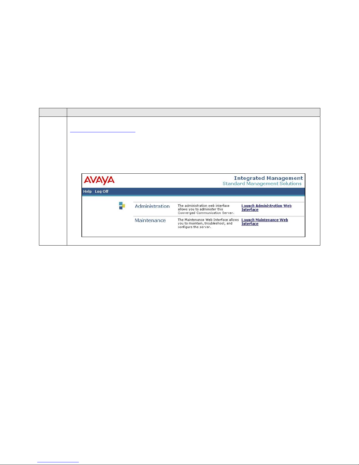
1. Access the Avaya SES administration web interface by entering
http://<ip-addr>/admin
address of the Avaya SES server.
Log in with the appropriate credentials and then select the Launch Administration
Web Interface link from the main page as shown below.
as the URL in an Internet browser, where <ip-addr> is the IP
CTM; Reviewed:
SPOC 11/29/2007
Solution & Interoperability Test Lab Application Notes
©2006 Avaya Inc. All Rights Reserved.
15 of 51
AudioCodesMP118.doc
Page 16
Step Description
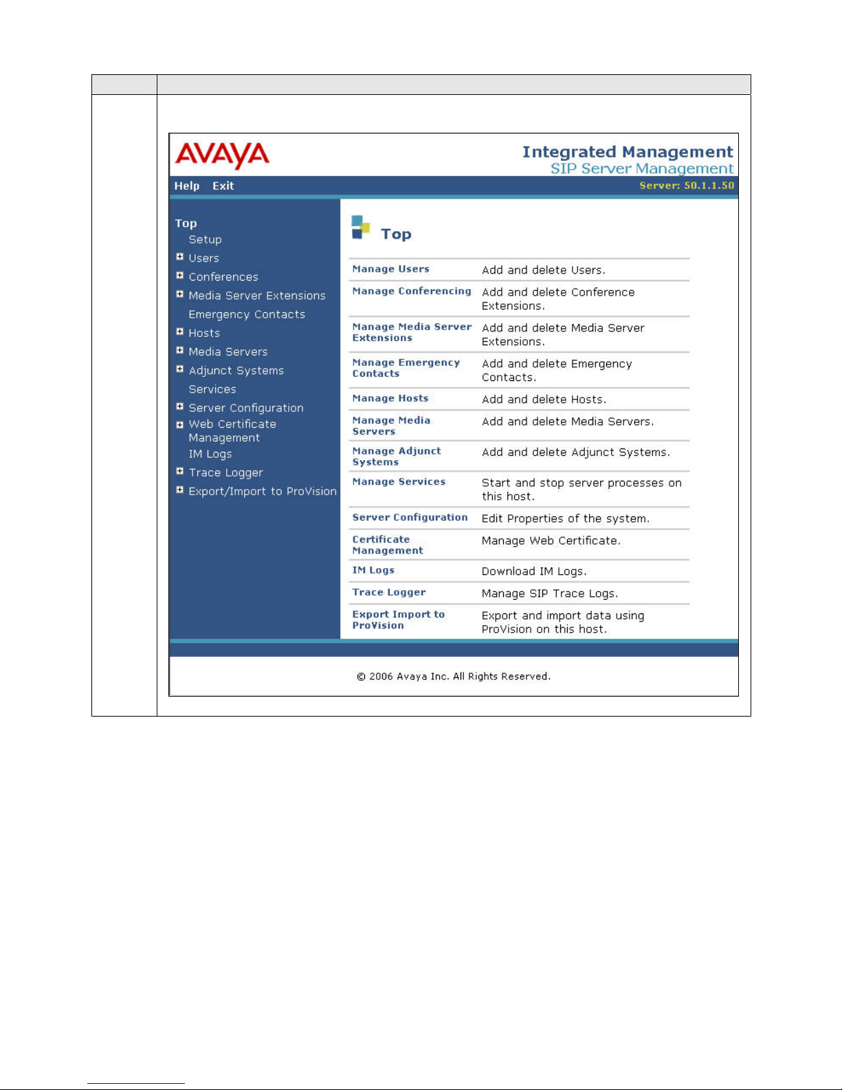
2. The Avaya SES Administration Home Page will be displayed as shown below.
CTM; Reviewed:
SPOC 11/29/2007
Solution & Interoperability Test Lab Application Notes
©2006 Avaya Inc. All Rights Reserved.
16 of 51
AudioCodesMP118.doc
Page 17
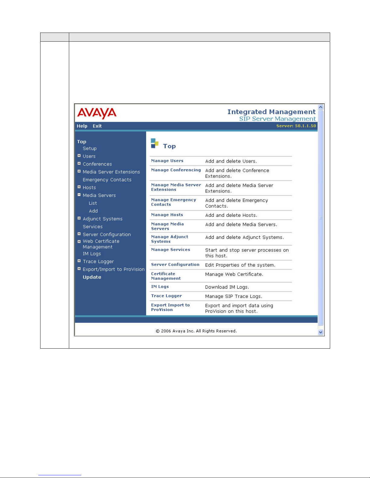
Step Description
3. After making changes within Avaya SES, it is necessary to commit the database
changes using the Update link that appears when changes are pending. Perform this
step by clicking on the Update link found in the bottom of the blue navigation bar on
the left side of any of the Avaya SES administration pages as shown below. It is
recommended that this be done after making each set of changes described in the
following steps.
CTM; Reviewed:
SPOC 11/29/2007
Solution & Interoperability Test Lab Application Notes
©2006 Avaya Inc. All Rights Reserved.
17 of 51
AudioCodesMP118.doc
Page 18
Step Description
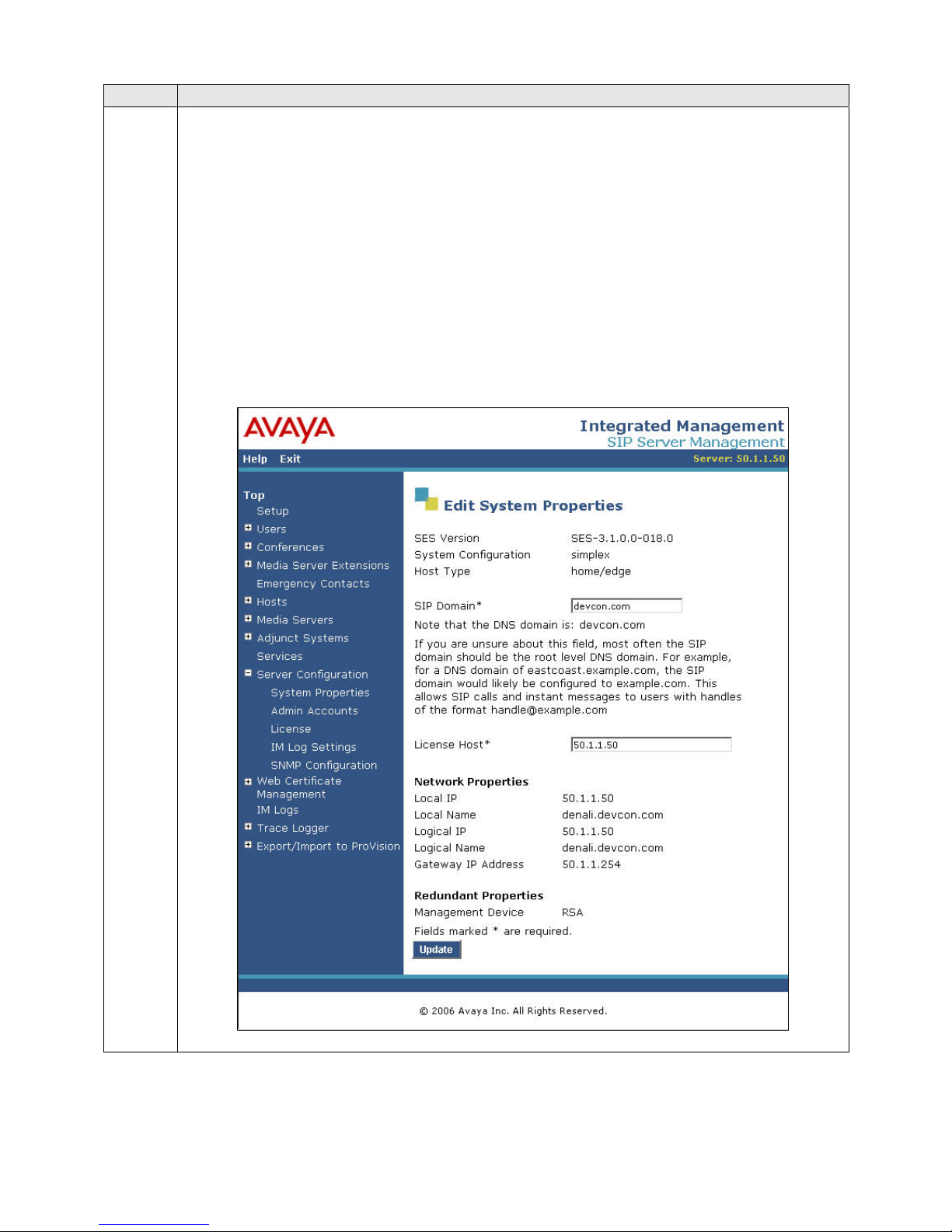
4. From the left pane of the administration web interface, expand the Server
Configuration option and select System Properties. The Edit System Properties
page displays the software version in the SES Version field and the network properties
entered during the installation process.
On the Edit System Properties page:
Enter the SIP Domain name assigned to Avaya SES. This must match the
Authoritative Domain field configured on Avaya Communication Manager
shown in Section 3, Step 3.
Enter the License Host field. This is the host name, the fully qualified domain
name, or the IP address of the SIP proxy server that is running the WebLM
application and has the associated license file installed.
After configuring the Edit System Properties page, click the Update button.
CTM; Reviewed:
SPOC 11/29/2007
Solution & Interoperability Test Lab Application Notes
©2006 Avaya Inc. All Rights Reserved.
18 of 51
AudioCodesMP118.doc
Page 19
Step Description
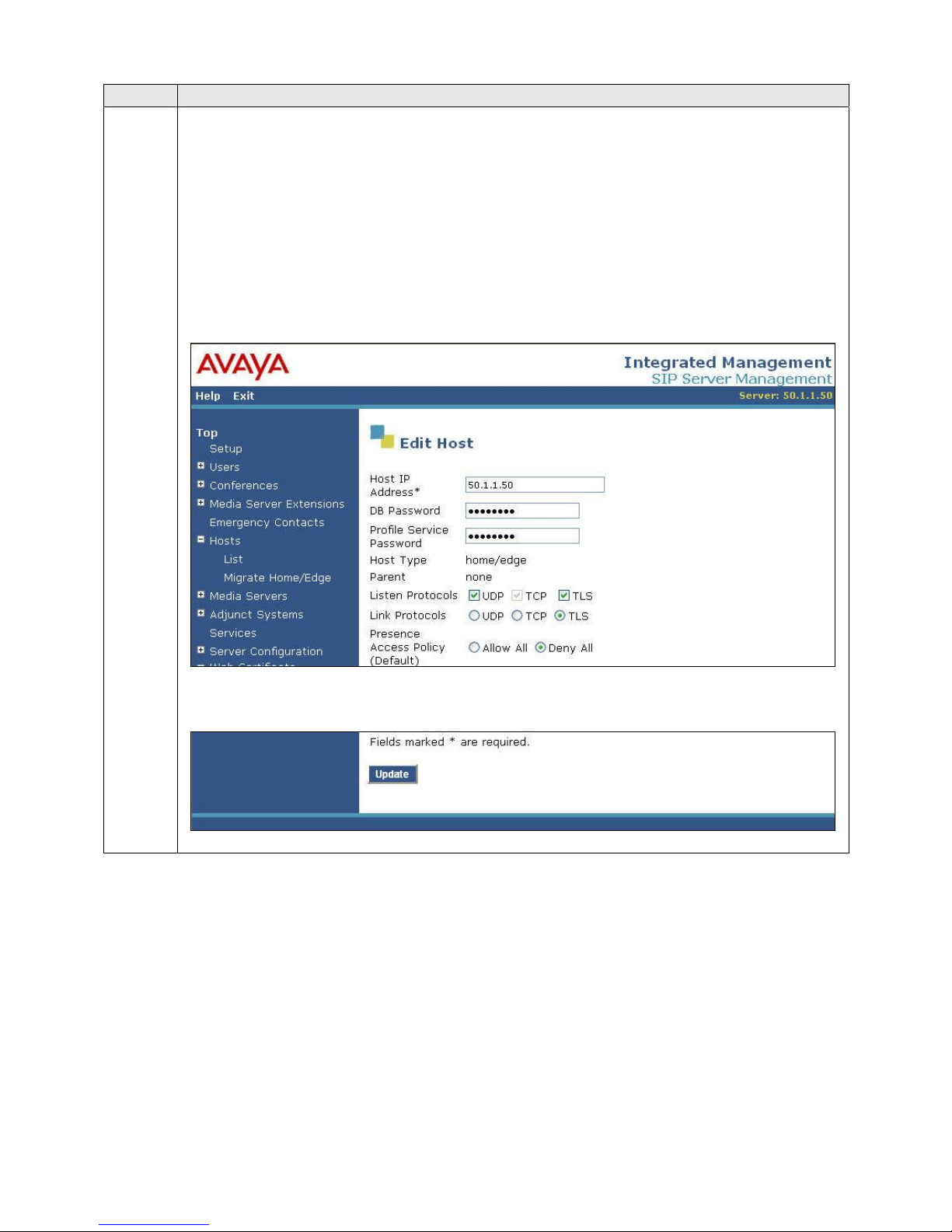
5. After setting up the domain on the Edit System Properties page, create a host
computer entry for Avaya SES. The following example shows the Edit Host page
since the host had already been added to the system.
The Edit Host page shown below is accessible by clicking on the Hosts Æ List link in
the left pane and then clicking on the Edit link under the Commands section of the
subsequent page that is displayed.
In the Host IP Address field, enter the IP address of the Avaya SES.
Enter the DB Password that was specified during the system installation.
The default values for the other fields may be used.
CTM; Reviewed:
SPOC 11/29/2007
Scroll down to the bottom of the page and click the Update button.
Solution & Interoperability Test Lab Application Notes
©2006 Avaya Inc. All Rights Reserved.
AudioCodesMP118.doc
19 of 51
Page 20
Step Description
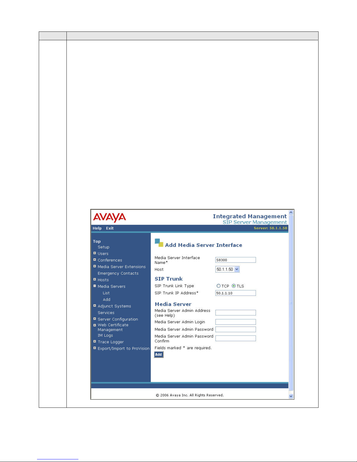
6. From the left pane of the administration web interface, expand the Media Servers
option and select Add to add the Avaya Media Server to the list of media servers
known to Avaya SES. Adding the media server will create the Avaya SES side of the
SIP trunk previously created in Avaya Communication Manager.
On the Add Media Server Interface page, enter the following information:
A descriptive name in the Media Server Interface Name field (e.g. S8300).
In the Host field, select the Avaya SES server from the pull-down menu that
will serve as the SIP proxy for this media server. Since there is only one Avaya
SES server in this configuration, the Host field is set to the host shown in Step
5.
Select TLS (Transport Link Security) for the SIP Trunk Link Type. TLS
provides encryption at the transport layer. TLS is the only link protocol that is
supported for communication between Avaya SES and Avaya Communication
Manager.
Enter the IP address of the Avaya S8300 Media Server in the SIP Trunk IP
Address field. In alternative configurations that use a C-LAN board, the SIP
Trunk IP Address would be the IP address of the C-LAN board.
The default values may be retained for all other fields.
After completing the Add Media Server Interface page, click the Add button.
CTM; Reviewed:
SPOC 11/29/2007
Solution & Interoperability Test Lab Application Notes
©2006 Avaya Inc. All Rights Reserved.
20 of 51
AudioCodesMP118.doc
Page 21
Step Description
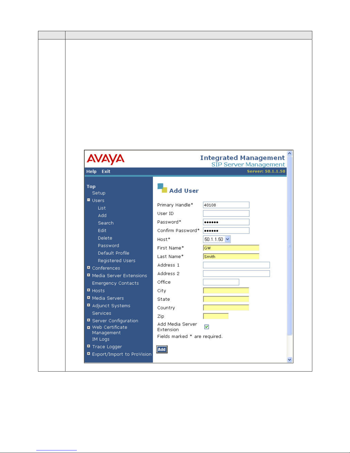
7. A user must be added on Avaya SES for each of the extensions at the branch office
created on Avaya Communication Manager in Section 3, Steps 13 – 17 including the
extension created for the MP-118 gateway itself. From the left pane, navigate to Users
Æ Add. Enter the values as shown below.
Primary Handle: Enter the extension for this user.
Password: Enter a valid password for logging into the SIP endpoint.
Confirm Password: Re-enter the password.
Host: Select the Avaya SES server from the pull-down menu.
First Name: Any descriptive name.
Last Name: Any descriptive name.
Check the Add Media Server Extension checkbox. Click the Add button to proceed.
A confirmation window will appear. Click Continue on this new page to proceed.
CTM; Reviewed:
SPOC 11/29/2007
Solution & Interoperability Test Lab Application Notes
©2006 Avaya Inc. All Rights Reserved.
21 of 51
AudioCodesMP118.doc
Page 22
Step Description
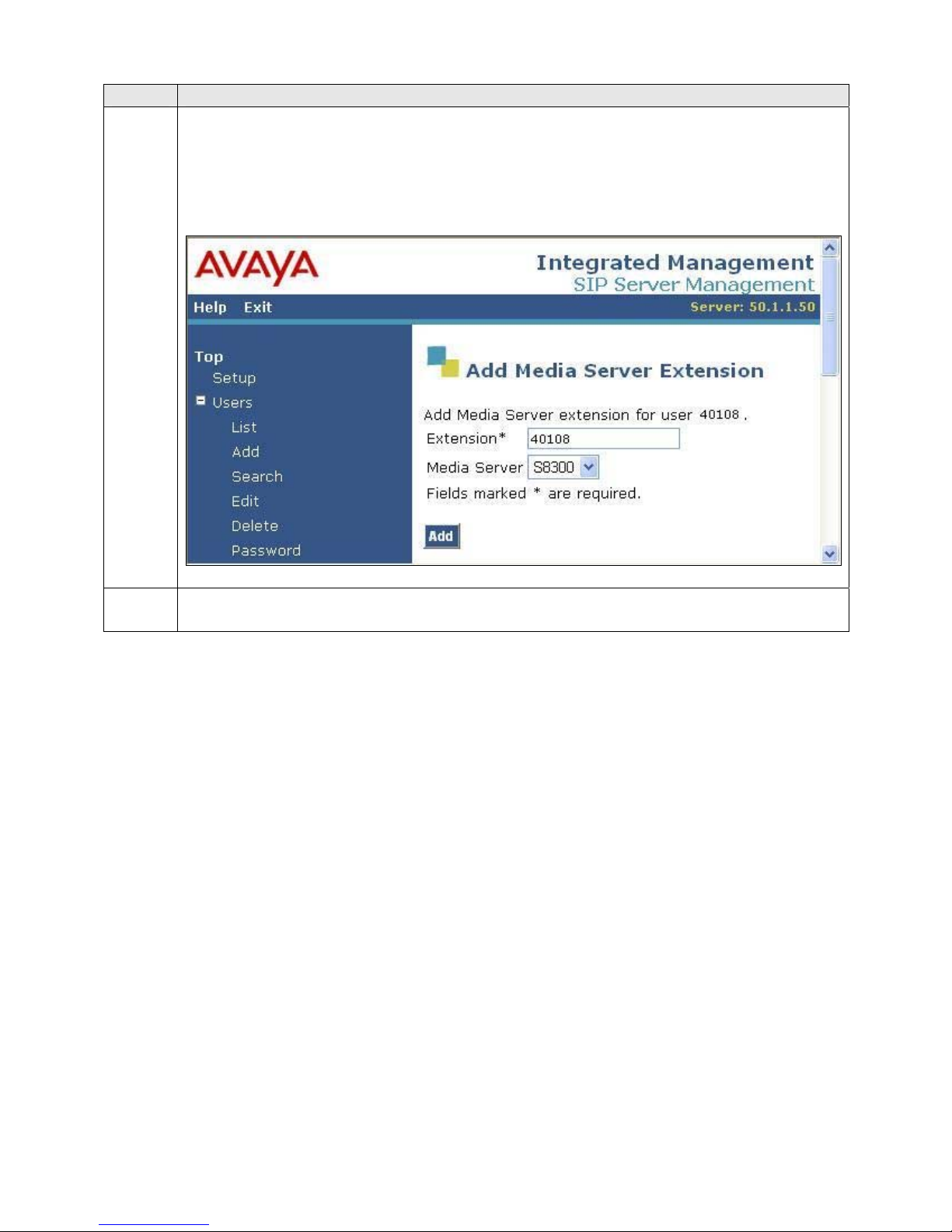
8. The Add Media Server Extension page will appear. In the Extension field, enter the
same extension used in the previous step. In the Media Server field, select from the
pull-down menu the name of the media server added in Step 6.
Click the Add button to complete the operation.
9. Repeat Steps 7 - 8 for each of the remaining stations at the branch office.
CTM; Reviewed:
SPOC 11/29/2007
Solution & Interoperability Test Lab Application Notes
©2006 Avaya Inc. All Rights Reserved.
22 of 51
AudioCodesMP118.doc
Page 23
5. Configure the MP-118
This section describes the procedures for configuring the MP-118. These procedures assume the
MP-118 has been installed using the procedures documented in [7] and has been assigned an IP
address.
Step Description
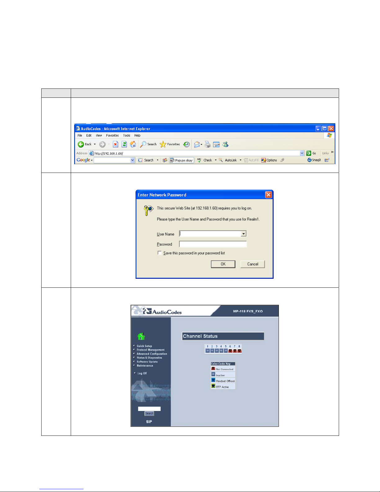
1. The configuration of the MP-118 is done via a Web browser. To access the device,
enter the IP address of the MP-118 in the Address field of the browser.
2. The following pop-up window will appear. Login with the proper credentials.
3. The MP-118 main page will appear as shown below.
CTM; Reviewed:
SPOC 11/29/2007
Solution & Interoperability Test Lab Application Notes
©2006 Avaya Inc. All Rights Reserved.
23 of 51
AudioCodesMP118.doc
Page 24
Step Description
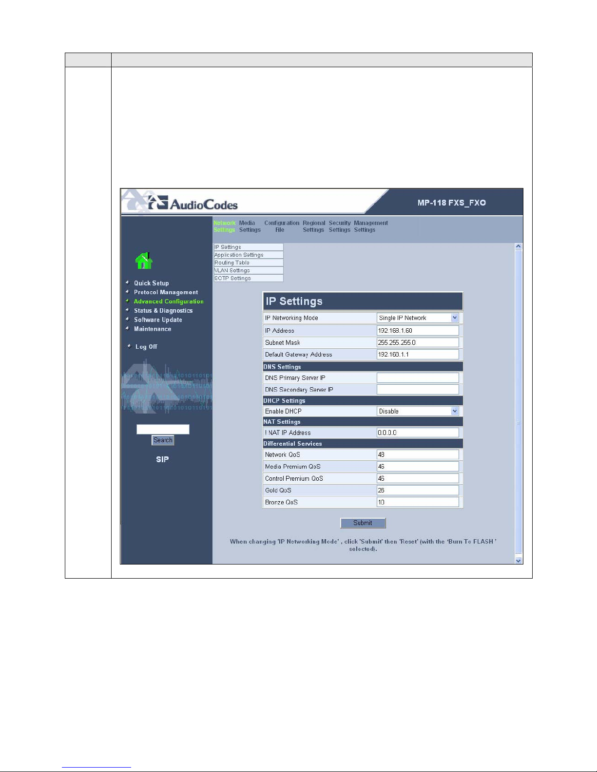
4. The network settings that were configured during installation can be viewed by
selecting Advanced Configuration in the left pane then navigating to Network
Settings Æ IP Settings in the right pane. If necessary, changes can be made to the
settings on this page followed by clicking Submit. For the compliance test, the IP
Address, Subnet Mask and Default Gateway Address were set to values consistent
with the test configuration shown in Figure 1. The Media Premium QoS must match
the Audio PHB Value set on Avaya Communication Manager in Section 3, Step 3.
Default values may be retained for all other values.
CTM; Reviewed:
SPOC 11/29/2007
Solution & Interoperability Test Lab Application Notes
©2006 Avaya Inc. All Rights Reserved.
24 of 51
AudioCodesMP118.doc
Page 25
Step Description
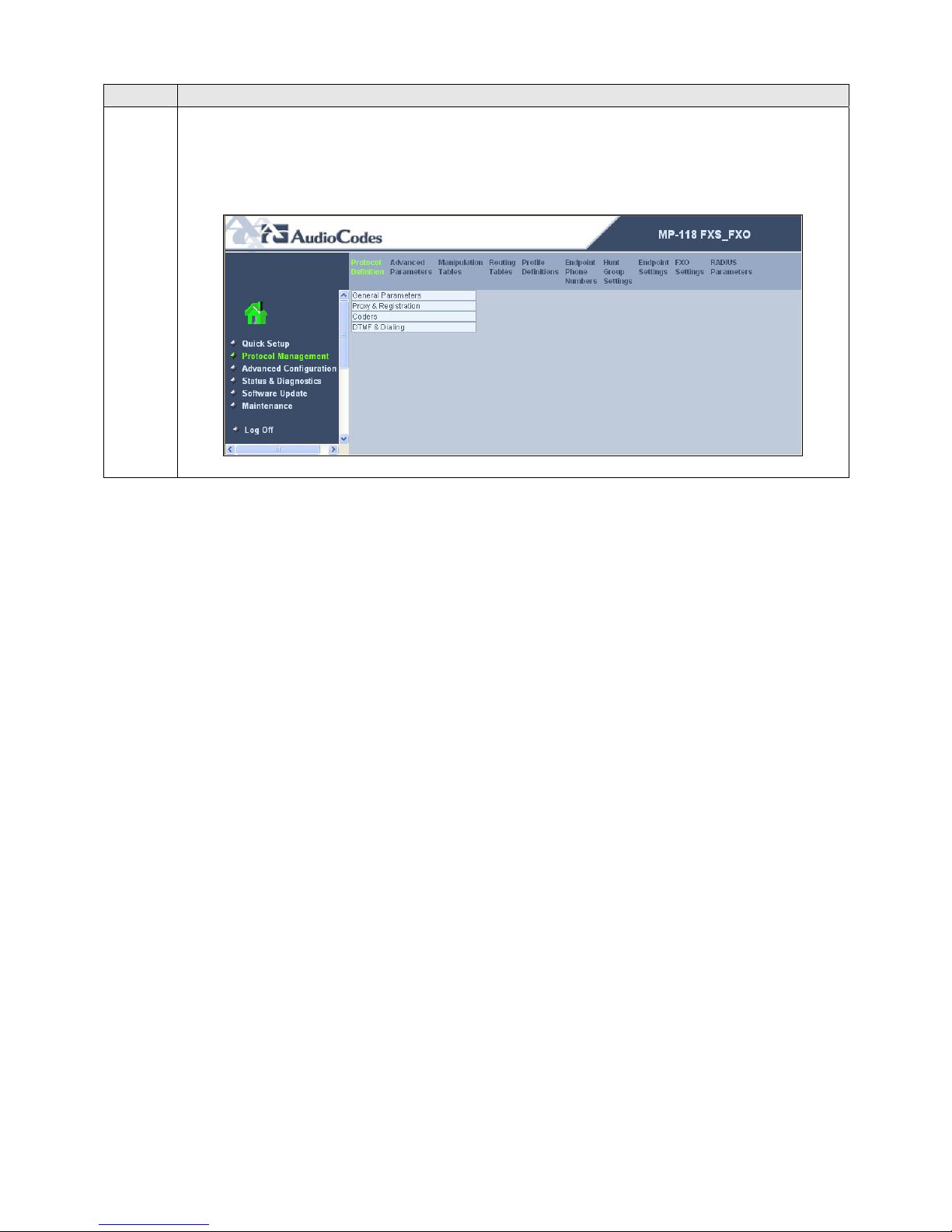
5.
Protocol Definition
To access these parameters, select Protocol Management in the left pane and navigate
to Protocol Definition in the right pane. The pull-down choices for Protocol
Definition are shown below.
CTM; Reviewed:
SPOC 11/29/2007
Solution & Interoperability Test Lab Application Notes
©2006 Avaya Inc. All Rights Reserved.
25 of 51
AudioCodesMP118.doc
Page 26
Step Description
6.
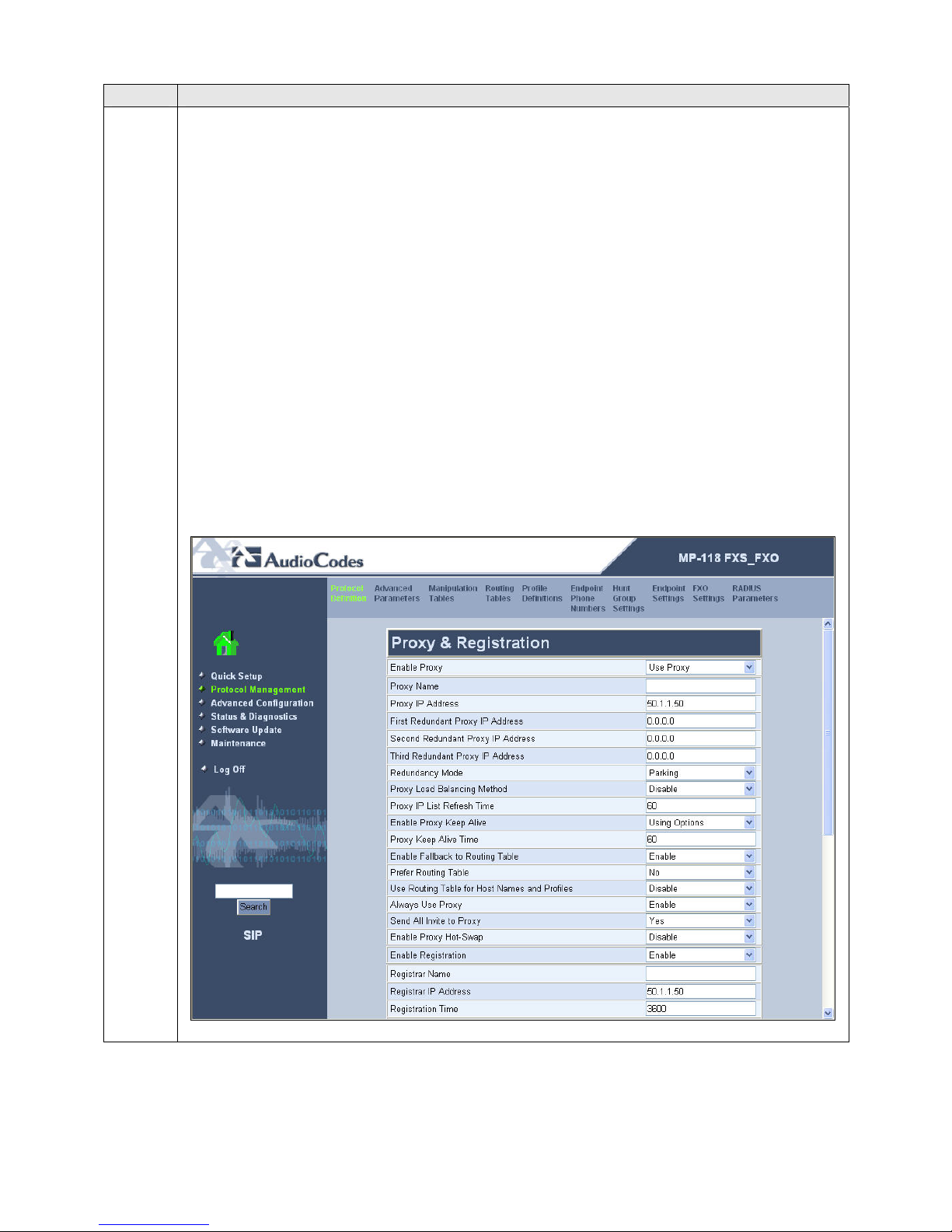
Proxy and Registration
From the menu shown in Step 5, navigate to Protocol Definition Æ Proxy &
Registration. Configure the parameters as described below.
For the Enable Proxy field, select Use Proxy from the pull-down menu.
In the Proxy IP Address field, enter the IP address of the Avaya SES.
For the Enable Proxy Keep Alive field, select Using Options from the pull-
down menu. The MP-118 will use the SIP OPTIONS message as a handshake
mechanism with the Avaya SES to determine if the SIP connection is up. If the
connection is down, the MP-118 will failover to the FXO ports.
For the Always Use Proxy field, select Enabled.
For the Send All Invite to Proxy field, select Yes. This directs the MP-118 to
send all INVITE requests to the Avaya SES, including those generated as the
result of a transfer or redirect.
For the Enable Registration field, select Yes. This will allow the MP-118 to
register the FXS endpoints with the Avaya SES.
In the Registrar IP Address field, enter the IP address of the Avaya SES.
Default values may be retained for all other fields. Scroll down to continue
configuring parameters on the lower half of the screen.
CTM; Reviewed:
SPOC 11/29/2007
Solution & Interoperability Test Lab Application Notes
©2006 Avaya Inc. All Rights Reserved.
26 of 51
AudioCodesMP118.doc
Page 27
Step Description
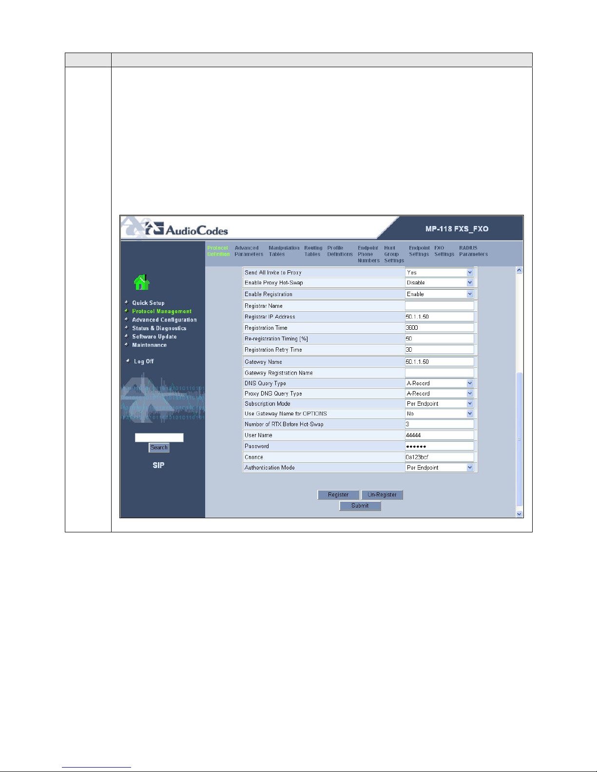
7. Configure the parameters as described below.
In the Gateway Name field, enter the IP address of the Avaya SES.
In this configuration, the MP-118 requires that a separate extension be assigned
to the gateway itself. In the User Name field, enter the extension created for
this purpose in Section 3, Step 18.
In the Password field, enter the password for the above user.
For the Authentication Mode, select Per Endpoint. The MP-118 will
authenticate each endpoint separately.
Click Submit.
CTM; Reviewed:
SPOC 11/29/2007
Solution & Interoperability Test Lab Application Notes
©2006 Avaya Inc. All Rights Reserved.
27 of 51
AudioCodesMP118.doc
Page 28
Step Description
8.
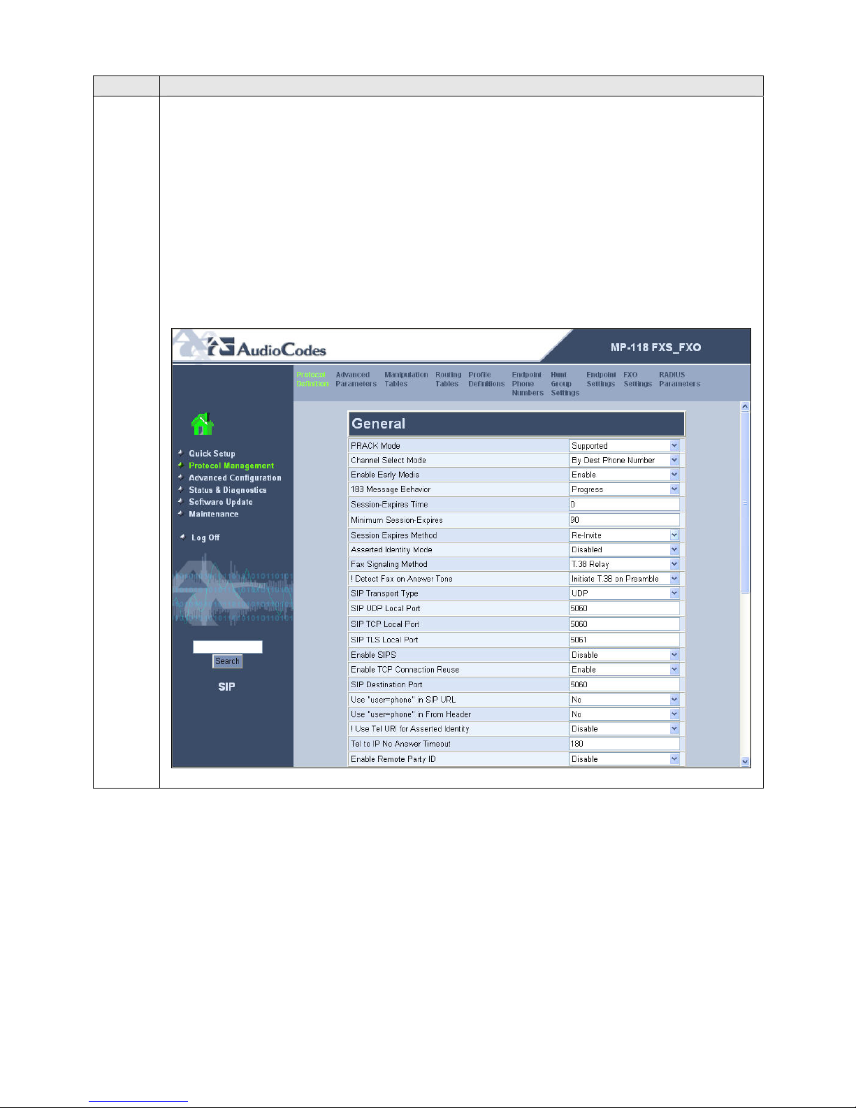
General Protocol Parameters
From the menu shown in Step 5, navigate to Protocol Definition Æ General
Parameters. Configure the parameters as described below.
For the Enable Early Media field, select Enabled. If enabled, the MP-118
sends Session Description Protocol (SDP) information in the 18x responses
allowing the media stream to be set-up prior to answering the call.
If fax support is needed, select T.38 Relay as the Fax Signaling Method.
Select No for the Use “user=phone” in SIP URL field.
Default values may be retained for all other fields. Scroll down to the bottom of the
page and click Submit (not shown).
CTM; Reviewed:
SPOC 11/29/2007
Solution & Interoperability Test Lab Application Notes
©2006 Avaya Inc. All Rights Reserved.
28 of 51
AudioCodesMP118.doc
Page 29
Step Description
9.
Codecs
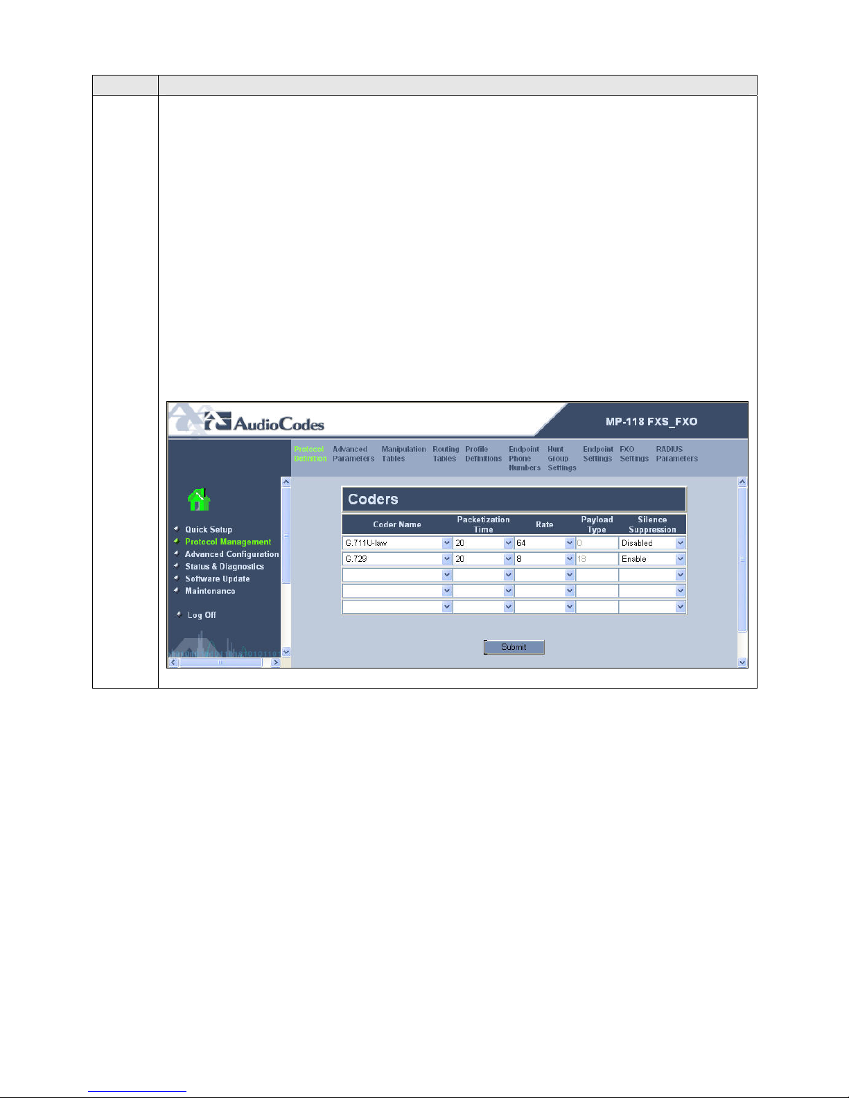
From the menu shown in Step 5, navigate to Protocol Definition Æ Coders. In the
screen below, select the list of preferred codecs to be used by the MP-118 with the
most preferred codec at the top and working downward to the least preferred. This list
must have an overlap with the list provided on Avaya Communication Manager in
Section 3, Step 4. The codec is selected from the pull-down menu under the Coder
Name field.
The codec list used for the compliance test is shown in the example below. G.711U-
law was selected as the most preferred followed by G.729. For the G.729 codec, the
Silence Suppression field was set to Enable. With silence suppression enabled, the
MP-118 uses the equivalent of a G.729AB codec. Default values were retained for all
other fields.
Click Submit.
CTM; Reviewed:
SPOC 11/29/2007
Solution & Interoperability Test Lab Application Notes
©2006 Avaya Inc. All Rights Reserved.
29 of 51
AudioCodesMP118.doc
Page 30
Step Description
10.
DTMF and Dialing
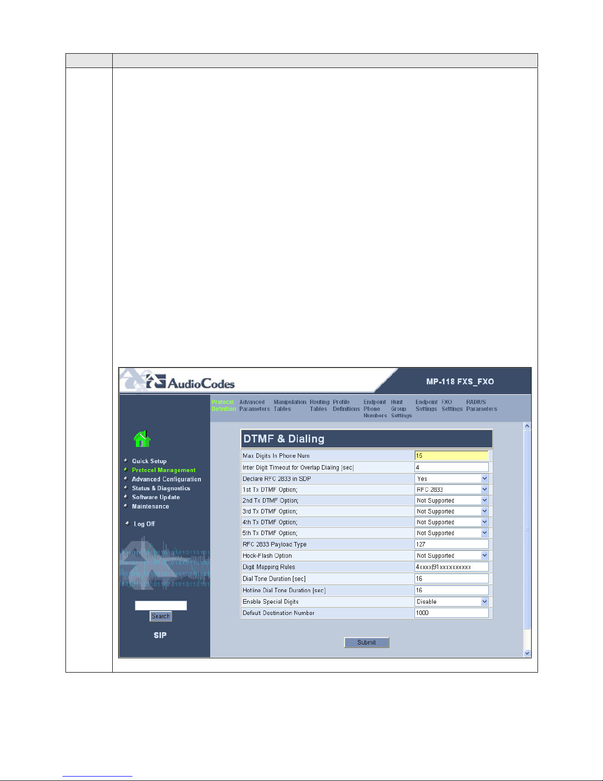
From the menu shown in Step 5, navigate to Protocol Definition Æ DTMF &
Dialing. Configure the parameters as described below.
In the Max Digits in Phone Num field, enter the maximum number of digits
that can be dialed.
For the Declare RFC 2833 in SDP field, select Yes.
For the 1st Tx DTMF Option field, select RFC 2833. This selects RFC 2833 as
the preferred DTMF transmission method.
Select 127 as the RFC 2833 Payload Type to match the value used by the
Avaya SIP Telephones. Media may not be redirected (shuffled) in all scenarios
from Avaya Communication Manager to the endpoints if this value is not the
same as the SIP Telephones.
Assign the digit map pattern to the Digit Mapping Rules field. If the dialed
digits matches any pattern in the digit map, the MP-118 stops collecting digits
and places the call. The digit map may contain up to 52 patterns each separated
by a vertical bar (|). The maximum length of the entire digit map is limited to
152 characters. For the compliance test, two patterns were defined. One pattern
matches any 5 digit number beginning with 4 (4xxxx). The other pattern
matches any 12 digit number starting with 91 (91xxxxxxxxxx)
Default values may be retained for all other fields. Click Submit.
CTM; Reviewed:
SPOC 11/29/2007
Solution & Interoperability Test Lab Application Notes
©2006 Avaya Inc. All Rights Reserved.
30 of 51
AudioCodesMP118.doc
Page 31
Step Description
11.
Advanced Parameters
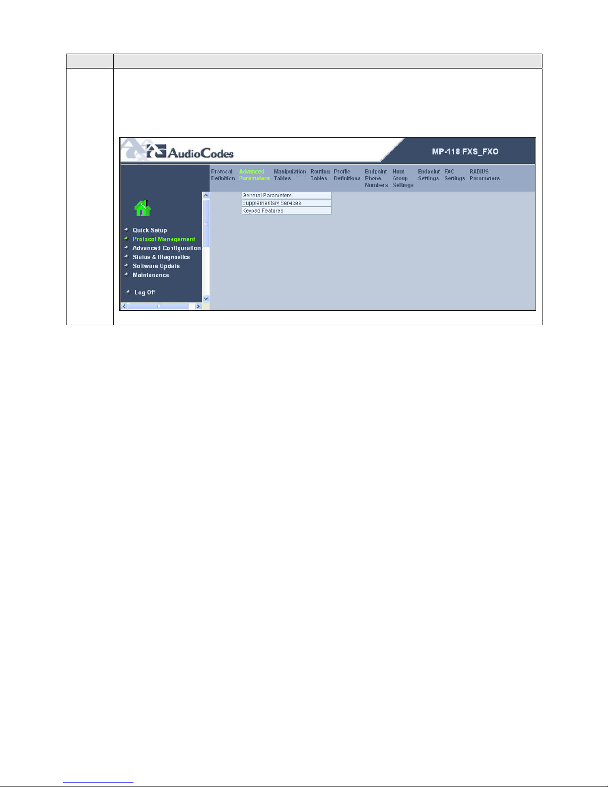
To access these parameters, select Protocol Management in the left pane and navigate
to Advanced Parameters in the right pane. The pull-down choices for Advanced
Parameters are shown below.
CTM; Reviewed:
SPOC 11/29/2007
Solution & Interoperability Test Lab Application Notes
©2006 Avaya Inc. All Rights Reserved.
31 of 51
AudioCodesMP118.doc
Page 32
Step Description
12.
General Advanced Parameters
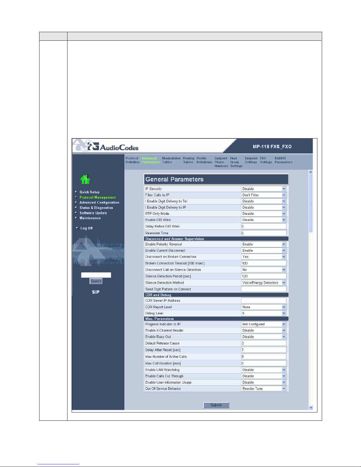
From the menu shown in Step 11, navigate to Advanced Parameters Æ General
Parameters. Configure the parameters as described below.
Select Enable for the Enable Polarity Reversal and Enable Current
Disconnect fields. This will allow the MP-118 to provide the proper
disconnect indication to various line types.
In the Max Number of Active Calls field, enter a value that is equal to or
greater than the maximum number of ports (FXS + FXO) available on the
gateway. For the compliance test, there were 4 FXS ports and 4 FXO ports.
Default values may be retained for all other fields. Click Submit.
CTM; Reviewed:
SPOC 11/29/2007
Solution & Interoperability Test Lab Application Notes
©2006 Avaya Inc. All Rights Reserved.
32 of 51
AudioCodesMP118.doc
Page 33
Step Description
13.
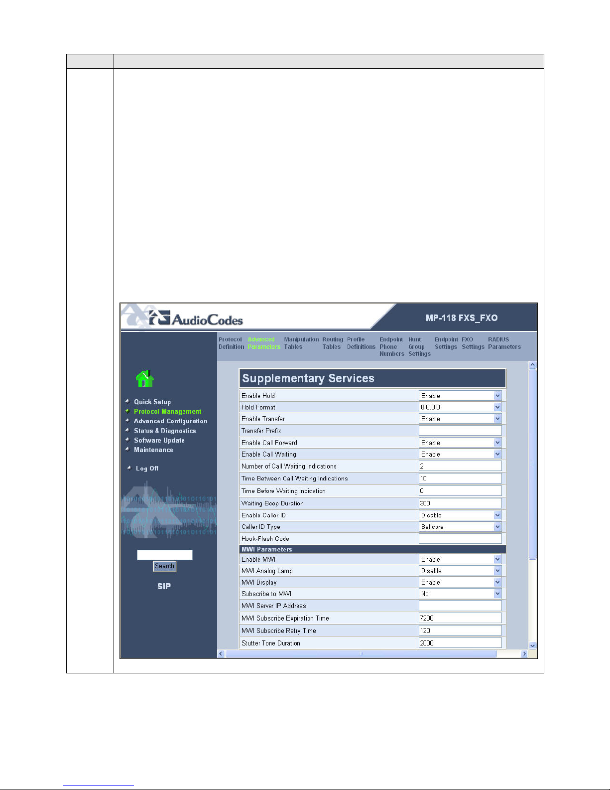
Supplementary Services
From the menu shown in Step 11, navigate to Advanced Parameters Æ
Supplementary Services. Configure the parameters as described below.
If the analog phones connected to the MP-118 support Caller ID then set the
Enable Caller ID field to Enabled. For the compliance test, this field was set
to Disabled since none of the analog phones used had a Caller ID display.
Caller ID can also be controlled on a per port basis by navigating to Protocol
Management Æ Endpoint Settings Æ Generate Caller ID to Tel Table (not
shown here).
Select Enabled for the Enable MWI and MWI Display fields if the analog
phones support a visual MWI indicator. For the compliance test, even though
these fields were enabled, MWI was only tested for stutter dial tone.
Hold, Transfer, Call Forwarding and Call Waiting are enabled by default.
Default values may be retained for all other fields. Scroll down to the bottom of the
page and click Submit (not shown).
CTM; Reviewed:
SPOC 11/29/2007
Solution & Interoperability Test Lab Application Notes
©2006 Avaya Inc. All Rights Reserved.
33 of 51
AudioCodesMP118.doc
Page 34
Step Description
14.
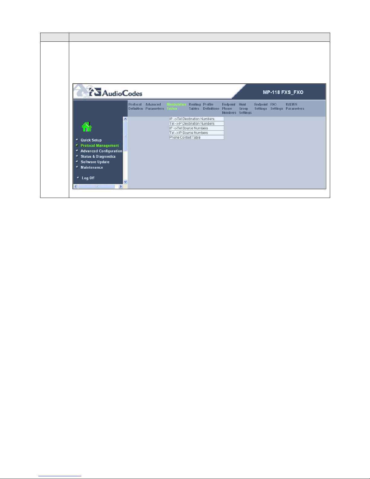
Manipulation Tables
To access these parameters, select Protocol Management in the left pane and navigate
to Manipulation Tables in the right pane. The pull-down choices for the
Manipulation Tables are shown below.
CTM; Reviewed:
SPOC 11/29/2007
Solution & Interoperability Test Lab Application Notes
©2006 Avaya Inc. All Rights Reserved.
34 of 51
AudioCodesMP118.doc
Page 35
Step Description
15.
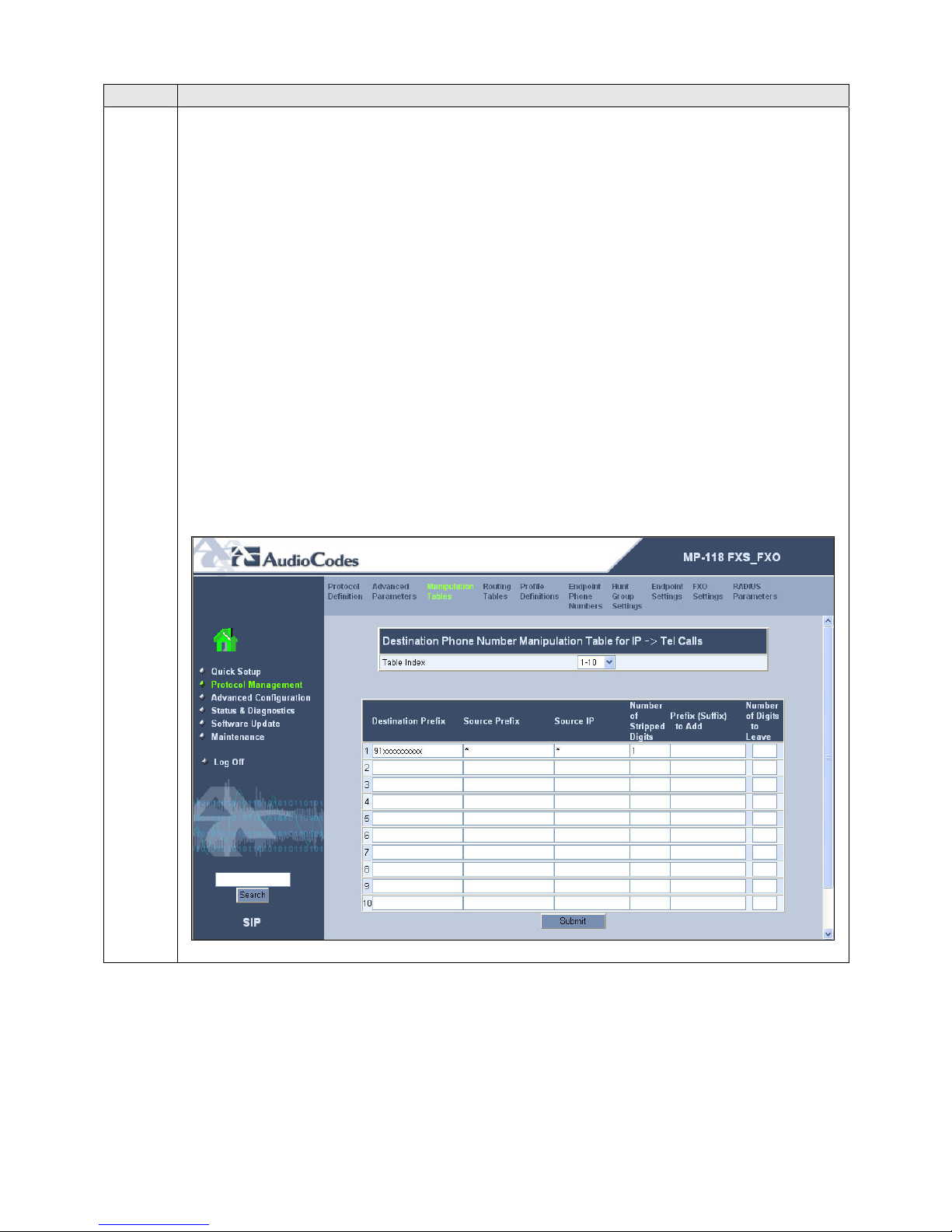
IP to Telephone Destination Numbers
From the menu shown in Step 14, navigate to Manipulation Tables Æ IP to Tel
Destination Numbers.
This table defines the digit manipulation that will be performed on IP to telephony
calls. The Destination Prefix, Source Prefix and Source IP columns define which
calls to manipulate. The 3 remaining columns define the digit manipulation to apply to
these calls. In the example below, all calls dialed with twelve digits beginning with 91
coming from any source extension and source IP will have the first digit stripped off.
This manipulation is required to allow the branch user to dial the same outbound
number when the data WAN is available or not. Under normal conditions, a user dials
9 + the 11-digit PSTN number for an outbound call. The call is forwarded to the
Avaya Communication Manager where the 9 is stripped off before being routed to the
PSTN. If the data WAN is unavailable, the call is still originated as an IP call but can
not be sent to the Main site. The MP-118 will use the table shown below to strip the
preceding 9 off of this IP call before routing it to the FXO port for the PSTN.
Click Submit.
CTM; Reviewed:
SPOC 11/29/2007
Solution & Interoperability Test Lab Application Notes
©2006 Avaya Inc. All Rights Reserved.
35 of 51
AudioCodesMP118.doc
Page 36
Step Description
16.
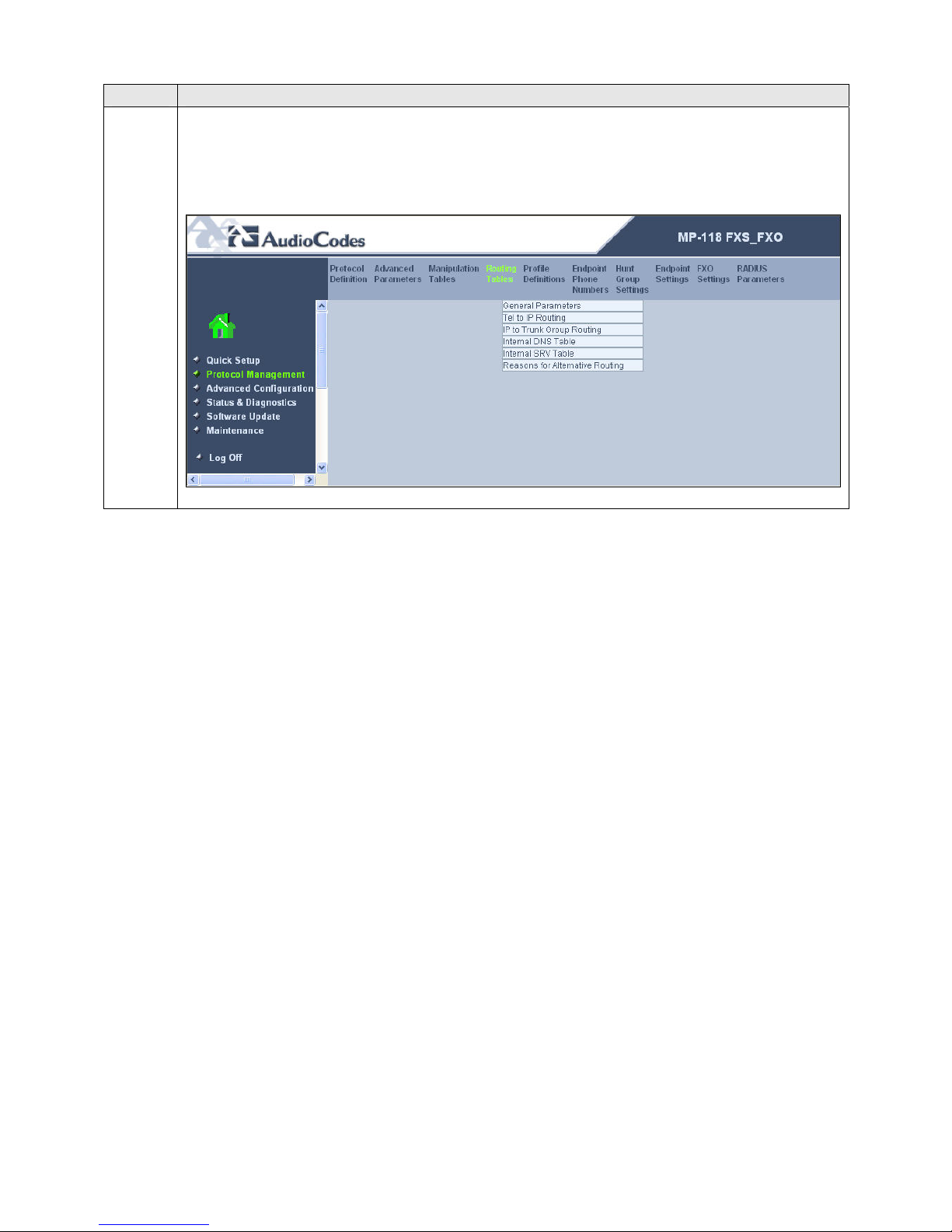
Routing Tables
To access these parameters, select Protocol Management in the left pane and navigate
to Routing Tables in the right pane. The pull-down choices for the Routing Tables
are shown below.
CTM; Reviewed:
SPOC 11/29/2007
Solution & Interoperability Test Lab Application Notes
©2006 Avaya Inc. All Rights Reserved.
36 of 51
AudioCodesMP118.doc
Page 37
Step Description
17.
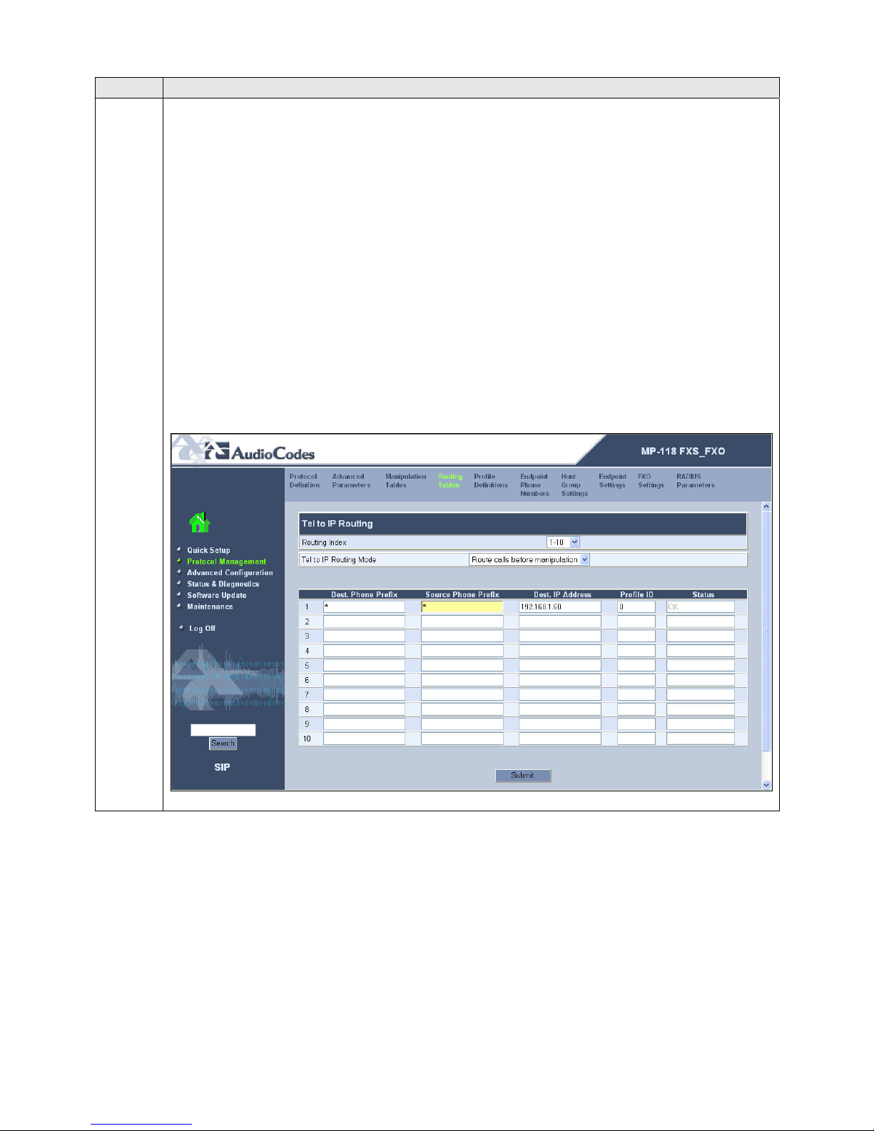
Telephony to IP Routing
From the menu shown in Step 16, navigate to Routing Tables Æ Tel to IP Routing.
This table defines the mapping of analog calls to an IP address that will process the IP
leg of the call if the proxy defined in Step 6 (Avaya SES) is not available. The Dest.
Phone Prefix and Source Phone Prefix columns define which calls are mapped to the
IP address in the Dest. IP Address column.
In the example below, the table entry maps calls from any destination prefix, or any
source prefix to IP address 192.168.1.60 which is the address of the MP-118. When
the MP-118 processes the call, the MP-118 will use the table in Step 18 to route the
call to a FXO port. Thus, Steps 17 – 18 provide the routing necessary to support the
failover functionality to the PSTN. The default values may be used for the Profile ID
column.
Click Submit.
CTM; Reviewed:
SPOC 11/29/2007
Solution & Interoperability Test Lab Application Notes
©2006 Avaya Inc. All Rights Reserved.
37 of 51
AudioCodesMP118.doc
Page 38
Step Description
18.
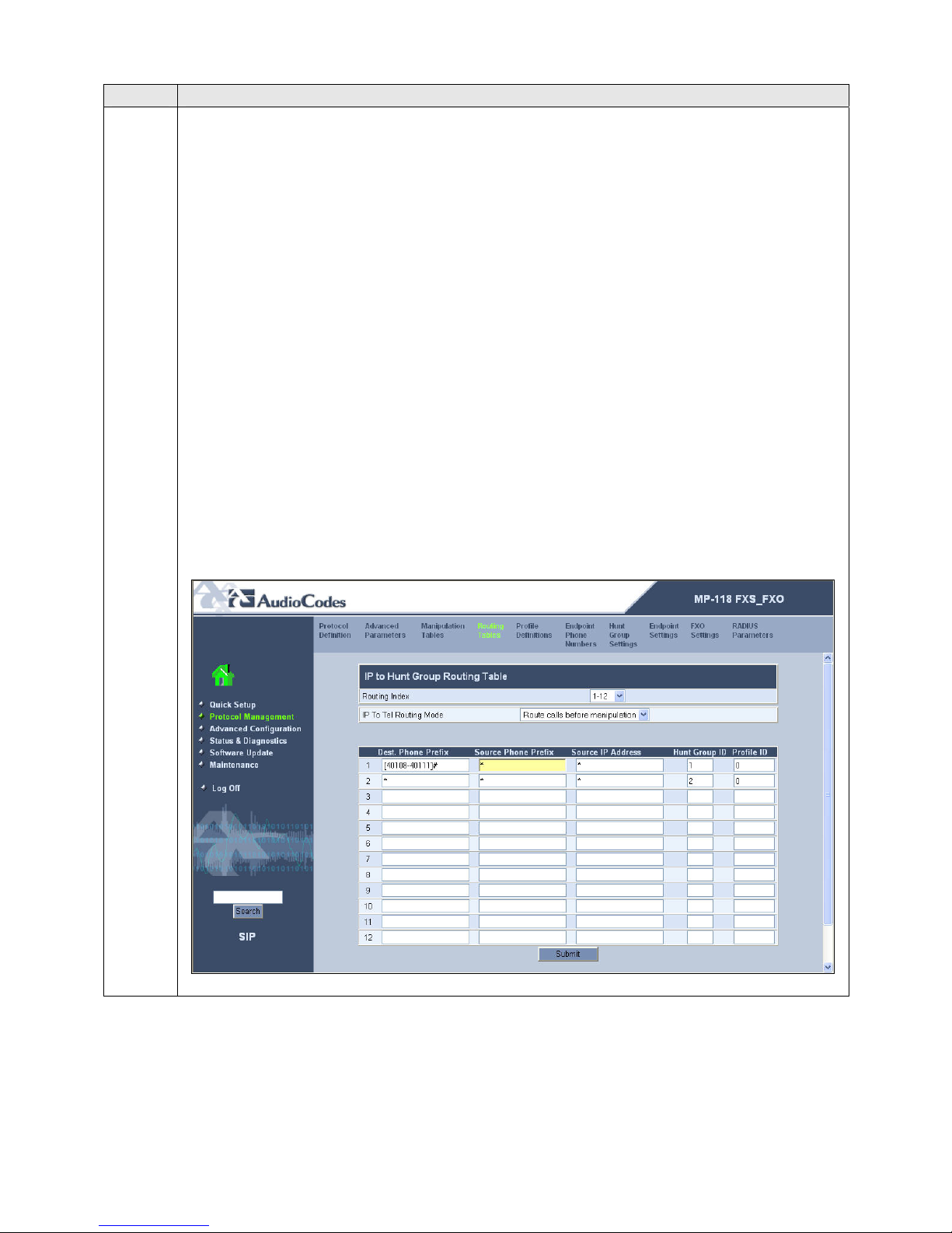
IP to Hunt Group Routing Table
From the menu shown in Step 16, navigate to Routing Tables Æ IP to Trunk Group
Routing.
This table defines the mapping of IP calls to a group of channels or “hunt group”. In
Step 19, the FXS ports are assigned to hunt group 1 and the FXO ports are assigned to
hunt group 2. The Dest. Phone Prefix, Source Phone Prefix and Source IP Address
columns define which calls are mapped to the hunt group in the Hunt Group ID
column. In the first entry in the example below, all calls to any extension 40108 40111 from any source extension and source IP will be routed to hunt group 1. The #
at the end of the Dest. Phone Prefix field indicates “end of number”. Thus, the dialed
number must be an exact match with an extension and not simply a match on the prefix
of 40108 - 40111.
The second entry routes any other call to hunt group 2. Even though Avaya
Communication Manager will not route any other calls to the MP-118 except calls to
the extensions 40108 – 40111, this entry is needed for the failover case. If a user dials
an outbound number and it can not reach the main site, this table will direct the call to
hunt group 2 which contains the FXO ports.
Click Submit.
CTM; Reviewed:
SPOC 11/29/2007
Solution & Interoperability Test Lab Application Notes
©2006 Avaya Inc. All Rights Reserved.
38 of 51
AudioCodesMP118.doc
Page 39
Step Description
19.
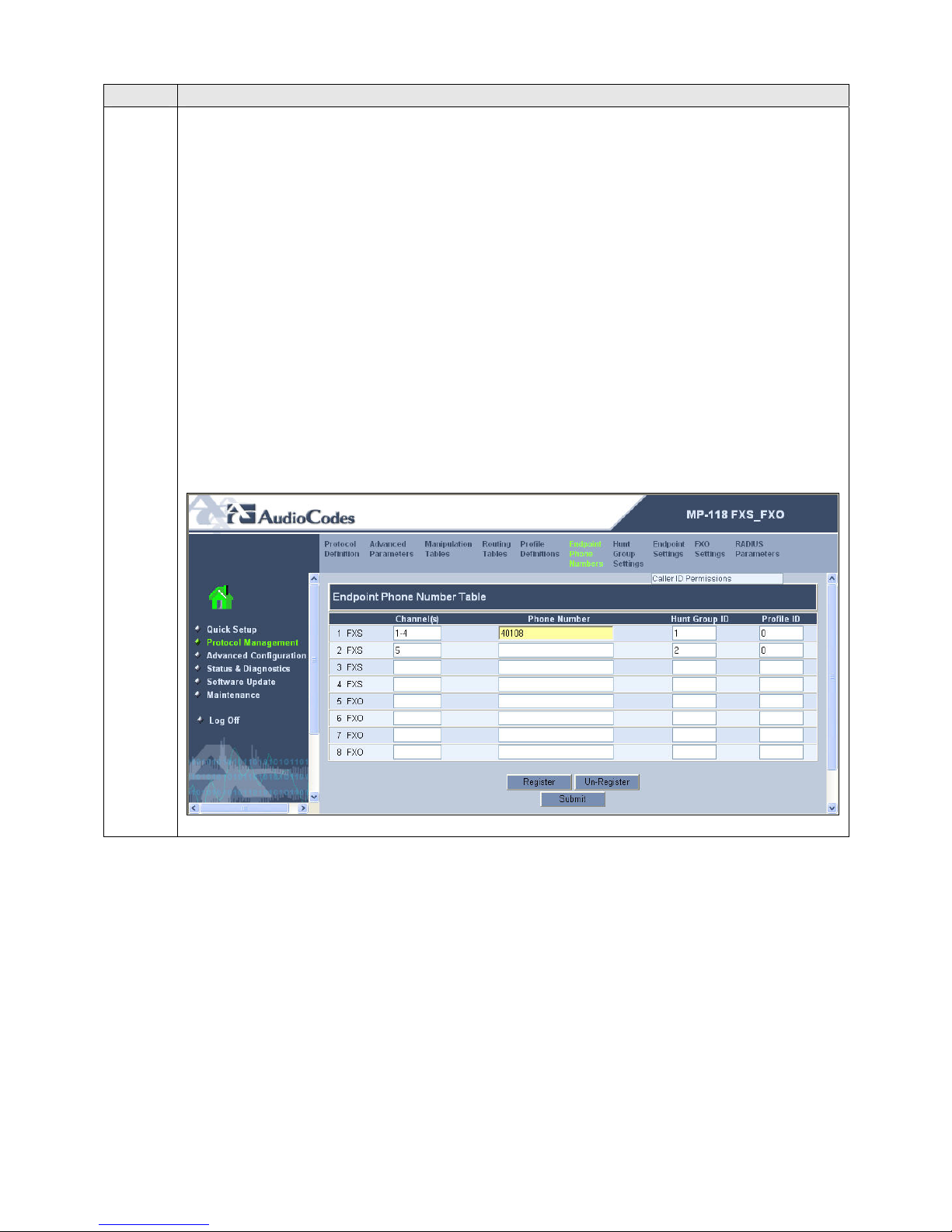
Endpoint Phone Numbers
Select Protocol Management in the left pane and navigate to Endpoint Phone
Numbers in the right pane.
The Endpoint Phone Number Table maps a particular channel/port to a phone number
and hunt group. In the Channel(s) column, enter a range of channels to be assigned.
In the Phone Number column, enter the starting extension for the range of extensions.
In the Hunt Group ID column, enter the hunt group that contains these extensions.
In the example below, the first entry assigns channels 1 – 4 with extensions 40108 –
40111 to hunt group 1. The second entry assigns channel 5 (the first FXO port) to hunt
group 2. Since only the first FXO port was connected to the PSTN, only channel 5 was
enter in this table. The Phone Number field is blank for this entry. The originating
number for calls originating from channel 5 is set to the Caller ID information received
from the PSTN trunk.
Click Submit.
CTM; Reviewed:
SPOC 11/29/2007
Solution & Interoperability Test Lab Application Notes
©2006 Avaya Inc. All Rights Reserved.
39 of 51
AudioCodesMP118.doc
Page 40
Step Description
20.
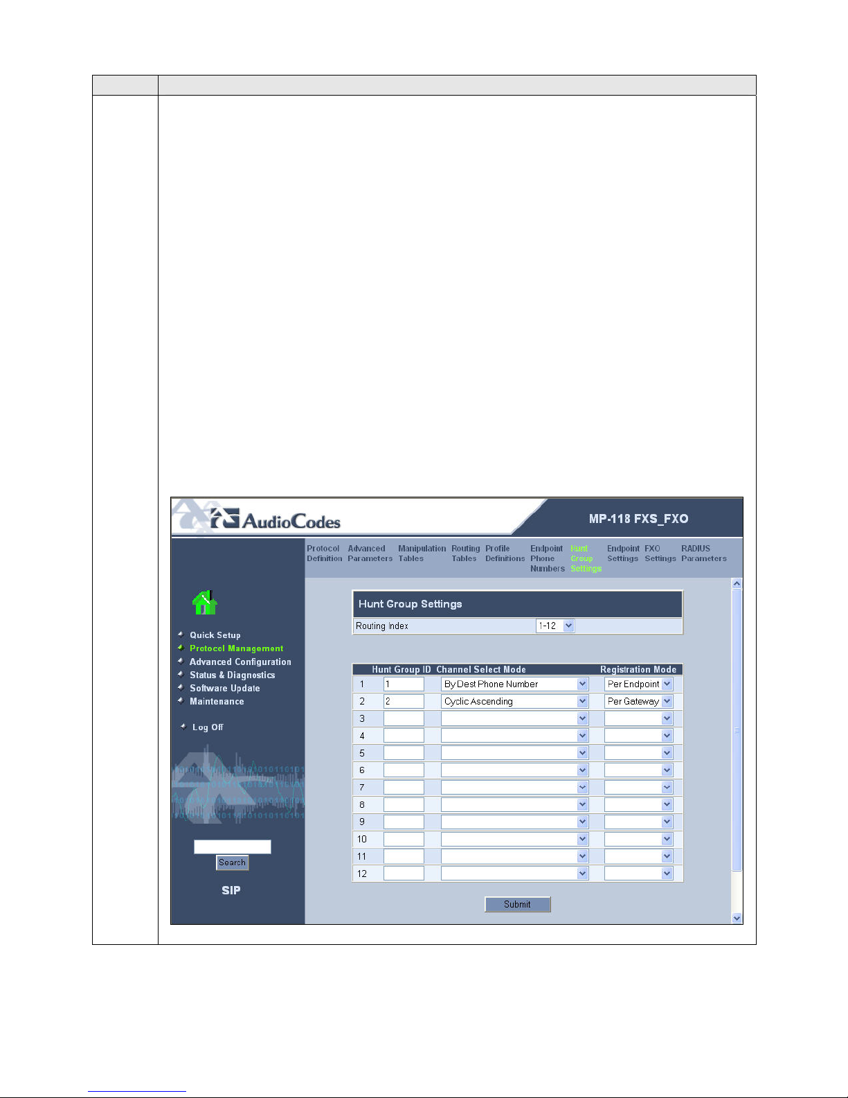
Hunt Group Settings
Select Protocol Management in the left pane and navigate to Hunt Group Settings in
the right pane.
Configure the parameters are described below.
For Hunt Group ID 1 which contain the FXS (endpoint) ports, select the
Channel Select Mode as By Dest Phone Number. Thus, each port in this hunt
group will only be selected if its destination phone number is dialed. Select the
Registration Mode to be Per Endpoint.
For Hunt Group ID 2 which contain the FXO (POTS) ports, select the
Channel Select Mode as Cyclic Ascending. The ports in this hunt group are
treated as a pool, and each will be selected in cyclic ascending order. Select the
Registration Mode to be Per Gateway. This allows the MP-118 to register
once for all the FXO ports using the gateway extension entered in Step 7. The
MP-118 requires that both the FXS and FXO ports be registered since
registration was enabled in Step 6. For the compliance test, it was chosen to
register once for all the FXO ports since it is not intended that the FXO ports be
accessed using the gateway extension.
Click Submit.
CTM; Reviewed:
SPOC 11/29/2007
Solution & Interoperability Test Lab Application Notes
©2006 Avaya Inc. All Rights Reserved.
40 of 51
AudioCodesMP118.doc
Page 41
Step Description
21.
Endpoint Settings
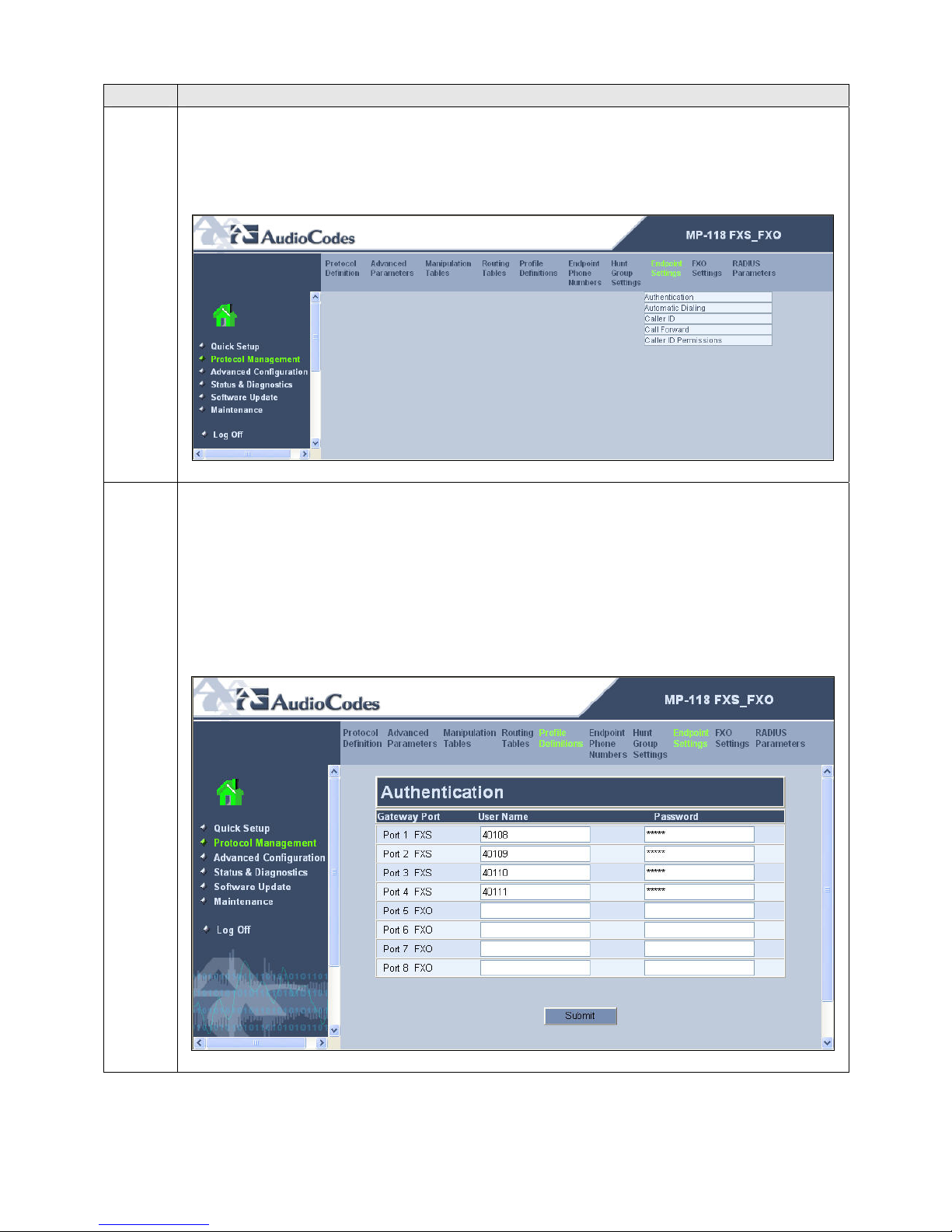
To access these parameters, select Protocol Management in the left pane and navigate
to Endpoint Settings in the right pane. The pull-down choices for Endpoint Settings
are shown below.
22.
Authentication
From the menu shown in Step 21, navigate to Endpoint Settings Æ Authentication.
The Authentication page defines a username and password combination for
authentication of each MP-118 port with the Avaya SES. Enter a User Name and
Password that matches the values configured on Avaya SES in Section 4, Step 7.
Click Submit.
CTM; Reviewed:
SPOC 11/29/2007
Solution & Interoperability Test Lab Application Notes
©2006 Avaya Inc. All Rights Reserved.
41 of 51
AudioCodesMP118.doc
Page 42
Step Description
23.
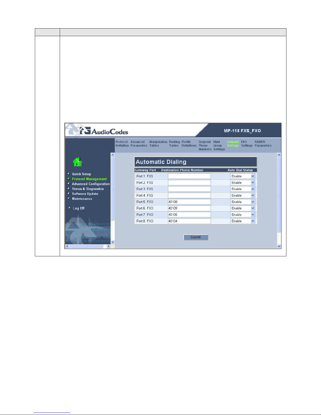
Automatic Dialing
From the menu shown in Step 21, navigate to Endpoint Settings Æ Automatic
Dialing.
The Automatic Dialing page provides the mapping of incoming calls on the FXO ports
to a branch extension when the data WAN is unavailable. In the example below, each
FXO port is mapped to a different extension at the branch location. All ports were
mapped even though only one FXO port was connected. The destination extension is
placed in the Destination Phone Number column.
Click Submit.
CTM; Reviewed:
SPOC 11/29/2007
Solution & Interoperability Test Lab Application Notes
©2006 Avaya Inc. All Rights Reserved.
42 of 51
AudioCodesMP118.doc
Page 43
Step Description
24.
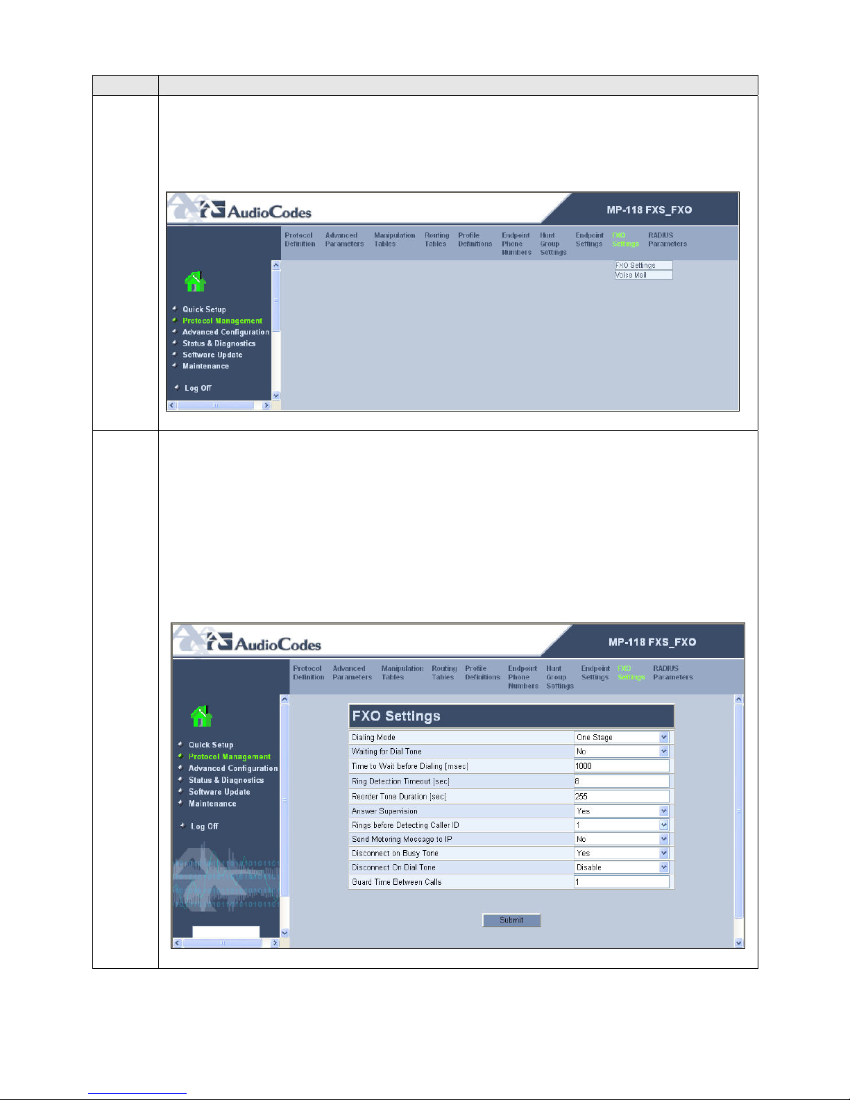
FXO Settings
To access these parameters, select Protocol Management in the left pane and navigate
to FXO Settings in the right pane. The pull-down choices for FXO Settings are
shown below.
25.
FXO Settings
From the menu shown in Step 24, navigate to FXO Settings Æ FXO Settings.
Configure the parameters as described below.
Select One Stage for the Dialing Mode. The MP-118 will not prompt the user
with a second dial tone and will send all digits in a single request including any
access code prefix.
Select Yes for Answer Supervision.
Default values may be retained for all other fields. Click Submit.
CTM; Reviewed:
SPOC 11/29/2007
Solution & Interoperability Test Lab Application Notes
©2006 Avaya Inc. All Rights Reserved.
43 of 51
AudioCodesMP118.doc
Page 44
Step Description
26.
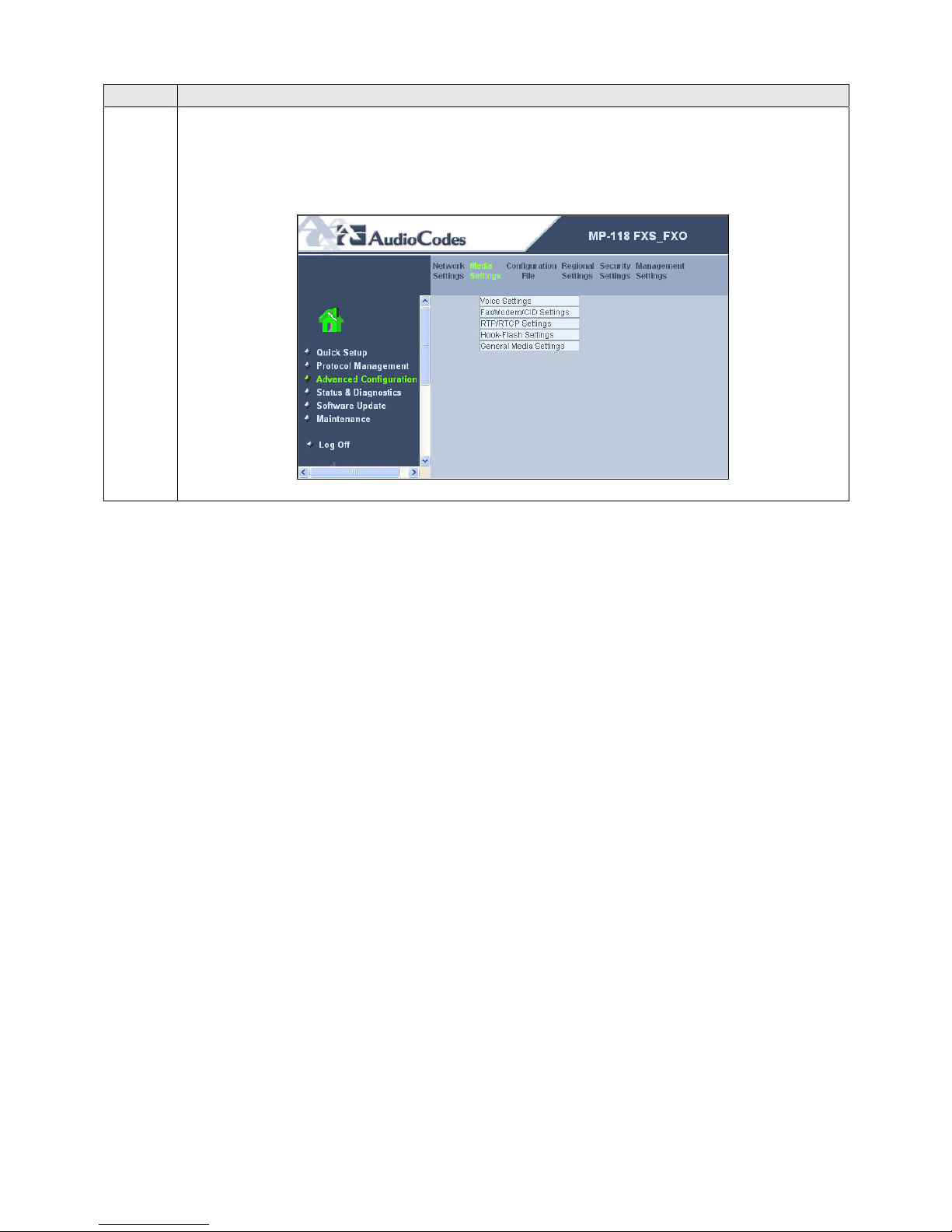
Media Settings
To access these parameters, select Advanced Configuration in the left pane and
navigate to Media Settings in the right pane. The pull-down choices for Media
Settings are shown below.
CTM; Reviewed:
SPOC 11/29/2007
Solution & Interoperability Test Lab Application Notes
©2006 Avaya Inc. All Rights Reserved.
44 of 51
AudioCodesMP118.doc
Page 45
Step Description
27.
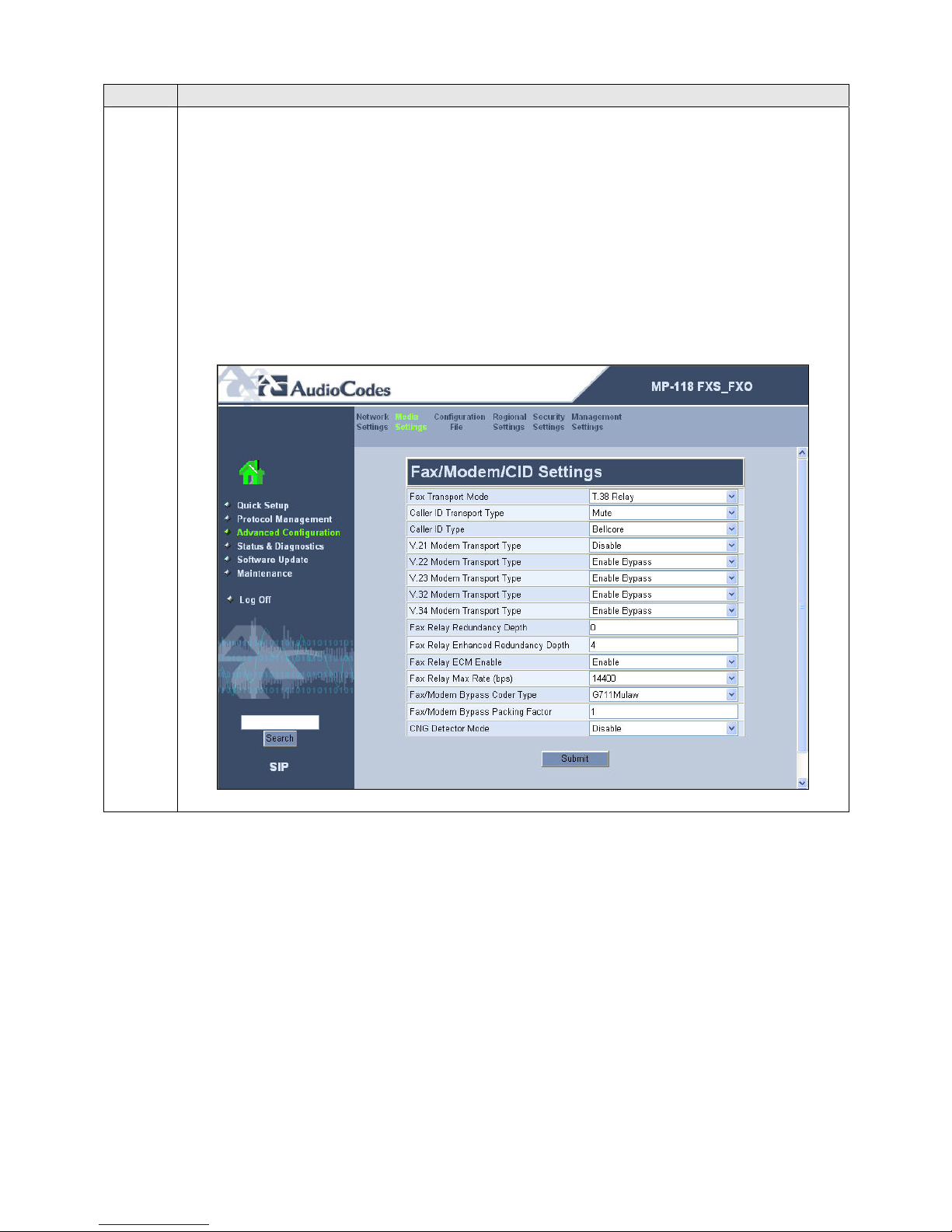
Fax/Modem/CID Settings
From the menu shown in Step 26, navigate to Media Settings Æ Fax/Modem/CID
Settings. Configure the parameters as described below.
Select T.38 Relay for the Fax Transport Mode to support faxing across the
data WAN.
Select Enable Bypass for the V.22 – V.34 Modem Transport Types to
support modem calls over SIP planned in future Avaya Communication
Manager releases.
Select G711Mulaw for the Fax/Modem Bypass Coder Type.
Default values may be retained for all other fields. Click Submit.
CTM; Reviewed:
SPOC 11/29/2007
Solution & Interoperability Test Lab Application Notes
©2006 Avaya Inc. All Rights Reserved.
45 of 51
AudioCodesMP118.doc
Page 46
Step Description
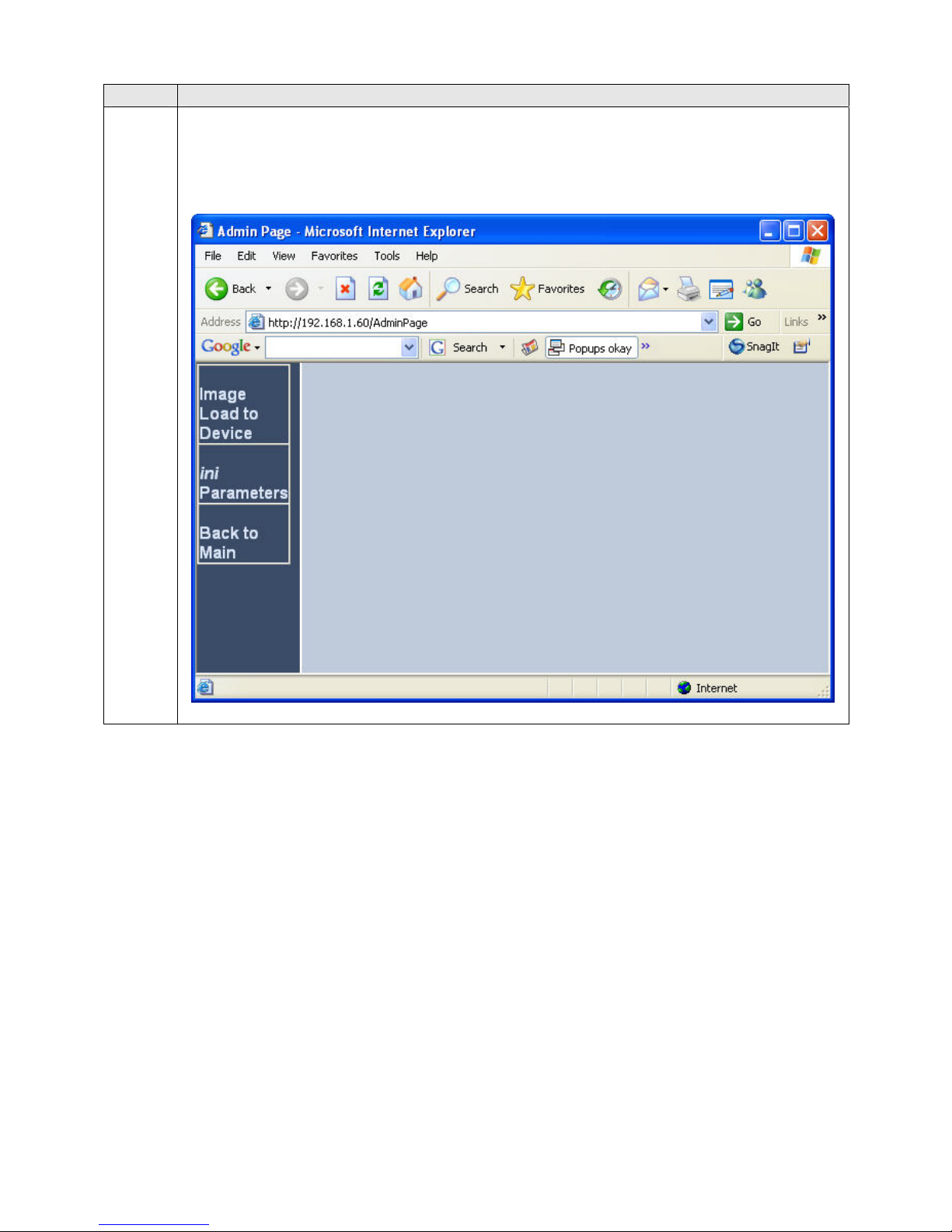
28. For proper modem interoperability over SIP planned for future Avaya Communication
Manager releases, an additional parameter must be changed in the ini file. From a web
browser, enter <ip_address>/AdminPage in the Address field where <ip_address> is
the IP address of the MP-118. The main page will appear as shown below.
CTM; Reviewed:
SPOC 11/29/2007
Solution & Interoperability Test Lab Application Notes
©2006 Avaya Inc. All Rights Reserved.
46 of 51
AudioCodesMP118.doc
Page 47
Step Description
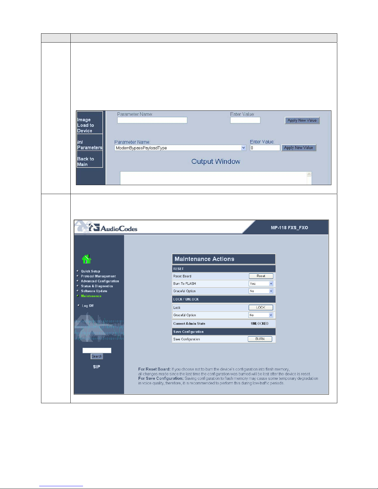
29. Navigate to ini Parameters in the left pane. In the Parameter Name field, select
ModemBypassPayloadType from the pull-down menu. Enter 0 in the Enter Value
field. Click on Apply New Value.
A value of 0 in the payload type indicates a G.711mu call. By default, the MP-118
uses a proprietary value for the payload type of modem calls so they can be
distinguished from other G.711mu calls.
30. To save the configuration, return to the administrative web page and select
Maintenance in the left pane. Click the BURN button.
CTM; Reviewed:
SPOC 11/29/2007
Solution & Interoperability Test Lab Application Notes
©2006 Avaya Inc. All Rights Reserved.
47 of 51
AudioCodesMP118.doc
Page 48

6. Interoperability Compliance Testing
This section describes the compliance testing used to verify the interoperability between the
AudioCodes MP-118, Avaya SIP Enablement Services (SES) and Avaya Communication Manager.
This section covers the general test approach and the test results.
6.1. General Test Approach
The general test approach was to make calls to/from the telephones connected through the MP-118
at the branch site using various codec settings and exercising common PBX features. This testing
included the analog telephones, and Avaya SIP telephones. The calls were made to/from the main
site, the PSTN and within the branch site. The same test cases, where applicable, were repeated with
a simulated data WAN outage.
6.2. Test Results
The AudioCodes MP-118 successfully passed compliance testing. The following features and
functionality were verified using an MP-118 analog endpoint when the data WAN was available.
Calls to/from the main site
Calls to/from the PSTN
Intra-branch calls
G.711mu and G.729AB codec support
Proper recognition of DTMF transmissions
Local device support for Hold, Transfer, and Call Waiting
Proper operation of voicemail with message waiting indicators (MWI). For the analog
phones, MWI was provided via stutter dial tone.
Call Forwarding provided by Avaya Communication Manager.
Conferencing (Avaya SIP telephone initiates a conference that includes an MP-118 analog
endpoint)
Extended telephony features using Avaya Communication Manager Feature Name
Extensions such as Conference On Answer, Call Park, Call Pickup, Automatic Redial and
Send All Calls. For more information on FNEs, please refer to [6].
T.38 fax support
Proper system recovery after a MP-118 restart
The following features and functionality were verified using an MP-118 analog endpoint when a
simulated data WAN failure was introduced.
Automatic failover to the POTS line to complete calls to the main site and PSTN using full
11 digit dialing. Incoming calls to the branch are limited to the single POTS number
assigned to the branch.
Intra-branch calls
Local device support for Hold, Transfer, and Call Waiting
The following observations were made during the compliance test:
The analog endpoints connected to the MP-118 do not support initiating a conference call.
When the data WAN is unavailable and an MP-118 analog endpoint calls the PSTN and does
an unattended transfer to another MP-118 analog endpoint, the originator of the transfer does
not hear ringback.
CTM; Reviewed:
SPOC 11/29/2007
Solution & Interoperability Test Lab Application Notes
©2006 Avaya Inc. All Rights Reserved.
48 of 51
AudioCodesMP118.doc
Page 49

When using the Call Park feature from an MP-118 analog endpoint via the Avaya
Communication Manager FNE, the user is required to wait a couple of seconds before
hanging up after hearing the feature confirmation tones. Otherwise, the MP-118 does not
disconnect the call as expected but instead attempts a transfer.
To support T.38 faxing with the MP-118, a non-GA release of Avaya Communication
Manager was required.
7. Verification Steps
The following steps may be used to verify the configuration:
• From the Avaya Communication Manager SAT, use the status signaling-group command to
verify that the SIP signaling group is in-service.
• From the Avaya Communication Manager SAT, use the status trunk-group command to
verify that the SIP trunk group is in-service.
• From the Avaya SES web administration interface, verify that all endpoints behind the MP-
118 are registered with the Avaya SES.
• Verify that calls can be placed to/from the analog endpoints behind the MP-118 and the main
branch.
• Verify that calls can be placed to/from the analog endpoints behind the MP-118 and the
PSTN.
• Verify that calls can be placed from the analog endpoints behind the MP-118 when a
simulated data WAN failure is introduced.
8. Support
For technical support on the MP-118, contact AudioCodes via the support link at
www.audiocodes.com.
9. Conclusion
These Application Notes describe the procedures required to configure the AudioCodes MP-118
Analog VoIP Gateway to interoperate with Avaya SIP Enablement Services and Avaya
Communication Manager. The AudioCodes MP-118 successfully passed compliance testing with
the observations documented in Section 6.2.
10. Additional References
[1] Feature Description and Implementation For Avaya Communication Manager, Doc # 555-245-
205, Issue 4.0, February 2006.
[2] Administrator Guide for Avaya Communication Manager, Doc # 03-300509, Issue 2.1, May
2006
[3] Avaya Communication Manager Advanced Administration Quick Reference, Doc # 03-300364,
Issue 2, June 2005 Release 3.0
[4] Avaya IA 770 INTUITY AUDIX Messaging Application, Doc # 11-300532, May 2005
[5] Installing and Administering SIP Enablement Services R3.1, Doc# 03-600768, Issue 1.5,
February 2006
[6] Avaya Extension to Cellular and Off-PBX Station (OPS) Installation and Administration Guide
Release 3.0, version 6.0, Doc # 210-100-500, Issue 9, June 2005
[7] LTRT-59802 MediaPack Fast Track Installation Guide, Version 5.0.
CTM; Reviewed:
SPOC 11/29/2007
Solution & Interoperability Test Lab Application Notes
©2006 Avaya Inc. All Rights Reserved.
49 of 51
AudioCodesMP118.doc
Page 50

[8] LTRT-65406 MediaPack SIP User’s Manual, Version 5.0.
[9] LTRT-65607 MediaPack & Mediant 1000 SIP Analog Gateways Release Notes, Version 5.0.
Product documentation for Avaya products may be found at http://support.avaya.com.
Product documentation for AudioCodes MP-118 Analog VoIP Gateway products may be found at
http://www.audiocodes.com.
CTM; Reviewed:
SPOC 11/29/2007
Solution & Interoperability Test Lab Application Notes
©2006 Avaya Inc. All Rights Reserved.
50 of 51
AudioCodesMP118.doc
Page 51

©
2006 Avaya Inc. All Rights Reserved.
Avaya and the Avaya Logo are trademarks of Avaya Inc. All trademarks identified by ® and ™
are registered trademarks or trademarks, respectively, of Avaya Inc. All other trademarks are the
property of their respective owners. The information provided in these Application Notes is
subject to change without notice. The configurations, technical data, and recommendations
provided in these Application Notes are believed to be accurate and dependable, but are
presented without express or implied warranty. Users are responsible for their application of any
products specified in these Application Notes.
Please e-mail any questions or comments pertaining to these Application Notes along with the
full title name and filename, located in the lower right corner, directly to the Avaya
DeveloperConnection Program at [email protected].
CTM; Reviewed:
SPOC 11/29/2007
Solution & Interoperability Test Lab Application Notes
©2006 Avaya Inc. All Rights Reserved.
51 of 51
AudioCodesMP118.doc
 Loading...