

Avaya AP-7 User Manual

Avaya Wireless AP-7 User Guide
Release 2.5
Document No. 21-300318
September 2004
Issue 1

Copyright 2004, Avaya Inc.
All Rights Reserved
Notice
Every effort was made to ensure that the information in this document
was complete and accurate at the time of printing. However, information
is subject to change.
Warranty
Avaya Inc. provides a limited warranty on this product. Refer to your
sales agreement to establish the terms of the limited warranty. In
addition, Avaya’s standard warranty language as well as information
regarding support for this product, while under warranty, is available
through the following Web site: http://www.avaya.com/support
Preventing Toll Fraud
“Toll fraud” is the unauthorized use of your telecommunications system
by an unauthorized party (for example, a person who is not a corporate
employee, agent, subcontractor, or is not working on your company's
behalf). Be aware that there may be a risk of toll fraud associated with
your system and that, if toll fraud occurs, it can result in substantial
additional charges for your telecommunications services.
Avaya Fraud Intervention
If you suspect that you are being victimized by toll fraud and you need
technical assistance or support, in the United States and Canada, call the
Technical Service Center's Toll Fraud Intervention Hotline at
1-800-643-2353.
Disclaimer
Avaya is not responsible for any modifications, additions or deletions to
the original published version of this documentation unless such
modifications, additions or deletions were performed by Avaya. Customer
and/or End User agree to indemnify and hold harmless Avaya, Avaya's
agents, servants and employees against all claims, lawsuits, demands
and judgments arising out of, or in connection with, subsequent
modifications, additions or deletions to this documentation to the extent
made by the Customer or End User.
How to Get Help
For additional support telephone numbers, go to the Avaya support Web
site: http://www.avaya.com/support
• Within the United States, click the Escalation Management
link. Then click the appropriate link for the type of support you
need.
• Outside the United States, click the Escalation Management
link. Then click the International Services link that includes
telephone numbers for the international Centers of
Excellence.
Providing Telecommunications Security
Telecommunications security (of voice, data, and/or video
communications) is the prevention of any type of intrusion to (that is,
either unauthorized or malicious access to or use of) your company's
telecommunications equipment by some party.
Your company's “telecommunications equipment” includes both this
Avaya product and any other voice/data/video equipment that could be
accessed via this Avaya product (that is, “networked equipment”).
An “outside party” is anyone who is not a corporate employee, agent,
subcontractor, or is not working on your company's behalf. Whereas, a
“malicious party” is anyone (including someone who may be otherwise
authorized) who accesses your telecommunications equipment with
either malicious or mischievous intent.
Such intrusions may be either to/through synchronous (time-multiplexed
and/or circuit-based), or asynchronous (character-, message-, or
packet-based) equipment, or interfaces for reasons of:
• Utilization (of capabilities special to the accessed equipment)
• Theft (such as, of intellectual property, financial assets, or toll
facility access)
• Eavesdropping (privacy invasions to humans)
• Mischief (troubling, but apparently innocuous, tampering)
• Harm (such as harmful tampering, data loss or alteration,
Be aware that there may be a risk of unauthorized intrusions associated
with your system and/or its networked equipment. Also realize that, if
such an intrusion should occur, it could result in a variety of losses to
your company (including but not limited to, human/data privacy,
intellectual property, material assets, financial resources, labor costs,
and/or legal costs).
regardless of motive or intent)
. If you are:
.
Responsibility for Your Company’s Telecommunications Security
The final responsibility for securing both this system and its networked
equipment rests with you - Avaya’s customer system administrator, your
telecommunications peers, and your managers. Base the fulfillment of
your responsibility on acquired knowledge and resources from a variety
of sources including but not limited to:
• Installation documents
• System administration documents
• Security documents
• Hardware-/software-based security tools
• Shared information between you and your peers
• Telecommunications security experts
To prevent intrusions to your telecommunications equipment, you and
your peers should carefully program and configure:
• Your Avaya-provided telecommunications systems and their
interfaces
• Your Avaya-provided software applications, as well as their
underlying hardware/software platforms and interfaces
• Any other equipment networked to your Avaya products
TCP/IP Facilities
Customers may experience differences in product performance, reliability
and security depending upon network configurations/design and
topologies, even when the product performs as warranted.
Standards Compliance
Avaya Inc. is not responsible for any radio or television interference
caused by unauthorized modifications of this equipment or the
substitution or attachment of connecting cables and equipment other
than those specified by Avaya Inc. The correction of interference caused
by such unauthorized modifications, substitution or attachment will be the
responsibility of the user. Pursuant to Part 15 of the Federal
Communications Commission (FCC) Rules, the user is cautioned that
changes or modifications not expressly approved by Avaya Inc. could
void the user’s authority to operate this equipment.
Product Safety Standards
This product complies with and conforms to the following international
Product Safety standards as applicable:
Safety of Information Technology Equipment, IEC 60950, 3rd Edition, or
IEC 60950-1, 1st Edition, including all relevant national deviations as
listed in Compliance with IEC for Electrical Equipment (IECEE) CB-96A.
Safety of Information Technology Equipment, CAN/CSA-C22.2
No. 60950-00 / UL 60950, 3rd Edition, or CAN/CSA-C22.2 No.
60950-1-03 / UL 60950-1.
Safety Requirements for Customer Equipment, ACA Technical Standard
(TS) 001 - 1997.
One or more of the following Mexican national standards, as applicable:
NOM 001 SCFI 1993, NOM SCFI 016 1993, NOM 019 SCFI 1998.
The equipment described in this document may contain Class 1 LASER
Device(s). These devices comply with the following standards:
• EN 60825-1, Edition 1.1, 1998-01
• 21 CFR 1040.10 and CFR 1040.11.
The LASER devices used in Avaya equipment typically operate within the
following parameters:
Typical Center Wavelength Maximum Output Power
830 nm - 860 nm -1.5 dBm
1270 nm - 1360 nm -3.0 dBm
1540 nm - 1570 nm 5.0 dBm
Luokan 1 Laserlaite
Klass 1 Laser Apparat
Use of controls or adjustments or performance of procedures other than
those specified herein may result in hazardous radiation exposures.
Contact your Avaya representative for more laser product information.

Electromagnetic Compatibility (EMC) Standards
This product complies with and conforms to the following international
EMC standards and all relevant national deviations:
Limits and Methods of Measurement of Radio Interference of Information
Technology Equipment, CISPR 22:1997 and EN55022:1998.
Information Technology Equipment – Immunity Characteristics – Limits
and Methods of Measurement, CISPR 24:1997 and EN55024:1998,
including:
• Electrostatic Discharge (ESD) IEC 61000-4-2
• Radiated Immunity IEC 61000-4-3
• Electrical Fast Transient IEC 61000-4-4
• Lightning Effects IEC 61000-4-5
• Conducted Immunity IEC 61000-4-6
• Mains Frequency Magnetic Field IEC 61000-4-8
• Voltage Dips and Variations IEC 61000-4-11
Power Line Emissions, IEC 61000-3-2: Electromagnetic compatibility
(EMC) – Part 3-2: Limits – Limits for harmonic current emissions.
Power Line Emissions, IEC 61000-3-3: Electromagnetic compatibility
(EMC) – Part 3-3: Limits – Limitation of voltage changes, voltage
fluctuations and flicker in public low-voltage supply systems.
Federal Communications Commission Statement
Part 15:
Note: This equipment has been tested and found to comply with the
limits for a Class A digital device, pursuant to Part 15 of the FCC
Rules. These limits are designed to provide reasonable protection
against harmful interference when the equipment is operated in a
commercial environment. This equipment generates, uses, and can
radiate radio frequency energy and, if not installed and used in
accordance with the instruction manual, may cause harmful
interference to radio communications. Operation of this equipment
in a residential area is likely to cause harmful interference in which
case the user will be required to correct the interference at his own
expense.
Part 68: Answer-Supervision Signaling
Allowing this equipment to be operated in a manner that does not provide
proper answer-supervision signaling is in violation of Part 68 rules. This
equipment returns answer-supervision signals to the public switched
network when:
• answered by the called station,
• answered by the attendant, or
• routed to a recorded announcement that can be administered
This equipment returns answer-supervision signals on all direct inward
dialed (DID) calls forwarded back to the public switched telephone
network. Permissible exceptions are:
Avaya attests that this registered equipment is capable of providing users
access to interstate providers of operator services through the use of
access codes. Modification of this equipment by call aggregators to block
access dialing codes is a violation of the Telephone Operator Consumers
Act of 1990.
REN Number
For MCC1, SCC1, CMC1, G600, and G650 Media Gateways:
This equipment complies with Part 68 of the FCC rules. On either the
rear or inside the front cover of this equipment is a label that contains,
among other information, the FCC registration number, and ringer
equivalence number (REN) for this equipment. If requested, this
information must be provided to the telephone company.
For G350 and G700 Media Gateways:
This equipment complies with Part 68 of the FCC rules and the
requirements adopted by the ACTA. On the rear of this equipment is a
label that contains, among other information, a product identifier in the
format US:AAAEQ##TXXXX. The digits represented by ## are the ringer
equivalence number (REN) without a decimal point (for example, 03 is a
REN of 0.3). If requested, this number must be provided to the telephone
company.
For all media gateways:
The REN is used to determine the quantity of devices that may be
connected to the telephone line. Excessive RENs on the telephone line
may result in devices not ringing in response to an incoming call. In most,
but not all areas, the sum of RENs should not exceed 5.0. To be certain
of the number of devices that may be connected to a line, as determined
by the total RENs, contact the local telephone company.
REN is not required for some types of analog or digital facilities.
by the customer premises equipment (CPE) user.
• A call is unanswered.
• A busy tone is received.
• A reorder tone is received.
Means of Connection
Connection of this equipment to the telephone network is shown in the
following tables.
For MCC1, SCC1, CMC1, G600, and G650 Media Gateways:
Manufacturer’s Port
Identifier
Off premises station OL13C 9.0F RJ2GX,
DID trunk 02RV2-T 0.0B RJ2GX,
CO trunk 02GS2 0.3A RJ21X
Tie trunk TL31M 9.0F RJ2GX
Basic Rate Interface 02IS5 6.0F, 6.0Y RJ49C
1.544 digital interface 04DU9-BN 6.0F RJ48C,
120A4 channel service unit 04DU9-DN 6.0Y RJ48C
For G350 and G700 Media Gateways:
Manufacturer’s Port
Identifier
Ground Start CO trunk 02GS2 1.0A RJ11C
DID trunk 02RV2-T AS.0 RJ11C
Loop Start CO trunk 02LS2 0.5A RJ11C
1.544 digital interface 04DU9-BN 6.0Y RJ48C
Basic Rate Interface 02IS5 6.0F RJ49C
For all media gateways:
If the terminal equipment (for example, the media server or media
gateway) causes harm to the telephone network, the telephone company
will notify you in advance that temporary discontinuance of service may
be required. But if advance notice is not practical, the telephone
company will notify the customer as soon as possible. Also, you will be
advised of your right to file a complaint with the FCC if you believe it is
necessary.
The telephone company may make changes in its facilities, equipment,
operations or procedures that could affect the operation of the
equipment. If this happens, the telephone company will provide advance
notice in order for you to make necessary modifications to maintain
uninterrupted service.
If trouble is experienced with this equipment, for repair or warranty
information, please contact the Technical Service Center at
1-800-242- 2121 or contact your local Avaya representative. If the
equipment is causing harm to the telephone network, the telephone
company may request that you disconnect the equipment until the
problem is resolved.
A plug and jack used to connect this equipment to the premises wiring
and telephone network must comply with the applicable FCC Part 68
rules and requirements adopted by the ACTA. A compliant telephone
cord and modular plug is provided with this product. It is designed to be
connected to a compatible modular jack that is also compliant. It is
recommended that repairs be performed by Avaya certified technicians.
The equipment cannot be used on public coin phone service provided by
the telephone company. Connection to party line service is subject to
state tariffs. Contact the state public utility commission, public service
commission or corporation commission for information.
This equipment, if it uses a telephone receiver, is hearing aid compatible.
Canadian Department of Communications (DOC) Interference
Information
This Class A digital apparatus complies with Canadian ICES-003.
Cet appareil numérique de la classe A est conforme à la norme
NMB-003 du Canada.
This equipment meets the applicable Industry Canada Terminal
Equipment Technical Specifications. This is confirmed by the registration
number. The abbreviation, IC, before the registration number signifies
that registration was performed based on a Declaration of Conformity
indicating that Industry Canada technical specifications were met. It does
not imply that Industry Canada approved the equipment.
FIC Code SOC/REN/
02LS2 0.3A RJ21X
04DU9-IKN 6.0F RJ48C,
04DU9-ISN 6.0F RJ48C,
FIC Code SOC/REN/
04DU9-DN 6.0Y RJ48C
04DU9-IKN 6.0Y RJ48C
04DU9-ISN 6.0Y RJ48C
A.S. Code
A.S. Code
Network
Jacks
RJ21X,
RJ11C
RJ21X
RJ48M
RJ48M
RJ48M
Network
Jacks

Installation and Repairs
Before installing this equipment, users should ensure that it is
permissible to be connected to the facilities of the local
telecommunications company. The equipment must also be installed
using an acceptable method of connection. The customer should be
aware that compliance with the above conditions may not prevent
degradation of service in some situations.
Repairs to certified equipment should be coordinated by a representative
designated by the supplier. Any repairs or alterations made by the user to
this equipment, or equipment malfunctions, may give the
telecommunications company cause to request the user to disconnect
the equipment.
Declarations of Conformity
United States FCC Part 68 Supplier’s Declaration of Conformity (SDoC)
Avaya Inc. in the United States of America hereby certifies that the
equipment described in this document and bearing a TIA TSB-168 label
identification number complies with the FCC’s Rules and Regulations 47
CFR Part 68, and the Administrative Council on Terminal Attachments
(ACTA) adopted technical criteria.
Avaya further asserts that Avaya handset-equipped terminal equipment
described in this document complies with Paragraph 68.316 of the FCC
Rules and Regulations defining Hearing Aid Compatibility and is deemed
compatible with hearing aids.
Copies of SDoCs signed by the Responsible Party in the U. S. can be
obtained by contacting your local sales representative and are available
on the following Web site: http://www.avaya.com/support
All Avaya media servers and media gateways are compliant with FCC
Part 68, but many have been registered with the FCC before the SDoC
process was available. A list of all Avaya registered products may be
found at: http://www.part68.org
manufacturer.
European Union Declarations of Conformity
by conducting a search using “Avaya” as
.
Avaya Inc. declares that the equipment specified in this document
bearing the “CE” (Conformité Europeénne) mark conforms to the
European Union Radio and Telecommunications Terminal Equipment
Directive (1999/5/EC), including the Electromagnetic Compatibility
Directive (89/336/EEC) and Low Voltage Directive (73/23/EEC).
Copies of these Declarations of Conformity (DoCs) can be obtained by
contacting your local sales representative and are available on the
following Web site: http://www.avaya.com/support
Japan
This is a Class A product based on the standard of the Voluntary Control
Council for Interference by Information Technology Equipment (VCCI). If
this equipment is used in a domestic environment, radio disturbance may
occur, in which case, the user may be required to take corrective actions.
To order copies of this and other documents:
Call: Avaya Publications Center
Voice 1.800.457.1235 or 1.207.866.6701
FAX 1.800.457.1764 or 1.207.626.7269
Write: Globalware Solutions
200 Ward Hill Avenue
Haverhill, MA 01835 USA
Attention: Avaya Account Management
E-mail: totalware@gwsmail.com
For the most current versions of documentation, go to the Avaya support
Web site: http://www.avaya.com/support
.
.

Contents
Chapter 1: Introduction . . . . . . . . . . . . . . . . . . . . . . . . . . . . . . . . . . 11
Chapter Contents . . . . . . . . . . . . . . . . . . . . . . . . . . . . . . . . . . . . . . . . . 11
Document Conventions . . . . . . . . . . . . . . . . . . . . . . . . . . . . . . . . . . . . . . 11
Introduction to Wireless Networking. . . . . . . . . . . . . . . . . . . . . . . . . . . . . . . .12
Guidelines for Roaming . . . . . . . . . . . . . . . . . . . . . . . . . . . . . . . . . . . .13
IEEE 802.11 Specifications . . . . . . . . . . . . . . . . . . . . . . . . . . . . . . . . . . . . 13
Management and Monitoring Capabilities. . . . . . . . . . . . . . . . . . . . . . . . . . . . . 14
HTTP/HTTPS Interface . . . . . . . . . . . . . . . . . . . . . . . . . . . . . . . . . . . . 14
Command Line Interface . . . . . . . . . . . . . . . . . . . . . . . . . . . . . . . . . . . 15
SNMP Management . . . . . . . . . . . . . . . . . . . . . . . . . . . . . . . . . . . . . 15
Chapter 2: Getting Started . . . . . . . . . . . . . . . . . . . . . . . . . . . . . . . . 17
Chapter Contents . . . . . . . . . . . . . . . . . . . . . . . . . . . . . . . . . . . . . . . . . 17
Hardware Description . . . . . . . . . . . . . . . . . . . . . . . . . . . . . . . . . . . . . . . 17
Dual Band Range Extender Antenna Description . . . . . . . . . . . . . . . . . . . . . . 18
Prerequisites . . . . . . . . . . . . . . . . . . . . . . . . . . . . . . . . . . . . . . . . . . . 19
Product Package . . . . . . . . . . . . . . . . . . . . . . . . . . . . . . . . . . . . . . . . . 20
System Requirements. . . . . . . . . . . . . . . . . . . . . . . . . . . . . . . . . . . . . . . 21
Hardware Installation . . . . . . . . . . . . . . . . . . . . . . . . . . . . . . . . . . . . . . . 21
Cabling the AP . . . . . . . . . . . . . . . . . . . . . . . . . . . . . . . . . . . . . . . . 22
Installing the Security Cover . . . . . . . . . . . . . . . . . . . . . . . . . . . . . . . . .23
Mounting the AP . . . . . . . . . . . . . . . . . . . . . . . . . . . . . . . . . . . . . . . 23
Installing Range Extender Antennas . . . . . . . . . . . . . . . . . . . . . . . . . . . . . 25
Initialization . . . . . . . . . . . . . . . . . . . . . . . . . . . . . . . . . . . . . . . . . . . . 28
ScanTool . . . . . . . . . . . . . . . . . . . . . . . . . . . . . . . . . . . . . . . . . . . 28
Setup Wizard . . . . . . . . . . . . . . . . . . . . . . . . . . . . . . . . . . . . . . . . . 32
Downloading the Latest Software . . . . . . . . . . . . . . . . . . . . . . . . . . . . . . . . .38
Setting Up your TFTP Server . . . . . . . . . . . . . . . . . . . . . . . . . . . . . . . . . 38
Downloading Updates from a TFTP Server. . . . . . . . . . . . . . . . . . . . . . . . . . 39
Additional Hardware Features. . . . . . . . . . . . . . . . . . . . . . . . . . . . . . . . . . . 40
Installing the AP in a Plenum . . . . . . . . . . . . . . . . . . . . . . . . . . . . . . . . . 40
Active Ethernet . . . . . . . . . . . . . . . . . . . . . . . . . . . . . . . . . . . . . . . . 40
LED Indicators . . . . . . . . . . . . . . . . . . . . . . . . . . . . . . . . . . . . . . . . 41
Related Topics. . . . . . . . . . . . . . . . . . . . . . . . . . . . . . . . . . . . . . . . . . . 42
Chapter 3: Viewing Status Information. . . . . . . . . . . . . . . . . . . . . . . . . . 43
Chapter Contents . . . . . . . . . . . . . . . . . . . . . . . . . . . . . . . . . . . . . . . 43
Logging into the HTTP Interface . . . . . . . . . . . . . . . . . . . . . . . . . . . . . . . . . 43
System Status . . . . . . . . . . . . . . . . . . . . . . . . . . . . . . . . . . . . . . . . . . . 45
Issue 1 September 2004 1

Contents
Chapter 4: Performing Advanced Configuration . . . . . . . . . . . . . . . . . . . . 47
Chapter Contents . . . . . . . . . . . . . . . . . . . . . . . . . . . . . . . . . . . . . . . . 47
Configuring the AP Using the HTTP/HTTPS Interface. . . . . . . . . . . . . . . . . . . . . . 48
System Configuration . . . . . . . . . . . . . . . . . . . . . . . . . . . . . . . . . . . . . . 51
Dynamic DNS Support . . . . . . . . . . . . . . . . . . . . . . . . . . . . . . . . . . . 52
Network Configuration . . . . . . . . . . . . . . . . . . . . . . . . . . . . . . . . . . . . . . 53
IP Configuration . . . . . . . . . . . . . . . . . . . . . . . . . . . . . . . . . . . . . . . 53
DHCP Server Configuration . . . . . . . . . . . . . . . . . . . . . . . . . . . . . . . . . 56
DHCP Relay Agent Configuration . . . . . . . . . . . . . . . . . . . . . . . . . . . . . . 59
Link Integrity Configuration . . . . . . . . . . . . . . . . . . . . . . . . . . . . . . . . . 61
Interface Configuration. . . . . . . . . . . . . . . . . . . . . . . . . . . . . . . . . . . . . . 62
Operational Mode Configuration. . . . . . . . . . . . . . . . . . . . . . . . . . . . . . . 63
Wireless Interface Configuration (802.11a/b/g radio) . . . . . . . . . . . . . . . . . . . . 67
WDS Configuration . . . . . . . . . . . . . . . . . . . . . . . . . . . . . . . . . . . . . 75
Ethernet Interface Configuration. . . . . . . . . . . . . . . . . . . . . . . . . . . . . . . 79
Management Configuration . . . . . . . . . . . . . . . . . . . . . . . . . . . . . . . . . . . 80
Password Configuration . . . . . . . . . . . . . . . . . . . . . . . . . . . . . . . . . . . 80
IP Access Table Configuration. . . . . . . . . . . . . . . . . . . . . . . . . . . . . . . . 81
Services Configuration . . . . . . . . . . . . . . . . . . . . . . . . . . . . . . . . . . . 82
Automatic Configuration . . . . . . . . . . . . . . . . . . . . . . . . . . . . . . . . . . . 91
Hardware Configuration Reset . . . . . . . . . . . . . . . . . . . . . . . . . . . . . . . 95
Filtering Configuration . . . . . . . . . . . . . . . . . . . . . . . . . . . . . . . . . . . . . . 97
Ethernet Protocol Filter . . . . . . . . . . . . . . . . . . . . . . . . . . . . . . . . . . . 98
Static MAC Filter. . . . . . . . . . . . . . . . . . . . . . . . . . . . . . . . . . . . . . . 98
Advanced Filters. . . . . . . . . . . . . . . . . . . . . . . . . . . . . . . . . . . . . . . 102
TCP/UDP Port Filters . . . . . . . . . . . . . . . . . . . . . . . . . . . . . . . . . . . . 103
Alarm Configuration . . . . . . . . . . . . . . . . . . . . . . . . . . . . . . . . . . . . . . . 104
Alarm Groups . . . . . . . . . . . . . . . . . . . . . . . . . . . . . . . . . . . . . . . . 104
Alarm Host Table . . . . . . . . . . . . . . . . . . . . . . . . . . . . . . . . . . . . . . 109
Syslog . . . . . . . . . . . . . . . . . . . . . . . . . . . . . . . . . . . . . . . . . . . . 109
Rogue Scan . . . . . . . . . . . . . . . . . . . . . . . . . . . . . . . . . . . . . . . . . 112
Bridge Configuration . . . . . . . . . . . . . . . . . . . . . . . . . . . . . . . . . . . . . . . 116
Spanning Tree . . . . . . . . . . . . . . . . . . . . . . . . . . . . . . . . . . . . . . . . 117
Storm Threshold . . . . . . . . . . . . . . . . . . . . . . . . . . . . . . . . . . . . . . . 117
Intra BSS Sub-tab . . . . . . . . . . . . . . . . . . . . . . . . . . . . . . . . . . . . . . 118
Packet Forwarding. . . . . . . . . . . . . . . . . . . . . . . . . . . . . . . . . . . . . . 118
RADIUS Configuration . . . . . . . . . . . . . . . . . . . . . . . . . . . . . . . . . . . . . . 119
RADIUS Servers per Authentication Mode and per VLAN . . . . . . . . . . . . . . . . . 120
RADIUS Profiles . . . . . . . . . . . . . . . . . . . . . . . . . . . . . . . . . . . . . . . 121
2 Avaya Wireless AP-7 User Guide

MAC Access Control By Means of RADIUS Authentication . . . . . . . . . . . . . . . . . 125
802.1x Authentication using RADIUS. . . . . . . . . . . . . . . . . . . . . . . . . . . . . 125
RADIUS Accounting . . . . . . . . . . . . . . . . . . . . . . . . . . . . . . . . . . . . .126
Security Configuration. . . . . . . . . . . . . . . . . . . . . . . . . . . . . . . . . . . . . . . 129
MAC Access . . . . . . . . . . . . . . . . . . . . . . . . . . . . . . . . . . . . . . . . . 129
Authentication and Encryption Modes . . . . . . . . . . . . . . . . . . . . . . . . . . . . 131
Authentication Protocol Hierarchy . . . . . . . . . . . . . . . . . . . . . . . . . . . . . . 135
VLAN Overview . . . . . . . . . . . . . . . . . . . . . . . . . . . . . . . . . . . . . . . . 135
VLAN Workgroups and Traffic Management . . . . . . . . . . . . . . . . . . . . . . . . . 137
Typical User VLAN Configurations . . . . . . . . . . . . . . . . . . . . . . . . . . . . . . 137
VLANs and Security Profiles . . . . . . . . . . . . . . . . . . . . . . . . . . . . . . . . . 139
VLAN Configuration. . . . . . . . . . . . . . . . . . . . . . . . . . . . . . . . . . . . . . 139
Security Profiles. . . . . . . . . . . . . . . . . . . . . . . . . . . . . . . . . . . . . . . . 141
Wireless Multimedia Extensions (WME)/Quality of Service (QoS) . . . . . . . . . . . . . . . . 146
Enabling QoS and Adding QoS policies . . . . . . . . . . . . . . . . . . . . . . . . . . . 146
Priority Mapping. . . . . . . . . . . . . . . . . . . . . . . . . . . . . . . . . . . . . . . . 149
Enhanced Distributed Channel Access (EDCA) . . . . . . . . . . . . . . . . . . . . . . . 151
Contents
Chapter 5: Monitoring the AP-7. . . . . . . . . . . . . . . . . . . . . . . . . . . . . . 157
Chapter Contents . . . . . . . . . . . . . . . . . . . . . . . . . . . . . . . . . . . . . . . . . 157
Logging into the HTTP Interface . . . . . . . . . . . . . . . . . . . . . . . . . . . . . . . . . 157
Version . . . . . . . . . . . . . . . . . . . . . . . . . . . . . . . . . . . . . . . . . . . . . . 159
ICMP . . . . . . . . . . . . . . . . . . . . . . . . . . . . . . . . . . . . . . . . . . . . . . . 161
IP/ARP Table . . . . . . . . . . . . . . . . . . . . . . . . . . . . . . . . . . . . . . . . . . . 162
Learn Table . . . . . . . . . . . . . . . . . . . . . . . . . . . . . . . . . . . . . . . . . . . . 163
IAPP. . . . . . . . . . . . . . . . . . . . . . . . . . . . . . . . . . . . . . . . . . . . . . . . 164
RADIUS . . . . . . . . . . . . . . . . . . . . . . . . . . . . . . . . . . . . . . . . . . . . . . 165
Interfaces . . . . . . . . . . . . . . . . . . . . . . . . . . . . . . . . . . . . . . . . . . . . . 166
Station Statistics. . . . . . . . . . . . . . . . . . . . . . . . . . . . . . . . . . . . . . . . . . 167
Enabling and Viewing Station Statistics. . . . . . . . . . . . . . . . . . . . . . . . . . . . 167
Refreshing Station Statistics . . . . . . . . . . . . . . . . . . . . . . . . . . . . . . . . .168
Description of Station Statistics . . . . . . . . . . . . . . . . . . . . . . . . . . . . . . . . 168
Chapter 6: Performing Commands . . . . . . . . . . . . . . . . . . . . . . . . . . . . 171
Chapter Contents . . . . . . . . . . . . . . . . . . . . . . . . . . . . . . . . . . . . . . . . . 171
Logging into the HTTP Interface . . . . . . . . . . . . . . . . . . . . . . . . . . . . . . . . . 171
Introduction to File Transfer by TFTP or HTTP . . . . . . . . . . . . . . . . . . . . . . . . . . 173
TFTP File Transfer Guidelines . . . . . . . . . . . . . . . . . . . . . . . . . . . . . . . . 173
HTTP File Transfer Guidelines . . . . . . . . . . . . . . . . . . . . . . . . . . . . . . . . 174
Issue 1 September 2004 3

Contents
Image Error Checking during File Transfer . . . . . . . . . . . . . . . . . . . . . . . . . 174
Update AP by Using TFTP. . . . . . . . . . . . . . . . . . . . . . . . . . . . . . . . . . . . 175
Update AP by Using HTTP . . . . . . . . . . . . . . . . . . . . . . . . . . . . . . . . . . . 177
Uploading AP File by Using TFTP . . . . . . . . . . . . . . . . . . . . . . . . . . . . . . . . 178
Uploading AP File by Using HTTP. . . . . . . . . . . . . . . . . . . . . . . . . . . . . . . . 180
Reboot . . . . . . . . . . . . . . . . . . . . . . . . . . . . . . . . . . . . . . . . . . . . . . 182
Reset. . . . . . . . . . . . . . . . . . . . . . . . . . . . . . . . . . . . . . . . . . . . . . . 183
Help Link . . . . . . . . . . . . . . . . . . . . . . . . . . . . . . . . . . . . . . . . . . . . . 184
Chapter 7: Troubleshooting the AP-7 . . . . . . . . . . . . . . . . . . . . . . . . . . 185
Chapter Contents . . . . . . . . . . . . . . . . . . . . . . . . . . . . . . . . . . . . . . . . 185
Troubleshooting Concepts . . . . . . . . . . . . . . . . . . . . . . . . . . . . . . . . . . . . 185
Symptoms and Solutions . . . . . . . . . . . . . . . . . . . . . . . . . . . . . . . . . . . . 186
Connectivity Issues . . . . . . . . . . . . . . . . . . . . . . . . . . . . . . . . . . . . . 186
Basic Software Setup and Configuration Problems . . . . . . . . . . . . . . . . . . . . . 187
Client Connection Problems . . . . . . . . . . . . . . . . . . . . . . . . . . . . . . . . . 190
VLAN Operation Issues . . . . . . . . . . . . . . . . . . . . . . . . . . . . . . . . . . . 191
Active Ethernet (AE) . . . . . . . . . . . . . . . . . . . . . . . . . . . . . . . . . . . . . 192
Recovery Procedures . . . . . . . . . . . . . . . . . . . . . . . . . . . . . . . . . . . . . . 193
Reset to Factory Default Procedure . . . . . . . . . . . . . . . . . . . . . . . . . . . . . 193
Forced Reload Procedure . . . . . . . . . . . . . . . . . . . . . . . . . . . . . . . . . . 194
Setting IP Address using Serial Port . . . . . . . . . . . . . . . . . . . . . . . . . . . . 198
Related Applications . . . . . . . . . . . . . . . . . . . . . . . . . . . . . . . . . . . . . . . 200
RADIUS Authentication Server . . . . . . . . . . . . . . . . . . . . . . . . . . . . . . . 200
TFTP Server . . . . . . . . . . . . . . . . . . . . . . . . . . . . . . . . . . . . . . . . . 200
Appendix A: The Command Line Interface . . . . . . . . . . . . . . . . . . . . . . . 201
Appendix Contents. . . . . . . . . . . . . . . . . . . . . . . . . . . . . . . . . . . . . . . . 201
General Notes . . . . . . . . . . . . . . . . . . . . . . . . . . . . . . . . . . . . . . . . . . 203
Prerequisite Skills and Knowledge . . . . . . . . . . . . . . . . . . . . . . . . . . . . . 203
Notation Conventions . . . . . . . . . . . . . . . . . . . . . . . . . . . . . . . . . . . . 203
Important Terminology. . . . . . . . . . . . . . . . . . . . . . . . . . . . . . . . . . . . 203
Navigation and Special Keys . . . . . . . . . . . . . . . . . . . . . . . . . . . . . . . . 205
CLI Error Messages . . . . . . . . . . . . . . . . . . . . . . . . . . . . . . . . . . . . . 205
Bootloader CLI . . . . . . . . . . . . . . . . . . . . . . . . . . . . . . . . . . . . . . . . . . 206
CLI Conventions . . . . . . . . . . . . . . . . . . . . . . . . . . . . . . . . . . . . . . . . . 208
Command Conventions . . . . . . . . . . . . . . . . . . . . . . . . . . . . . . . . . . . 208
Entering Text Strings. . . . . . . . . . . . . . . . . . . . . . . . . . . . . . . . . . . . . 209
CLI Help . . . . . . . . . . . . . . . . . . . . . . . . . . . . . . . . . . . . . . . . . . . . . 210
4 Avaya Wireless AP-7 User Guide

The Question Mark . . . . . . . . . . . . . . . . . . . . . . . . . . . . . . . . . . . . . . 210
The Help Command . . . . . . . . . . . . . . . . . . . . . . . . . . . . . . . . . . . . . 213
Accessing the AP CLI . . . . . . . . . . . . . . . . . . . . . . . . . . . . . . . . . . . . . . . 214
Using HyperTerminal to Log in to the AP . . . . . . . . . . . . . . . . . . . . . . . . . . . 215
Using Telnet to Log in to the AP . . . . . . . . . . . . . . . . . . . . . . . . . . . . . . . 215
CLI Commands . . . . . . . . . . . . . . . . . . . . . . . . . . . . . . . . . . . . . . . . . . 216
done. . . . . . . . . . . . . . . . . . . . . . . . . . . . . . . . . . . . . . . . . . . . . . 217
download . . . . . . . . . . . . . . . . . . . . . . . . . . . . . . . . . . . . . . . . . . . 217
exit . . . . . . . . . . . . . . . . . . . . . . . . . . . . . . . . . . . . . . . . . . . . . . 217
help . . . . . . . . . . . . . . . . . . . . . . . . . . . . . . . . . . . . . . . . . . . . . . 218
history . . . . . . . . . . . . . . . . . . . . . . . . . . . . . . . . . . . . . . . . . . . . . 218
passwd . . . . . . . . . . . . . . . . . . . . . . . . . . . . . . . . . . . . . . . . . . . . 219
quit . . . . . . . . . . . . . . . . . . . . . . . . . . . . . . . . . . . . . . . . . . . . . . 219
reboot . . . . . . . . . . . . . . . . . . . . . . . . . . . . . . . . . . . . . . . . . . . . . 219
search. . . . . . . . . . . . . . . . . . . . . . . . . . . . . . . . . . . . . . . . . . . . . 219
set. . . . . . . . . . . . . . . . . . . . . . . . . . . . . . . . . . . . . . . . . . . . . . . 220
show . . . . . . . . . . . . . . . . . . . . . . . . . . . . . . . . . . . . . . . . . . . . . 222
upload. . . . . . . . . . . . . . . . . . . . . . . . . . . . . . . . . . . . . . . . . . . . . 224
Parameter Tables . . . . . . . . . . . . . . . . . . . . . . . . . . . . . . . . . . . . . . . . . 225
Contents
Auto Configuration Commands . . . . . . . . . . . . . . . . . . . . . . . . . . . . . . . . . .225
Auto Configuration Parameters . . . . . . . . . . . . . . . . . . . . . . . . . . . . . . . . 226
Syntax Examples . . . . . . . . . . . . . . . . . . . . . . . . . . . . . . . . . . . . . . . 226
DHCP Server Commands . . . . . . . . . . . . . . . . . . . . . . . . . . . . . . . . . . . . .227
DHCP Server Parameters . . . . . . . . . . . . . . . . . . . . . . . . . . . . . . . . . . 227
DHCP Relay Group . . . . . . . . . . . . . . . . . . . . . . . . . . . . . . . . . . . . . .229
DHCP Relay Server Table . . . . . . . . . . . . . . . . . . . . . . . . . . . . . . . . . . 229
Syntax Examples . . . . . . . . . . . . . . . . . . . . . . . . . . . . . . . . . . . . . . . 230
DNS Client Commands . . . . . . . . . . . . . . . . . . . . . . . . . . . . . . . . . . . . . . 231
DNS Client for RADIUS Name Resolution . . . . . . . . . . . . . . . . . . . . . . . . . . 231
Syntax Examples . . . . . . . . . . . . . . . . . . . . . . . . . . . . . . . . . . . . . . . 231
Ethernet Interface Commands . . . . . . . . . . . . . . . . . . . . . . . . . . . . . . . . . .232
Ethernet Interface Parameters . . . . . . . . . . . . . . . . . . . . . . . . . . . . . . . . 232
Syntax Examples . . . . . . . . . . . . . . . . . . . . . . . . . . . . . . . . . . . . . . . 232
Filtering Commands. . . . . . . . . . . . . . . . . . . . . . . . . . . . . . . . . . . . . . . . 233
Ethernet Protocol Filtering Parameters . . . . . . . . . . . . . . . . . . . . . . . . . . . . 233
Ethernet Filtering Table . . . . . . . . . . . . . . . . . . . . . . . . . . . . . . . . . . . . 234
Static MAC Address Filter Table . . . . . . . . . . . . . . . . . . . . . . . . . . . . . . . 234
Proxy ARP Parameters . . . . . . . . . . . . . . . . . . . . . . . . . . . . . . . . . . . . 235
IP ARP Filtering Parameters . . . . . . . . . . . . . . . . . . . . . . . . . . . . . . . . . 235
Broadcast Filtering Table . . . . . . . . . . . . . . . . . . . . . . . . . . . . . . . . . . .236
Issue 1 September 2004 5

Contents
TCP/UDP Port Filtering . . . . . . . . . . . . . . . . . . . . . . . . . . . . . . . . . . . 236
Hardware Configuration Reset Commands . . . . . . . . . . . . . . . . . . . . . . . . . . . 238
Hardware Configuration Reset Parameters . . . . . . . . . . . . . . . . . . . . . . . . . 238
Syntax Examples . . . . . . . . . . . . . . . . . . . . . . . . . . . . . . . . . . . . . . 238
HTTP and HTTPS Commands . . . . . . . . . . . . . . . . . . . . . . . . . . . . . . . . . 239
HTTP (Web browser) Parameters . . . . . . . . . . . . . . . . . . . . . . . . . . . . . . 239
Syntax Examples . . . . . . . . . . . . . . . . . . . . . . . . . . . . . . . . . . . . . . 240
IAPP Commands . . . . . . . . . . . . . . . . . . . . . . . . . . . . . . . . . . . . . . . . 241
IAPP Parameters . . . . . . . . . . . . . . . . . . . . . . . . . . . . . . . . . . . . . . 241
Intra BSS Commands . . . . . . . . . . . . . . . . . . . . . . . . . . . . . . . . . . . . . . 242
Intra BSS Parameters . . . . . . . . . . . . . . . . . . . . . . . . . . . . . . . . . . . . 242
Syntax Example . . . . . . . . . . . . . . . . . . . . . . . . . . . . . . . . . . . . . . . 242
Inventory Management Commands . . . . . . . . . . . . . . . . . . . . . . . . . . . . . . . 243
Inventory Management Parameters . . . . . . . . . . . . . . . . . . . . . . . . . . . . . 243
IP Access Table Commands . . . . . . . . . . . . . . . . . . . . . . . . . . . . . . . . . . . 243
IP Access Table Parameters . . . . . . . . . . . . . . . . . . . . . . . . . . . . . . . . 243
Syntax Examples . . . . . . . . . . . . . . . . . . . . . . . . . . . . . . . . . . . . . . 244
IP Commands . . . . . . . . . . . . . . . . . . . . . . . . . . . . . . . . . . . . . . . . . . 245
IP Configuration Parameters . . . . . . . . . . . . . . . . . . . . . . . . . . . . . . . . 245
Syntax Examples . . . . . . . . . . . . . . . . . . . . . . . . . . . . . . . . . . . . . . 245
Link Integrity Commands . . . . . . . . . . . . . . . . . . . . . . . . . . . . . . . . . . . . 246
Link Integrity Parameters . . . . . . . . . . . . . . . . . . . . . . . . . . . . . . . . . . 246
IP Target Table. . . . . . . . . . . . . . . . . . . . . . . . . . . . . . . . . . . . . . . . 246
Syntax Examples . . . . . . . . . . . . . . . . . . . . . . . . . . . . . . . . . . . . . . 247
MAC Access Control Commands . . . . . . . . . . . . . . . . . . . . . . . . . . . . . . . . 248
MAC Access Control Parameters . . . . . . . . . . . . . . . . . . . . . . . . . . . . . . 248
MAC Access Control Table . . . . . . . . . . . . . . . . . . . . . . . . . . . . . . . . . 248
Syntax Examples . . . . . . . . . . . . . . . . . . . . . . . . . . . . . . . . . . . . . . 249
Monitoring Parameters. . . . . . . . . . . . . . . . . . . . . . . . . . . . . . . . . . . . . . 250
Packet Forwarding Commands . . . . . . . . . . . . . . . . . . . . . . . . . . . . . . . . . 251
Packet Forwarding Parameters . . . . . . . . . . . . . . . . . . . . . . . . . . . . . . . 251
Rogue Scan Commands. . . . . . . . . . . . . . . . . . . . . . . . . . . . . . . . . . . . . 252
Rogue Scan Configuration Table . . . . . . . . . . . . . . . . . . . . . . . . . . . . . . 252
Syntax Examples . . . . . . . . . . . . . . . . . . . . . . . . . . . . . . . . . . . . . . 252
RADIUS Commands . . . . . . . . . . . . . . . . . . . . . . . . . . . . . . . . . . . . . . . 253
General RADIUS Parameters . . . . . . . . . . . . . . . . . . . . . . . . . . . . . . . . 253
RADIUS Server Configuration Parameters . . . . . . . . . . . . . . . . . . . . . . . . . 253
Syntax Examples . . . . . . . . . . . . . . . . . . . . . . . . . . . . . . . . . . . . . . 255
RADIUS-Based Management Access Commands . . . . . . . . . . . . . . . . . . . . . . . 258
6 Avaya Wireless AP-7 User Guide

Contents
Secure Management Commands . . . . . . . . . . . . . . . . . . . . . . . . . . . . . . . . . 258
Secure Management Parameters. . . . . . . . . . . . . . . . . . . . . . . . . . . . . . . 258
Security Profile Commands . . . . . . . . . . . . . . . . . . . . . . . . . . . . . . . . . . . . 259
Security Profile Table . . . . . . . . . . . . . . . . . . . . . . . . . . . . . . . . . . . . . 259
Syntax Examples . . . . . . . . . . . . . . . . . . . . . . . . . . . . . . . . . . . . . . . 260
Serial Port Commands . . . . . . . . . . . . . . . . . . . . . . . . . . . . . . . . . . . . . . 262
Serial Port Parameters . . . . . . . . . . . . . . . . . . . . . . . . . . . . . . . . . . . .262
Syntax Examples . . . . . . . . . . . . . . . . . . . . . . . . . . . . . . . . . . . . . . . 262
SNMP Commands . . . . . . . . . . . . . . . . . . . . . . . . . . . . . . . . . . . . . . . . 263
SNMP Parameters . . . . . . . . . . . . . . . . . . . . . . . . . . . . . . . . . . . . . .263
SNMP Trap Host Table . . . . . . . . . . . . . . . . . . . . . . . . . . . . . . . . . . . . 264
Syntax Examples . . . . . . . . . . . . . . . . . . . . . . . . . . . . . . . . . . . . . . . 265
Spanning Tree Commands . . . . . . . . . . . . . . . . . . . . . . . . . . . . . . . . . . . .266
Spanning Tree Parameters . . . . . . . . . . . . . . . . . . . . . . . . . . . . . . . . . . 266
Spanning Tree Priority and Path Cost Table . . . . . . . . . . . . . . . . . . . . . . . . . 266
SSH Commands . . . . . . . . . . . . . . . . . . . . . . . . . . . . . . . . . . . . . . . . . 267
SSH Parameters . . . . . . . . . . . . . . . . . . . . . . . . . . . . . . . . . . . . . . . 267
Storm Threshold Commands . . . . . . . . . . . . . . . . . . . . . . . . . . . . . . . . . . .268
Storm Threshold Parameters . . . . . . . . . . . . . . . . . . . . . . . . . . . . . . . . . 268
Storm Threshold Table . . . . . . . . . . . . . . . . . . . . . . . . . . . . . . . . . . . .269
Syslog Commands . . . . . . . . . . . . . . . . . . . . . . . . . . . . . . . . . . . . . . . . 269
Syslog Parameters . . . . . . . . . . . . . . . . . . . . . . . . . . . . . . . . . . . . . . 269
Syslog Host Table . . . . . . . . . . . . . . . . . . . . . . . . . . . . . . . . . . . . . . . 270
Syntax Examples . . . . . . . . . . . . . . . . . . . . . . . . . . . . . . . . . . . . . . . 271
System Information Commands. . . . . . . . . . . . . . . . . . . . . . . . . . . . . . . . . . 271
System Parameters . . . . . . . . . . . . . . . . . . . . . . . . . . . . . . . . . . . . . .271
Syntax Examples . . . . . . . . . . . . . . . . . . . . . . . . . . . . . . . . . . . . . . . 272
Telnet Commands . . . . . . . . . . . . . . . . . . . . . . . . . . . . . . . . . . . . . . . . . 273
Telnet Parameters . . . . . . . . . . . . . . . . . . . . . . . . . . . . . . . . . . . . . . 273
Syntax Examples . . . . . . . . . . . . . . . . . . . . . . . . . . . . . . . . . . . . . . . 274
TFTP Commands . . . . . . . . . . . . . . . . . . . . . . . . . . . . . . . . . . . . . . . . . 275
TFTP Server Parameters . . . . . . . . . . . . . . . . . . . . . . . . . . . . . . . . . . . 275
Syntax Examples . . . . . . . . . . . . . . . . . . . . . . . . . . . . . . . . . . . . . . . 275
TX Power Control Commands . . . . . . . . . . . . . . . . . . . . . . . . . . . . . . . . . . 276
WDS Commands . . . . . . . . . . . . . . . . . . . . . . . . . . . . . . . . . . . . . . . . . 277
Wireless Distribution System (WDS) Parameters . . . . . . . . . . . . . . . . . . . . . . 277
Wireless Distribution System (WDS) Security Table . . . . . . . . . . . . . . . . . . . . . 277
802.11a Wireless Interface Commands . . . . . . . . . . . . . . . . . . . . . . . . . . . . . . 278
802.11a Parameters . . . . . . . . . . . . . . . . . . . . . . . . . . . . . . . . . . . . .278
Issue 1 September 2004 7

Contents
Syntax Examples . . . . . . . . . . . . . . . . . . . . . . . . . . . . . . . . . . . . . . 280
802.11b Wireless Interface Commands . . . . . . . . . . . . . . . . . . . . . . . . . . . . . 282
802.11b Parameters . . . . . . . . . . . . . . . . . . . . . . . . . . . . . . . . . . . . . 282
Syntax Examples . . . . . . . . . . . . . . . . . . . . . . . . . . . . . . . . . . . . . . 284
802.11b/g Wireless Interface Commands . . . . . . . . . . . . . . . . . . . . . . . . . . . . 286
802.11b/g Parameters . . . . . . . . . . . . . . . . . . . . . . . . . . . . . . . . . . . . 286
Wireless Interface SSID/VLAN/Profile Commands . . . . . . . . . . . . . . . . . . . . . . . 290
Wireless Interface SSID Table . . . . . . . . . . . . . . . . . . . . . . . . . . . . . . . . 290
Syntax Examples . . . . . . . . . . . . . . . . . . . . . . . . . . . . . . . . . . . . . . 291
VLAN/SSID Pair Commands . . . . . . . . . . . . . . . . . . . . . . . . . . . . . . . . . . 291
VLAN/SSID Parameters . . . . . . . . . . . . . . . . . . . . . . . . . . . . . . . . . . . 291
Syntax Examples . . . . . . . . . . . . . . . . . . . . . . . . . . . . . . . . . . . . . . 292
WME/QoS Commands. . . . . . . . . . . . . . . . . . . . . . . . . . . . . . . . . . . . . . 292
Enable or Disable QoS . . . . . . . . . . . . . . . . . . . . . . . . . . . . . . . . . . . 292
Configure QoS Policies . . . . . . . . . . . . . . . . . . . . . . . . . . . . . . . . . . . 293
Configure Mapping of 802.1p to 802.1D Priorities. . . . . . . . . . . . . . . . . . . . . . 294
Configure Mapping of IP Precedence/DSCP Ranges to 802.1D Priorities . . . . . . . . . 294
QoS EDCA Parameters . . . . . . . . . . . . . . . . . . . . . . . . . . . . . . . . . . . 295
Define the QoS Policy for a Wireless Interface SSID . . . . . . . . . . . . . . . . . . . . 296
Using CLI Batch Files . . . . . . . . . . . . . . . . . . . . . . . . . . . . . . . . . . . . . . 297
Auto Configuration and the CLI Batch File . . . . . . . . . . . . . . . . . . . . . . . . . 297
CLI Batch File Format and Syntax. . . . . . . . . . . . . . . . . . . . . . . . . . . . . . 297
Reboot Behavior. . . . . . . . . . . . . . . . . . . . . . . . . . . . . . . . . . . . . . . 298
Appendix B: ASCII Character Chart . . . . . . . . . . . . . . . . . . . . . . . . . . . 299
Description . . . . . . . . . . . . . . . . . . . . . . . . . . . . . . . . . . . . . . . . . . . . 299
Appendix C: Specifications . . . . . . . . . . . . . . . . . . . . . . . . . . . . . . . . 301
Appendix Contents. . . . . . . . . . . . . . . . . . . . . . . . . . . . . . . . . . . . . . . . 301
Software Features . . . . . . . . . . . . . . . . . . . . . . . . . . . . . . . . . . . . . . . . 301
Number of Stations per BSS. . . . . . . . . . . . . . . . . . . . . . . . . . . . . . . . . 302
Management Functions . . . . . . . . . . . . . . . . . . . . . . . . . . . . . . . . . . . 302
Advanced Bridging Functions . . . . . . . . . . . . . . . . . . . . . . . . . . . . . . . . 303
Medium Access Control (MAC) Functions. . . . . . . . . . . . . . . . . . . . . . . . . . 304
Security Functions . . . . . . . . . . . . . . . . . . . . . . . . . . . . . . . . . . . . . . 304
Network Functions. . . . . . . . . . . . . . . . . . . . . . . . . . . . . . . . . . . . . . 306
Advanced Wireless Functions . . . . . . . . . . . . . . . . . . . . . . . . . . . . . . . . 306
Hardware Specifications . . . . . . . . . . . . . . . . . . . . . . . . . . . . . . . . . . . . . 307
Physical Specifications . . . . . . . . . . . . . . . . . . . . . . . . . . . . . . . . . . . 307
Electrical Specifications . . . . . . . . . . . . . . . . . . . . . . . . . . . . . . . . . . . 307
8 Avaya Wireless AP-7 User Guide

Environmental Specifications . . . . . . . . . . . . . . . . . . . . . . . . . . . . . . . . . 307
Ethernet Interface . . . . . . . . . . . . . . . . . . . . . . . . . . . . . . . . . . . . . . . 307
Serial Port Interface. . . . . . . . . . . . . . . . . . . . . . . . . . . . . . . . . . . . . . 307
Active Ethernet Interface . . . . . . . . . . . . . . . . . . . . . . . . . . . . . . . . . . .308
HTTP Interface . . . . . . . . . . . . . . . . . . . . . . . . . . . . . . . . . . . . . . . . 308
Radio Specifications. . . . . . . . . . . . . . . . . . . . . . . . . . . . . . . . . . . . . . . . 308
802.11a Channel Frequencies . . . . . . . . . . . . . . . . . . . . . . . . . . . . . . . . 308
802.11b Channel Frequencies . . . . . . . . . . . . . . . . . . . . . . . . . . . . . . . . 310
802.11g Channel Frequencies . . . . . . . . . . . . . . . . . . . . . . . . . . . . . . . . 311
Wireless Communication Range . . . . . . . . . . . . . . . . . . . . . . . . . . . . . . . 312
Dual Band Range Extender Antenna Specifications . . . . . . . . . . . . . . . . . . . . . 315
Appendix D: Technical Support. . . . . . . . . . . . . . . . . . . . . . . . . . . . . . 317
Before You Seek Help . . . . . . . . . . . . . . . . . . . . . . . . . . . . . . . . . . . . . . . 317
Appendix E: Regulatory Information . . . . . . . . . . . . . . . . . . . . . . . . . . . 319
Appendix Contents . . . . . . . . . . . . . . . . . . . . . . . . . . . . . . . . . . . . . . . . 319
Information to the User . . . . . . . . . . . . . . . . . . . . . . . . . . . . . . . . . . . . . . 320
Regulatory Information . . . . . . . . . . . . . . . . . . . . . . . . . . . . . . . . . . . .321
Informations pour l’utilisateur . . . . . . . . . . . . . . . . . . . . . . . . . . . . . . . . . . . 322
Informations sur les réglementations . . . . . . . . . . . . . . . . . . . . . . . . . . . . . 323
Contents
Informazioni per l’utente. . . . . . . . . . . . . . . . . . . . . . . . . . . . . . . . . . . . . . 324
Informazioni legali. . . . . . . . . . . . . . . . . . . . . . . . . . . . . . . . . . . . . . . 325
Rechtliche Hinweise . . . . . . . . . . . . . . . . . . . . . . . . . . . . . . . . . . . . . 327
Información para el usuario . . . . . . . . . . . . . . . . . . . . . . . . . . . . . . . . . . . . 328
Información sobre normativas . . . . . . . . . . . . . . . . . . . . . . . . . . . . . . . . 329
ユーザー情報 . . . . . . . . . . . . . . . . . . . . . . . . 330
Issue 1 September 2004 9

Contents
10 Avaya Wireless AP-7 User Guide

Chapter 1: Introduction
Chapter Contents
• Document Conventions on page 11
• Introduction to Wireless Networking on page 12
• IEEE 802.11 Specifications on page 13
• Management and Monitoring Capabilities on page 14
Document Conventions
• The term, AP, refers to an Access Point.
• The term, 802.11, is used to describe features that apply to the 802.11a, 802.11b, and
802.11g wireless standards.
• Blue underlined text indicates a link to a topic or Web address. If you are viewing this
documentation on your computer, click the blue text to jump to the linked item.
Note:
Note: A Note indicates important information that helps you make better use of your
computer.
!
CAUTION:
CAUTION: A Caution indicates either potential damage to hardware or loss of data and tells
you how to avoid the problem.
Issue 1 September 2004 11
Introduction
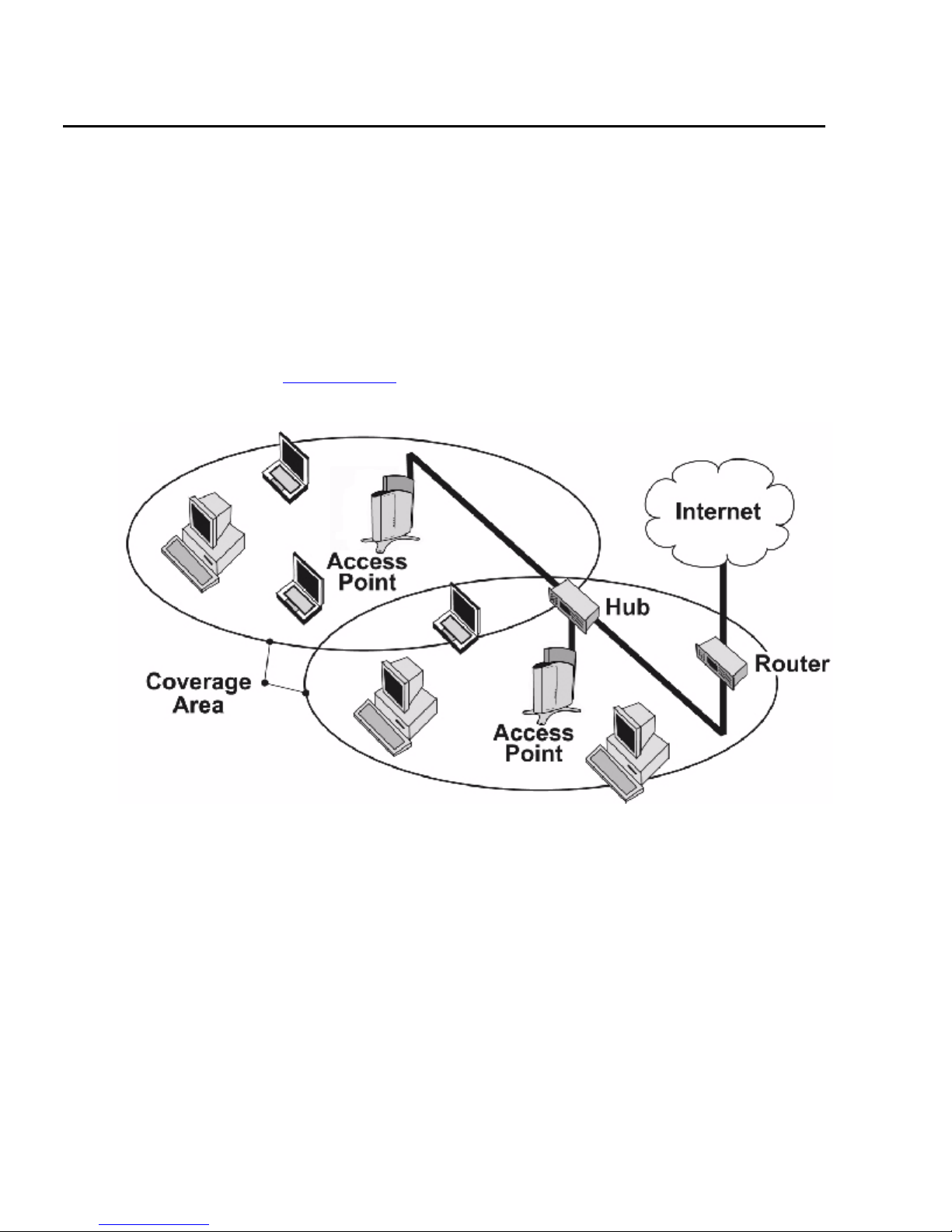
Introduction to Wireless Networking
An AP extends the capability of an existing Ethernet network to devices on a wireless network.
Wireless devices can connect to a single Access Point, or they can move between multiple
Access Points located within the same vicinity. As wireless clients move from one coverage cell
to another, they maintain network connectivity.
To determine the best location for an Access Point, Avaya recommends conducting a Site
Survey before placing the device in its final location. For information about how to conduct a
Site Survey, contact your local reseller.
Before an Access Point can be configured for your specific networking requirements, it must
first be initialized. See Getting Started
Figure 1: Typical wireless network access infrastructure
for details.
Once initialized, the network administrator can configure each unit according to the network’s
requirements. The AP functions as a wireless network access point to data networks. An AP
network provides:
• Seamless client roaming (not available with 802.1x security)
• Easy installation and operation
• Over-the-air encryption of data
• High speed network links
12 Avaya Wireless AP-7 User Guide

Guidelines for Roaming
• An AP can only communicate with client devices that support its wireless standard.
• All Access Points must have the same Network Name to support client roaming.
• All workstations with an 802.11 client adapter installed must use either a Network Name of
“any” or the same Network Name as the Access Points that they will roam between. If an
AP has Closed System enabled, a client must have the same Network Name as the
Access Point to communicate (see Interfaces Tab
• All Access Points and clients must have matching security settings to communicate.
• The Access Points’ cells should overlap to ensure that there are no gaps in coverage and
to ensure that the roaming client will always have a connection available.
• The coverage area of the 802.11b/g radio is larger than the coverage area of the 802.11a
radio. The 802.11b/g radio operates in the 2.4 GHz frequency band; the 802.11a radio
operates in the 5 GHz band. Products that operate in the 2.4 GHz band offer greater range
than products that operate in the 5 GHz band.
• An 802.11a or 802.11b/g AP operates at faster data rates than the 802.11b AP. 802.11a
and 802.11g products operate at speeds of up to 54 Mbits/sec; 802.11b products operate
at speeds of up to 11 Mbits/sec.
IEEE 802.11 Specifications
).
• All Access Points in the same vicinity should use a unique, independent Channel. By
default, the AP automatically scans for available Channels during boot-up but you can also
set the Channel manually (see Interfaces Tab
• Access Points that use the same Channel should be installed as far away from each other
as possible to reduce potential interference.
IEEE 802.11 Specifications
In 1997, the Institute of Electrical and Electronics Engineers (IEEE) adopted the 802.11
standard for wireless devices operating in the 2.4 GHz frequency band. This standard includes
provisions for three radio technologies: direct sequence spread spectrum, frequency hopping
spread spectrum, and infrared. Devices that comply with the 802.11 standard operate at a data
rate of either 1 or 2 Megabits per second (Mbits/sec).
In 1999, the IEEE modified the 802.11 standard to support direct sequence devices that can
operate at speeds of up to 11 Mbits/sec. The IEEE ratified this standard as 802.11b. 802.11b
devices are backwards compatible with 2.4 GHz 802.11 direct sequence devices (that operate
at 1 or 2 Mbits/sec). Available Frequency Channels vary by regulatory domain and/or country.
See 802.11b Channel Frequencies
for details.
for details).
Issue 1 September 2004 13

Introduction
Also in 1999, the IEEE modified the 802.11 standard to support devices operating in the 5 GHz
frequency band. This standard is referred to as 802.11a. 802.11a devices are not compatible
with 2.4 GHz 802.11 or 802.11b devices. 802.11a radios use a radio technology called
Orthogonal Frequency Division Multiplexing (OFDM) to achieve data rates of up to 54 Mbits/
sec. Available Frequency Channels vary by regulatory domain and/or country. See 802.11a
Channel Frequencies for details.
In 2003, the IEEE introduced the 802.11g standard. 802.11g devices operate in the 2.4 GHz
frequency band using OFDM to achieve data rates of up to 54 Mbits/sec. In addition, 802.11g
devices are backwards compatible with 802.11b devices. Available Frequency Channels vary
by regulatory domain and/or country. See 802.11g Channel Frequencies
Management and Monitoring Capabilities
There are several management and monitoring interfaces available to the network administrator
to configure and manage an AP on the network:
• HTTP/HTTPS Interface
for details.
• Command Line Interface
• SNMP Management
HTTP/HTTPS Interface
The HTTP Interface (Web browser Interface) provides easy access to configuration settings
and network statistics from any computer on the network. You can access the HTTP Interface
over your LAN (switch, hub, etc.), over the Internet, or with a “crossover” Ethernet cable
connected directly to your computer’s Ethernet Port.
HTTPS provides an HTTP connection over a Secure Socket Layer. HTTPS is one of two
available secure management options on the AP; the other secure management option is
SNMPv3. Enabling HTTPS allows the user to access the AP in a secure fashion using Secure
Socket Layer (SSL) over port 443. The AP supports SSLv3 with a 128-bit encryption certificate
maintained by the AP for secure communications between the AP and the HTTP client. All
communications are encrypted using the server and the client-side certificate.
The AP comes pre-installed with all required SSL files: default certificate, private key and SSL
Certificate Passphrase installed.
14 Avaya Wireless AP-7 User Guide

Command Line Interface
The Command Line Interface (CLI) is a text-based configuration utility that supports a set of
keyboard commands and parameters to configure and manage an AP.
Users enter Command Statements, composed of CLI Commands and their associated
parameters. Statements may be issued from the keyboard for real time control, or from scripts
that automate configuration.
For example, when downloading a file, administrators enter the download CLI Command along
with IP Address, file name, and file type parameters.
You access the CLI over a HyperTerminal serial connection or via Telnet. During initial
configuration, you can use the CLI over a serial port connection to configure an Access Point’s
IP address. When accessing the CLI via Telnet, you can communicate with the Access Point
from over your LAN (switch, hub, etc.), from over the Internet, or with a “crossover” Ethernet
cable connected directly to your computer’s Ethernet Port.
Management and Monitoring Capabilities
See Using the Command Line Interface (CLI)
CLI commands and parameters.
SNMP Management
In addition to the HTTP and the CLI interfaces, you can also manage and configure an AP using
the Simple Network Management Protocol (SNMP). Note that this requires an SNMP manager
program, like HP Openview or Castlerock’s SNMPc.
The AP supports several Management Information Base (MIB) files that describe the
parameters that can be viewed and/or configured over SNMP:
• MIB-II (RFC 1213)
• Bridge MIB (RFC 1493)
• Ethernet-like MIB (RFC 1643)
• 802.11 MIB
• Avaya Wireless Enterprise MIB
Avaya provides these MIB files on the CD included with each Access Point. You need to
compile one or more of the above MIBs into your SNMP program’s database before you can
manage an Access Point using SNMP. See the documentation that came with your SNMP
manager for instructions on how to compile MIBs.
for more information on the CLI and for a list of
The Enterprise MIB defines the read and read-write objects that can be viewed or configured
using SNMP. These objects correspond to most of the settings and statistics that are available
with the other management interfaces. See the Enterprise MIB for more information; the MIB
can be opened with any text editor, such as Microsoft Word, Notepad, or WordPad.
Issue 1 September 2004 15

Introduction
SNMPv3 Secure Management
SNMPv3 is one of two available secure management options on the AP; the other secure
management option is HTTPS (HTTP connection over Secure Socket Layer). SNMPv3 is based
on the existing SNMP framework, but addresses security requirements for device and network
management.
The security threats addressed by Secure Management are:
• Modification of information: An entity could alter an in-transit message generated by an
authorized entity in such a way as to effect unauthorized management operations,
including the setting of object values. The essence of this threat is that an unauthorized
entity could change any management parameter, including those related to configuration,
operations, and accounting
• Masquerade: Management operations that are not authorized for some entity may be
attempted by that entity by assuming the identity of an authorized entity.
• Message stream modification: SNMP is designed to operate over a connectionless
transport protocol. There is a threat that SNMP messages could be reordered, delayed, or
replayed (duplicated) to effect unauthorized management operations. For example, a
message to reboot a device could be copied and replayed later.
• Disclosure: An entity could observe exchanges between a manager and an agent and
thereby could learn of notifiable events and the values of managed objects. For example,
the observation of a set command that changes passwords would enable an attacker to
learn the new passwords.
To address the security threats listed above, SNMPv3 provides the following when secure
management is enabled:
• Authentication: Provides data integrity and data origin authentication.
• Privacy (also called Encryption): Protects against disclosure of message payload.
• Access Control: Controls and authorizes access to managed objects
The default SNMPv3 username is administrator, with SHA authentication, and DES privacy
protocol.
Note:
Note: The remainder of this guide describes how to configure an AP using the HTTP
Web interface or the CLI interface. For information on how to manage devices
using SNMP, see the documentation that came with your SNMP program. Also,
see the MIB files for information on the parameters available via SNMP.
16 Avaya Wireless AP-7 User Guide

Chapter 2: Getting Started
Chapter Contents
Hardware Description on page 17
•
Prerequisites on page 19
•
Product Package on page 20
•
System Requirements on page 21
•
Hardware Installation on page 21
•
Initialization on page 28
•
Downloading the Latest Software on page 38
•
Additional Hardware Features on page 40
•
Related Topics on page 42
•
Hardware Description
The AP-7 is a tri-mode AP that supports 802.11b, 802.11g, and 802.11a clients. The AP-7
contains one embedded radio: an 802.11a/b/g radio that supports the following operational
modes:
802.11b only mode
•
802.11g only mode
•
802.11bg mode
•
802.11a only mode
•
The AP-7 can be powered through either Active Ethernet (802.3af Power over Ethernet) or
through an external DC power source using the power cord.
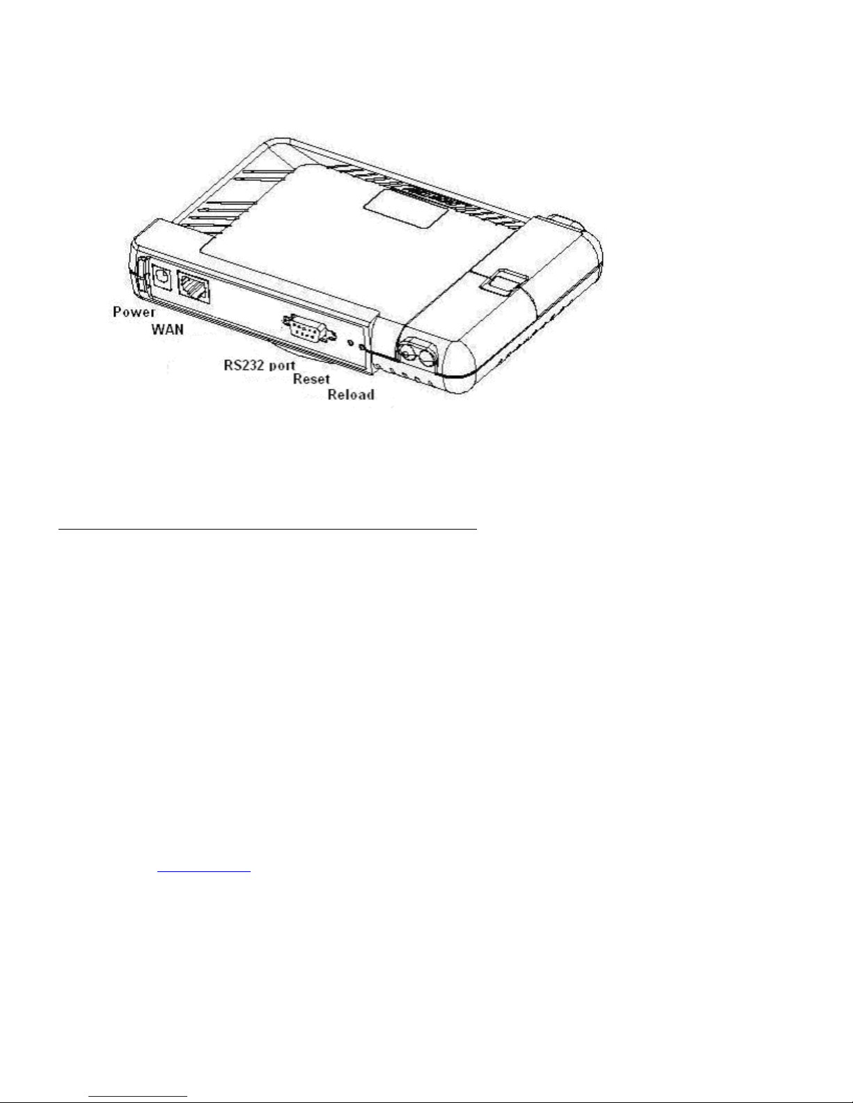
The AP-7 includes a a power jack, a 10/100 base-T Ethernet port, and an RS-232 serial data
communication port (Figure 2-1). The AP-8 includes an optional security cover that can be
installed to protect against access to the power and WAN cables and to the reset and reload
buttons.
Issue 1 September 2004 17
Getting Started
Figure 2: AP-7 Rear Panel
The AP-7 has been designed to rest horizontally on a flat surface, but can be wall or ceiling
mounted with the long axis vertical. The bottom of the unit includes screw slots in the bottom
plastic for mounting to a flat wall or ceiling.
Dual Band Range Extender Antenna Description
The AP-7 can use internal or external antennas. The AP-7 has two diversity antennas
embedded. The internal antennas are arranged to provide both spatial and polarization
diversity. The AP-7 also has two external antenna connectors for use with the Dual Band Range
Extender Antenna (Dual REA).
The Dual Band REA is a dual band indoor antenna that works with both 2.4 GHz (802.11b/g)
and 5 GHz (802.11a) radios. The Dual Band REA can be used with either radio on the AP-8, or
with the AP-7 or AP-6. The Dual Band REA allows for better antenna placement for optimizing
cell size.
Antenna Diversity Options
With one Dual Band REA connected to one of the two antenna connectors on the radio, the AP
supports antenna diversity (one embedded antenna and one external REA) and one of the two
embedded antennas is disabled.
See the Specifications
chapter for more information on the REA.
18 Avaya Wireless AP-7 User Guide

Prerequisites
Before installing an AP-7, you need to gather certain network information. Tab le 1 identifies the
information you need.
Table 1: Required Network Information
Network Information Explanation
Prerequisites
Network Name (SSID of
the wireless cards)
AP’s IP Address If you do not have a DHCP server on your network, then you
HTTP Password Each Access Point requires a read/write password to access the
CLI Password Each Access Point requires a read/write password to access the
SNMP Read Password Each Access Point requires a password to allow get requests
SNMP Read-Write
Password
SNMPv3 Authentication
Password
You must assign the Access Point a Network Name before
wireless users can communicate with it. The clients also need
the same Network Name. This is not the same as the System
Name, which applies only to the Access Point. The network
administrator typically provides the Network Name.
need to assign the Access Point an IP address that is valid on
your network.
web interface. The default password is “public”.
CLI interface. The default password is “public”.
from an SNMP manager. The default password is “public”.
Each Access Point requires a password to allow get and set
requests from an SNMP manager. The default password is
“public”.
If Secure Management is enabled, each Access Point requires a
password for sending authenticated SNMPv3 messages. The
default password is “public”. The default SNMPv3 username is
administrator, with SHA authentication, and DES privacy
protocol.
SNMPv3 Privacy
Password
Security Settings You need to determine what security features you will enable on
Authentication Method A primary authentication server may be configured; a backup
If Secure Management is enabled, each Access Point requires a
password when sending encrypted SNMPv3 data. The default
password is “public”.
the Access Point.
authentication server is optional. The network administrator
typically provides this information.
1 of 2
Issue 1 September 2004 19

Getting Started
Table 1: Required Network Information
Network Information Explanation
Authentication Server
Shared Secret
Authentication Server
Authentication Port
Client IP Address Pool
Allocation Scheme
DNS Server IP Address The network administrator typically provides this IP Address.
Gateway IP Address and
Subnet Mask
Product Package
Each AP comes with the following:
This is a password shared between the Access Point and the
RADIUS authentication server (so both passwords must be the
same), and is typically provided by the network administrator.
This is a port number (default is 1812) and is typically provided
by the network administrator.
The Access Point can automatically provide IP addresses to
clients as they sign on. The network administrator typically
provides the IP Pool range.
The gateway IP address and subnet mask of the network
environment where the Access Point is deployed.
2 of 2
AP-7 unit (with integrated 802.11a/b/g radio, and Active Ethernet)
•
Power adapter
•
One ceiling or wall mounting plate
•
Security cover
•
One Installation CD-ROM that contains the following:
•
- Software Installation Wizard
- ScanTool
- Solarwinds TFTP software
-MIBs
- HTML Help
- this user’s guide in PDF format
One Access Point Quick Start Flyer
•
If any of these items are missing or damaged, please contact your reseller or Technical Support
(see Technical Support for contact information).
20 Avaya Wireless AP-7 User Guide

System Requirements
To begin using an AP, you must have the following minimum requirements:
A 10Base-T Ethernet or 100Base-TX Fast Ethernet switch or hub or cross-over Ethernet
•
cable
At least one of the following IEEE 802.11-compliant devices: An 802.11a, 802.11b, or
•
802.11b/g client device
A computer that is connected to the same IP network as the AP and has one of the
•
following Web browsers installed:
- Microsoft Internet Explorer 6 with Service Pack 1 or later and patch Q323308
- Netscape 6.1 or later
(The computer is required to configure the AP using the HTTP interface.)
System Requirements
Hardware Installation
Unpack the Access Point and accessories from the shipping box. Verify the contents as follows:
AP-7 unit
•
Mounting bracket with screws
•
Power adapter
•
Security cover
•
Quick Installation Flyer
•
Software CD
•
Perform the following procedures to install the AP-7 hardware:
Cabling the AP on page 22
•
Installing the Security Cover on page 23
•
Mounting the AP on page 23
•
Installing Range Extender Antennas on page 25
•
Issue 1 September 2004 21
Getting Started
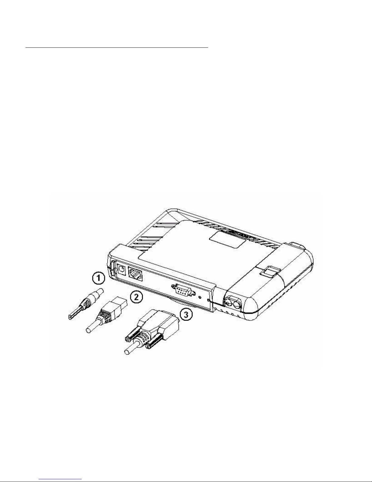
Cabling the AP
Connect cables to the AP-7 as follows:
1. Plug the power cord into the power jack (the left port) and connect the unit to an AC power
outlet (100~240V, 50~60Hz).
2. If using active Ethernet, connect power to the unit from a DC injector device, such as the
Avaya 1-Port Active Ethernet DC Injector hub.
3. Attach one end of an Ethernet cable to the AP's WAN port (the center port, labeled “WAN”)
and the other end to a network hub or switch.
4. Optionally, connect an RS-232 cable to the RS-232 console port (the right port, labeled
“RS-232”).
Note:
Note: You cannot install the security cover to the AP if an RS-232 cable is connected.
Figure 3: Cabling the AP-7
5. Verify LED Status
6. When the AP boots, it performs a series of self-tests.
7. Wait for the power LED to turn green before proceeding.
22 Avaya Wireless AP-7 User Guide

Installing the Security Cover
You can optionally install a security cover to deter unauthorized access to the AP-7. The
security cover is a plastic cover that prevents access to the cabling and to the Reset and Reload
buttons.
Note:
Note: You cannot connect an RS-232 cable to the AP-7 when a security cover is
installed.
1. Slide the hinging end of the security cover into the hole on the rear panel of the AP to the
left of the connectors.
2. Use two screws to screw the right side of the security cover to the RS-232 screw holes on
the rear panel of the AP.
Mounting the AP
Hardware Installation
Conduct a site survey to determine the best location for your device. Once you have chosen a
final location for your unit, mount the AP to a wall or a T-bar ceiling as follows:
Mounting the AP to the Ceiling
•
Mounting the AP to a Wall
•
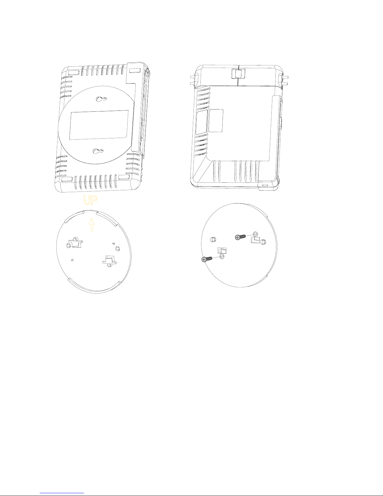
Mounting the AP to the Ceiling
To mount the AP to the ceiling:
1. Attach the mounting plate to the bottom of the AP by lining up the keyholes and attaching it
with two screws.
2. Snap the tabs onto the ceiling T-bar. Rotate the AP until it snaps on to the T-bar.
Issue 1 September 2004 23
Getting Started
Figure 4: AP-7 Mounting Plate
BACK
Mounting the AP to a Wall
To mount the AP to a wall:
1. Put the mounting plate up to the wall.
2. Screw through the mounting plate.
3. Place the AP up against the mounting plate. Orient the AP with the long access vertical,
with the connectors facing to the left.
24 Avaya Wireless AP-7 User Guide
FRONT

Installing Range Extender Antennas
The Dual Band REA is a dual band indoor antenna that works with both 2.4 GHz (802.11b/g)
and 5 GHz (802.11a) radios. You can optionally install one or two Dual Band Range Extender
Antennas (Figure 2-4) on the AP-7.
Figure 5: Dual Band Range Extender Antenna
Antenna Body
Base TopBase Top
Main BaseMain Base
Hardware Installation
Metal PlateMetal Plate
Bottom Plate
Screw Cavity
Perform the following procedures to mount the Dual Band REA to a wall or ceiling and to install
it on the AP:
Wall Mount Installation on page 26
•
Normal Ceiling Installation on page 26
•
T-Bar Ceiling Installation on page 26
•
Attaching Antennas to the AP on page 26
•
Issue 1 September 2004 25

Getting Started
Wall Mount Installation
Perform the following steps to wall mount the Dual Band REA:
1. Detach the Antenna Body from the Main Base.
2. Press the Base Top upward to release it from the Main Base.
3. Use a metal plate or a coin to push the tenon between the Antenna body and the Base Top
to remove the Base Top.
4. Screw the Base Top to the wall.
5. Attach the Antenna Body to the Base Top.
Normal Ceiling Installation
Perform the following step to mount the Dual Band REA to a normal ceiling:
Screw the antenna directly to the ceiling through the hole on the Base; use the anchor if
necessary.
T-Bar Ceiling Installation
Perform the following steps to mount the Dual Band REA to a T-bar ceiling:
1. Detach the Antenna Body from the Main Base.
2. Remove the Metal Plate.
3. Turn over the Bottom Plate and reinstall it on the Main Base.
4. Attach the antenna to the T-Bar and adjust/swivel it to lock on the T-Bar.
Attaching Antennas to the AP
Perform the following steps to attach a Dual Band REA to the AP.
1. Press down near the center of the compartment covering and slide open the External
Antenna Access compartment on the AP.
The compartment closer to the LED panel contains the connectors.
Note:
Note: One AP-7 model does not provide external antenna connectors.
26 Avaya Wireless AP-7 User Guide
 Loading...