

Avaya 59100 Quick Install Manual
a. Prepare the rack
• Provide the equivalent of two racks of vertical space for each 59100 in
an EIA or IEC-standard 19-inch (48.2-centimeter) equipment rack.
• Ensure that the equipment rack is stable and securely attached to a
permanent structure.
• Ground the rack to the same grounding electrode used by the power
service in the area. The ground path must be permanent and must not
exceed 1 Ohm of resistance from the rack to the grounding electrode.
AVAYA recommends using a filter or surge suppressor.
b. When you install the switch into a network, ensure to use the
following cables:
•
Category 5E or higher specification cabling must be used for 1
Gbps/1000 Mbps operation.
• RJ-45 and DB-9 console port cables and adaptors are as follows:
Confirm that you have the tools and package contents as follows:
Tools Required:
• Phillips #2 screwdriver
• Console cable to match the console connector on the switch (DB-9 or RJ-45)
• ESD cable (optional)
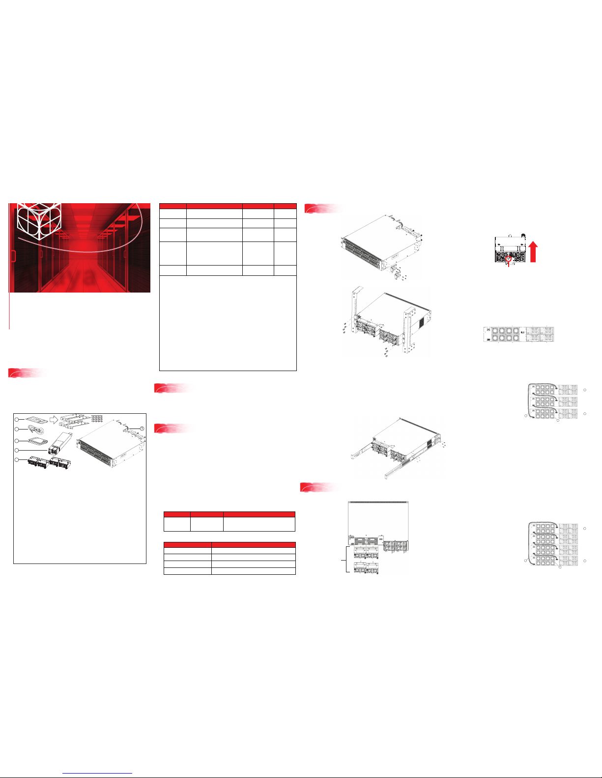
Package Contents:
Ethernet Routing Switch
59100 Series
Quick Install Guide
Avaya
1. Avaya Ethernet Routing Switch 59100 Series.
2. Rack-mounting hardware that includes:
a. Rack-mount brackets
b. Screws to attach brackets to the switch
3. AC power cord.
(Note: A power cord is not included for the A variant of the switch)
4. Documentation includes the Quick Install poster and
Regulatory document.
5. One field replaceable power supply unit.
Note: Four field replaceable power supplies are supported for models
ERS 59100GTS and ERS 59100GTS-PWR+.
6. Four fan tray modules.
Note: Items 5 and 6 do not come with the switch.
These items come in separate package.
1
Before you start
For detailed information about installing the Ethernet Routing Switch 5900
Series switches, see Installing Avaya ERS 5900 Series (NN47211-300).
All documents referenced in this Quick Installation Guide can be
downloaded at www.avaya.com.
Depending on your hardware model, your switch may appear different than
the figures shown in this guide.
Note: Be sure to order Direct Attach cables and SFP or SFP+ Transceivers
if required.
For... Order Order Code
Front-to-Back
cooling
AC Power Supply Front2Back
Cooling (no Power Cord*)
AL7000A0F-E6
AL1905A3F-E6
Quantity
1 to 4**
Back-to-Front
cooling
AC Power Supply Back2Front
Cooling (no Power Cord*)
AL7000A0B-E6
AL1905A3B-E6
1 to 4**
4-post rack
mount bracket
(sold separately)
Four Post Server Rack Mount Kit
(optional) for ERS 59100GTS and
ERS59100GTS-PWR+
AL5911001-E6 1
Console cabling
(sold separately)
Avaya RJ-45/DB-9 Integrated
console cable
Note: 1.8m cable with DB-9
Female for PC and RJ-45 for
device console port
AL2011022-E6 1
Be sure to order Direct Attach cables and SFP or SFP+ Transceivers as required. See
Installing Transceivers and Optical Components on Avaya Ethernet Switch 5900 Series
(NN47211-302) for more information.
* F2B power supply and power cord variants: (non-PWR+)
AL7000B0F-E6 = Europe, AL7000C0F-E6 = UK,
AL7000D0F-E6 = Japan, AL7000E0F-E6 = North America,
AL7000F0F-E6 = Australia/New Zealand
B2F power supply and power cord variants (non-PWR+)
AL7000B0B-E6 = Europe, AL7000C0B-E6 = UK,
AL7000D0B-E6 = Japan, AL7000E0B-E6 = North America,
AL7000F0B-E6 = Australia/New Zealand
* F2B power supply and power cord variants (PWR+):
AL1905B3F-E6 = Europe, AL1905C3F-E6 = UK,
AL1905D4F-E6 = Japan, AL1905E4F-E6 = North America,
AL1905F4F-E6 = Australia/New Zealand
B2F power supply and power cord variants (PWR+)
AL1905B3B-E6 = Europe, AL1905C3B-E6 = UK,
AL1905D4B-E6 = Japan, AL1905E4B-E6 = North America,
AL1905F4B-E6 = Australia/New Zealand
** Avaya recommends four power supplies for redundancy, load
sharing and full hot-swap replacement of a power supply for uninterruptible operation
Chassis without
fans or PSUs
Chassis without PSU, fans, and
power cord
AL590005X-E6
and AL590006X-E6
1
• Unpack the Avaya Ethernet Routing Switch 59100.
• Observe ESD precautions when unpacking.
• The switch ships with a filler panel in the second power supply position. This filler
panel must stay in place if you do not intend to install a second power supply.
2
Unpack equipment
1. Attach a bracket to each
side of the switch.
Install using the optional 4-post rack mount bracket
1. Attach the two sets of front brackets to each guide bracket using sixteen
8.5 mm length flat head machine screws.
2. Attach the guide brackets to the switch chassis.
a. Use four M4 x 5.5 mm low profile undercut flat-head hex machine
screws to attach the rear of each guide bracket to the chassis.
b. Verify if rear screws sit flush in the guide brackets.
c. Test fit the rear mounting brackets in the guide brackets and verify that
the rear brackets can slide in the channels. Remove the rear brackets.
3. Install the switch into the equipment rack temporarily using only the front
rack mounts and screws.
4. Slide a rear mounting bracket into each
guide bracket channel until flush
with the rear rack posts.
a. Slide a rear mounting bracket
into each guide bracket
channel until flush with
the rear rack posts.
b. Secure the rear
mounting brackets
to the switch chassis
with the pan-head screws.
3
PEC Code Name Short Description
AL2011022-E6
Avaya RJ-45/DB-9
CONSOLE CABLE
1.8m cable with DB-9 Female for terminal/PC
on one end and RJ-45 for device console
port connectivity on the other.
PEC Code Description
AA1404037-E6
QSFP+ to QSFP+ 40G 0.5 m (Passive)
AA1404029-E6
QSFP+ to QSFP+ 40G 1 m (Passive)
AA1404031-E6
QSFP+ to QSFP+ 40G 3 m (Passive)
AA1404032-E6
QSFP+ to QSFP+ 40G 5 m (Passive)
c. Stacking cables:
4
Rack mounting
2. Slide the switch into the
rack. Insert and tighten
the rack-mount screws.
For correct switch operation, install both Fan Trays so that the airflow direction
matches the primary Power Supply.
Fan trays can only be inserted in one direction.
• Use the location pin on the Fan Tray to ensure correct orientation in the
chassis. The Fan Tray is upright if the location pin is at the top.
• Once the Fan Tray is installed, tighten the thumbscrews.
Stacking
The Avaya Ethernet Routing Switch 59100 Series provides fail-safe stackability.
You can connect up to four 59100 Series devices in a stack to provide
uninterrupted connectivity for up to 384 ports. You can manage the stack as a
single unit.
The Avaya Ethernet Routing Switch 59100 series back panel provides a Base
Unit switch, Cascade Down connector, and Cascade Up connector for stacking
purposes as shown below:
SDN/Aux Port
Cascade
Down Port
Cascade Up Port
Base Select
Switch
Base Unit Switch – used to designate the base unit in a stack. When set to the
DOWN position, this unit acts as the Base Unit for the stack.
Cascade Down and Cascade Up connectors – used to connect a switch to the
next unit in the stack through a cascade cable. Connect one end of the Cascade
Down cable to the Cascade Up connector of the next switch in the stack (shown
in the simple three-switch stack connection block diagram below):
Simplified Stacking diagram
1 = Base unit
2 = Last unit
3 = 0.5m Cascade/Stack cable
4 = 1.0m Cascade/Stack cable
To create a stack connection, order the appropriate Avaya Ethernet Routing
Switch 59100 Series cascade cables to ensure fail-safe stacking. For stacking
three or more units (maximum stack port count cannot exceed 416 ports, or
4 units), order 0.5 m, 1 m, 3 m or 5 m cables as applicable.
1. Ensure that all switches for the stack are rack mounted.
2. Slide the Unit Select switches on the back of the units to the appropriate
position, depending on whether they are a base unit or non-base unit:
• Base Unit (Unit 1) - Slide the Base Unit switch to the DOWN position.
• Non-Base Unit (Units 2-4) - Slide the Unit Select switch to the UP position.
Because stack parameters are associated with the base unit, the physical
stack order depends on the base unit position and whether you configure
the stack cascade up (stack up) or cascade down (stack down). This
designation depends on the stack cabling arrangement.
NOTE: Avaya recommends you use a Cascade Down (stack down)
configuration.
3. For a Cascade Down configuration, connect stack cables as shown below:
Cascade Down configuration
1 = Base unit
2 = Last unit
3 = 0.5m Cascade/Stack cable
4 = 1.0m Cascade/Stack cable
(Return cable)
Note: Return cable length may
vary depending on unit spacing.
Please ensure proper length
return cable is ordered to
provide adequate strain relief.
Fan Tray
Location pin
Upright
5
Install four Fan Trays in the ERS 59100 switch
Fan Trays
1
2
3
4
Unit 1
Unit 2
Unit 3
5
4
3
2
1
6
1
Unit 4
Unit 1
Unit 2
Unit 3
2
3
4
2
1
Connect the console cable to the ERS 59100
Commissioning the ERS 59100
Property Value
Baud Rate 9600 bps
Data Bits 8
Stop Bits 1
Parity None
Flow Control None
You can install an AC power supply into either power supply slot in
the switch.
The airflow direction of the power supply in PS1 determines the primary airflow
direction for the switch. If PS1 is not present, PS2 determines the airflow
direction. If any power supply location is unpopulated, a PSU Filler Panel must
be installed.
1. Insert the first power supply into the rear PS1 power supply slot. If a
blanking plate covers the required power supply slot, remove the plate
before inserting the power supply. A small angle on the top corner of the
power supply ensures that the power supply can only be installed in one
orientation in the switch.
2. Verify that the power supply is fully seated in the slot and securely clipped in
place.
3. Optional: Install the other power supplies into the rear power supply slots.
The airflow direction must match the primary Power Supply. The switch
ships with a filler panel in PS2, PS3 and PS4 positions. Leave the filler
panel in place if you do not install the other power supplies.
6
Powering Up
Before installing, ensure the switch is up and running, and operating normally. Verify
that the SFP or SFP+ transceivers and network cabling support your network
configuration. Note: The ERS 59100 supports Hot-Swapping of SFP and SFP+
transceivers and direct attach cables.
1. If you are installing SFP direct attach cables, remove packaging, insert the
transceiver connector into a switch port and insert the opposite end into the SFP
port of the corresponding network device.
OR
If you are installing SFP or SFP+ optical transceivers, remove packaging and
insert the pluggable transceiver connector into a switch port.
2. Remove the network interface cover from the transceiver connector
(if applicable) and insert an appropriate network interface cable into
the transceiver.
3. Connect the opposite end of the network interface cable to your network.
4. In both cases, ensure that the device clicks and locks into place.
7
Install SFP and SFP+ transceivers
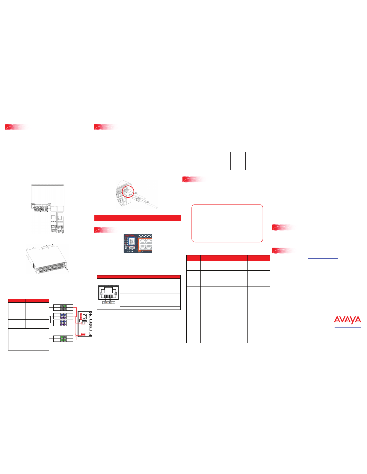
The console port is the RJ-45 port shown with a blue border outline on the
front of your ERS 59100 Series switch (note orientation). Use the console
cable (AL2011022-E6) to connect the switch console port to your management
terminal. The maximum length of a console cable is 25 feet (8.3 meters). The
following table describes the RJ-45 console port pin-out information. You can
use the pin-out information to verify or create a console cable for use with your
maintenance terminal.
Connector Pin Number Signal
1
2
3
4
5
6
7
8
Ready to send (RTS) — optional
Data terminal ready (DTR) — optional,
can swap or link with pin Transmit data
(TXD) — mandatory
Carrier detect (DCD) — optional
Ground (GND) — mandatory
Receive data (RXD) — mandatory
Data set ready (DSR) — optional
Clear to send (CTS) — optional,
can swap or link with pin 1.
The CLI Quickstart welcome screen helps you enter the
information requested at each prompt.
Note: The ERS 59100 uses the default IP address of 192.168.1.1/24 if the switch
does not get its IP address from another source.
Note: the default IP address is not applicable to the out-of-band
management port.
Terminal emulation settings
Warning: You must use a power cord set approved for the 5900 Series switch
and the power receptacle type in your country. Ensure you have properly
grounded the switch before powering up the unit.
The switch will power on immediately when it is connected to a suitable AC
power source. The switch does not have a power switch.
Check the front-panel LEDs as the device powers on to be sure the PWR
LED is lit. If not, check if the power cord is correctly connected.
Check LED status of the fans and power supplies. Status LEDs are on the left
front side of the switch. For more information on all status LEDs, see Installing
Avaya ERS 5900 Series (NN47211-300).
PS3
PS1
Your Setup
All Setups
Status LED (Blinks) Green
until agent software is
loaded, then goes (Solid)
Green
Front to Back Fans
Fan1 – Blue (Solid)
Fan2 – Blue (Solid)
Fan3 – Blue (Solid)
Fan4 – Blue (Solid)
Back to Front Fans
Fan1 – Violet (Solid)
Fan2 – Violet (Solid)
Fan3 – Violet (Solid)
Fan4 – Violet (Solid)
• One Power Supply (PS): One PS LED is solid
Green and three PS LEDs are OFF
• Two PS: Two PS LEDs are solid Green and two
PS LEDs are OFF
• Three PS: Three PS LEDs are solid Green and
one PS LED is OFF
• Four PS: Four PS LEDs are solid Green.
Note: ERS 59100 can work with one power
supply and it can be in any of the four power
supply slots
Base Status
Up Down
PS1 PS2
PS3 PS4
Fan1 Fan2
Fan1 Fan2
Fan3 Fan4
Fan3 Fan4
For more information, go to http://support.avaya.com and download
the following ERS 5900 guides:
• Locating Documentation for ERS 5900 (NN47211-100)
• Documentation Reference for ERS 4900 and ERS 5900 (NN47211-103)
• Installing ERS 5900 (NN47211-300)
• Installation Job Aid for ERS 5900 (NN47211-301)
• Release Notes for ERS 4900 and ERS 5900 (NN47211-400)
1.
Connect the console cable from the terminal to the console port of the
switch to allow initial configuration. Any terminal or PC with the appropriate
terminal emulator can be used as the
management station.
2.
Set the terminal protocol on the terminal or terminal emulation program to
VT100 or VT100/ANSI.
3.
Connect to the switch using the terminal or terminal emulation application.
4.
The Avaya switch banner appears when you connect to the switch through
the Console port. There is no default password for the switch for CLI
console access. Enter Ctrl+Y and type the following CLI commands:
enable
install
Recommended reading
http://support.avaya.com
1-800-242-2121 (U.S.A.)
1-866 GO-AVAYA
1-866-462-8292 (US Sales)
© 2016 Avaya Inc.
Poster part number: 700512658 Rev. 02
NN47211-304, 01.01
###########################################################################
Welcome to the 59100GTS setup utility.
You will be requested to provide the switch basic connectivity settings.
After entering the requested info, the configuration will be applied and
stored into the switch NVRAM.
Once the basic connectivity settings are applied, additional configuration
can be done using the available management interfaces.
Use Ctrl+C to abort the configuration at any time.
###########################################################################
Please provide the Quick Start VLAN <1-4094> [1]:
Please provide the in-band IP Address[192.0.2.1]:
Please provide the in-band sub-net mask[255.255.255.0]:
Please provide the Default Gateway[192.0.2.1]:
Please provide the management sub-net mask[0.0.0.0]:
Please provide the management IP Address[0.0.0.0]:
Please provide the management Default Gateway[0.0.0.0]:
Please provide the Read-Only Community String[**********]:
Please provide the Read-Write Community String[**********]:
Please provide the in-band IPV6 Address/Prefix_length[::/0]:
Please provide the in-band IPV6 Default Gateway[::]:
Please provide the management IPV6 Address/Prefix_length[::/0]:
Please provide the management IPV6 Default Gateway[::]:
###########################################################################
Basic stack parameters have now been configured and saved.
###########################################################################
Avaya Command Line Interface (ACLI)
You can manually load the ACLI script from the console menu or automatically
load the script at startup.
Manual Configuration
You can manually configure the in-band management IP address at any time with
the following ACLI command:
ip address <A.B.C.D> [netmask <A.B.C.D>] [default-gateway <A.B.C.D>]
Example:
1.
Enter Privileged Exec mode:
Switch>enable
2.
Enter the Global Config mode:
#config terminal
3.
Manually configure in-band management IP information:
Switch(config)#ip address 192.0.2.1 netmask 255.255.255.0
default-gateway 192.0.2.0
4.
Verify the information
Switch(config)#show ip
Bootp/DHCP Mode: BootP When Needed
Configured In Use
Last BootP/DHCP
------------- ------------ --------------Stack IP Address: 0.0.0.0 0.0.0.0
Switch IP Address: 192.0.2.1 192.0.2.1 0.0.0.0
Switch Subnet Mask: 255.255.255.0 255.255.255.0 0.0.0.0
Mgmt Stack IP Address: 0.0.0.0
Mgmt Switch IP Address: 0.0.0.0
Mgmt Subnet Mask: 0.0.0.0
Mgmt Def Gateway: 0.0.0.0
Default Gateway: 192.0.2.0 192.0.2.0 0.0.0.0
ACLI boot and factory-default commands:
boot - reboot the switch
boot default - reboot and use the factory default configuration
boot partial-default - reboot and use the partial factory default
configuration
restore factory-default - reset the switch to factory default configuration
Command
Mode
Description Entrance
Commands
User Executive
(Exec mode)
5900>
• Default and Initial access mode
• Requires only Read access
• Used for basic commands
such as show, ping, and logoff
No entrance
command, default
mode
Exit
Commands
exit
or
logout
Privileged EXEC
(PrivExec mode)
5900#
• Used for basic switch level
management tasks; e.g.,
downloading software images,
setting passwords, starting
the switch
• Default and Initial access mode
• Requires only Read access
enable exit
or
logout
Global
Configuration
(Config mode)
5900(config)#
• Used to set and display general
switch parameters such as IP
address, ANMP parameters,
Telnet access and VLANs
• Requires Read-Write access
From Privileged
EXEC mode, enter:
configure
exit
or
logout
Interface
Configuration
(ifconfig mode)
5900(config-if)#
• Used to configure parameters
for each port or VLAN such as
speed, duplex mode, and
rate limiting
• Requires Read-Write access
From Global
Configuration mode, to
configure a port, enter:
interface ethernet
<port_number>
To configure a VLAN,
enter:
interface vlan
<vlan_number>
To configure a
loopback, enter:
interface loopback
<loopback number>.
To configure a
management, enter:
interface mgmt
<mgmt number>
To return to Global
Configuration mode, enter:
exit
To return to Privileged
EXEC mode, enter:
end
To exit ACLI completely,
enter:
logout
Note: Avaya provides two console cable options to connect the ERS 5900’s
DB9 (m) to a standard Pc/Laptop DB9 (m).
1.
A 1.5 m integrated RJ45/DB9 (f) Console Cable (AL2011022-E6) in
conjunction with a DB9(f)/RJ45 Adapter (AL2011020-E6)
OR
2.
Two DB9(f)/RJ45 Adapter (AL2011020-E6) connected together using a
standard Cat5e Ethernet Cable (purchased separately)
For more information on additional modes, see Using ACLI and EDM on Avaya
ERS 4900 and 5900 Series (NN47211-104)
• The micro-USB port on the front panel of the ERS 59100 is not enabled
• The SDN/AUX port on the rear panel of the ERS 59100 is not enabled
General notes
PS4
PS2
 Loading...