

Page 1

Avaya™ Call Management System (CMS)
Sun® Ultra™ 5 Computer
Hardware Installation, Maintenance, and
Troubleshooting
585-215-871
February 2003
Compas ID 79853
Issue 3.3
Page 2

© 2003 Avaya Inc.
All Rights Reserved.
Notice
Every effort was made to ensure that the information in this document
was complete and accurate at the time of printing. However, information
is subject to change.
Preventing Toll Fraud
“Toll fraud” is the unauthorized use of your telecommunications system
by an unaut horized pa rty (for exam ple, a person who is not a corporate
employee, agent, subcontractor, or working on your company's behalf).
Be aware that there may be a risk of toll fraud associated with your
system and that, if toll fraud occurs, it can result in substantial additional
charges for your telecommunications services.
Avaya Fraud Intervention
If you suspect that you are being victimized by toll fraud and you need
technical assistance or support, call Technical Service Center Toll Fraud
Intervention Hotline at +1-800-643-2353 for the United States and
Canada. For additional suppo rt telep ho ne num bers, see the Avaya Web
site:
http://www.avaya.com
Select Support, then select Escalation Lists. This Web site includes
telephone numbers for escalation within the United States. For escalation
telephone numbers outside the United States, select Global Escalation
List.
Providing Telecommunications Security
Telecommunications security (of voice, data, and/or video
communications) is the prevention of any type of intrusion to (that is,
either unauthorized or malicio us access to or use of) your company's
telecommunications equ ipm ent by some part y.
Your company's “telecommunications equipment” includes both this
Avaya product and any other voice/data/video equipment that could be
accessed via this Avaya product (that is, “networked equipment”).
An “outside party” is anyone who is not a corporate employee, agent,
subcontractor, or working on your company's behalf. Whereas, a
“malicious party” is anyone (including someone who may be otherwise
authorized) who accesses your telecommunications equipment with
either malicious or mischievous intent.
Such intrusions may be either to/through synchronous (time-multiplexed
and/or circuit-based) or asynchronous (character-, message-, or packetbased) equipment or interfaces for reasons of:
• Utilization (of capabilities special to the accessed equipment)
• Theft (such as, of intellectual property, financial assets, or
toll-facility access)
• Eavesdropping (priv acy invasi ons to humans)
• Mischief (troubling, but apparently innocuous, tampering)
• Harm (such as harmful tampering, data loss or alteration,
regardless of motive or intent)
Be aware that there may be a risk of unauthorized intrusions associated
with your system and/or its networked equipment. Also realize that, if
such an intrusion should occur, it could result in a variety of losses to your
company (including but not limited to, human/data privacy, intellectual
property, material assets, financial resources, labor costs, and/or legal
costs).
Your Responsibility for Your Company’s Telecommunications
Security
The final responsibility for securing both this system and its networked
equipment rests with you - an Avaya customer's system administrator,
your telecommunications peers, and your managers. Base the fulfillment
of your responsibility on acquired knowledge and resources from a
variety of sources including but not limited to:
• Installation documents
• System administration documents
• Security documents
• Hardware-/software-based security tools
• Shared information between you and your peers
• Telecommunications security experts
To prevent intrusions to your telecommunications equipment, you and
your peers should carefully program and configure:
• your Avaya-provided telecommunications systems and their
interfaces
• your Avaya-provided software applications, as well as their
underlying hardware/software platforms and interfaces
• any other equipment networked to your Avaya products.
Trademarks
AUDIX and C entreVu are registered trademarks of Avaya Inc.
Avaya and INTUITY are trademarks of Avaya, Inc.
CentreCOM is a registered trademark of Allied Telesis.
Comsphere is a registered trademark of Paradyne Inc.
Enterprise, Sun, Solaris, SunVTS, and Netwo rk Terminal Server are
trademarks or registered trademarks of Sun Microsystems, Inc.
Micro Annex is a registered trademark of Nortel Networks, Inc.
Paradyne is a trademark of Paradyne Inc.
Phillips is a registered trademark of the Phillips Screw Company.
Sportster and U.S. Robotics are registered trademarks of U.S. Robotics,
Inc.
UNIX is a registered trademark in the United States and other countries,
licensed exclusively through X/Open Company Limited.
All other product names mentioned herein are the trademarks of their
respective owners.
Avaya Support
Avaya provides a telephone number for you to use to report problems or
to ask questions about your contact center. The support telephone
number is 1-800-242-2121 in the United States. For additional support
telephone numbers, see the Avaya Web site:
http://www.avaya.com
Select Support, then select Escalation Lists. This Web site includes
telephone numbers for escalation within the United States. For escalation
telephone numbers outside the United States, select Global Escalation
List.
Acknowledgment
This document was written by the CRM Information Development group.
Page 3

Avaya Call Management System
Sun Ultra 5 Computer
Hardware Installation, Maintenance, and Troubleshooting
Contents
Contents 3
Preface . . . . . . . . . . . . . . . . . . . . . . . . . . . . . . . . . . . . . . . . 9
Overview . . . . . . . . . . . . . . . . . . . . . . . . . . . . . . . . . . . . . . . 9
Reasons for reissue . . . . . . . . . . . . . . . . . . . . . . . . . . . . . . . . . . 9
Organization . . . . . . . . . . . . . . . . . . . . . . . . . . . . . . . . . . . . . . 11
Related documents. . . . . . . . . . . . . . . . . . . . . . . . . . . . . . . . . . . 12
CMS software documents . . . . . . . . . . . . . . . . . . . . . . . . . . . . . . . 12
Upgrade documents. . . . . . . . . . . . . . . . . . . . . . . . . . . . . . . . . . 13
Hardware documents . . . . . . . . . . . . . . . . . . . . . . . . . . . . . . . . . 15
Switch documents. . . . . . . . . . . . . . . . . . . . . . . . . . . . . . . . . . . 15
Administration docum ents . . . . . . . . . . . . . . . . . . . . . . . . . . . . . . . 16
Other documents . . . . . . . . . . . . . . . . . . . . . . . . . . . . . . . . . . . 16
Documentation Web sites. . . . . . . . . . . . . . . . . . . . . . . . . . . . . . . . 17
Introduction . . . . . . . . . . . . . . . . . . . . . . . . . . . . . . . . . . . . . . . . 19
Overview . . . . . . . . . . . . . . . . . . . . . . . . . . . . . . . . . . . . . . . 19
Support . . . . . . . . . . . . . . . . . . . . . . . . . . . . . . . . . . . . . . . . 20
Frequently asked questions (FAQs) . . . . . . . . . . . . . . . . . . . . . . . . . . 20
Customer support for the United States. . . . . . . . . . . . . . . . . . . . . . . . . 20
Technician support for the United States . . . . . . . . . . . . . . . . . . . . . . . . 20
Customer and technician support outside the United States . . . . . . . . . . . . . . . 20
Installation . . . . . . . . . . . . . . . . . . . . . . . . . . . . . . . . . . . . . . . . 21
Overview . . . . . . . . . . . . . . . . . . . . . . . . . . . . . . . . . . . . . . . 21
Preparing for installation . . . . . . . . . . . . . . . . . . . . . . . . . . . . . . . . 22
Safety precautions . . . . . . . . . . . . . . . . . . . . . . . . . . . . . . . . . . 22
System precautions . . . . . . . . . . . . . . . . . . . . . . . . . . . . . . . . . . 23
Require d tools . . . . . . . . . . . . . . . . . . . . . . . . . . . . . . . . . . . . 23
Electrical specifications . . . . . . . . . . . . . . . . . . . . . . . . . . . . . . . . 24
Physical specifications . . . . . . . . . . . . . . . . . . . . . . . . . . . . . . . . 25
Environmental specifications. . . . . . . . . . . . . . . . . . . . . . . . . . . . . . 25
Miscellaneous sp ec ifi ca tio ns. . . . . . . . . . . . . . . . . . . . . . . . . . . . . . 26
Unpacking and inventorying the equipment . . . . . . . . . . . . . . . . . . . . . . . 27
Parts list . . . . . . . . . . . . . . . . . . . . . . . . . . . . . . . . . . . . . . . 28
Determining the computer model. . . . . . . . . . . . . . . . . . . . . . . . . . . . 29
Features . . . . . . . . . . . . . . . . . . . . . . . . . . . . . . . . . . . . . . 29
Physical labeling . . . . . . . . . . . . . . . . . . . . . . . . . . . . . . . . . . 30
Issue 3.3 February 2003 3
Page 4

Contents
Setting up power . . . . . . . . . . . . . . . . . . . . . . . . . . . . . . . . . . . . 33
Peripheral connectivity . . . . . . . . . . . . . . . . . . . . . . . . . . . . . . . . . 34
Parts list . . . . . . . . . . . . . . . . . . . . . . . . . . . . . . . . . . . . . . . . 36
Connecting the monitor and keyboard . . . . . . . . . . . . . . . . . . . . . . . . . . 37
Connecting the remote console modem . . . . . . . . . . . . . . . . . . . . . . . . . 38
Connecting to external interfaces . . . . . . . . . . . . . . . . . . . . . . . . . . . . 39
Turning the system on and verifying POST . . . . . . . . . . . . . . . . . . . . . . . 46
Identifying installed PCI cards. . . . . . . . . . . . . . . . . . . . . . . . . . . . . . 49
Setting the remote console modem options . . . . . . . . . . . . . . . . . . . . . . . 50
Turning the system over for provisioning. . . . . . . . . . . . . . . . . . . . . . . . . 57
Software check. . . . . . . . . . . . . . . . . . . . . . . . . . . . . . . . . . . 30
Computer layout . . . . . . . . . . . . . . . . . . . . . . . . . . . . . . . . . . . 31
Front Panel . . . . . . . . . . . . . . . . . . . . . . . . . . . . . . . . . . . . 31
Rear Panel (with SunSwift® card). . . . . . . . . . . . . . . . . . . . . . . . . . 31
Rear Panel (with UltraSCSI card) . . . . . . . . . . . . . . . . . . . . . . . . . . 32
Connecting the switch link . . . . . . . . . . . . . . . . . . . . . . . . . . . . . . . 39
Connecting the serial port expander box . . . . . . . . . . . . . . . . . . . . . . . . 40
Connecting external SCSI devices. . . . . . . . . . . . . . . . . . . . . . . . . . . 41
SunSwift connections. . . . . . . . . . . . . . . . . . . . . . . . . . . . . . . . 41
UltraSCSI connections . . . . . . . . . . . . . . . . . . . . . . . . . . . . . . . 43
Sportster 33.6 faxmodem . . . . . . . . . . . . . . . . . . . . . . . . . . . . . . . 50
Paradyne Comsphere 3910 modem . . . . . . . . . . . . . . . . . . . . . . . . . . 52
Recommended options . . . . . . . . . . . . . . . . . . . . . . . . . . . . . . . 52
Option buttons . . . . . . . . . . . . . . . . . . . . . . . . . . . . . . . . . . . 52
Setting the options . . . . . . . . . . . . . . . . . . . . . . . . . . . . . . . . . 53
Maintenance . . . . . . . . . . . . . . . . . . . . . . . . . . . . . . . . . . . . . . . . 59
Overview . . . . . . . . . . . . . . . . . . . . . . . . . . . . . . . . . . . . . . . 59
Computer layout . . . . . . . . . . . . . . . . . . . . . . . . . . . . . . . . . . . . 60
Front Panel. . . . . . . . . . . . . . . . . . . . . . . . . . . . . . . . . . . . . . 60
Rear Panel (with SunSwift card) . . . . . . . . . . . . . . . . . . . . . . . . . . . . 61
Rear Panel (with UltraSCSI card) . . . . . . . . . . . . . . . . . . . . . . . . . . . 62
ESD precautions . . . . . . . . . . . . . . . . . . . . . . . . . . . . . . . . . . . . 63
Maintaining PCI cards . . . . . . . . . . . . . . . . . . . . . . . . . . . . . . . . . 64
Overview. . . . . . . . . . . . . . . . . . . . . . . . . . . . . . . . . . . . . . . 64
Require d references . . . . . . . . . . . . . . . . . . . . . . . . . . . . . . . . . 64
Identifying free card slots . . . . . . . . . . . . . . . . . . . . . . . . . . . . . . . 64
PCI card configuration. . . . . . . . . . . . . . . . . . . . . . . . . . . . . . . . . 65
Installing or removing PCI cards . . . . . . . . . . . . . . . . . . . . . . . . . . . . 66
Replacing an UltraSCSI card with a SunSwift card . . . . . . . . . . . . . . . . . . . 68
Prerequisites. . . . . . . . . . . . . . . . . . . . . . . . . . . . . . . . . . . . 68
Procedure . . . . . . . . . . . . . . . . . . . . . . . . . . . . . . . . . . . . . 68
SAI/P cards. . . . . . . . . . . . . . . . . . . . . . . . . . . . . . . . . . . . . . 71
Identifying device entry names for ports on an SAI/P card . . . . . . . . . . . . . . 71
Adding, moving, or removing an SAI/P card . . . . . . . . . . . . . . . . . . . . . 71
Removing SAI/P drivers and utilities. . . . . . . . . . . . . . . . . . . . . . . . . 75
Installing HSI/P cards . . . . . . . . . . . . . . . . . . . . . . . . . . . . . . . . . 77
4 Avaya CMS Sun Ultra 5 Computer Hardware Installation, Maintenance, and Troubleshooting
Page 5

Replacing an HSI/P card . . . . . . . . . . . . . . . . . . . . . . . . . . . . . . 78
Installing the first HSI/P card or a pair of HSI/P cards . . . . . . . . . . . . . . . . . 78
Installing HSI/P software and patches . . . . . . . . . . . . . . . . . . . . . . . . 79
Setting up the switch link for each ACD . . . . . . . . . . . . . . . . . . . . . . . 80
Adding a second HSI/P card . . . . . . . . . . . . . . . . . . . . . . . . . . . . 81
Maintaining disk drives . . . . . . . . . . . . . . . . . . . . . . . . . . . . . . . . . 83
Overview . . . . . . . . . . . . . . . . . . . . . . . . . . . . . . . . . . . . . . . 83
Disk drive compatibility with CMS loads . . . . . . . . . . . . . . . . . . . . . . . . 83
Prerequisites . . . . . . . . . . . . . . . . . . . . . . . . . . . . . . . . . . . . . 83
Require d references . . . . . . . . . . . . . . . . . . . . . . . . . . . . . . . . . 84
Replacing the primary internal EIDE boot disk drive . . . . . . . . . . . . . . . . . . . 85
Opening the computer . . . . . . . . . . . . . . . . . . . . . . . . . . . . . . . 85
Removing the primary internal boot disk drive . . . . . . . . . . . . . . . . . . . . 87
Install ing the new primary internal disk drive . . . . . . . . . . . . . . . . . . . . . 89
Closing the computer . . . . . . . . . . . . . . . . . . . . . . . . . . . . . . . . 91
Turning on the system . . . . . . . . . . . . . . . . . . . . . . . . . . . . . . . 92
Adding or replacing the internal EIDE data disk drive . . . . . . . . . . . . . . . . . . 93
Unpacking the disk drive . . . . . . . . . . . . . . . . . . . . . . . . . . . . . . 93
Opening the computer . . . . . . . . . . . . . . . . . . . . . . . . . . . . . . . 94
Removing the secondary internal disk drive . . . . . . . . . . . . . . . . . . . . . 96
Removing the diskette drive. . . . . . . . . . . . . . . . . . . . . . . . . . . . . 97
Installing new cabling . . . . . . . . . . . . . . . . . . . . . . . . . . . . . . . . 98
Installing the secondary disk drive . . . . . . . . . . . . . . . . . . . . . . . . . . 99
Closing the computer . . . . . . . . . . . . . . . . . . . . . . . . . . . . . . . . 100
Turning on the system . . . . . . . . . . . . . . . . . . . . . . . . . . . . . . . 101
Adding or replacing external SCSI disk drives . . . . . . . . . . . . . . . . . . . . . 102
Adding or replacing a disk drive . . . . . . . . . . . . . . . . . . . . . . . . . . . 102
Turning on the system . . . . . . . . . . . . . . . . . . . . . . . . . . . . . . . 108
Setting up the disk drives . . . . . . . . . . . . . . . . . . . . . . . . . . . . . . . 110
Partitioning disk drives . . . . . . . . . . . . . . . . . . . . . . . . . . . . . . . . 111
R3V9 and later . . . . . . . . . . . . . . . . . . . . . . . . . . . . . . . . . . . 111
R3V8 and earlier . . . . . . . . . . . . . . . . . . . . . . . . . . . . . . . . . . 111
Disk partition values . . . . . . . . . . . . . . . . . . . . . . . . . . . . . . . . 111
Partitioning and formattin g a disk . . . . . . . . . . . . . . . . . . . . . . . . . . 117
Administering data disk drives . . . . . . . . . . . . . . . . . . . . . . . . . . . . . 121
Administering new data disks, R3V9 and later . . . . . . . . . . . . . . . . . . . . 121
Administering replacement data disks, R3V9 and later . . . . . . . . . . . . . . . . 122
Administering a new data disk, R3V8 and earlier . . . . . . . . . . . . . . . . . . . 122
Administering a replacement data disk, R3V8 and earlier . . . . . . . . . . . . . . . 126
Replacing the CD-ROM drive . . . . . . . . . . . . . . . . . . . . . . . . . . . . . . 130
Opening the computer. . . . . . . . . . . . . . . . . . . . . . . . . . . . . . . . . 130
Removing and replacing the CD-ROM drive . . . . . . . . . . . . . . . . . . . . . . 132
Closing the computer . . . . . . . . . . . . . . . . . . . . . . . . . . . . . . . . . 133
Turning on the system. . . . . . . . . . . . . . . . . . . . . . . . . . . . . . . . . 134
Maintaining tape drives . . . . . . . . . . . . . . . . . . . . . . . . . . . . . . . . . 135
Overview . . . . . . . . . . . . . . . . . . . . . . . . . . . . . . . . . . . . . . . 135
Require d references . . . . . . . . . . . . . . . . . . . . . . . . . . . . . . . . . 135
Ordering tapes . . . . . . . . . . . . . . . . . . . . . . . . . . . . . . . . . . . . 135
Cleaning the tape drive . . . . . . . . . . . . . . . . . . . . . . . . . . . . . . . . 136
Contents
Issue 3.3 February 2003 5
Page 6

Contents
DDS4 tape drive . . . . . . . . . . . . . . . . . . . . . . . . . . . . . . . . . . 136
SLR5 tape drive . . . . . . . . . . . . . . . . . . . . . . . . . . . . . . . . . . 137
XL/XS/DX tape drive . . . . . . . . . . . . . . . . . . . . . . . . . . . . . . . . 137
Adding, removing, or replacing tape drives . . . . . . . . . . . . . . . . . . . . . . . 138
Adding or replacing a tape drive. . . . . . . . . . . . . . . . . . . . . . . . . . . 138
Removing a tape drive . . . . . . . . . . . . . . . . . . . . . . . . . . . . . . . 145
Adding memory and replacing the CPU . . . . . . . . . . . . . . . . . . . . . . . . . 147
Overview. . . . . . . . . . . . . . . . . . . . . . . . . . . . . . . . . . . . . . . 147
Installing memory . . . . . . . . . . . . . . . . . . . . . . . . . . . . . . . . . . . 147
Checking the current memory size . . . . . . . . . . . . . . . . . . . . . . . . . 147
Opening the computer . . . . . . . . . . . . . . . . . . . . . . . . . . . . . . . 148
Adding the DIMMs . . . . . . . . . . . . . . . . . . . . . . . . . . . . . . . . . 150
Closing the computer . . . . . . . . . . . . . . . . . . . . . . . . . . . . . . . . 151
Checking the new memory size . . . . . . . . . . . . . . . . . . . . . . . . . . . 151
Adding swap space (R3V6 or earlier only) . . . . . . . . . . . . . . . . . . . . . . 152
Troubleshooting . . . . . . . . . . . . . . . . . . . . . . . . . . . . . . . . . . . . . . 153
Overview . . . . . . . . . . . . . . . . . . . . . . . . . . . . . . . . . . . . . . . 153
References . . . . . . . . . . . . . . . . . . . . . . . . . . . . . . . . . . . . . . 153
Using the remote console. . . . . . . . . . . . . . . . . . . . . . . . . . . . . . . . 154
Overview. . . . . . . . . . . . . . . . . . . . . . . . . . . . . . . . . . . . . . . 154
Redirecting the console using Solaris . . . . . . . . . . . . . . . . . . . . . . . . . 154
Redirecting the local console to the remote console . . . . . . . . . . . . . . . . . 154
Redirecting the remote console back to the local console. . . . . . . . . . . . . . . 156
Redirecting the console using OpenBoot mode . . . . . . . . . . . . . . . . . . . . . 157
Redirecting the local console to the remote console . . . . . . . . . . . . . . . . . 157
Redirecting the remote console back to the local console. . . . . . . . . . . . . . . 158
Tools . . . . . . . . . . . . . . . . . . . . . . . . . . . . . . . . . . . . . . . . . 161
Using the prtdiag command . . . . . . . . . . . . . . . . . . . . . . . . . . . . . . 162
System messages . . . . . . . . . . . . . . . . . . . . . . . . . . . . . . . . . . 163
OpenBoot PROM firmware tests . . . . . . . . . . . . . . . . . . . . . . . . . . . . 164
Using the OpenBoot PROM tests . . . . . . . . . . . . . . . . . . . . . . . . . . 164
Test descriptions . . . . . . . . . . . . . . . . . . . . . . . . . . . . . . . . . . 165
Probing IDE devices . . . . . . . . . . . . . . . . . . . . . . . . . . . . . . . . 166
Probing SCSI devices . . . . . . . . . . . . . . . . . . . . . . . . . . . . . . . 167
OpenBoot diagnostic tests. . . . . . . . . . . . . . . . . . . . . . . . . . . . . . . 169
POST diagnostic messages . . . . . . . . . . . . . . . . . . . . . . . . . . . . . . 172
Memory failure . . . . . . . . . . . . . . . . . . . . . . . . . . . . . . . . . . . 172
OpenBoot initialization commands . . . . . . . . . . . . . . . . . . . . . . . . . . . 173
Diagnosing LED patterns . . . . . . . . . . . . . . . . . . . . . . . . . . . . . . . 174
Keyboard LED patterns . . . . . . . . . . . . . . . . . . . . . . . . . . . . . . . 174
Tape drive LED status patterns . . . . . . . . . . . . . . . . . . . . . . . . . . . 174
Sun Validation Test Suite (VTS) . . . . . . . . . . . . . . . . . . . . . . . . . . . . 176
Prerequisites. . . . . . . . . . . . . . . . . . . . . . . . . . . . . . . . . . . . 176
Using SunVTS . . . . . . . . . . . . . . . . . . . . . . . . . . . . . . . . . . . 176
Troubleshooting disk drives and CD-ROM drives. . . . . . . . . . . . . . . . . . . . . 177
Troubleshooting tape drives. . . . . . . . . . . . . . . . . . . . . . . . . . . . . . . 179
Overview. . . . . . . . . . . . . . . . . . . . . . . . . . . . . . . . . . . . . . . 179
6 Avaya CMS Sun Ultra 5 Computer Hardware Installation, Maintenance, and Troubleshooting
Page 7

Checking tape status . . . . . . . . . . . . . . . . . . . . . . . . . . . . . . . . . 179
Rebuilding tape device drivers . . . . . . . . . . . . . . . . . . . . . . . . . . . . . 181
Recovery procedures. . . . . . . . . . . . . . . . . . . . . . . . . . . . . . . . . . 182
Preserving data after a system failure . . . . . . . . . . . . . . . . . . . . . . . . . 182
Loss of power. . . . . . . . . . . . . . . . . . . . . . . . . . . . . . . . . . . . . 182
Keyboard becomes unplugged. . . . . . . . . . . . . . . . . . . . . . . . . . . . . 183
Probe command warnings. . . . . . . . . . . . . . . . . . . . . . . . . . . . . . . 184
Reseating HSI/P cards . . . . . . . . . . . . . . . . . . . . . . . . . . . . . . . . 185
Remote console port problems. . . . . . . . . . . . . . . . . . . . . . . . . . . . . 186
Appendix A: Factory hardware installation . . . . . . . . . . . . . . . . . . . . . . . 189
Overview . . . . . . . . . . . . . . . . . . . . . . . . . . . . . . . . . . . . . . . 189
Preparing for factory hardware installation . . . . . . . . . . . . . . . . . . . . . . . . 190
Computer layout . . . . . . . . . . . . . . . . . . . . . . . . . . . . . . . . . . . 190
Front Panel . . . . . . . . . . . . . . . . . . . . . . . . . . . . . . . . . . . . 190
Rear Panel (with SunSwift card). . . . . . . . . . . . . . . . . . . . . . . . . . . 191
Rear Panel (with UltraSCSI card) . . . . . . . . . . . . . . . . . . . . . . . . . . 191
ESD precautions . . . . . . . . . . . . . . . . . . . . . . . . . . . . . . . . . . . 192
Installing an optional second internal hard drive . . . . . . . . . . . . . . . . . . . . . 193
Unpacking the disk drive . . . . . . . . . . . . . . . . . . . . . . . . . . . . . . 193
Opening the computer . . . . . . . . . . . . . . . . . . . . . . . . . . . . . . . 194
Removing the secondary internal disk drive . . . . . . . . . . . . . . . . . . . . . 196
Removing the diskette drive. . . . . . . . . . . . . . . . . . . . . . . . . . . . . 197
Installing new cabling . . . . . . . . . . . . . . . . . . . . . . . . . . . . . . . . 198
Installing the secondary disk drive . . . . . . . . . . . . . . . . . . . . . . . . . . 199
Closing the computer . . . . . . . . . . . . . . . . . . . . . . . . . . . . . . . . 200
Installing memory. . . . . . . . . . . . . . . . . . . . . . . . . . . . . . . . . . . . 201
Overview. . . . . . . . . . . . . . . . . . . . . . . . . . . . . . . . . . . . . . 201
Opening the computer . . . . . . . . . . . . . . . . . . . . . . . . . . . . . . . 201
Adding the memory modules . . . . . . . . . . . . . . . . . . . . . . . . . . . . 203
Closing the computer . . . . . . . . . . . . . . . . . . . . . . . . . . . . . . . . 204
Installing PCI cards. . . . . . . . . . . . . . . . . . . . . . . . . . . . . . . . . . . 205
PCI card configuration. . . . . . . . . . . . . . . . . . . . . . . . . . . . . . . . . 205
Installing PCI cards . . . . . . . . . . . . . . . . . . . . . . . . . . . . . . . . . . 206
Contents
Glossary . . . . . . . . . . . . . . . . . . . . . . . . . . . . . . . . . . . . . . . . 209
Index . . . . . . . . . . . . . . . . . . . . . . . . . . . . . . . . . . . . . . . . 211
Issue 3.3 February 2003 7
Page 8

Contents
8 Avaya CMS Sun Ultra 5 Computer Hardware Installation, Maintenance, and Troubleshooting
Page 9

Preface
Overview
Avaya™ Call Management System (CMS) Sun® Ultra™ 5 Computer Hardware
Installation, Main tenance, and Troubleshooting, 585-215-871, is written for technicians
who install and maintain call center applications such as Avaya CMS.
Reasons for reissue
Issue 3.3 of this document was issued for the following changes:
● To add partitioning information for the 36-GB external SCSI disk drive (see Partitioning
disk drives on pag e 111).
● To update the tape ordering procedures (see Ordering tapes on page 135).
● To make general word ing and format corrections to the document.
Issue 3.2 of this document was issued for the following changes:
● To update the disk drive maintenance procedures, including new disk partitioning for
CMS R3V11 (see Maintaining disk drives
● To make general word ing and format corrections to the document.
on page 83).
Issue 3.1 of this document was issued for the following changes:
● To add partitioning information for a new 4-GB EIDE disk drive (see Disk partition
values, R3V8 and earlier data disks on page 115).
● To remove information about installing network hubs and Network Terminal Servers
(NTS). This information is now contained in Avaya CMS Terminals, Printers, and
Modems, 585-215-874.
● To remove references to the product name CentreVu
● To make general wording corrections to the document.
®
.
Issue 3.3 February 2003 9
Page 10

Preface
Issue 3.0 of this document was issued for the following changes:
● To update the disk drive maintenance procedures for CMS R3V9 (see Maintaining disk
drives on page 83).
● To add information about the 18-GB external SCSI disk drive (see Disk partition
values on page 1 11).
● To make general wording corrections to the document.
Issue 2.2 of this document was issued for the following changes:
● To change references from Lucent Technologies to Avaya.
● To add information about the 20-GB disk drive (see Overview on page 19, Determining
the computer model on page 29, and Disk partition values on page 111).
● To add information about disk configurations (see Overview on page 19).
● To add information about the 400 MHz CPU (see Determining the computer model on
page 29).
● To add information about the new autosensing power supply (see Setting up power on
page 33).
● To update the HSI card installation procedures (see Installing HSI/P cards on page 77).
● To update the disk drive maintenance procedures (see Maintaining disk drives on
page 83).
● To update the remote console procedure (see Using the remote console on page 154).
● To add information about system messages (see System messages on page 163).
● To add tape drive LED status patterns (see Tape drive LED status patterns on
page 174).
● To remove information about specific UPS models. A UPS is still required, but must be
provided locally.
● To make the organization of this book consistent with other Sun hardware installation
books.
● To make general wording corrections to the document.
Issue 2.1 of this document was issued for the following changes:
● To add information about the new Digital Data S tor age (DDS) model DDS4, 4-milli meter
tape drive. This tape drive replaces the SLR5 Quarter-Inch-Cartridge (QIC) tape drive.
● To move hardware maintenance and troubleshooting inf or mation t o this do cument. This
information was previously found in CentreVu Call Management System R3V8
Hardware Maintenance and Troubleshooting, 585-215-873.
● To make general wording corrections to the document.
10 Avaya CMS Sun Ultra 5 Computer Hardware Installation, Maintenance, and Troubleshooting
Page 11

Organization
This document is organized as follows:
● Introduction – Provides an overview of the Ultra 5 computer and helpline informati on.
● Installation – Describes how to assemble the Ultra 5 computer, connect external
devices, and power-up the computer.
● Maintenance – Describes how to maintain the Ultra 5 computer.
● Troubleshooting – Describes how to troubleshoot the Ultra 5 computer.
● Factory hardware installation – Describes how to config ure the Ultra 5 to factory
specifications.
● Glossary
● Index
Organization
Issue 3.3 February 2003 11
Page 12

Preface
Related documents
Related documents lists sources for information related to contact center products and
features. Not all documents are suppor ted for all CMS releases or equipment.
To order Avaya documentation, call the Avaya Publications Center at 1-800-457-1235
(United S tates and Canada) or +1-207-866-6701 (outside the United States and Canada).
CMS software docu ments
Document title Document
Installing software on a CMS computer
number
Avaya CMS R3V11 Software Installation, Maintenance, and Troubleshooting Guide 585-215-115
CentreVu Call Management System Release 3 Version 9 Software Inst allation,
Maintenance, and Troubleshooting
Setting up a disk-mirrored system
Avaya CMS R3V11 Software Installation, Maintenance, and Troubleshooting Guide 585-215-115
CentreVu Call Management System Release 3 Version 9 Software Inst allation,
Maintenance, and Troubleshooting
585-215-956
585-215-956
12 Avaya CMS Sun Ultra 5 Computer Hardware Installation, Maintenance, and Troubleshooting
Page 13
Related documents
Upgrade docume nts
There are several upgrade paths supported with CMS. There is a document designed to
support each upgrade. Note that none of the following upgrade documents are available
from the publications center.
● Base load upgrades
Use a base load upgrade when upgrading CMS to the latest load of the same version
(for example, R3V9 ak.g to R3V9 al.k). A specific set of instructions is written for the
upgrade and is shipped to the customer site with the CMS sof tware CD-ROM as part of
a Quality Protection Plan Change Notice (QPPCN).
Document title
Avaya CMS R3V11 Base Load Upgrades
CentreVu Call Management System Release 3 Version 9 Base Load Upgrade Procedures
● Platform upgrades and data migration
Use a platform upgrade when upgrading to a new hardware platform (for example,
upgrading from a SPARCserver 5 to an Enterprise 3500). The new hardware platform
is shipped from the factory with the latest CMS load. Therefore, as part of the upgrade
you will have the latest CMS load (for example, R3V9 to R3V11 or the latest load of the
same CMS version). For R3V11, a specific set of i nstruct io ns is wri tten for the u pgrade
and is shipped to the customer site with the new hardware.
Document title
Avaya Call Management System Release 3 Version 11 Platform Upgrade and Data Migration
CentreVu Call Management System Release 3 Version 9 Platform Upgrade and Data Migration
Instructions
Issue 3.3 February 2003 13
Page 14

Preface
● Avaya Call Management System Upgrade Express (CUE)
Use CUE in the following conditions:
— CMS is being upgraded from an earlier version (f or example, R3V5u or R3V6) t o the
latest version (for example, R3V9 or R3V11).
— The hardware platform is not changing.
A specific set of upgrade instructions is written for the upgrade and is shipped to the
customer site with the CUE kit.
Document title
Avaya Call Management System Release 3 Ver sion 1 1 Sun Blade 100 Workstation CMS Upgrade
Express
Avaya Call Management System Release 3 V er sion 11 Sun Blade 100 Workstation Mirrored System
CMS Upgrade Express
Avaya Call Management System Release 3 V er sion 11 Sun Ultra 5 Computer CMS Upgrade Express
Avaya Call Management System Release 3 Version 11 Sun Enterprise 3000 Computer CMS
Upgrade Express
Avaya Call Management System Release 3 Version 11 Sun Enterprise 3000 Computer Mirrored
System CMS Upgrade Express
Avaya Call Management System Release 3 Version 11 Sun Enterprise 3500 Computer CMS
Upgrade Express
Avaya Call Management System Release 3 Version 11 Sun Enterprise 3500 Computer Mirrored
System CMS Upgrade Express
CentreVu Call Management System Release 3 Version 9 Sun Ultra 5 Computer CVUE Instructions
CentreVu Call Management System Release 3 Version 9 Sun Enterprise 3000 Computer CVUE
Instructions
CentreVu Call Management System Release 3 Version 9 Sun Enterprise 3000 Computer Mirrored
System CVUE Instructions
CentreVu Call Management System Release 3 Version 9 Sun Enterprise 3500 Computer CVUE
Instructions
CentreVu Call Management System Release 3 Version 9 Sun Enterprise 3500 Computer Mirrored
System CVUE Instructions
14 Avaya CMS Sun Ultra 5 Computer Hardware Installation, Maintenance, and Troubleshooting
Page 15
Hardware documents
Related documents
Document title Document
number
Avaya Call Management System Sun Fire V880 Computer Hardware Installation,
Maintenance, and Troubleshooting
Avaya Call Management System Sun Fire V880 Computer Connectivity Di agram 585-215-612
Avaya Call Management System Sun Blade 100/150 Computer Hardware
Installation, Maintenance, and Troubleshooting
Call Management System Sun Blade 100/150 Computer Connectivity Diagram 585-310-782
Avaya Call Management System Sun Enterprise 3500 Computer Hardware
Installation, Maintenance, and Troubleshooting
Call Management System Sun Enterprise 3500 Computer Connectivity Diagram 585-215-877
Avaya Call Management System Sun Ultra 5 Computer Hardware Installation,
Maintenance, and Troubleshooting
Call Management System Sun Ultra 5 Computer Connectivity Diagram 585-215-872
Avaya Call Management System Sun Enterprise 3000 and SPARCserver
Computers Hardware Maintenance and Troubleshooting
Avaya Call Management System Terminals, Printers, and Modems 585-215-874
585-215-116
585-310-783
585-215-873
585-215-871
585-214-016
Switch documents
Document title Document
Avaya Call Management System Switch Connections, Admini stration, and
Troubleshooting
number
585-215-876
Issue 3.3 February 2003 15
Page 16
Preface
Administration doc ume nts
Document title Document
number
Avaya Call Management System Release 3 Version 11 Administration 585-215-515
CentreVu Call Management System Release 3 Version 9 Administration 585-214-015
Other documents
Document title Document
number
Avaya CMS Open Database Connectivity 585-780-701
Avaya CMS R3V11 LAN Backup User Guide 585-215-715
Avaya CMS R3V11 External Call History Interface 585-780-700
CentreVu CMS Release 3 Version 9 External Call History Interface 585-215-952
Avaya CMS Custom Reports 585-215-822
Avaya CMS Forecast 585-215-825
Avaya Visual Vectors Version 11 Installation and Getting Started 585-210-706
Avaya Visual Vectors Version 11 User Guide 585-210-709
Avaya Visual Vectors Version 9 Installation and Getting Started 585-210-947
Avaya Visual Vectors Version 9 User Guide 585-210-944
16 Avaya CMS Sun Ultra 5 Computer Hardware Installation, Maintenance, and Troubleshooting
Page 17

Documentation Web sites
For product documentation for all Avaya products and related documentation, go to
http://www.avayadocs.com
!
!
Important:
Important:
Important: Additional information about new sof twar e or hardwar e updates will be
contained in future issues of this book. New issues of this book will be
placed on the Web site when available.
Use the following web sites to view related support documentation:
● Information about Avaya products and service
.
Documentation Web sites
http://www.avaya.com
● Sun hardware documentation
http://docs.sun.com
● Okidata printer documentation
http://www.okidata.com
● Informix documentation
http://www.informix.com
● Tivoli Storage Manager documentation
http://tivoli.com
Issue 3.3 February 2003 17
Page 18

Preface
18 Avaya CMS Sun Ultra 5 Computer Hardware Installation, Maintenance, and Troubleshooting
Page 19

Introduction
Overview
The Sun Ultra 5 computer provides a hardware platform that supports call center sof tware
applications, and is designed to do the following:
● Increase performance with the SPARC-V9 64-bit RISC architecture (includes a 400
MHz clock and a 256 KB internal cache in the current model; older models have
different clock speeds).
● Enhance system availability by using error-correcting memory. This memory protects
the system and data from single-bit sof t errors that can occur.
● Provide expandable performance and capabilities with a balanced architecture (all
elements of the system, CPU, memory, I/O, and graphics work at full speed).
● Include a minimum internal disk storage spac e of 20 GB.
— A 20-GB EIDE primary disk drive is the current standard on Ultra 5 computers
delivered from the factory. Newer models may have larger primary disk drives. Older
models may have an 8.3-GB or a 4.3-GB primary disk drive .
— An optional 20-GB EIDE secondary disk drive may be ordered. This driv e can be
added as the primary or secondary inter nal disk drive for older model s of t he Ultr a 5
to increase disk capacity. Older models may have a 9.1-GB secondary disk drive.
● Accommodate up to four external small computer system interface (SCSI) disk drives
and two SCSI tape drives.
● Allow for cost-effect ive upgrades to disk storage and memory.
Issue 3.3 February 2003 19
Page 20

Introduction
Support
If you need assistance with a problem, use the support information and help lines
presented below.
Frequently asked questions (FAQs)
For solutions to common problems, customers and Avaya technicians can access
technical support FAQs at:
http://www.avaya.com
Select Support > Call Center/CRM and select the pro duct for which you need support.
Please check this information before you call in a trouble ticket. Doing so could save you
time and money.
Customer support for the United States
Customers can report problems and generate trouble tickets by calling:
1-800-242-2121
The customer is prompted to identify the type of problem (that is, Automatic Call
Distribution, hardware, or Avaya CMS) and is then connected to the appropriate service
organization.
Technician support for the United States
Avaya technicians can receive help by calling:
1-800-248-1234
Customer and technician support outside the United States
For customer and technician support outside the United States, see the Avaya Web site:
http://www.avaya.com
Select Support > Escalation Lists US and International. For escalation telephone
numbers outside the United States, select Global Escalation List.
20 Avaya CMS Sun Ultra 5 Computer Hardware Installation, Maintenance, and Troubleshooting
Page 21
Installation
Overview
This chapter describes how to install the Ultra 5 computer and related peripheral
equipment. Use the following table to check off each required procedure after completion.
Procedure Completed
Preparing for installation
Unpacking and inventorying the equipment
Setting up power
Peripheral connectivity
Connecting the monitor and keyboard
Connecting the remote console modem
Connecting to external interfaces
— Connecting the switch link
— Connecting the serial port expander box
— Connecting external SCSI devices
Turning t
Identifying installed
Setting the remote console modem options
Turning the system over for provisioning
he system on and verifying POSTon page 46
on page 33
on page 22
on page 34
on page 37
on page 38
:
on page 39
on page 41
PCI cards on page 49
on page 57
on page 27
on page 40
on page 50
Issue 3.3 February 2003 21
Page 22
Installation
Preparing for installation
This section contains information that will help you prepare for the Ultra 5 computer
installation.
Safety precautions
For your protection, observe the following safety precautions when setting up your
equipment:
● Follow all cautions, warnings, and instructions that are marked on the equipment.
● Never push objects of any kind throu gh openings in the equipment. They could touch
dangerous voltage points or short out components that could result in fire or electric
shock.
● Refer servicing of equipment to qualified personnel.
● To protect both yourself and the equipment, observe the following precautions.
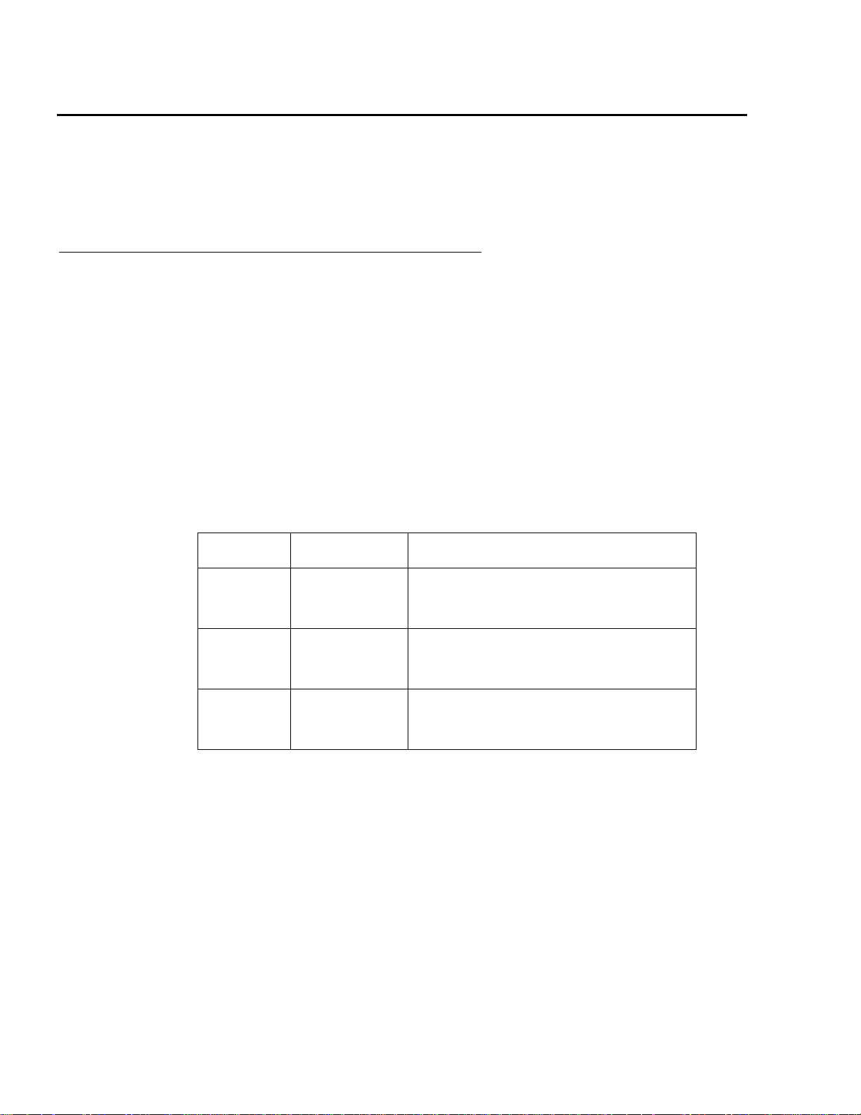
Item Problem Precaution
Wrist or
foot strap
ESD Wear a conductive wrist str ap or foot
strap when handling printed circuit
boards.
Cover
panels
Board slot
filler
panels
System
damage and
overheating
System
damage and
overheating
Reinstall all cabinet cover panels after
you perform any service work on the
system.
Make sure that a filler panel is installed
on all empty board slots.
22 Avaya CMS Sun Ultra 5 Computer Hardware Installation, Maintenance, and Troubleshooting
Page 23

System precautions
Ensure that the voltage and frequency of the power outlet used matches the electrical
rating labels on the equipment.
Wear antistatic wrist straps when handling any magnetic storage devices, and printed
circuit boards.
The Ultra 5 computer uses nominal input voltages of 100-240 V AC at 50-60 Hz. The
Ultra 5 should be powered by a non-switched, dedicated, 15-amp circuit. Sun products are
designed to work with single-phase power systems having a grounded neutral conductor
under safety precautions. To reduce the risk of electrical shock, do not plug Sun products
into another type of power so urce. Cont act your f aci lit ies manager or q uali fied elec tr ician if
you are unsure what type of power is supplied to your building.
A UPS provides a temporary electrical supply to a computer for several minutes,
depending on the number of components connected to the UPS. For a CMS computer,
a 2KVA minimum UPS is required for all installations. See your UPS documentation to
determine the projected amount of backup battery ti me fo r your model. If the system is
without power for longer than the backup time, the system may shut down improperly, and
the customer could lose data.
Preparing for installation
Each of the following items requires a separate power cord:
● Ultra 5 computer
● External peripherals
● Monitor
!
WARNING:
WARNING: DO NOT make mechanical or electrical modifications to the computer. Sun
Microsystems is not responsible for regulatory compliance of modified
computers.
Required tools
You need the following tools to do the installation:
● Phillips
● Needle-nose pliers
● ESD grounding wrist strap
● Antistatic mat
®
#2 screwdriver
Issue 3.3 February 2003 23
Page 24
Installation
Note:
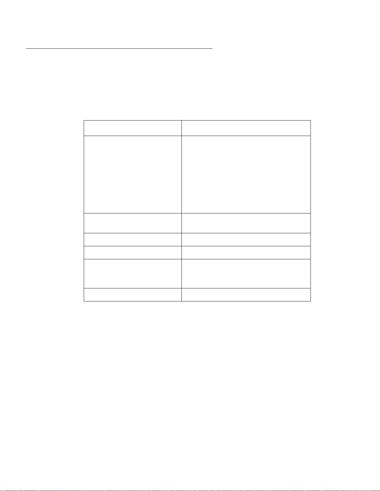
Electrical specifications
Note: For power integrity, an Uninterruptible Power Supp ly (UPS) is re commended
for all installa tions.
Parameter Value
Input current
- Voltage range
100-240 V AC, autosensing
(newer systems)
100 to 125 or 200 to 240 V AC, switch
selectable (older systems)
- Current, frequency range
- Current, maximum (120 V)
Input power rating (total
50-60 Hz
6A@120 V
200 W
continuous power)
Volt-ampere rating 300 VA
BTU rating 967 BTU
Wall plug type
- United States
- Non-United States
NEMA 5-15P
Power cords must be obtained locally
CPU plug type IEC 320
24 Avaya CMS Sun Ultra 5 Computer Hardware Installation, Maintenance, and Troubleshooting
Page 25

Physical specifications
Parameter English value Metric value
Height 4.4 inches 11.2 centimeters
Width 17.1 inches 43.6 centimeters
Depth 16.9 inches 43.0 centimeters
Weight 40 pounds 18 kilograms
Power cord 6.0 feet 1.8 meters
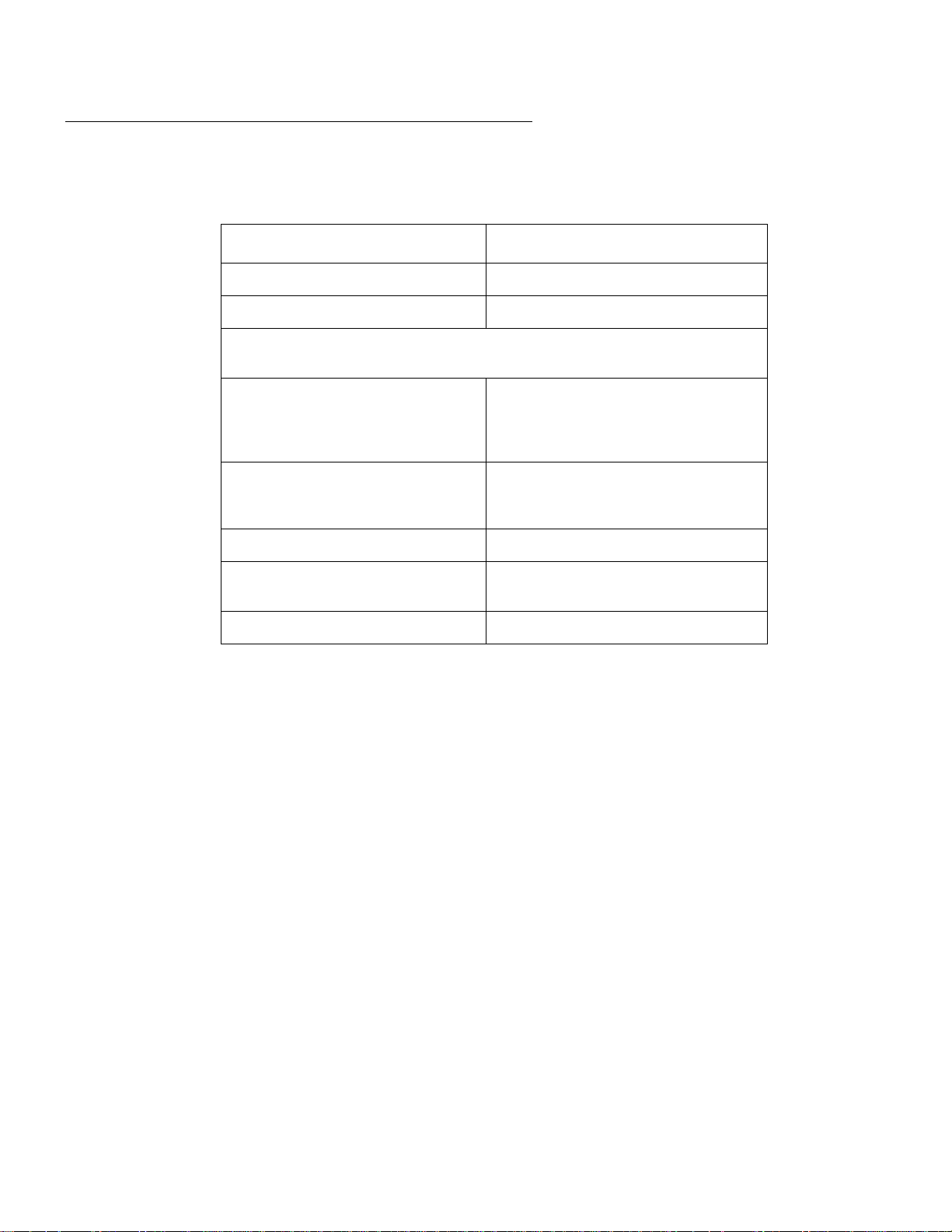
Environmental specificati ons
Preparing for installation
For the most reliable system operation:
● The room must have sufficient air conditioning capacity to support the cooling needs of
the entire system.
● The air conditioning system must have controls that preven t excessive temperature
changes.
Follow the guidelines in the table below for temperature, humidity, and altitude limits for
units in operation and for uni ts that are not in operation (t hat is, unit s that ar e in transi t or in
storage).
Parameter Operating Nonoperating
Temperature 41°F to 95°F (5°C to 35°C) -4°F to 140°F (-20°C to 60°C)
Humidity
(max)
Altitude (max) 10,000 feet (3 kilometers) 40,000 feet (12 kilometers)
20% to 80% RH
noncondensing
27°C max wb
93% RH
Issue 3.3 February 2003 25
Page 26
Installation
Miscellaneous specifications
Parameter Value
Operating acoustic noise 5.2 decibels
Idling acoustic noise 5.1 decibels
Declared noise emissions in accordance with ISO 9296, measured
at 23°C.
Safety UL 1950, CSA C22.2 No. 950,
RFI/EMI FCC Class B, DOC Class B, VCCI
TUV EN 60950, CB Scheme with
Nordic deviations, EMKO-TSE
(74-SEC) 203, ZH1/618
Class 2, EN 5502 Class B,
EN 61000-3-2
Immunity EN 50082-1
X-ray DHHS 21 Subchapter J; PTB
German X-ray Decree
Power Management Energy Star Compliant
26 Avaya CMS Sun Ultra 5 Computer Hardware Installation, Maintenance, and Troubleshooting
Page 27
Unpacking and inventorying the equipment
Note:
Unpacking and inventorying the equipment
!
WARNING:
WARNING: Never move the computer when the power is on. Excessive movement can
cause catastrophic disk drive failure. Always power the system OFF before
moving the computer.
!
WARNING:
WARNING: Always wear an electrostatic dischar ge (ESD) strap when handling internal
components.
Note: Always have up-to-date system backup s before turning the computer of f and
moving the computer.
Unpack the computer and associated peripher al equipment. Compare the contents of the
carton to the shipping inventory list to verify that all equipment was delivered.
Inspect all shipping cartons for evidence of physical damage. If a shipping carton is
damaged, request that the carrier repres entative be present before the carton is opened.
In the United S tates, contact the Services Support Organization (SSO) if any computer
parts are defective on arrival. Contact Avaya customer service if any computer parts are
missing.
Outside of the United States, contact your Avaya representative or di stributor if any
computer parts are missing or defective.
Issue 3.3 February 2003 27
Page 28

Installation
Parts list
Verify that you have the following component s of the Ultra 5 computer:
● Ultra 5 unit (including installed cards) and power cord
● Monitor and power cord
● Monitor cable
● Keyboard and cable
● Mouse and cable
● DDS4, 4-millimeter cartridge tapes (older systems will have QIC tapes)
— One blank tape for backups
— One tape that contains the factory configuration CMSADM filesystem backup
— One tape drive cleaning cartridge
In addition, other external components, disk drives and tape drives, may be part of the
order. V erify that all expected parts have been delivered.
28 Avaya CMS Sun Ultra 5 Computer Hardware Installation, Maintenance, and Troubleshooting
Page 29

Determining the computer model
This book is written for several different models of the Ultra 5 computer. The differences
between the models are few. This section describes how you can tell what model you
have.
Features
Each of the different models have distinctive features that will also assist you in
determining what model you have.
● Series 1
— 270 MHz CPU
— 4.2-GB internal boot disk (4500 RPM)
— 24X CD-ROM
— 8-bit graphics
Unpacking and inventorying the equipment
● Series 2
— 270 MHz CPU
— 4.2-GB internal boot disk (5400 RPM)
— 32X CD-ROM
— 24-bit graphics
● Series 3
— 360 MHz CPU
— 8.4-GB internal boot disk
— 32X CD-ROM
— 24-bit graphics
— 50ns RAM
— DDS4 external tape drive on newer models
— autosensing power supply on newer models
● Series 3, Model 400
— 400 MHz CPU
— 20-GB internal boot disk
— DDS4 external tape drive on all models
— autosensing power supply on all models
Issue 3.3 February 2003 29
Page 30

Installation
Physical labeling
Near the left-front corner of the computer, there is a label that has the seria l number and
other markings from the Sun factory. The models are marked as such:
● Series 1 – No special marking, just a serial number
● Series 2 – PGX24, plus the serial number
● Series 3 – Series 3, plus the serial number
● Series 3, Model 400 – BCD, Series 3, plus the serial number
Software check
Once the computer is operational, you can l og in as root and ent er the fol lo wing command
to identify the computer model:
prtconf -vp | grep SUNW,3
● Series 1 – model: SUNW,3.11
● Series 2 – model: SUNW,3.15
● Series 3 – model: SUNW,3.19
● Series 3, Model 400 – model: SUNW,3.25
30 Avaya CMS Sun Ultra 5 Computer Hardware Installation, Maintenance, and Troubleshooting
Page 31

Computer layout
Familiarize yourself with the layout of the computer.
Front Panel
This figure shows the front panel of the Ultra 5. The diskette drive is not available if the
optional second internal hard drive has been installed.
Unpacking and inventorying the equipment
System
3.5-inch bracket
unit
Diskette drive or second
internal hard drive
Rear Panel (with SunSwift® card)
This figure shows the r ear p ane l when y ou have a SunSwif t car d, whi ch is usual ly i nst alle d
in PCI slot 2. The SunSwift card has one 68-pin SCSI connector and one ethernet RJ45
connector. Other PCI cards may be installed in slots 1 and 3.
(spare)
Power
switch
SunSwift
card in
PCI slot 2
CD-ROM
drive
Standby
switch
PCI
slot 3
u5_front.cdr
PCI
slot 1
Power
supply fan
Voltage selector
switch (older
models only)
Power cord
receptacle
Audio
connectors
Serial
port B
Keyboard
connector
Parallel
printer
connector
Twisted-pair
Serial
port A
VGA
connector
Issue 3.3 February 2003 31
ethernet
connector
u5_back_sunswift.cdr
Page 32

Installation
Rear Panel (with UltraSCSI card)
This figure shows the rear panel when you have an UltraSCSI card, which is usually
installed in PCI slot 2. The UltraSCSI card has two 68-pin SCSI connectors. Other PCI
cards may be installed in slots 1 and 3.
Power
supply fan
Voltage selector
switch (older
models only)
Power
switch
Power cord
receptacle
UltraSCSI
card in
PCI slot 2
(left)
Audio
connectors
(left)
(right)
Keyboard
connector
Serial
port B
Serial
port A
PCI
slot 3
VGA
connector
PCI
slot 1
Parallel
printer
connector
Twisted-pair
ethernet
connector
u5_back_uscsi.cdr
32 Avaya CMS Sun Ultra 5 Computer Hardware Installation, Maintenance, and Troubleshooting
Page 33

Setting up power
To set up the AC power:
!
WARNING:
WARNING: DO NOT turn the computer on until you have verified that the input voltage
selector switch has been set properly. Incorrect voltages will damage
system components.
1. On the back of the computer, between the power cord receptacle and the power
switch, locate the voltag e selector switch. Newer models of the Ultra 5 use an
autosensing power supply and do not have a voltage selector switch.
Setting up power
Power
switch
Voltage selector
switch (older
models only)
Power cord
receptacle
u5_power.cdr
2. If your model has a voltage selector switch, set the voltage selector switch to 115
or 230 V AC depending on your installation.
3. Turn off the AC power switch on the back of the computer.
4. Plug the IEC 320 end of the power cord into the AC connector.
For installations out side of the Unit ed S t ates and Canada, obtain a power cor d for your
local configuration.
5. Plug the power cord from the computer into an outlet on the UPS.
A UPS provides a temporary electrical supply to a computer for several minutes,
depending on the number of components connected to the UPS. For a CMS compute r,
a 2KVA minimum UPS is required for all installations. See your UPS documentation to
determine the projected amount of back up batte ry time fo r y our model. If the syst em i s
without power for longer than the backup time, the system may shut down improperly,
and the customer could lose data.
If a UPS is not being used, you must use a grounded outlet on a dedicated 15-amp
circuit.
Issue 3.3 February 2003 33
Page 34

Installation
Peripheral connectivity
The following diagram shows how equipment is connected to the Ultra 5 when a SunSwift
card is installed. The callouts are described in Parts list
on page 36.
Remote console
Telephone line
to remote
maintenance center
System Console
Mouse
System console
External drives and
ethernet switch links
R
Keyboard
Monitor
Disk drive 1
(optional)
Target 0
Disk drive 2
(optional)
Target 1
Disk drive 3
(optional)
Target 2
Disk drive 4
(optional)
Target 3
Tape drive 1
(required)
Target 4
Tape drive 2
(optional)
Target 5
P
O
Modem
AB
C
G
G
Ethernet port for switch
link, R7 and later
(supports up to eight ACDs)
For detailed switch link
G
connectivity, see CMS Switch
Connections, Administration,
and Troubleshooting,
585-215-876
G
G
G
Serial port A is
used for single ACD
N
M
Sun
Ultra 5
Computer
D
SunSwift
Parallel
printer
Black Box
RS-449 - RS-232
interface converter
J
Black Box
J
RS-449 - RS-232
interface converter
I
HSI/P
H
S
SAI/P
Network
K
Q
K
L
64-port
NTS
NTS patch panel
(16 RS-232 Ports)
NTS patch panel
(16 RS-232 Ports)
An HSI/P card is used
for up to four ACDs.
A second HSI/P card
is needed for eight ACDs.
For detailed switch link connectivity, see
CMS Switch Connections, Administration,
and Troubleshooting, 585-215-876
SAI/P
T
expander box
(two maximum)
hub
NTS patch panel
(16 RS-232 Ports)
For detailed network hub and NTS
connectivity, see CMS Terminals,
Printers, and Modems, 585-215-874
K
L
16-port
NTS
To terminals,
printers,
modems
NTS patch panel
(16 RS-232 Ports)
X.25 switch links
printers, or modems
K
L
8-port
NTS
To terminals,
printers,
modems
To terminals,
8-port
NTS
no parallel
port
To terminals,
printers,
modems
K
To terminals,
printers,
modems
ultconp_sunswift.cdr
34 Avaya CMS Sun Ultra 5 Computer Hardware Installation, Maintenance, and Troubleshooting
Page 35

Peripheral connectivity
The following diagram shows how equipment is connected to the Ultra 5 when an
UltraSCSI card is installed. The callouts are described in Parts l ist
on page 36.
Remote console
Telephone line
maintenance center
System Console
Mouse
System console
External drives
P
to remote
Disk drive 1
(optional)
Target 0
Disk drive 2
(optional)
Target 1
Disk drive 3
(optional)
Target 2
Disk drive 4
(optional)
Target 3
Modem
Keyboard
Monitor
G
G
G
O
F
Tape drive 1
R
Tape drive 2
AB
C
(required)
Target 4
(optional)
Target 5
NOTE: The “Left/Right” designation for the
UltraSCSI card is based on the card
being in slot 2. If the UltraSCSI card is in
slot 1 or 3, connect the disk drives on the
right and the tape drives on the left.
Serial port A is
used for single ACD
N
M
Sun
Ultra 5
Computer
E
D
Ultra
SCSI
Left SCSI
Right
SCSI
F
G
Parallel
printer
Black Box
RS-449 - RS-232
interface converter
J
Black Box
J
RS-449 - RS-232
interface converter
I
HSI/P
H
SAI/P
S
K
K
Q
L
64-port
NTS
NTS patch panel
(16 RS-232 Ports)
An HSI/P card is used
for up to four ACDs.
A second HSI/P card
is needed for eight ACDs.
For detailed switch link connectivity, see
CMS Switch Connections, Administration,
and Troubleshooting, 585-215-876
T
Network
(16 RS-232 Ports)
SAI/P
expander box
(two maximum)
hub
NTS patch panel
For detailed network hub and NTS
connectivity, see CMS Terminals,
Printers, and Modems, 585-215-874
K
L
16-port
NTS
To terminals,
printers,
modems
NTS patch panel
(16 RS-232 Ports)
X.25 switch links
To terminals,
printers, or modems
K
L
8-port
NTS
To terminals,
printers,
modems
K
8-port
NTS
no parallel
port
To terminals,
printers,
modems
NTS patch panel
(16 RS-232 Ports)
To terminals,
printers,
modems
Issue 3.3 February 2003 35
ultconp.cdr
Page 36

Installation
Parts list
The following table lists parts that are required to connect most of the external devices to
the Ultra 5 computer. For i nfo rmation about connect ing termi nals , pri nters, and modems to
the Ultra 5 computer , see A vaya CMS Terminals, Printers, and Modems, 585-215 -874. For
information about switch connections for CMS, see Avaya CMS Switch Connections,
Administration, and Troubleshooting, 585-215-876.
Connectivity
diagram
call out
1
A
1
B
1
C
1
D
1
E
1
F
1
G
1
H
1
I
Comcode, or
Description
part of
comcode
2
N/A
Keyboard cable
Mouse with cable
Monitor cable
407938679 SunSwift card (10/100Mbps F/W UltraSCSI PCI Adapter)
408106664 UltraSCSI card (Dual-port PCI Adapter)
68-to-68 pin VHDCI cable (two provided)
407934470 68-to-68 pin SCSI cable and AC power cord
408128288 HSI/P card (up to two may be installed)
Quad cable (one per HSI/P card)
J 407086818 RS-449 cable (10 feet, 3 meters)
K 407086826 Category 5 UTP cord (10 feet, 3 meters)
L 407086859
CentreCOM
®
transceiver
M 846373413 DB9-to-RJ45 straight-through modem adapter
N 8469830 39 10-wire modular cable (10 feet, 3 meter s)
O 846362770 RJ45-to-DB25 remote console adapter
P 407633999
Varies
Sportster
Comsphere
®
33.6 remote console modem
®
3910 remote console modem
Q 408045326 Parallel printer cable
1
R
407925718
1
S
1
T
1. Sun Microsystems provides maintenance sparing for these parts.
408128247 SAI/P card (up to two may be installed)
N/A
N/A
2
DDS4 4mm tape drive (20/40-GB)
SLR5 QIC tape drive (4/8-GB)
XL/XS/DX 8mm tape drive (7/14-GB)
SAI/P expander box (one per SAI/P card)
2. The comcode fo r t his bun dle c ha nge s regularly and may n ot be ordered for main ten anc e s p ares, so
it is not listed in the table. This bundle includes the processor, peripherals, and other equipment.
36 Avaya CMS Sun Ultra 5 Computer Hardware Installation, Maintenance, and Troubleshooting
Page 37

Connecting the monitor and keyboard
!
Connecting the monitor and keyboard
The following figure shows how to connect the monitor and keyboar d to the Ult ra 5.
Key:
A = Keyboard cable
B = Mouse and cable
C = Monitor/video cable
VGA
connector
Mouse
Keyboard
connector
C
A
Monitor
Keyboard
B
u5_console.cdr
To connect the monitor and keyboard:
1. Make sure the computer power switch is set to off.
2. Connect the following components:
● Keyboard (connects to the keyboard connector)
● Mouse (connects to the keyboard)
● Monitor (connects to the VGA connector)
● Power cord (connects to the UPS or wall outlet)
This basic configuration represents the system console terminal.
CAUTION:
CAUTION: Once you have connected the keyboard and power-up the system, do not
disconnect the keyboard while the system is in operation. If the keyboard
becomes unplugged, see Keyboard becomes unplugged
on page 183 for
recovery procedures.
Issue 3.3 February 2003 37
Page 38

Installation
Connecting the remote console modem
This section describes how to connect the remote consol e modem to the computer. This
modem allows personnel at a remote support center to dial in and do maintenance on the
computer. The modem is a U.S. Robotics Sportster 33.6 Faxmodem, a Paradyne
Comsphere 3910 modem, or a modem provided locally.
The following figure shows remote console modem connectivity.
.
Key:
M = DB9-RJ45 adapter
N = Modular cord
O = RJ45-DB25 adapter
Telephone line
to remote
maintenance center
Modem
Modem
O
N
Serial
port B
M
u5_remconsole.cdr
To connect the remote console modem:
1. Connect the DB9-to-RJ45 straight-through adapter (M) to serial port B on the back of
the Ultra 5.
2. Connect the modular cord (N) to the RJ45 end of the adapter (M).
3. Connect the other end of the modular cord (N) to the RJ45 end of the RJ45-to-DB25
remote console adapter (O).
4. Connect the remote console adapter (O) to the RS-232C port on the modem. The
RS-232C port on the Comsphere 3910 is labeled “DTE1.”
5. Connect the telephone line to the jack labeled “LINE” on the Sportster modem, or
labeled “DIAL” on the Comsphere 3910 modem.
6. Connect the power cable to the modem and plug into a socket.
Do not turn the power on yet. Instructions for powering on the modem are given in Setting
the remote console modem options on page 50.
38 Avaya CMS Sun Ultra 5 Computer Hardware Installation, Maintenance, and Troubleshooting
Page 39

Connecting to external interfaces
Note:
A variety of external I/O components and interfaces may be required depending on the
configuration chosen by the customer. This section describes some of the most likely
configurations.
Refer to the following subsections as appropriate for your installation:
● Connecting the switch link on page 3 9
● Connecting the serial port expand er box on page 40
● Connecting external SCSI devices on page 41
Procedures for connecting a network hub unit and an NTS are found in Avaya CMS
Terminals, Printers, and Modems, 585-215-874.
Connecting the switch link
Connecting to external interfaces
There are two ways to connect the CMS computer to a switch:
● using TCP/IP over a local area network (LAN)
● using X.25 protocol over a hard-wired or switched link
Note: Some CMS loads do not support the X.25 protocol. Contact the National
Customer Care Center or consult with your product distributor or
representative to veri fy if the X.25 protocol is supported on your CMS
system.
One CMS computer can collect data from up to eight different switches. To the CMS
computer, each switch represents one ACD. Depending on the release of the switch and
the release of the CMS software, you can have all switches co nnected using TCP/IP, all
switches connected using X.25 protocol, or some combination of the two protocols.
For detailed informati on about how to connect and administer the switch link, see Avaya
CMS Switch Connections, Administration, and Troubleshooting, 585-215-876.
Issue 3.3 February 2003 39
Page 40

Installation
Connecting the serial port expander box
To connect serial devices to the Ultra 5, you can use a Serial Asynchronous Interface/PCI
(SAI/P) expander box. The SAI/P car d is us ed to connect t ermi nals, pr inter s, and modems
to the computer. Each SAI/P card is shipped with an expander box that attaches to the
SAI/P card and breaks out eight RS232 serial ports (see the figure below). There can be
up to two SAI/P cards and expander boxes on each Ultra 5.
SAI/P card
SAI/P expander
box
u5_saip_box.cdr
40 Avaya CMS Sun Ultra 5 Computer Hardware Installation, Maintenance, and Troubleshooting
Page 41

Connecting external SCSI devices
This section describes how to connect the SCSI devices (tape drives and disk drives) to
the Ultra 5 computer. SCSI devices connect to eithe r the SunSwi ft card or to the
Dual-Channel UltraSCSI card.
SunSwift connections
The following figure shows how to connect UniPack SCSI disk drives and tape drives to a
SunSwift card. A 68-to-68-pin SCSI cable connects from the SunSwift PCI card on the
back of the computer to the IN connector on the back of the SCSI device that is clo sest to
the computer. If you have more than one SunSwift card, connect the drives to the card in
the lowest slot number. A 68-to-68 pin SCSI cable connects from the OUT connector of
that device to the IN connector of the next device. Continue this process until all assigned
devices are connected in the SCSI chain.
.
Stack of three
external SCSI devices
68-to-68 pin SCSI cable
Connecting to external interfaces
scsi_sunswift.cdr
Target
address
switch
IN
IN
IN
OUT
OUT
OUT
Back panel of Ultra 5
SunSwift card
in PCI slot 2
68-to-68 pin SCSI cable
When connecting SCSI devices, the last device in the chain MUST be terminat ed, either
via an auto-terminated device or with a manual terminat or.
When using an auto-terminated SCSI device, you do not need to connect a SCSI
terminator to the OUT connector of t he last SCSI de vic e in t he chain. To verify that the las t
device is auto-terminated, check the LEDs labeled Auto Term High and Auto Term Low on
the back panel of the device. In a CMS configurati on, both LEDs are lit on the last device in
the SCSI chain. If a device in the SCSI chain is not the last device, neither termina tion LED
is lit.
When using a manually-terminated device, you must connec t a SCSI termi nator to the
OUT connector of the last SCSI device in the chain. When you connect the SCSI
terminator to the OUT connector, the LED on the terminator is lit.
Issue 3.3 February 2003 41
Page 42

Installation
The following figure shows the SCSI cabling schemes that are poss ibl e with a SunSwift
card that is installed in an Ultra 5 computer.
SCSI
Connector
scsicble_swift.cdr
UniPack Disk
Drive 1
(optional)
W
68-68 68-68
UniPack Disk
Drive 2
(optional)
WW W
W
68-68
UniPack Disk
Drive 3
(optional)
W
W
UniPack Disk
Drive 4
(optional)
W
68-68
SCSI devices are addressed as shown in the following table.
Device Address
Disk drive 1 0
Disk drive 2 1
Disk drive 3 2
Disk drive 4 3
Tape drive 1 4
Tape drive 2 5
UniPack
Tape Drive 1
(required)
W
W
68-68
W = 68-68 pin SCSI cable
A = Auto-terminated
W
68-68
UniPack
Tape Drive 2
(optional)
W
A
!
!
Important:
Important:
Important: Do not use a target address
greater than 5.
The addresses are set using the target addr ess switches on the back of each SCSI device.
Before setting the target address, make sure that the power is off on the SCSI devices.
Press this side to decrease
the address number.
+
2
Press this side to increase
the address number.
scsiidsw.cdr
42 Avaya CMS Sun Ultra 5 Computer Hardware Installation, Maintenance, and Troubleshooting
Page 43

UltraSCSI connections
The following figure shows how to connect UniPack SCSI disk drives and ta pe drives to an
UltraSCSI card. A 68-to-68-pin VHDCI SCSI cable connects from the UltraSCSI PCI card
on the back of the computer to the IN connector on the back of the SCSI device that is
closest to the computer. A 68-to-68 pin SCSI cable connects from the OUT connector of
that device to the IN connector of the next device. Continue this process until all assigned
devices are connected in the SCSI chain.
Stack of three
external SCSI devices
68-to-68 pin SCSI cable
Connecting to external interfaces
scsiuni.cdr
Target
address
switch
IN
IN
IN
OUT
OUT
OUT
68-to-68 pin VHDCI cable
Back panel of Ultra 5
(right)
(left)
Dual-channel
UltraSCSI card in PCI slot 2
When connecting SCSI devices, the last device in the chain MUST be terminat ed, either
via an auto-terminated device or with a manual terminat or.
When using an auto-terminated SCSI device, you do not need to connect a SCSI
terminator to the OUT connector of t he last SCSI de vic e in t he chain. To verify that the las t
device is auto-terminated, check the LEDs labeled Auto Term High and Auto Term Low on
the back panel of the device. In a CMS configurati on, both LEDs are lit on the last device in
the SCSI chain. If a device in the SCSI chain is not the last device, neither termina tion LED
is lit.
When using a manually-terminated device, you must connec t a SCSI termi nator to the
OUT connector of the last SCSI device in the chain. When you connect the SCSI
terminator to the OUT connector, the LED on the terminator is lit.
Issue 3.3 February 2003 43
Page 44

Installation
Note:
The following figure shows the SCSI cabling schemes that are poss ible with an UltraSCSI
card that is installed i n slot 2 of an Ultr a 5 computer.
UniPack Disk
Drive 4
(optional)
W A
68-68
scsicble.cdr
68-68
UniPack Disk
Drive 3
(optional)
W
W
V = 68-68 pin VHDCI cable
W = 68-68 pin SCSI cable
A = Auto-terminated
Left SCSI
Connector
V
68-68
Right SCSI
Connector
V
68-68
Note: The “Left/Right” designations shown above are based on the UltraSCSI card
Drive 1
(optional)
V
UniPack
Tape Drive 1
(required)
V
W W
W W
68-68
UniPack Disk
UniPack Disk
Drive 2
(optional)
W
68-68
UniPack
Tape Drive 2
(optional)
A
being installed in slot 2. If the UltraSCSI car d is in stalled in slots 1 or 3,
connect the disk drives to the right connector and the tape drives to the left
connector.
44 Avaya CMS Sun Ultra 5 Computer Hardware Installation, Maintenance, and Troubleshooting
Page 45

Connecting to external interfaces
SCSI devices are addressed as shown in the following table.
Device Address
Disk drive 1 0
Disk drive 2 1
Disk drive 3 2
Disk drive 4 3
Tape drive 1 4
Tape drive 2 5
!
!
Important:
Important:
Important: Do not use a target address
greater than 5.
These addresses are set using the target addr ess switches on the back of each SCSI
device. Before setting the target address, make sure that the power is off on the SCSI
devices.
Press this side to decrease
the address number.
+
2
Press this side to increase
the address number.
scsiidsw.cdr
Issue 3.3 February 2003 45
Page 46

Installation
Note:
Turning the system on and verifying POST
Once you assemble the system, including the external devi ces that are shipped with your
system, turn the system on and verify POST (Power On Self Test).
To turn the system on and verify POST:
1. Plug the power cord of the UPS into an AC outlet.
2. Turn on the power to the UPS.
3. Turn on all external SCSI devices star ting with the dev ice farthest from the syst em and
working toward the system.
4. Turn on the system monitor .
5. Turn on the system.
Note: The POST diagnostics will occur each time you turn on the system. The
POST tests the basic system components. This may take several minutes
6. While the system is booting up, press Stop+A simultaneously to put the system in the
monitor mode.
The ok prompt is displayed.
7. Enter the following commands:
setenv auto-boot? false
reset-all
The system resets to the ok prompt.
46 Avaya CMS Sun Ultra 5 Computer Hardware Installation, Maintenance, and Troubleshooting
Page 47

Turning the system on and verifying POST
Note:
8. Enter:
probe-ide
This verifies that the system sees all enhanced integrated drive electronics (EIDE)
devices. A message similar to the following is displayed:
Device 0 ( Primary Master )
ATA Model: STxxxxxx
Device 1 ( Primary Slave )
Not Present (or) ATA Model: STxxxxxx
Device 2 ( Secondary Master )
Removable ATAPI Model: CRD-xxxxx
Device 3 ( Secondary Slave )
Not Present (or) Removable ATAPI Model: xxxx
In this example, the devices listed are as foll ows:
● Device 0 is the primary internal hard drive.
● Device 1 is the optional second internal hard dri ve, if present.
● Device 2 is the CD-ROM drive.
● Device 3 is the floppy drive, if present.
Note: The actual devices listed depends on the devices installed on the EIDE bus.
9. Enter:
reset-all
The system resets to the ok prompt.
Issue 3.3 February 2003 47
Page 48

Installation
Note:
!
10. Enter:
probe-scsi-all
This verifies that the system sees all external SCSI devices. A message similar to the
following is displayed:
/pci@1f,0/pci@1/pci@1/SUNW,isptwo@4
Target 0
Unit 0 Disk QUANTUM VK4550J SUN4.2G8610
Target 4
Unit 0 Removeable Tape HP C5683A C911
In this example, the devices listed are as follows:
● Target 0 is an external 4.2-GB hard drive.
● Target 4 is an external DDS4 tape drive.
Note: The actual devices listed depends on the devices installed on the SCSI bus.
11. When you have verified that the system recognizes all of its devices, enter the
following commands:
CAUTION:
CAUTION: If you fail to enter these commands, any reboots that you do in the future will
stop at the boot prompt instead of proceeding through the normal boot-up
process.
setenv auto-boot? true
boot -r
The system reboots.
48 Avaya CMS Sun Ultra 5 Computer Hardware Installation, Maintenance, and Troubleshooting
Page 49

Identifying installed PCI cards
Identifying installed PCI cards
If there are proble ms wi th th e PCI cards, do the f ollowi ng to t roublesho ot the pr oble m. If al l
PCI cards are operational, you can skip this section.
At the command prompt, enter:
/usr/platform/‘uname -m‘/sbin/prtdiag -v | pg
In the section called IO Cards, there is a listing of the PCI cards. The following are
examples of some of the entries you may see. The display you see depends on your
specific configuration.
.
.
========================= IO Cards =========================
Bus# Freq
Brd Type MHz Slot Name Model
--- ---- ---- ---- -------------------------------- --------------------- 0 PCI-1 33 1 ebus
0 PCI-1 33 1 network-SUNW,hme
0 PCI-1 33 2 SUNW,m64B ATY,GT-B
0 PCI-1 33 3 ide-pci1095,646
0 PCI-2 33 1 pci114f,1c-pci114f,1c
0 PCI-2 33 2 pci-pci1011,24
0 PCI-2 33 3 pci1214,334-pci1214,334
.
.
In this example:
● Slot 1 is an SAI/P card
● Slot 2 is a SunSwift card
● Slot 3 is an HSI/P card
Issue 3.3 February 2003 49
Page 50

Installation
Setting the remote console modem options
The computer supports the U.S. Robotics Sportster 33.6 Faxmodem and the Paradyne
Comsphere 3910 modem for remote console access. The options for any other modems
must be set based on local instructions.
For instructions for co nnecting the modem, see Con necting the remote console modem
page 38.
Sportster 33.6 faxmodem
The Sportster 33.6 faxmodems are optioned at the factory. Use this procedure only if the
modem has lost the factory option settings.
To set the options for the Sportster 33.6 faxmodem:
1. Set DIP switches 1, 3, 7, and 8 on the back panel of the Sportster modem to the down
(ON) position, and switches 2, 4, 5, and 6 to the up (OFF) position.
2. Turn on the remote console modem.
3. At the system console, log in as root.
4. Enter:
/cms/install/bin/abcadm -r ttyb
The following message is displayed:
ttyb is currently set to be incoming
on
Are you sure you want to change it? [y,n,?]
5. Enter:
50 Avaya CMS Sun Ultra 5 Computer Hardware Installation, Maintenance, and Troubleshooting
y
The following message is displayed:
ttyb administration removed
The port monitor turns off.
Page 51

Setting the remote console modem options
Note:
6. Enter the following command:
cu -s 9600 -b 8 -l cua/b
The following message is displayed:
Connected
7. Enter the following commands:
at&f1 (loads the factory default configuration into active memory)
at&w0 (writes the current configuration to NVRAM template Y0)
Note: Use numerical ones and zeros when entering the options.
8. After you enter the options, disconnect from the modem by entering a tilde and a
period (~.).
9. Set DIP switches 4 and 8 on the back panel of the Sportster modem to the down (ON)
position. Set all other DIP switches to the up (OFF) posi tion.
10. Reset the modem by turning the power off and back on.
11. Enter:
/cms/install/bin/abcadm -i -b 9600 ttya
The Terminal Ready (TR) LED lights on the modem and the following message is
displayed:
ttya set to incoming port 9600 baud
12. If the TR LED is not lit, enter:
ps -ef | grep sac
A message similar to the following should be displayed:
root 377 1 0 14:39:30 ? 0:00 /usr/lib/saf/sac -t 300
root 9723 9666 0 09:16:26 pts/9 0:00 grep sac
Additional references – For additional information, see the U.S. Robotics Sportster
Modems Users Guide.
Issue 3.3 February 2003 51
Page 52

Installation
S
Paradyne Comsphere 3910 modem
The Paradyne Comsphere 3910 modem is used for many locations outside of the United
States. These modems are not opti oned at the factory.
Recommended options
The recommended options for the Comsphere 3910 modem include selecting the
factory-preset defaults for “UNIX_Dial” with the following two changes:
● Asynchronous DTE Rate is changed to 9600
● Dial Line Rate is changed to 9600 (V32b)
Option buttons
The seven buttons that are used to set the modem options include:
● Single Up Arrow. Move up one level in the menu tree
● Double Up Arrow. Move to the top-level menu
● Left Arrow. Move to the previous choice for the current level in the menu tree
● Right Arrow. Move to subsequent choice for the current level in the menu tree
● Function 1 (F1). Select the choice, if any, that is currently displayed above F1
● Function 2 (F2). Select the choice, if any, that is currently displayed above F2
● Function 3 (F3). Select the choice, if any, that is currently displayed above F3
ingle Up
Arrow
Double Up
Arrow
Right
Arrow
Left
Arrow
Function keys
52 Avaya CMS Sun Ultra 5 Computer Hardware Installation, Maintenance, and Troubleshooting
3910.cdr
Page 53

Setting the options
To set the options on the Comsphere 3910, use the following procedures.
Configuring Factory/Async_Dial
1. Press F2 to select “Configure.”
“Ld EditArea frm” is displayed.
2. Press the Right Arrow four times.
“Factory” is displayed.
3. Press F1 to select “Factory.”
“Ld Fact Preset:” is displayed.
4. Press Right Arrow four times.
5. Press F1 to select “UNIX_Dial.”
6. Press F3 to select “Save.”
“Sav EditArea to” is displayed.
Setting the remote console modem options
7. Press F1 to save to “Active(Saved).”
Since you are changing the active area to a new set of options (th at is,
“Factory/Async_Dial”), the modem aut omatically performs another Power-On-Self-Test
(POST). Since the new options match the way the modem is connected, the ALRM
LED does not turn red. “Idle: 19.2” and “Status Configure” are displayed. To return to
the top-level menu, press the Double Up Arrow.
Setting the data rate
1. Press F2 to select “Configure.”
“Ld EditArea frm” is displayed.
2. Press the Right Arrow once.
“Active(Saved)” is displayed.
3. Press F1.
“Choose Function” is displayed.
4. Press F1 to select “Edit.”
“Edit StrapGroup” is displayed.
5. Press F1 to select “DTE_Interface.”
“Async/Sync Mode” is displayed.
6. Press F1 to select “Nxt.”
“Async DTE Rate” is displa ye d .
Issue 3.3 February 2003 53
Page 54

Installation
7. Press the Right Arrow five times to display “9600.”
8. Press F2 to select “9600.”
Setting the handshake options
1. Press F1 for “Nxt.”
“Asyn #Data Bits (8)” is displayed.
2. Press F1 for “Nxt.”
“Asyn Parity Bit (None)” is displayed.
3. Press F1 for “Nxt.”
“Asyn #Stop Bits (1)” is displayed.
4. Press F1 for “Nxt.”
“DTR Action (Ignore)” is displayed.
5. Press F1 for “Nxt.”
“DSR Control (Forced_On)” is displayed.
6. Press F1 for “Nxt.”
“RTS Action (Ignore)” is displayed.
7. Press F1 for “Nxt.”
“CTS Control (WinkWhenDisc)” is displayed.
8. Press F1 for “Nxt.”
“RTS/CTS Delay (0 msec)” is displayed.
9. Press F1 for “Nxt.”
“LSD Control (WinkWhenDisc)” is displayed.
10. Press F1 for “Nxt.”
“CT111_Rate Cntl (Disable)” is displayed.
11. Press F1 for “Nxt.”
“DTE_Rate=VF (Disable)” is displayed.
12. Press F1 for “Nxt.”
“Extend Main Ch. (Disable)” is displayed.
13. Press F1 for “End .”
“Edit StrapGroup” is displayed.
54 Avaya CMS Sun Ultra 5 Computer Hardware Installation, Maintenance, and Troubleshooting
Page 55

Setting the remote console modem options
Setting the Dial_Line strap group
1. Press the Right Arrow three times to get to the “Dial _Line” strap group. Nothing need s
to be changed for CMS in the “DTE_Dialer” or “Line_Dialer” strap groups, so you can
skip them.
2. Press F1 to edit the “Dial_Line” strap group.
“Dial Line Rate” is displayed .
3. Press the Right Arrow four times for “9600(V32b).”
4. Press F2 to select “9600(V32b).”
5. Press F1 for “Nxt.”
“V32bis Automode (Enable)” is displayed.
6. Press F1 for “Nxt.”
“V32bis Autorate (Enable)” is displayed.
7. Press F1 for “Nxt.”
“Dial Tx Level (Permissv (-9))” is d isplayed.
8. Press F1 for “Nxt.”
“V22b Guard Tone (Disable)” is displayed.
9. Press F1 for “Nxt.”
“V32bis Train (Long)” is displayed.
10. Press F1 for “End .”
“Edit StrapGroup” is displayed. The other strap groups (“V42/MNP/Buffer,” “Test,”
“Misc,” and “Security”) are not changed for CMS.
Saving your settings
1. Press the Single Up Arrow to display “Choose Function” and “Edit Save.”
2. Press F3 to select “Save.”
“Save EditArea to” is displayed.
3. Press F1 to select “Active(Saved).”
“Command Complete” is displayed.
4. Press the Single Up Arrow again to display “Save EditArea to.”
5. Press the Right Arrow once to select “Customer 1.”
6. Press F1 to save to “Customer 1.”
“Command Complete” is displayed.
Issue 3.3 February 2003 55
Page 56

Installation
7. Press the Double Up Arrow.
“Idle: 9600” and “Status Configure” are displayed. If the modem is powered off, it
should return to this state when it is powered on.
8. To check the status of the Comsphere 3910 modem, use the “Status” choice in the
top level menu, or use the Right and Left Arrow butt ons to view other top-level menu
choices.
56 Avaya CMS Sun Ultra 5 Computer Hardware Installation, Maintenance, and Troubleshooting
Page 57

Turning the system over for provisioning
Turning the system over for provisioning
After completing the physical installation of the system, the installation continues with
software provisioning . This is often done with the support of the Avaya CMS Provisioning
group. Provisioning the system consists of the following:
● Setting up CMS
● Authorizing features
● Adding logins and passwords
● Testing the software
To continue with provisioning, see the chapter “T urning th e system over to the customer” in
the software insta llat ion, maintenance, and tr oubleshoot in g document appropr iate for your
version of CMS.
Issue 3.3 February 2003 57
Page 58

Installation
58 Avaya CMS Sun Ultra 5 Computer Hardware Installation, Maintenance, and Troubleshooting
Page 59

Maintenance
Overview
This chapter describes the following maintenance procedures:
● Computer layout on page 60
● ESD precautions on page 63
● Maintaining PCI cards on page 64
● Maintaining disk drives on page 83
● Replacing the CD-ROM drive on page 130
● Maintaining tape drives on page 135
● Adding memory and replacing the CPU on page 147
Issue 3.3 February 2003 59
Page 60

Maintenance
Computer layout
Familiarize yourself with the layout of the Ultra 5.
Front Panel
This figure shows the front panel of the Ultra 5. The diskette drive is not available if the
optional second internal hard drive has been installed.
System
unit
3.5-inch bracket
(spare)
Diskette drive or second
internal hard drive
CD-ROM
drive
Standby
switch
u5_front.cdr
60 Avaya CMS Sun Ultra 5 Computer Hardware Installation, Maintenance, and Troubleshooting
Page 61

Rear Panel (with SunSwift c a rd)
This figure shows the r ear p ane l when y ou have a SunSwif t car d, whi ch is usual ly i nst alle d
in PCI slot 2. The SunSwift card has one 68-pin SCSI connector and one ethernet RJ45
connector. Other PCI cards may be installed in slots 1 and 3.
Computer layout
Power
supply fan
Voltage selector
switch (older
models only)
Power
switch
Power cord
receptacle
SunSwift
card in
PCI slot 2
Audio
connectors
Serial
port B
Keyboard
connector
Serial
port A
PCI
slot 3
VGA
connector
PCI
slot 1
Parallel
printer
connector
Twisted-pair
ethernet
connector
u5_back_sunswift.cdr
Issue 3.3 February 2003 61
Page 62

Maintenance
Rear Panel (with UltraSCSI card)
This figure shows the rear panel when you have an UltraSCSI card, which is usually
installed in PCI slot 2. The UltraSCSI card has two 68-pin SCSI connectors. Other PCI
cards may be installed in slots 1 and 3.
Power
supply fan
Voltage selector
switch (older
models only)
Power
switch
Power cord
receptacle
UltraSCSI
card in
PCI slot 2
(left)
Audio
connectors
(left)
(right)
Keyboard
connector
Serial
port B
Serial
port A
PCI
slot 3
VGA
connector
PCI
slot 1
Parallel
printer
connector
Twisted-pair
ethernet
connector
u5_back_uscsi.cdr
62 Avaya CMS Sun Ultra 5 Computer Hardware Installation, Maintenance, and Troubleshooting
Page 63

ESD precautions
Before you work on components inside the Ultra 5 computer:
1. Make sure that the computer is plugged in to AC power.
2. Make sure that the power is off.
3. Attach the Electro-Static Discharge (ESD) wrist strap to the chassi s frame and to your
wrist. See the following figure.
ESD precautions
PCI slot 2
screws
4. Unplug the AC power cord.
u5_wriststrap.cdr
Issue 3.3 February 2003 63
Page 64

Maintenance
Maintaining PCI cards
Overview
Procedures in this section include the following:
● Identifying free card slots
● PCI card configuration on page 65
● Installing or remov ing PCI cards on page 66
● Replacing an UltraSCSI card with a SunSwift card on page 68
● SAI/P cards o n pag e 7 1
● Installing HSI/P cards on page 77
Required references
You need access to the following documents to do procedures in this section:
● Avaya CMS R3V11 Software Installation, Maintenance, and Troubleshooting,
585-215-115
● Avaya CMS R3V9 Software Installation, Maintenance, and Troubleshooting,
585-215-956
● Avaya CMS R3V8 Software Installation, Maintenance, and Troubleshooting,
585-210-941
● Avaya CMS Software Installation and Setup (R3V5 and R3V6), 585-215-866
● Avaya CMS Switch Connections, Administration, and Troubleshooting, 585-215-876
● Sun Ultra 5 Service Manual
Identifying free card slots
There are three PCI slots on the back of the Ultra 5 computer. Empty slots are covered by
filler panels. Every computer will have eit her a SunSwift SCSI/Ethernet or UltraSCSI card
installed in Slot 2.
64 Avaya CMS Sun Ultra 5 Computer Hardware Installation, Maintenance, and Troubleshooting
Page 65

PCI card configuration
Note:
Depending on your configuration, the PCI cards will be installed in the slots shown below.
Card PCI Slot Comments
Maintaining PCI cards
SunSwift
or
PCI 2, 1,
or 3
UltraSCSI
HSI/P PCI 1 or
PCI 3
SAI/P PCI 1 or
PCI 3
Required. A SunSwift card is installed in every
computer to provide a dedicated ethernet
connection to the switch, and a SCSI interface to
external tape and disk drives. Additional SunSwift
cards can be installed in the other slots.
Optional. HSI/P cards are not required when
using ethernet for switch link connectivity. Use
PCI 1 for the first card, which supports four ACDs.
Use PCI 1 and 3 for two cards, which support
eight ACDs.
Note: Some CMS loads do not support
the X.25 protocol. Contact th e
National Customer Care Center or
consult with your product
distributor or representative to
verify if the X.25 protocol is
supported on your CMS system.
Optional. SAI/P cards provide serial port
connectivity for printers and ter m inals. Use PCI 1
for the first card, which supports eight serial
devices. Use PCI 1 and 3 for two cards, which
supports 16 serial ports.
Token Ring PCI 3 Optional. Installa tion and setup of this card is
done by Professional Services in the United
States, or by special arrangement outside of the
United States.
Issue 3.3 February 2003 65
Page 66

Maintenance
Note:
Installing or removing PCI cards
Use the following general instructions when installing, moving, and removing PCI cards.
Other sections in this chapter describe specific PCI card maintenance instructions. Use
those instructions as appropriate.
Note: If you plan to install an optional second internal hard drive, inst all it before
you install any PCI cards.
To install or remove a card:
1. For a system currently in operation, verify that you have a recen t CMSADM file system
backup before you change card configurations.
2. Enter:
/usr/sbin/shutdown -y -i0 -g0
This shuts down the system.
3. Turn off the system.
4. Turn off the system monitor.
5. Turn off all external SCSI devices starting with the device closest to the system and
working toward the farthest device.
!
WARNING:
WARNING: You must wear an ESD wrist strap when installing or removing hardware
components to prevent electrical discharge that can damage the system.
6. Remove the cover of the Ultra 5.
7. Disconnect the AC power cord.
8. Select an unused slot to add a card, or select what card you are removing.
66 Avaya CMS Sun Ultra 5 Computer Hardware Installation, Maintenance, and Troubleshooting
Page 67

9. Add or remove the card as shown in the following figure.
PC riser
board
PCI slot 2
PCI slot 3
PCI slot 1
u5_pcicard.cdr
10. Remove the ESD wrist strap.
Maintaining PCI cards
PCI card
Screw
11. Reattach the cover.
12. Reconnect the AC power cord.
13. Turn on all external SCSI devices starting wit h the device farthest fr om the system and
working toward the system.
14. Turn on the system monitor.
15. Turn on the system.
16. Press Stop+A simultaneously after the console banner is displayed, but before the
system starts boot ing.
17. Enter:
boot -r
This reboots the system so that it recognizes the new configuration.
18. Perform a CMSADM file system backup to back up the updated system configuration.
See your CMS software installation, maintenance, and troubleshooting document for
details.
Issue 3.3 February 2003 67
Page 68

Maintenance
Replacing an UltraSCSI card with a SunSwift card
This section describes how to replace an UltraSCSI card with a SunSwift card. This is done
when the customer wants to add a second ethernet port.
Prerequisites
● Obtain a SunSwift PCI card.
● Obtain one or two 68-to-68 pin SCSI cables (comcode 407934470, part
number 595-4851-xx).
● Do a CMSADM backup.
● Turn off CMS before beginning this procedure.
Procedure
To replace an UltraSCSI card with a SunSwift card:
1. Enter:
/usr/sbin/shutdown -y -i0 -g0
This shuts down the system.
2. Turn off the system.
3. Turn off the system monitor.
4. Turn off all external SCSI devices starting with the device that is closest to the system
and working toward the farthest device.
!
WARNING:
WARNING: You must wear an ESD wrist strap when installing or removing hardware
components to prevent electrical discharge that can damage the system.
5. Disconnect each 68-to-68 pin VHDCI cable from the UltraSCSI card and from the first
external device in each existing SCSI chain. There may be one chain of disk drives
and one chain of tape drives.
6. Remove the cover of the Ultra 5.
7. Disconnect the AC power cord.
68 Avaya CMS Sun Ultra 5 Computer Hardware Installation, Maintenance, and Troubleshooting
Page 69

8. Remove the UltraSCSI card. It should be located in PCI slot 2.
PC riser
board
PCI slot 2
PCI slot 3
PCI slot 1
u5_pcicard.cdr
Maintaining PCI cards
PCI card
Screw
SCSI
Connector
scsicble_swift.cdr
9. Install the SunSwift card in PCI slot 2 (or wherever the UltraSCSI card was installed).
10. Reconfigure the SCSI devices in the order shown in the following figure.
UniPack Disk
Drive 1
(optional)
W
68-68 68-68
UniPack Disk
Drive 2
(optional)
WW W
W
68-68
UniPack Disk
Drive 3
(optional)
W
UniPack Disk
Drive 4
(optional)
W
W
68-68
W
68-68
UniPack
Tape Drive 1
(required)
W
W = 68-68 pin SCSI cable
A = Auto-terminated
W
68-68
UniPack
Tape Drive 2
(optional)
W
A
Issue 3.3 February 2003 69
Page 70

Maintenance
SCSI devices are addressed as shown in the table below. These addresses are set
using the Target Address Switches on the back of each SCSI device.
Device Address
Disk Drive 1 0
Disk Drive 2 1
Disk Drive 3 2
Disk Drive 4 3
Tape Drive 1 4
Tape Drive 2 5
!
!
Important:
Important:
Important: Do not use a target address
greater than 5.
11. Remove the ESD wrist strap.
12. Reattach the cover.
13. Reconnect the AC power cord.
14. Turn on all external SCSI devices start ing with the device that is farthest from the
system and working toward the system.
15. Turn on the system monitor .
16. Turn on the system.
17. Press Stop+A simultaneously after the console banner is displayed, but before the
system starts booting.
18. Enter:
boot -r
This reboots the system so that it recognizes the new configuration.
19. Perform a CMSADM file system backup to back up the updated system configuration.
See your CMS software installation, maintenance, and troubleshooting document for
details.
70 Avaya CMS Sun Ultra 5 Computer Hardware Installation, Maintenance, and Troubleshooting
Page 71

SAI/P cards
The Serial Asynchronous Interface/PCI (SAI/ P) card connects terminals, printers and
modems to the computer. The computer can accommodate two SAI/P cards. Each SAI/P
card is associated with an external, 8- port expander box.
Identifying device entry names for ports on an SAI/P card
When the SAI/P card driver is installed, device entries are created to access the physical
ports on the expander box. The device name that is cre ated is /dev/term/N, where N
represents SAI/P slot and expander box port entries. For example, when two SAI/P cards
are installed, the card in the lowest numbered slot is associated with physical ports
a000-a007, while ports for the second card are denoted by b000-b007.
To display the port designations for each SAI/P card, use the
/cms/toolsbin/display_ports command. A response similar to the following is
displayed:
Maintaining PCI cards
/dev/term devices:a000 a001 a002 a003 a004 a005 a006 a007
#
Adding, moving, or removing an SAI/P card
This section describes how to add, remove or move an SAI/P card.
Adding an SAI/P card – To add an SAI/P card:
1. Identify the existing SAI/P cards installed in the system.
2. Verify that you have a recent CMSADM file system backup before you change card
configurations.
3. Enter:
/usr/sbin/shutdown -y -i0 -g0
This shuts down the system.
4. Turn off the system.
5. Turn off the system monitor.
6. Turn off all external SCSI devices starting with the device that is closest to the system
and working toward the farthest device.
7. Decide where you will install the new SAI/P car d. Insert the SAI/P car d i nto t he Ultr a 5.
See Installing or removing
8. Connect the expander box to the new SAI/P card.
PCI cards on page 66 for more information.
Issue 3.3 February 2003 71
Page 72

Maintenance
9. Turn on all external SCSI devices start ing with the device that is farthest from the
system and working toward the system.
10. Turn on the system monitor .
11. Turn on the system.
12. Press Stop+A simultaneously after the console banner is displayed, but before the
system starts booting.
13. Enter:
boot -r
This reboots the system so that it recognizes the new configuration.
14. Enter the following commands:
sacadm -l
pmadm -l
These commands display existing administr ation information. Record this information
for later use.
15. Enter:
pmadm -r -p ttysaipslot -r ttyportdesignator
This removes port administration for all SAI/P cards, where slot indicates slot a or
slot b, and portdesignator is the full SAI/P port designation (a000, a001, and so
on).
16. Remove the SAI/P software drivers. Refer to Removing SAI/P drivers and utilities
on
page 75.
17. Install the SAI/P software driver. See your CMS software inst allation, maintenance,
and troubleshooting document for detai ls.
18. Administer all SAI/P ports cards.
19. Perform a CMSADM file system backup to back up the updated system configuration.
See your CMS software installation, maintenance, and troubleshooting document for
details.
72 Avaya CMS Sun Ultra 5 Computer Hardware Installation, Maintenance, and Troubleshooting
Page 73

Maintaining PCI cards
!
Moving an SAI/P card – When moving SAI/P cards, remember to preserve the original
sequence of the cards. To do this, you many need to move more than one card. See
Identifying device entry names for ports on an SAI/P card
on page 71 to determine the
ordering sequence.
To move an SAI/P card to a different PCI slot location.
1. Verify that you have a recent CMSADM file system backup before you change card
configurations.
2. Remove the SAI/P software drivers. Refer to Removing SAI/P drivers and utilities
page 75.
3. Enter:
/usr/sbin/shutdown -y -i0 -g0
This shuts down the system.
4. Turn off the system.
5. Turn off the system monitor.
6. Turn off all external SCSI devices starting with the device that is closest to the system
and working toward the farthest device.
7. Remove the SAI/P card from the PCI slot.
8. Install the SAI/P card into a different PCI slot. See Installing or removing
PCI cards on
page 66 for more information.
CAUTION:
CAUTION: Remember to preserve the original ordering sequence of the SAI/P cards.
9. Turn on all external SCSI devices starting with the device that is farthest from the
system and working toward the system.
10. Turn on the system monitor.
on
11. Turn on the system.
12. Press Stop+A simultaneously after the console banner is displayed, but before the
system starts boot ing.
13. Enter:
boot -r
This reboots the system so that it recognizes the new configuration.
14. Install the SAI/P software driver. See your CMS software inst allation, maintenance,
and troubleshooting document for detai ls.
15. Perform a CMSADM file system backup to back up the updated system configuration.
See your CMS software installation, maintenance, and troubleshooting document for
details.
Issue 3.3 February 2003 73
Page 74

Maintenance
Removing an SAI/P card – To remove an SAI/P card:
1. Verify that you have a recent CMSADM file system backup before you change card
configurations.
2. Enter the following commands:
sacadm -l
pmadm -l
These commands display existing administr ation information. Record this information
for later use.
3. Enter:
pmadm -r -p ttysaipslot -r ttyportdesignator
This removes port administration for all SAI/P cards, where slot indicates slot a or
slot b, and portdesignator is the full SAI/P port designation (a000, a001, and so
on).
4. Remove the SAI/P software drivers. Refer to Removing SAI/P drivers and utilit ies
on
page 75.
5. Enter:
/usr/sbin/shutdown -y -i0 -g0
This shuts down the system.
6. Turn off the system.
7. Turn off the system monitor.
8. Turn off all external SCSI devices starting with the device that is closest to the system
and working toward the farthest device.
9. Remove the SAI/P card from the system. See Installing or removing
PCI cards on
page 66 for more information.
10. Turn on all external SCSI devices start ing with the device that is farthest from the
system and working toward the system.
11. Turn on the system monitor.
12. Turn on the system.
13. Press Stop+A simultaneously after the console banner is displayed, but before the
system starts booting.
14. Enter:
boot -r
This reboots the system so that it recognizes the new configuration.
15. Readminister all terminals, modems, and printers connected to the SAI/P expander
box.
74 Avaya CMS Sun Ultra 5 Computer Hardware Installation, Maintenance, and Troubleshooting
Page 75

16. Perform a CMSADM file system backup to back up the updated system configuration.
See your CMS software installation, maintenance, and troubleshooting document for
details.
Removing SAI/P drivers and utilities
To remove the SAI/P software drivers and utilities:
1. Enter:
pkgrm SUNWsaip
This removes the SAI/P software drivers. The following message is displayed:
# The following package is currently installed:
SUNWsaip Serial Asynchronous Interface Driver (PCI)
(sparc) X.0.0
Do you want to remove this package?
2. Enter: y
Maintaining PCI cards
This starts the removal of the SAI/P software driver. The following message is
displayed:
## Removing installed package instance <SUNWsaip>
This package contains scripts which will be executed with
super-user permission during the process of removing this
package.
Do you want to continue with the removal of this package [y,n,q,?]
3. Enter: y
The following message is displayed:
## Verifying package dependencies.
## Processing package information.
## Executing preremove script.
If the removal is successful, the foll owing message is displayed:
Removal of <SUNWsaip> was successful.
#
If removal is not successful, escal ate through the normal channels.
Issue 3.3 February 2003 75
Page 76

Maintenance
4. Enter:
pkgrm SUNWsaipu
This removes the SAI/P software utili ti e s. The following message is displayed:
# The following package is currently installed:
SUNWsaipu Serial Asynchronous Interface Utilities (PCI)
(sparc) X.0.0
Do you want to remove this package?
5. Enter: y
This starts the removal of the SAI/P software utilities. The following message is
displayed:
## Removing installed package instance <SUNWsaipu>
This package contains scripts which will be executed with
super-user permission during the process of removing this
package.
Do you want to continue with the removal of this package [y,n,q,?]
6. Enter: y
The following message is displayed:
## Verifying package dependencies.
## Processing package information.
## Executing preremove script.
If the removal is successful, the foll owing message is displayed:
Removal of <SUNWsaipu> was successful.
#
If removal is not successful, escal ate through the normal channels.
76 Avaya CMS Sun Ultra 5 Computer Hardware Installation, Maintenance, and Troubleshooting
Page 77

Installing HSI/P cards
Note:
An HSI/P card supports X.25 switch links. For ei ght ACDS, two HSI/P cards and quad
cables are needed. If the system uses TCP/IP signaling for all ACDs, HSI/P cards are not
needed.
Note: Some CMS loads do not support the X.25 protocol. Contact the National
Customer Care Center or consult with your product distributor or
representative to veri fy if the X.25 protocol is supported on your CMS
system.
Installing HSI/P cards contains the following procedures:
● Replacing an HSI/P card on page 78
● Installing the first HSI/P card or a pair of HSI/P cards on page 78
● Installing HSI/P sof tware and patches on page 79
● Setting up the switch link for each ACD on page 80
Maintaining PCI cards
● Adding a second HSI/P card on page 81
If you are replacing a defective HSI/P card, see Replacing an HSI/P card
on page 78. If
this is the initial installation of one or two HSI/P cards, start with Installing the firs t HSI/P
card or a pair of HSI/ P cards. If a second HSI/P card is being added to a sys tem alrea dy i n
operation, see A
dding a second HSI/P card on page 81.
Issue 3.3 February 2003 77
Page 78

Maintenance
Replacing an HSI/P card
To replace an HSI/P card:
1. Log in to the system as root.
2. Enter:
/usr/sbin/shutdown -y -i0 -g0
This shuts down the system.
3. Press and hold the front panel power switch for 5 seconds to power off the system.
4. Turn off the system monitor.
5. Turn off all external SCSI devices, starting with the device that is closest to the system
and working toward the farthest device.
6. Disconnect the HSI/P quad cable connected to the card.
7. Remove and replace the defective HSI/P card. See Installing or removing
page 66 for detailed instructions.
8. Reattach the HSI/P quad cable.
9. Turn on all external SCSI devices, starting with the device that is farthest from the
system and working toward the system.
10. Turn on the system monitor .
11. Turn on the system.
Installing the first HSI/P card or a pair of HSI/P cards
To install the first HSI/P card or a pair of HSI/P cards:
1. Verify that you have a recent CMSADM file system backup before you change card
configurations.
2. Log in to the system as root.
3. Enter:
/usr/sbin/shutdown -y -i0 -g0
This shuts down the system.
4. Turn off the system.
PCI cards on
5. Turn off the system monitor.
6. Turn off all external SCSI devices starting with the device that is closest to the system
and working toward the farthest device.
7. Install the HSI/P cards. See Installing or removing
information.
78 Avaya CMS Sun Ultra 5 Computer Hardware Installation, Maintenance, and Troubleshooting
PCI cards on page 66 for more
Page 79

Maintaining PCI cards
Note:
Note:
8. Attach the HSI/P quad cables, and connect the switch links to the quad cables by
following the instruction s described in A vaya CMS Switch Connections, Administr ation,
and Troubleshooting, 585-215-876.
Note: Do not use serial port “A” to connect switch links when an HSI/P card is
installed. Serial port “A” is used only for single ACD installations. In a
multiple ACD arrangement, all switch links must be connected to an HSI/P
quad cable, to an ether net port using TCP/ IP, or a combi nation of HSI/P and
TCP/IP connections.
9. Turn on all external SCSI devices, starting with the devi ce that is farthest from the
system and working toward the system.
10. Turn on the system monitor.
11. Turn on the system.
12. Press Stop+A simultaneously after the console banner is displayed, but before the
system starts boot ing.
The ok prompt is displayed.
13. Enter:
boot -r
This reboots the system so that it recognizes the new HSI/P cards.
Note: Sometimes the system fails to recognize a newly installed HSI card. If this
happens, the command show-devs does not show the HSI card and
/var/adm/messages fails to recognize the card upon bootup. See th e
troubleshooting chapter of Av aya CMS Switch Connections, Administrati on,
and Troubleshooting, 585-215-876, for information about troubleshooting
HSI/P cards.
14. When the system comes back up, log in as root.
15. Continue with Installing HSI/P software and pa tches
Installing HSI/P software and patches
Using the procedures in the CMS software installation, maintenance, and troubl eshooting
document:
● Install the HSI/P softwar e
● Reinstall the Solaris patches
After install ing the software and patches, conti nue with S
ACD on page 80.
on page 79.
etting up the switch link for each
Issue 3.3 February 2003 79
Page 80

Maintenance
Setting up the switch link for each ACD
To change the switch link administration for each ACD:
1. Enter:
cmssvc
The CMS Services menu is displayed.
2. Select the run_cms option.
3. Turn off CMS.
4. Enter:
cmssvc
The CMS Services menu is displayed.
5. Select the swsetup option.
6. Select the ACD that you want to set up.
7. Accept the existing defaults for the following:
● Switch name
● Switch model (release)
● Vectoring
● Expert agent
● Central office disconnect supervision
● Local port
● Remote port
8. Select “X.25” and a specific link number when prompted for the link information.
9. Repeat Step 4 through 8 for each ACD that will use the HSI card.
10. Enter:
cmssvc
The CMS Services menu is displayed.
11. Select the run_cms option.
12. Turn on CMS.
13. Test and troubleshoot each switch connection using the procedures in Avaya CMS
Switch Connections, Administration, and Troubleshooting, 585-215-876.
14. Perform a CMSADM file system backup to back up the updated system configuration.
See your CMS software installation, maintenance, and troubleshooting document for
details.
80 Avaya CMS Sun Ultra 5 Computer Hardware Installation, Maintenance, and Troubleshooting
Page 81

Adding a second HSI/P card
Note:
Use the following procedures if you are adding a second HSI/P card to a system that is
already in operation. Before you do this pro cedure, verify that CMS is installed.
To add a second HSI/P card:
1. Verify that you have a recent CMSADM file system backup before you change card
configurations.
2. Log in to the system as root.
3. Enter:
/usr/sbin/shutdown -y -g0 -i0
This shuts down the system.
4. Turn off the system.
5. Turn off the system monitor.
6. Turn off all external SCSI devices starting with the device that is closest to the system
and working toward the farthest device.
Maintaining PCI cards
7. Install the second HSI/P card. See Installing or removing
PCI cards on page 66 for
more information.
8. Attach the HSI/P quad cable, and connect the switch links to the quad cable by
following the instruction s described in A vaya CMS Switch Connections, Administr ation,
and Troubleshooting, 585-215-876.
Note: Do not use serial port “A” to connect switch links when an HSI/P card is
installed. Serial port “A” is used only for single ACD installations. In a
multiple ACD arrangement, all switch links must be connected to an HSI/P
quad cable, to an ether net port using TCP/ IP, or a combi nation of HSI/P and
TCP/IP connections.
9. Turn on all external SCSI devices starting with the device that is farthest from the
system and working toward the system.
10. Turn on the system monitor.
11. Turn on the system.
12. Press Stop+A simultaneously after the console banner is displayed, but before the
system starts boot ing.
13. Enter:
boot -r
This reboot the system so that it recognizes the new HSI/P card.
Issue 3.3 February 2003 81
Page 82

Maintenance
Note:
Note: Sometimes the system fails to recognize a newly ins talled HSI card. If this
happens, the command show-devs does not show the HSI card and
/var/adm/messages fails to recognize the card upon bootup. See th e
troubleshooting chapter of Av aya CMS Switch Connections, Administrati on,
and Troubleshooting, 585-215-876, for information about troubleshooting
HSI/P cards.
14. When the system comes back up, log in as root.
15. Administer the switch links as shown in S
page 80.
etting up the switch link for each ACD on
82 Avaya CMS Sun Ultra 5 Computer Hardware Installation, Maintenance, and Troubleshooting
Page 83

Maintaining disk drives
Overview
Procedures in this section include the fol lowi ng:
● Disk drive compatibility with CMS loads on page 83
● Prerequisites on page 83
● Required references on page 84
● Replacing the primary internal EIDE boot disk drive on page 85
● Adding or replacing the internal EIDE data disk drive on page 93
● Adding or replacing external SCSI disk drives on page 102
● Setting up the disk drives on page 110.
Maintaining disk drives
● Partitioning disk drives on page 111
● Administering data disk drives on page 121
Disk drive compatibility with CMS loads
When a new or replacement disk drive is installed in an older system, the CMS load may
not be compatible with t he disk drive if the CMS conf igurat ion f iles have no t b een updated.
These configuration files (/olds/disk.conf and /olds/olds-funcs) must be edited
or replaced with the correct information. Contact the Avaya technical support organ ization
for assistance.
Prerequisites
Do a CMSADM backup, if possible, before you add or replace a disk drive. See your CMS
software installation, maintenance, and troubleshooting document for this procedure.
Before you attempt to replace defective data (nonboot) disks, try to print the current setup
for all ACDs. This information must be readminist e red after you install replacement disks.
Issue 3.3 February 2003 83
Page 84

Maintenance
Required references
The following references are required when doing procedures in this section:
● Avaya CMS R3V11 Software Installation, Maintenance, and Troubleshooting,
585-215-115
● Avaya CMS R3V9 Software Installation, Maintenance, and Troubleshooting,
585-215-956
● Avaya CMS R3V8 Software Installation, Maintenance, and Troubleshooting,
585-210-941
● Avaya CMS Software Installation and Setup (R3V5 and R3V6), 585-215-866
● Sun Ultra 5 Service Manual
84 Avaya CMS Sun Ultra 5 Computer Hardware Installation, Maintenance, and Troubleshooting
Page 85

Maintaining disk drives
Replacing the primary internal EIDE boot disk drive
This procedure describes how to replace the primary internal EIDE boot disk drive. If you
are also adding or replacing the secondary data disk drive, use these procedures in
concert with Adding or replacing the int ernal EIDE data disk drive
have the computer open.
Opening the computer
To open the computer:
1. If you have not already done so, use the following command to shut down the
computer:
/usr/sbin/shutdown -y -i0 -g0
2. Turn off the power to the computer.
3. Remove the two screws on the back of the unit that secure the cover to the chassis.
See the following figure.
on page 93 while you
Cover
Screws
Cover Tabs
u5_remove_cover.cdr
4. Slide the cover back 1 or 2 inches and lift it up away from the chassis.
5. Place the cover in a convenient location so that it does not interfere with your work.
Issue 3.3 February 2003 85
Page 86

Maintenance
6. Attach an antistatic wrist strap to the metal chassis of the computer and to your wrist.
See the following figure.
PCI slot 2
screws
u5_wriststrap.cdr
7. Disconnect the AC power cord.
!
!
Important:
Important:
Important: If the computer has a PCI card in slot position 2, you must remove that card
during this procedure t o make it easier to reach t he componen ts . To remove
PCI card 2, you must first remove the PCI card 2 screw. On the Series 1
computers, this screw is on the back of the computer . On Series 2 and later
computers, this screw is on the top of the frame above the PCI card .
86 Avaya CMS Sun Ultra 5 Computer Hardware Installation, Maintenance, and Troubleshooting
Page 87

Removing the primary internal boot disk drive
To remove the primary internal boot disk drive:
1. Disconnect the EIDE ribbon cable from the motherboard. Remember where the EIDE
ribbon cable connects to the motherboard. The following figure shows an EIDE cable
when there is only one internal disk drive.
DRIVE
MOTHER BOARD
Maintaining disk drives
orig_ide_cable.cdr
2. If the computer has a secondary data disk drive installed, disconnect th e EIDE ribbon
cable from the secondary disk drive. If no seconda ry disk is installed, skip this step.
3. Remove the two screws that secure the primary disk drive mounting bracket assembl y
to the chassis. See the following figure.
u5_master_install.cdr
Issue 3.3 February 2003 87
Page 88

Maintenance
4. Disconnect the power cable from the primary disk drive. See the following figure.
u5_master_cable.cdr
5. Remove the primary disk drive and mounting bracket assembly from the computer.
6. Disconnect the EIDE ribbon cable from the primary disk drive. Save this EIDE cable in
case you have to reinstall the old disk drive.
7. Remove the four screws that hold the primary disk drive to the mount ing bracket. Save
the screws and mounting bracket for the new primary disk drive. Label the disk drive
“Original Master Disk,” and save it in case you have to reinstall the original
configuration.
88 Avaya CMS Sun Ultra 5 Computer Hardware Installation, Maintenance, and Troubleshooting
Page 89

Installing the new primary internal disk drive
Tip:
To install the new primary internal disk drive:
1. Ensure that the jumpers on the primary internal hard drive are set to the Cable Select
(CS) setting. See the following figure.
Maintaining disk drives
Jumper in
Cable Select (CS)
position
EIDE ribbon
cable connector
Power
connector
cable_sel.cdr
2. Using the original mounting bracket, attach the new primary disk drive labeled “Master
Disk” to the mounting bracket using the four screws from the new disk drive kit. The
mounting bracket that came with the new primary disk drive can be discarded.
Tip: Install each scr ew wit h just a few turns before you tighten all four screws.
u5_master_install.cdr
3. With the new primary internal disk drive you will receive new EIDE ribbon cables. Use
the cable that has three connectors (SLAVE, MASTER, and MOTHERBOARD).
Connect the end labeled MASTER to the connector on the rear of the new primary
internal disk drive.
4. Connect the power cable to the primary internal disk drive.
Issue 3.3 February 2003 89
Page 90

Maintenance
Tip:
5. Slide the mounting bracket into place, routing the EIDE ribbon cable so that the
MOTHER BOARD connector can reach the connector on the motherboard, and the
SLAVE connector can reach the secondary internal disk drive.
6. Attach the mounting bracket to the chassis using the two screws saved earlier . See the
following figure.
u5_master_install.cdr
7. Connect the EIDE ribbon cable end labeled MOTHER BOARD to the EIDE connector
on the mother board.
Tip: If you are also replacing the secondary internal data disk drive, wait and
attach the EIDE ribbon cable to the mother board after you install that drive.
8. Do one of the following:
● If you are adding or replacing the seco ndary data disk dr ive, continue with Addi ng or
replacing the internal EIDE data disk drive on page 93.
● If you are not adding or replacing the secondary data disk drive, continue with
Closing the computer
on page 91.
90 Avaya CMS Sun Ultra 5 Computer Hardware Installation, Maintenance, and Troubleshooting
Page 91

Closing the computer
Tip:
If you are also replac ing the secondary internal data disk drive, do not close the computer.
Continue with Adding or replacing the internal EIDE data disk drive
To close the computer:
1. If you removed the PCI card from Slot 2 earlier, reinstall it now.
2. Reconnect the AC power cord to the computer.
3. Detach the ESD wrist strap.
4. Replace the cover on the computer. Slide the cover forward until it fits snugly around
the chassis.
5. Replace the two cover screws.
Tip: Install each screw with just a few turns before you tighten both screws.
6. Do one of the following:
● If you are adding or replacing external SCSI dis k dri ves, continue with Adding or
replacing external SCSI disk drives on page 102.
Maintaining disk drives
on page 93.
● If you are not adding or replacing external SCSI disk drives, continue with Turning
on the system on page 92.
Issue 3.3 February 2003 91
Page 92

Maintenance
!
Turning on the system
To turn on the system:
1. Turn on all external SCSI devices start ing with the device that is farthest from the
system and working toward the system.
2. Turn on the system monitor .
3. Turn on the system.
4. Press Stop+A simultaneously after the console banner is displayed, but before the
system starts booting.
5. Enter the following commands:
setenv auto-boot? false
reset-all
This resets the system and the ok prompt is displayed.
6. Enter:
probe-ide
This checks to see that the system recognizes the new disk drive. If the new drive is
not listed, check for a secure connection between the motherboard and the new drive.
7. Reboot the system by entering the following commands:
CAUTION:
CAUTION: If you fail to enter these commands, any reboots that you do in the future will
stop at the boot prompt instead of proceeding through the normal boot-up
process.
setenv auto-boot? true
boot -r
8. Continue with Setting up the disk drives
on page 110.
92 Avaya CMS Sun Ultra 5 Computer Hardware Installation, Maintenance, and Troubleshooting
Page 93

Maintaining disk drives
Note:
Adding or replacing the internal EIDE data disk drive
This section describes how to a dd or replace the inte rnal EIDE data disk drive in t he Ultra 5
computer . Th e opt ional dr ive, toget her wit h hardwar e and a new ribbon cabl e, is p ack aged
separately from the Ultra 5 computer.
Note: In the following procedures, the disk drive that is already installed in the
Ultra 5 computer is referred to as the primary drive, and the new drive that
you install is referred to as the secondary drive.
Unpacking the disk drive
Remove the following items from the box that contains the secondary data disk drive and
place them in a convenient location:
● EIDE disk drive
● Mounting bracket
● Four pan head screws
● New EIDE ribbon cable
The new disk drive comes with two ribbon cables. The cable used with the Ultra 5 has
three connectors labeled SLAVE, MASTER, and MOTHERBOARD. The other cable
may be discarded.
Issue 3.3 February 2003 93
Page 94

Maintenance
Opening the computer
To open the computer:
1. If you have not already done so, use the following command to shut down the
computer:
/usr/sbin/shutdown -y -i0 -g0
2. Turn off the power to the computer.
3. Remove the two screws on the back of the unit that secure the cover to the chassis.
See the following figure.
Cover
Screws
Cover Tabs
u5_remove_cover.cdr
4. Slide the cover back 1 or 2 inches and lift it up away from the chassis.
5. Place the cover in a convenient location so that it does not interfere with your work.
94 Avaya CMS Sun Ultra 5 Computer Hardware Installation, Maintenance, and Troubleshooting
Page 95

Maintaining disk drives
6. Attach an antistatic wrist strap to the metal chassis of the computer and to your
wrist.See the following figure.
PCI slot 2
screws
u5_wriststrap.cdr
7. Disconnect the AC power cord.
!
!
Important:
Important:
Important: If the computer has a PCI card in slot position 2, you may want to remove
that card during this procedure to make it easier to reach the components.
To remove PCI card 2, you must first remove the PCI card 2 screw. On the
Series 1 computers, this screw is on the back of the computer. On Series 2
and later computers, this screw is on the top of the frame above the PCI
card.
Issue 3.3 February 2003 95
Page 96

Maintenance
Removing the secondary internal disk drive
If there is no secondary internal disk drive, continue with Removing the diskette drive on
page 97.
To remove the secondary internal data disk drive:
1. Loosen, but do not remove, the three screws that secure the mounting bracket for the
secondary internal disk drive to the top of the chassis frame. See the following figure.
Secondary
disk drive
Screw (4)
Screw (3)
u5_second_disk.cdr
2. Remove the disk drive bracket from the chassis by sliding it back and lifting it free of
the three screws.
3. Disconnect the power cable from the secondary disk drive.
4. Lift out the mounting bracket and the attached disk drive.
5. Remove the four screws that hold the secondary internal disk drive to the mounting
bracket. Save the screws and mounting bracket for the new secondary internal disk
drive. Label the disk drive “Slave Dis k,” and save it in case you have to reinstall the
original configuration.
96 Avaya CMS Sun Ultra 5 Computer Hardware Installation, Maintenance, and Troubleshooting
Page 97

Removing the diskette drive
If there is no 3.5-inch internal diskette drive, continue with Installing new cabling on
page 98.
To remove the diskette drive:
1. Disconnect the power cable and diskette drive cable from the rear of the diskette drive.
See the following figure.
Maintaining disk drives
u5_diskette_cabling.cdr
2. Loosen but do not remove the three screws that secure the diskette drive mounting
bracket to the top of the chassis frame.
3. Remove the diskette drive bracket from the chassis by sliding it back and lifting it free
of the three screws.
4. Lift out the mounting bracket and attached diskette drive.
5. At the motherboard, disconnect the diskette drive cable that comes from the diskette
drive.
6. Save the diskette drive and diskette drive cable in case you have to reinstall the
original configuration.
Issue 3.3 February 2003 97
Page 98

Maintenance
Installing new cabling
If the primary boot di sk dri ve alre ady has a ne w EIDE rib bon cab le, con tinue with Installing
the secondary disk drive on page 99.
To install new cabling:
1. Remove the ribbon cable from the back of the primary disk drive. You may need to
remove the primary disk drive by removing the two screws securing the primary disk
drive bracket and lifti ng out the drive. See the following figure.
u5_master_cable.cdr
2. Remove the other end of this cable from the motherboard. Remember the slot in the
motherboard from which you remove this connector. Y ou will install another connector
in this slot in the next step.
3. On the new ribbon cable that was supplied with the secondary disk drive, there are
three connectors labeled MOTHERBOARD, MASTER, and SLAVE. Insert the
connector labeled MOTHERBOARD into the slot in the motherboard from which you
removed a connector in the previous step. See the foll owing figure.
4. Connect the connector labeled MASTER to the primary disk drive.
5. If you previously removed the primary disk drive, reinstall it on the chassis.
98 Avaya CMS Sun Ultra 5 Computer Hardware Installation, Maintenance, and Troubleshooting
Page 99

Installing the secondary disk drive
Tip:
To install the new secondary internal disk drive:
1. Ensure that the jumpers on the secondary internal hard drive are set to the Cable
Select (CS) setting. See the following figure.
Maintaining disk drives
Jumper in
Cable Select (CS)
position
EIDE ribbon
cable connector
Power
connector
cable_sel.cdr
2. Attach the secondary internal disk drive to the new mounting bracket with the four
screws from the old disk drive or from the new disk drive kit. Arrange the drive so that
the connectors point to the back of the computer.
Tip: Install each scr ew wit h just a few turns before you tighten all four screws.
Secondary
disk drive
Screw (4)
Screw (3)
u5_second_disk.cdr
3. Connect the EIDE ribbon cable connector labeled SLAVE to the secondary internal
disk drive.
Issue 3.3 February 2003 99
Page 100

Maintenance
Tip:
4. Connect the power cable to the secondary internal disk drive.
5. Install the mounting bracket for the secondary internal disk drive to the frame of the
chassis, slipping the three holes in the mounting bracket over the three screws in the
chassis frame.
6. Slide the mounting bracket forward as far as possible.
7. Tighten the three screws.
8. Route the cables to provide clearance.
Closing the computer
To close the computer:
1. If you removed the PCI card from Slot 2 earlier, reinstall it now.
2. Reconnect the AC power cord to the computer.
3. Detach the ESD wrist strap.
4. Replace the cover on the computer. Slide the cover forward until it fits snugly around
the chassis.
5. Replace the two cover screws.
Tip: Install each screw with just a few turns before you tighten both screws.
6. Do one of the following:
● If you are adding or replaci ng any external SCSI disk drives, continue with Addi ng or
replacing external SCSI disk drives on page 102.
● If you are not adding or replacing any external SCSI disk drives, continue with
Turning on t
he system on page 101.
100 Avaya CMS Sun Ultra 5 Computer Hardware Installation, Maintenance, and Troubleshooting
 Loading...