

Page 1

Quick Start
for Hardware Installation:
Avaya S8700 or S8710
Media Server
555-245-703
Issue 2
June 2004
Page 2

Copyright 2004, Avaya Inc.
All Rights Reserved
Notice
Every effort was made to ensu r e that the info r mation in this document was complete and accurate at
the time of printing. However, information is subject to change.
Warranty
Avaya Inc. provides a limited warranty on this product. Re fer to your sales agreement to establish the
terms of the limited warranty. In addition, Avaya’s standard warranty language as well as information
regarding support for this product, while under warranty, is available through the following Web site:
http://www.avaya.com/support
.
Preventing Toll Fraud
“Toll fraud” is the unauthorized use of your telecommunications system by an unauthorized party (for
example, a person who is not a corporate employee, agen t, su bcontractor, or is not working on your
company's beha lf). B e aware th at ther e may be a r isk of t oll fr aud ass ociate d with yo ur syst em and th at,
if toll fraud occurs, it can result in substantial additional charges for your telecommunications services.
Avaya Fraud Intervention
If you suspect that you are being victimized by toll fraud and you need technical assistance or support,
in the United States and Canada, call the Technical Service Center's Toll Fraud Intervention Hotline at
1-800-643-2353.
Disclaimer
Avaya is not responsible for any modifications, additions or deletions to the original published version
of this documentation un less such modifications, additions or de leti ons were performed by Avaya.
Customer and/or End User agree to indemnify and hold harmless Avaya, Avaya's agents, servants and
employees against all clai ms, lawsuits, demands and judgme nts arising out of, or in connection w it h,
subsequent modifica ti ons, additions or deletions to this doc um entation to the extent made by the
Customer or End User.
How to Get Help
For additional support telephone numbers, go to the Avaya support Web site:
http://www.avaya.com/support
. If you are:
• Within the United States, click the E scal ation Management link. Then click the appro priate link
for the type of support you need.
• Outside the United States, clic k the Escalation Management link. Then click the International
Services link that incl udes telephone numbers for the in te rna ti onal Centers of Excellence .
Providing Telecommunications Security
Telecommunications security (of voice, da ta , a nd/ or video communications) is t he prevention of any
type of intrusion to (that is, either unaut horized or malicious access to or use of) your com pa ny's
telecommunication s eq ui pm ent by some party .
Page 3

Your company's “telecommunications equipment” inc ludes both this Avaya product and any other
voice/data/video equi pm ent that could be accessed via th is Avaya product (that is, “networked
equipment”).
An “outside party” is anyone who is not a corporate employee, agent, subcontractor, or is not working
on your company's behalf. Whe rea s, a “mal i ci ous pa rty ” i s anyo ne (including someone who may be
otherwise authori ze d) w ho accesses your telecommunications equipmen t wit h either malicious or
mischievous intent.
Such intrusions may be either to/through synchronous (time-multiplexe d and/or circuit-based) or
asynchronous (charact er-, message-, or packet-based) equipment or interfaces for reasons of :
• Utilization (of capabilities special to the accessed equipment)
• Theft (such as, of intellectual property, financial assets, or toll facility access)
• Eavesdropping (privacy i nva sio ns to hu m ans)
• Mischief (troubling, but apparently innocuous, tampering)
• Harm (such as harmful tampering, da ta loss or alt era tion, regardless of motive or intent)
Be aware that there may be a risk of unauthorized intrusions associated with your system and/or its
networked equipment. Also realize that, if such an intrusion should occur, it could result in a variety of
losses to your company (including but not limited to, human/data privacy, intellectual property,
material assets, financial resourc es, labor costs, and/or legal costs).
Responsibility for Your Company’s Telecommunications Security
The final responsibility for securing bot h this syste m and its ne two rked equipment rests with you Ava y a’s customer system administrator, your telecommunicati ons pe er s, and your managers. Base the
fulfillment of your responsibi li ty on acquired knowledge and reso urc es from a variety of sources
including but not limit ed to:
• Installation documents
• System administration documents
• Security documents
• Hardware-/ s oftware-base d s ecu r i ty tools
• Shared information betw ee n you and your peers
• Telecommunications security experts
To prevent intrusions to your telecommunica ti ons equipment, you and your peers should carefully
program and configure:
• Your Avaya-provided telecommunications system s and their interfaces
• Your Avaya-provided software applications, as well as their underlying hardware /software
platforms and interfaces
• Any other equipment networked to your Avaya products
TCP/IP Facilities
Customers may experience differences in product performance, reliability and security depending
upon network configurat io ns/design and topologies, even when the product performs as warranted.
Standards Compliance
Avaya Inc. is not responsible for any radio or television interfe rence caused by unauthorize d
modifications of this equipment or the substitution or attachment of connecting cables and equipment
other than those specified by Avaya Inc. The correction of i nt erfe rence caused by such unauthoriz e d
modifications, substitution or attachment will be the responsibility of the user. Pursuant to Part 15 of
Page 4

the Federal Communications Commission (FCC) Rules, the use r is cautioned that changes or
modifications not expressly app roved by Avaya Inc. could void the user’s authority to operate this
equipment.
Product Safety Standards
This product complies with and conforms to the following int er national Product Safety standard s a s
applicable:
Safety of Information Technology Equipment , IEC 60950, 3rd Edition includi ng al l re le va nt n ational
deviations as listed in Com p liance with IEC for Electrical Equipment (IECEE) CB-96A.
Safety of Information Technology Equipment, CAN/CSA-C22.2
No. 60950-00 / UL 60950, 3rd E dition
Safety Requirements for C ustomer Equipment, ACA Technical Standard (TS) 001 - 1997
One or more of the following Mexican national standards, as applicable: NO M 001 SCFI 1993, N O M
SCFI 016 1993, NOM 019 SCFI 1998
The equipment described in this document may contain Class 1 LASER Device(s). These devices
comply with the following standards:
• EN 60825-1, Edition 1.1, 1998 -01
• 21 CFR 1040.10 and CFR 1040.11.
The LASER devices operate within the following parameters:
• Maximum power output: -5 dBm to -8 dBm
• Center Wavelength: 1310 nm to 1360 nm
Luokan 1 Laserlaite
Klass 1 Laser Apparat
Use of controls or adjustments or performance of procedures other than those specified herein may
result in hazardous radiation exposures. Contact your Avaya representati ve for more laser product
information.
Electromagnetic Compati bil ity (EMC) Standards
This product complies with and conforms to the following international EMC standards and all
relevant national deviations:
Limits and Methods of Measur em e nt of Radio Interference of Informat io n Technology Equipme nt,
CISPR 22:1997 and EN55022: 1998.
Information Technology Equipment – Immunit y Characteristics – Limits and Me thods of
Measurement, CISPR 24:19 97 a nd E N 55024:1998, including:
• Electrostatic Discharge (ESD) IEC 61000-4-2
• Radiated Immunity IEC 61 000-4-3
• Electrical Fast Transient IEC 61000-4-4
• Lightning Effects IEC 61000-4-5
• Conducted Immunity IE C 61000-4-6
• Mains Frequency Magnetic Field IEC 61000-4-8
• Volta ge Dips and Variations IEC 61000-4- 11
• Powerline Harmonics IEC 61000-3-2
• Voltage Fl uc tua t ion s and Flic ke r IEC 61000-3-3
Page 5

Federal Communications Commission Statement
Part 15:
Note: This equipment has been tested and found to comply with the limits for a Class A digital
device, pursuant to Part 15 of the FCC Rules. These limits are designed to provide reasonable
protection against harmful interference when the equipment is operated in a commercial
environment. This equipment generates, uses, and can radiate radio frequency energy and, if
not installed and used in accordance with the instruction manual, may cause harmful
interference to radio communications. Operation of this equipment in a residential area is likely
to cause harmful interference in which case the user will be requ ired to correct the interferen ce
at his own expense.
Part 68: Answer-Supervision Signaling
Allowing this equipment to be operated in a manner that does not provide proper answer-supervision
signaling is in violation of Part 68 rules. This eq uip m ent returns answer-supervision signals to the
public switched network when:
• answered by the called station,
• answered by the attendant, or
• routed to a recorded announcement that can be administered by the customer premises equipment
(CPE) user.
This equipment returns answ er-supe rvi sion signals on all direct inward dialed (DID) calls forwarded
back to the public switched teleph one network. Permissible exceptio ns are :
• A call is unanswered.
• A busy tone is received.
• A reorder tone is received.
Avaya attests that this registered equipment is capable of providing users access to interstate providers
of operator services thro ugh the use of access codes. Modification of this equipment by ca ll
aggregators to block access dial ing cod es is a vi ol ation of the Telephone Operator Consumers Act of
1990.
REN Number
For MCC1, SCC1, CMC1, G600, and G650 Media Gateways:
This equipment complies with Part 68 of the FCC rules. On either the rear or inside the front cover of
this equipment is a label that contains, among other information, the FCC registration number, and
ringer equivalence num ber (REN) for this equipment. If requested, this information must be pro vided
to the telephone compan y.
For G350 and G700 Media Gateways:
This equipment complies w it h Part 68 of t he FCC rules and the requirements adopte d by the ACTA.
On the rear of this equipme nt is a label that contains, am ong other information, a produc t i de nti fier in
the format US:AAAEQ##TXXXX. The digits represented by ## are the ringer equivalence number
(REN) without a decimal point (for example, 03 i s a RE N of 0.3 ). If requested, this number must be
provided to the telephon e c o m pany.
Page 6

For all media gateways:
The REN is used to determine the quantity of device s tha t may be connected to the tele phone line.
Excessive RENs on the telephone line may result in devices not ringing in response to an incoming
call. In most, but not all areas, the sum of RENs should not exceed 5.0. To be certain of the number of
devices that may be conn ec te d to a line, as determined by the to ta l RE Ns , contact the local telephone
company.
REN is not required for some types of analog or digital facilities.
Means of Connection
Connection of this equipme nt to the tele phone network is shown in the followin g ta bles .
For MCC1, SCC1, CMC1, G600, and G650 Media Gateways:
Manufacturer’s Port
Identifier
FIC Code SOC/REN/
A.S. Code
Network
Jacks
Off premises station OL13C 9.0F RJ2GX,
RJ21X,
RJ11C
DID trunk 02RV2-T 0.0B RJ2GX,
RJ21X
CO trunk 02GS2 0.3A RJ21X
02LS2 0.3A RJ21X
Tie trunk TL31M 9.0F RJ2GX
Basic Rate Interface 02IS5 6.0F, 6.0Y RJ49C
1.544 digital interface 04DU9-BN 6.0F RJ48C,
RJ48M
04DU9-IKN 6.0F RJ48C,
RJ48M
04DU9-ISN 6.0F RJ48C,
RJ48M
120A4 channel service unit 04DU9-DN 6.0Y RJ48C
For G350 and G700 Media Gateways:
Manufacturer’s Port
Identifier
FIC Code SOC/REN/
A.S. Code
Network
Jacks
Ground Start CO trunk 02GS2 1.0A RJ11C
DID trunk 02RV2-T AS.0 RJ11C
Loop Start CO trunk 02LS2 0.5A RJ11C
1.544 digital interface 04DU9-BN 6.0Y RJ48C
04DU9-DN 6.0Y RJ48C
04DU9-IKN 6.0Y RJ48C
04DU9-ISN 6.0Y RJ48C
Basic Rate Interface 02IS5 6.0F RJ49C
Page 7

For all media gateways:
If the terminal equipment (for example, the media server or media gateway) causes harm to the
telephone network, the te le phone company will notify you i n advance that temporary discontinuance
of service may be required . Bu t if adva nc e notice is not practical, the telephone company will notify
the customer as soon as possible. Also, you will be advised of your right to file a complaint with the
FCC if you believe it is necessary.
The telephone company may make changes in its facilities, equipment, operations or proc e dures that
could affect the operat ion o f the equipment. If this happens, the telephone company will provide
advance notice in order for you to make necessary modif ic at io ns to m aintain uninterrupted servic e.
If trouble is experienc ed with this equipment, for repair o r warranty information, plea se c ontact the
Technical Service Center at
1-800-242- 2121 or conta c t your local Avaya representative. If the equipment is ca usi ng harm to the
telephone network, the te le phone company may reque s t th at you disconnect the equip ment until the
problem is resolved.
A plug and jack used to conne c t th is equipment to the premis es w ir ing and telephone network must
comply wit h the applicab le FCC Part 68 rules and requirements adopted by the ACTA. A compliant
telephone cord and m odular plug is provided with thi s pr oduct. It is designed to be connected to a
compatible modula r jac k that is al so co mplia nt. I t is recommen ded that repa irs be pe rfor med by Avaya
certified te chnicians.
The equipment cannot be used on public coin phone service pro vided by the telephone company.
Connection to party line serv ic e i s sub je ct to state tariffs. Contact the state public uti lity c om mission,
public service commissio n or corp o ra ti on commission for information.
This equipment, if it uses a telephone receiver, is hearing aid compatible.
Canadian Department of Communications (DOC) Interference Information
This Class A digital apparatus complies with Canadian ICES-003.
Cet appareil numérique de la classe A est conforme à la nor me
NMB-003 du Canada.
This equipment meets the appl icable Industry Canada Terminal Equipment Te chnical Specificati on s.
This is confirmed by the registr ation number . The abb r ev iation, IC, before the registr ation number
signifies that registration was performed based on a Declaration of Conformity indicating that Industry
Canada technical specifica ti ons w e re m et . It does not imply that Industry Canada approve d the
equipment.
Declarations of Conformi ty
United States FCC Part 68 Supplier’s Declaration of Conformity ( S D oC)
Avaya Inc. in the United States of America hereby certifies that the equipment described in this
document and bearing a TIA TSB-168 label identification number complies with the FCC’s Rules and
Regulations 47 CFR Part 68 , and the Administrative Counci l on Terminal Attachments (ACTA)
adopted technical criteria.
Avaya further asserts that Avaya handset-equipped terminal equipm ent de sc ri be d in t his document
complies with Paragraph 68.316 of the FCC Rules and Regulations defining Hearing Aid
Compatibility and is deemed compatible with hearing aids.
Page 8
Copies of SDoCs signed by the Responsible Party in the U. S. can be obtained by contacting your local
sales representative and are ava ilable on the following Web site: http://www.avaya.com/support
.
All Avaya media servers and media gateways are compliant with FCC Part 68, but many have been
registered with the FCC before the SDoC process was available. A list of all Avaya registered products
may be found at: http://www.part68.org
by conducting a search using “Avaya” as manufacturer.
European Union Declarations of Conformity
Avaya Inc. declares that the equipment specified in this document bearing the “CE” (Conformité
Europeénne) mark conforms to th e E uropean Union Radio and Telecommunications Terminal
Equipment Directive (1999/5/EC), inclu ding the Electromagne tic Compatibility Directive
(89/336/EEC) and Low Voltage Directive (73/23/EE C). This equipment has been certified to meet
CTR3 Basic Rate Interface (BRI) and CTR4 Primary Rate Interface (PRI) and subsets thereof in
CTR12 and CTR13, as app li ca bl e.
Copies of these Declarations of Conformity (DoCs) can be obtai ned by contacting your local sale s
representative and are available on the following Web site: http://www.avaya.com/support
.
Japan
This is a Class A product based on the stan da rd of the Volunt ary Control Council for Interfere nce by
Information Technology Equipment (VCCI). If this equipment is used in a domestic environment,
radio disturbance may occur, in which case, the user may be required to ta ke corrective actions.
To order copies of this and other documents:
Call: Avaya Publications Center
Voice 1.800.457.1235 or 1.207.866.6701
FAX 1.800.457.1764 or 1.207.626.7269
Write: Globalware Solutions
200 Ward Hill Avenue
Haverhill, MA 01835 USA
Attention: Avaya Account Management
E-mail: totalware@gwsmail.com
For the most current versions of documentation, go to the Avaya support Web site:
http://www.avaya.com/support
.
Page 9
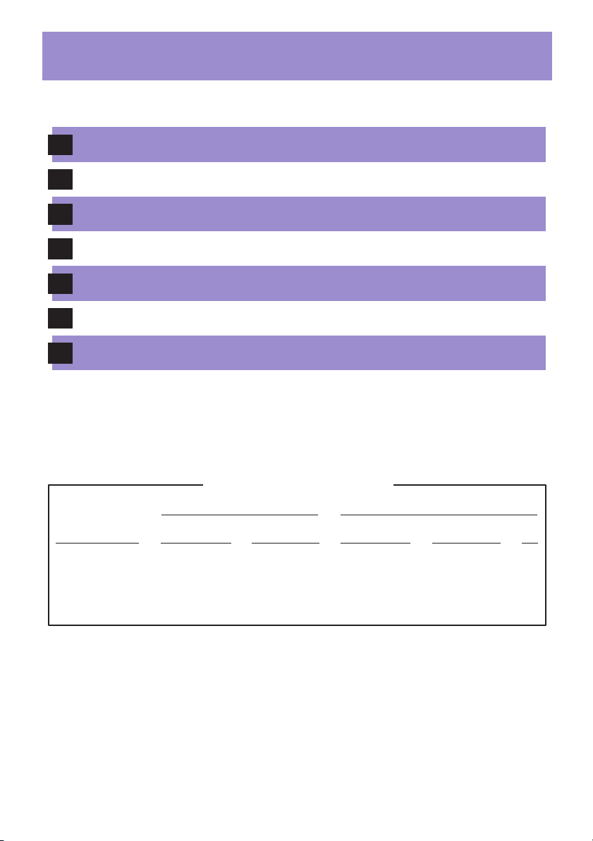
- Process and Specifications -
1
Verifying the Equipment
2
Installing the Hardware
3
Connecting the Cables
4
Configuring the UPS and the Ethernet Switch
5
Connecting the Laptop
6
Connecting to the G650 Media Gateway
7
Troubleshooting
Equipment
S8700 Servers
S8710 Servers
UPS
Ethernet switch
Hardware Specifications
English (lb)
23
60
>34
16.5
Metric (kg)
10.5
27
>15
7.5
DimensionsWeight
English (in)
3.5 x 17 x 17
3.4 x 26 x 17.5
3.5 x 17 x 19
3.5 x 17 x 18
Metric (cm)
9 x 43 x 43
8.6 x 66 x 45
9 x 43 x 48
9 x 43 x 46
Us
2
2
2
2
Page 10

- Legend -
D
o
c
u
m
e
n
t
a
t
i
o
n
Avaya technician
or business partner
Green
straight-through
CAT5 cable
Customer
network
Red
straight-through
CAT5 cable
2
Sequence step
Customer
Crossover
CAT5 cable
D
Duplex
reliability
Product
documentation
Services
laptop
H/C
High / Critical
reliability
Nonswitched
electrical outlet
Anti-static
wrist ground strap
required
System
administration
Filled-out Electronic
Pre-Installation
Worksheet (EPW)
Warning!
Use 2 people
to lift equipment
Page 11

Verifying the Equipment
1
0
/1
0
0b
T
ET
H
E
RNE
T
1
0
/
1
0
0b
T
ET
H
ER
NE
T
cable
(1 - 128)
IPSI adapter
Laptop to
server cable
CAT5
(1)
Modem cable
(2)
Services
laptop
UPS* (2)
Laptop to
server cable
CAT5
(1)
Modem cable
(2)
Services
laptop
(1)
(1)
19 in. (48.3 cm)
S8710 data rack
1
Product
documentation
CAT5
(1)
(4 - 68)
Fiber
cable
IPSI control network
Cross-point screwdriver
S8700 media server (2)
OR
5
5
4
4
COMPACT
disc
1
3
10
3
0
2
2
S8710 media server (2)
D
o
c
u
m
e
n
t
a
t
i
o
n
CAT5
cables
Hex-head wrench
(1/8 in., 3 mm)
(S8700 only)
2
1
1
2
UID
Duplexch ch
Simplex
PCMCIA
flashcard
(S8700)
FLASHDISK
Compact
flash
(S8710)
CAT5
(4 - 68)
(1)
Duplication
cable
IPSI adapter
0b
0b
0
0
1
/1
/
0
0
1
1
Ethernet switch* (1 or more)
Modem (2)
server cable
T
T
NE
RNE
E
ER
H
H
ET
ET
T
T
(1 - 128)
Screws
CAT5
(1)
Laptop to
Services
laptop
(2)
Modem cable
SNMP module
and cable
UPS* (2)
(2)
f
f
O
n
O
2
1
*Optional
Ethernet switch*
(1 or more)
UPS*
(2)
Customer network
Pre-Installation Worksheet
System administration
and filled-out Electronic
19 in. (48.3 cm)
S8700 data rack
(1)
Screws
19 in. (48.3 cm)
S8710 data rack
(1)
Page 12

Installing the Hardware: SNMP Module
2a
COMM PORT
ISOLATED
IOIOI
Off
On
1 2
D
TE
LA
PORT
ISO
M
AR
1
3
AL
RT
PO
IOI
COMM
IO
f
f
O
n
O
2
1
ALARM PORT
2
4
TED
RT
LA
ISO
M PO
AR
AL
PORT
I
MM
IO
CO
IO
f
f
O
n
O
2
1
NOTE: Your SNMP module may not look exactly like this.
Installing the Hardware: Mounting Brackets*
2b
U1 U21 2
8700
* For S8710, see 2C.
8
9
1
L
0
A
G
1
1
2
0
1
2
21
2
2
2
3
2
4
(Avaya P330 only)
Page 13

Installing the Hardware: Rail Installation to the Server
2c
(S8710)
5
5
4
4
3
3
2
2
C
O
d
M
P
A
C
i
T
s
c
1
10
0
2
1
1
1
2
2
Duplexch ch
U
U
I
I
D
D
Simplex
1
2
Page 14

2d
Installing the Hardware: Attaching Rails to the Rack (S8710)
Page 15

Installing the Hardware: Rack Installation (S8710)
2e
1
1
2
5
5
4
4
3
3
2
2
C
O
d
M
P
A
C
i
T
s
c
1
10
0
2
1
11
22
Duplexch ch
U
U
ID
ID
Simplex
Page 16

2f
Installing the Hardware: Rack Installation (S8700)
D
8
1 1
2 2
3 3
5'
(1.5 m)
4 5
6 7
2
1
1
* *
U1 U21 2
U1 U21 2
1 12
13 24
CONSOLE
2
5 6
1
7 8
Can be customer supplied
*
H/C
4
9
2
1
2
1
2
1
*
**
**
U1 U21 2
U1 U21 2
1 12
13 24
1 12
13 24
CONSOLE
CONSOLE
Page 17

Connecting the Cables: Duplex Reliability (S8700)
3a
D
(If dedicated
control network)
2
1
1
U1 U21 2
U1 U21 2
1
13
12
CONSOLE
24
1
0
1
0
5 4 3 2
TX RX
5 4 3 2
RX
TX
2
1
1
(If non-dedicated
control network)
Off
On
2
1
1 2
Off
On
1 2
2
1
Front
Rear
Page 18

Connecting the Cables: Duplex Reliability (S8710)
3b
(If dedicated
control network)
D
COMPACT
disc
5
5
2
4
4
5
5
1
4
4
3
3
2
2
3
3
2
2
1
1
10
0
COMPACT
disc
1
10
0
1
13
2
1
1
2
UID
Duplexch ch
Simplex
2
1
1
2
UID
Duplexch ch
Simplex
12
CONSOLE
24
3
2
3
2
3
100 MGz
MODE
RECEIVE
LINC
SYNC
TRANS
LINC
ACTIVE
MODE
DAL1
DUP
MEMORY
2
100 MGz
iLO
1
133 MGz
VDCI
3
100 MGz
MODE
SYNC
ACTIVE
RECEIVE
LINC
TRANS
LINC
MODE
DUP
MEMORY
DAL1
2
100 MGz
1
133 MGz
VDCI
2 1
UID
iLO
2 1
UID
2
1
1
(If non-dedicated
control network)
Off
On
2
1
1 2
Off
On
1 2
2
1
Front
Rear
Page 19

Connecting the Cables: High or Critical Reliability (S8700)
3c
H/C
(If dedicated
control network)
2
1
2
1
U1 U21 2
U1 U21 2
1
13
1
13
12
CONSOLE
24
12
CONSOLE
24
1
0
1
0
5 4 3 2
TX RX
5 4 3 2
RX
TX
2
1
2
1
(If non-dedicated
control network)
Off
On
2
1
1 2
Off
On
1 2
2
1
Front Rear
Page 20

Connecting the Cables: High or Critical Reliability (S8710)
3d
(If dedicated
control network)
H/C
COMPACT
disc
5
5
2
4
4
5
5
1
4
4
3
3
2
2
3
3
2
2
2
1
1
10
0
COMPACT
disc
1
10
0
1
13
1
13
2
1
1
2
UID
Duplexch ch
Simplex
2
1
1
2
UID
Duplexch ch
Simplex
12
CONSOLE
24
12
CONSOLE
24
3
2
3
2
3
100 MGz
SYNC
ACTIVE
RECEIVE
LINC
TRANS
LINC
MODE
MODE
MEMORY
DUP
DAL1
2
100 MGz
iLO
1
133 MGz
VDCI
3
100 MGz
RECEIVE
LINC
SYNC
TRANS
MODE
LINC
ACTIVE
MODE
MEMORY
DAL1
DUP
2
100 MGz
1
133 MGz
VDCI
2 1
UID
iLO
2 1
UID
2
1
2
1
(If non-dedicated
control network)
Off
On
2
1
1 2
Off
On
1 2
2
1
Front Rear
Page 21

3e
Configuring the Hardware: Duplication Cabling (S8700)
55554444333322
2
1
1
0
1
0
TX RX
2
RX
TX
22
1
55544433322
TX
RX
2
1
22
RX
TX
Page 22

2
3
VDCI
1
2
3
133 MGz
100 MGz
100 MGz
DAL1
DUP
MEMORY
RECEIVE
MODE
LINC
SYNC
TRANS
MODE
LINC
ACTIVE
2
3
VDCI
1
2
3
133 MGz
100 MGz
100 MGz
DAL1
DUP
MEMORY
RECEIVE
MODE
LINC
SYNC
TRANS
MODE
LINC
ACTIVE
3f
Configuring the Hardware: Duplication Cabling (S8710)
3
MODE
RECEIVE
TRANS
2
2
VDCI
1
3
RECEIVE
TRANS
MODE
2
1
VDCI
3
100 MGz
LINC
SYNC
LINC
ACTIVE
MODE
DAL1
DUP
MEMORY
2
100 MGz
1
133 MGz
iLO
2 1
UID
2
3
100 MGz
LINC
SYNC
LINC
ACTIVE
MODE
MEMORY
DAL1
DUP
2
100 MGz
1
133 MGz
iLO
2 1
UID
1
2
Page 23

4a
Configuring the UPS* and the Ethernet Switch
D
H/C
*If Avaya-supplied
2
1
2
1
2
1
1
Off
On
2
1 2
Off
On
1 2
1
1
2
Do
c
u
m
e
n
t
a
t
i
o
n
3
1
Page 24

4b
CONSOLE
CONSOLE
D
o
c
um
e
n
t
a
t
i
o
n
CONSOLE
CONSOLE
Configuring the UPS and the Ethernet Switch*
D
*If Avaya-supplied
2
1
1
2
1
2
1
2
1
2
1
1
Off
On
1 2
Off
On
1 2
2
1
2
1
H/C
U1 U21 2
U1 U21 2
1 12
13 24
CONSOLE
U1 U21 2
U1 U21 2
CONSOLE
3
2
D
o
c
um
e
n
t
a
t
i
o
n
4
2
1
1
Off
On
1 2
2
Off
On
1 2
1
2
1 12
13 24
1 12
13 24
CONSOLE
CONSOLE
CONSOLE
3
3
4
D
o
c
u
m
ent
a
t
ion
5
Page 25

5a
2
1
2
1
Connecting the Laptop (S8700)
D
2
H/C
2
1
1
2
1
1
1
Off
On
2
1
5b
Connecting to Laptop (S8700)
1 2
Off
On
1 2
D
H/C
2
1
2
1
2
1
2
D
3
o
cu
m
e
n
t
a
t
i
o
n
2
1
1
Off
On
2
1
1 2
Off
On
1 2
Page 26

5c
Connecting the Laptop (S8710)
D
3
3
100 MGz
MODE
RECEIVE
LINC
TRANS
LINC
MODE
SYNC
ACTIVE
MEMORY
DUP
DAL1
2
2
100 MGz
H/C
2
3
MODE
RECEIVE
2
iLO
2 1
1
133 MGz
VDCI
3
100 MGz
MODE
LINC
TRANS
LINC
SYNC
ACTIVE
DAL1
DUP
MEMORY
2
100 MGz
iLO
2 1
1
133 MGz
VDCI
1
Off
On
2
1
5d
Connecting to Laptop (S8710)
1 2
Off
On
1 2
D
3
3
100 MGz
MODE
MODE
RECEIVE
LINC
SYNC
TRANS
LINC
ACTIVE
DAL1
DUP
MEMORY
2
2
100 MGz
iLO
2 1
H/C
2
1
1
133 MGz
VDCI
3
3
100 MGz
SYNC
ACTIVE
RECEIVE
LINC
TRANS
LINC
MODE
MODE
MEMORY
DUP
DAL1
2
2
100 MGz
iLO
2 1
1
133 MGz
VDCI
2 1
UID
UID
2
D
3
o
c
u
m
e
n
t
a
t
i
o
n
1
2 1
UID
UID
2
1
1
Off
On
2
1
1 2
Off
On
1 2
Page 27

Connecting to the G650 Media Gateway
6
D
E
2
1
1
2
1
U1 U21 2
U1 U21 2
1 12
13 24
1
-48 VDC
-48 VDC
RETURN
CONSOLE
B
-48 VDC
-48 VDC
RETURN
A
-48 VDC
-48 VDC
RETURN
01
H/C
E
2
1
U1 U21 2
-48 VDC
-48 VDC
RETURN
U1 U21 2
IPSI adapter
2
1
1 12
13 24
1 12
13 24
CONSOLE
B
CONSOLE
01
2
-48 VDC
-48 VDC
RETURN
1
2
1
A
-48 VDC
-48 VDC
RETURN
01
Page 28

7
Troubleshooting
Problem: Solution:
Avaya equipment is missing
Contact the project manager
Customer equipment is missing
Customer network information is
missing
No power to the UPS
The a the
larm LEDs on UPS are
flashing
No power to
e
thernet switch
Alarm LEDs on the
ethernet
No power to the media server
The g the
reen status LED on server
is flashing slow
the Avaya-supplied
Avaya-supplied
switch are flashing
Contact the project manager
Contact the project manager
Is the UPS plugged into the outlet?
Does the outlet have power?
Refer to the UPS user's guide
Is the switch plugged into the UPS?
Does the UPS have power?
Refer to the Avaya-supplied ethernet
switch user's guide
Is the media server plugged into the
UPS?
Does the UPS have power?
Push the power button on the media
server to start
The server is in the standby mode
No V on IPSI LCD
the
Check the connection to the network
 Loading...