

Page 1

4600 Series IP Telephone
Release 2.2
Installation Guide
555-233-128
Issue 2.2
April 2005
Page 2

Copyright 2005, Avaya Inc.
All Rights Reserved
Notice
Every effort was made to ensure that the information in this document
was complete and accurate at the time of printing. However, information
is subject to change.
Warranty
Avaya Inc. provides a limited warranty on this product. Refer to your
sales agreement to establish the terms of the limited warranty. In
addition, Avaya’s standard warranty language as well as information
regarding support for this product, while under warranty, is available
through the following Web site: http://www.avaya.com/support
Trademarks
All trademarks identified by the ® or ™ are registered trademarks or
trademarks, respectively, of Avaya, Inc. All other trademarks are the
property of their respective owners.
Preventing Toll Fraud
“Toll fraud” is the unauthorized use of your telecommunications system
by an unaut horized pa rty (for exam ple, a person who is not a corporate
employee, agent, subcontractor, or is not working on your company's
behalf). Be aware that there may be a risk of toll fraud associated with
your system and that, if toll fraud occurs, it can result in substantial
additional charges for your telecommunications services.
Avaya Fraud Intervention
If you suspect that you are being victimized by toll fraud and you need
technical assistance or support, in the United States and Canada, call the
Technical Service Center's Toll Fraud Intervention Hotline at
1-800-643-2353.
Disclaimer
Avaya is not responsible for any modifications, additions or deletions to
the original published version of this documentation unless such
modifications, additions or deletions were performed by Avaya. Customer
and/or End User agree to indemnify and hold harmless Avaya, Avaya's
agents, servants and employees against all claims, lawsuits, demands
and judgments arising out of, or in connection with, subsequent
modifications, additions or deletions to this documentation to the extent
made by the Customer or End User.
How to Get Help
For additional support telephone numbers, go to the Avaya support Web
site: http://www.avaya.com/support
• Within the United States, click the Escalation Contacts link
that is located under the Support Tools heading. Then click
the appropriate link for the type of support you need.
• Outside the United States, click the Escalation Contacts link
that is located under the Support Tools heading. Then click
the International Services link that includes telephone
numbers for the international Cen ters of Excellence.
Providing Telecommunications Security
Telecommunications security (of voice, data, and/or video
communications) is the prevention of any type of intrusion to (that is,
either unauthorized or malicio us access to or use of) your company's
telecommunications equ ipm ent by some part y.
Your company's “telecommunications equipment” includes both this
Avaya product and any other voice/data/video equipment that could be
accessed via this Avaya product (that is, “networked equipment”).
An “outside party” is anyone who is not a corporate employee, agent,
subcontractor, or is not working on your company's behalf. Whereas, a
“malicious party” is anyone (including someone who may be otherwise
authorized) who accesses your telecommunications equipment with
either malicious or mischievous intent.
Such intrusions may be either to/through synchronous (time-multiplexed
and/or circuit-based) or asynchronous (character-, message-, or
packet- based) equipment or interfaces for reasons of:
• Utilization (of capabilities special to the accessed equipment)
• Theft (such as, of intellectual property, financial assets, or toll
facility access)
• Eavesdropping (privacy invasions to humans)
• Mischief (troubling, but apparently innocuous, tampering)
• Harm (such as harmful tampering, data loss or alteration,
regardless of motive or intent)
. If you are:
.
Be aware that there may be a risk of unauthorized intrusions associated
with your system and/or its networked equipment. Also realize that, if
such an intrusion should occur, it could result in a variety of losses to your
company (including but not limited to, human /da ta priva cy, intellectual
property, material assets, financial resources, labor costs, and/or legal
costs).
Responsibility for Your Company’s Telecommunications Security
The final responsibility for securing both this system and its networked
equipment rests with you - Avaya’s customer system administrator, your
telecommunications peers, and your managers. Base the fulfillment of
your responsibility on acquired knowledge and resources from a variety
of sources including but not limited to:
• Installation docume nts
• System administration documents
• Security documents
• Hardware-/software-based security tools
• Shared information between you and your peers
• Telecommunications security experts
To prevent intrusions to your telecommunications equipment, you and
your peers should carefully program and configure:
• Your Avaya-provided telecommunications systems and their
interfaces
• Your Avaya-provided software applications, as well as their
underlying hardware/software platforms and interfaces
• Any other equipment networked to your Avaya products
TCP/IP Facilities
Customers may ex perien ce dif fer ences i n prod uct p erforma nce, relia bili ty
and security depending upon network configurations/design and
topologies, even when the product performs as warranted.
Standards Compliance
Avaya Inc. is not responsible for any radio or television interference
caused by unauthorized modifications of this equipment or the
substitution or attachment of connec ting cab le s and equ ipme nt oth er
than those specified by Avaya Inc. The correction of interference caused
by such unauthorized modifications, substitution or attachment will be the
responsibility of the user. Pursuant to Part 15 of the Federal
Communications Commission (FCC) Rules, the user is cautioned that
changes or modifications not expressly approved by Avaya Inc. could
void the user’s authority to operate this equipment.
To order copies of this and other documents:
Call: Avaya Publications Center
Voice 1.800.457.1235 or 1.207.866.6701
FAX 1.800.457.1764 or 1.207.626.7269
Write: Globalware Solutions
200 Ward Hill Avenue
Haverhill, MA 01835 USA
Attention: Avaya Account Management
E-mail:totalware@gwsmail.com
For the most current versions of documentation, go to the Avaya support
Web site: http://www.avaya.com/support
.
Page 3

Contents
Chapter 1: Introduction . . . . . . . . . . . . . . . . . . . . . . . . . . . 5
About This Guide . . . . . . . . . . . . . . . . . . . . . . . . . . . . . . . . . . . 5
Intended Audience. . . . . . . . . . . . . . . . . . . . . . . . . . . . . . . . . . . 5
Document Organization . . . . . . . . . . . . . . . . . . . . . . . . . . . . . . . . 6
Change History . . . . . . . . . . . . . . . . . . . . . . . . . . . . . . . . . . 6
Terms Used in This Guide. . . . . . . . . . . . . . . . . . . . . . . . . . . . . 7
Conventions Used in This Guide . . . . . . . . . . . . . . . . . . . . . . . . . 8
Symbolic Conventions . . . . . . . . . . . . . . . . . . . . . . . . . . . . 8
Typographic Conventions. . . . . . . . . . . . . . . . . . . . . . . . . . . 8
Online Documentation. . . . . . . . . . . . . . . . . . . . . . . . . . . . . . . . . 8
Related Documents . . . . . . . . . . . . . . . . . . . . . . . . . . . . . . . . . . 9
Customer Support . . . . . . . . . . . . . . . . . . . . . . . . . . . . . . . . . . . 11
Chapter 2: 4600 Series IP Telephone Installation . . . . . . . . . . . . . 13
Introduction . . . . . . . . . . . . . . . . . . . . . . . . . . . . . . . . . . . . . . 13
IP Telephone Models . . . . . . . . . . . . . . . . . . . . . . . . . . . . . . . 14
Software . . . . . . . . . . . . . . . . . . . . . . . . . . . . . . . . . . . . . . 14
Pre-Instal lation Checklist . . . . . . . . . . . . . . . . . . . . . . . . . . . . . . . 15
Assembling the 4600 Series IP Telephone. . . . . . . . . . . . . . . . . . . . . . 18
Powering the 4600 IP Telephone . . . . . . . . . . . . . . . . . . . . . . . . . 18
Dynamic Addressing Process . . . . . . . . . . . . . . . . . . . . . . . . . . . . 27
Downgrading Avaya IP Te lephones . . . . . . . . . . . . . . . . . . . . . . . . . 31
Chapter 3: Local Administrative Options . . . . . . . . . . . . . . . . . 33
Introduction . . . . . . . . . . . . . . . . . . . . . . . . . . . . . . . . . . . . . . 33
Entering Data for Administrative Options . . . . . . . . . . . . . . . . . . . . . . 34
Entering Data for the 4601 IP Telephone . . . . . . . . . . . . . . . . . . . . . . . 36
About Local Administrative Procedure s. . . . . . . . . . . . . . . . . . . . . . . 37
Pre-Installation Checklist for St atic Addressing. . . . . . . . . . . . . . . . . . . 39
Static Addressing Installation. . . . . . . . . . . . . . . . . . . . . . . . . . . . . 39
QoS Option Setting . . . . . . . . . . . . . . . . . . . . . . . . . . . . . . . . . . 43
Interface Control . . . . . . . . . . . . . . . . . . . . . . . . . . . . . . . . . . . . 45
Group Identifier . . . . . . . . . . . . . . . . . . . . . . . . . . . . . . . . . . . . 48
Computer-Telephony Integration (CTI) Enable/Disable . . . . . . . . . . . . . . . 49
Site-Specific Option Number Setting . . . . . . . . . . . . . . . . . . . . . . . . . 50
Reset System Va lues . . . . . . . . . . . . . . . . . . . . . . . . . . . . . . . . . 51
Restart the Telephone . . . . . . . . . . . . . . . . . . . . . . . . . . . . . . . . . 53
Issue 2.2 April 2005 3
Page 4

Contents
Signaling Protocol Identifier . . . . . . . . . . . . . . . . . . . . . . . . . . . . . 54
Self-Test Procedure . . . . . . . . . . . . . . . . . . . . . . . . . . . . . . . . . . 56
Clear Procedure . . . . . . . . . . . . . . . . . . . . . . . . . . . . . . . . . . . . 57
Visual/Audible Al erting Procedure . . . . . . . . . . . . . . . . . . . . . . . . . . 58
Manually Setting the DHCP Client Hardware Address . . . . . . . . . . . . . . . 59
Setting L2Q Tagging Control (4601 Only) . . . . . . . . . . . . . . . . . . . . . . 61
Chapter 4: Troubleshooting Guidelines . . . . . . . . . . . . . . . . . . 63
Introduction . . . . . . . . . . . . . . . . . . . . . . . . . . . . . . . . . . . . . . 63
Error Conditions . . . . . . . . . . . . . . . . . . . . . . . . . . . . . . . . . . . . 63
DTMF Tones . . . . . . . . . . . . . . . . . . . . . . . . . . . . . . . . . . . . 64
Power Interruption . . . . . . . . . . . . . . . . . . . . . . . . . . . . . . . . . 64
The View Administrative Option . . . . . . . . . . . . . . . . . . . . . . . . . . . 65
Error and Status Messages . . . . . . . . . . . . . . . . . . . . . . . . . . . . . . 67
Troubleshooting the 4601 IP Telephone . . . . . . . . . . . . . . . . . . . . . . . 71
Appendix A: Restart Scenarios. . . . . . . . . . . . . . . . . . . . . . . 75
Scenarios for the Restart Process . . . . . . . . . . . . . . . . . . . . . . . . . . 75
Restart the Telephone. . . . . . . . . . . . . . . . . . . . . . . . . . . . . . . 75
Boot File Needs to be Upgraded . . . . . . . . . . . . . . . . . . . . . . . . . 76
Latest Boot File Loaded/No Application File or
Application File Needs to be Upgraded. . . . . . . . . . . . . . . . . . . . . 79
Latest Boot File and System-Specific
Application File Already Loaded . . . . . . . . . . . . . . . . . . . . . . . . 81
Index . . . . . . . . . . . . . . . . . . . . . . . . . . . . . . . . . . 85
4 4600 Series IP Telephone Release 2.2 Installation Guide
Page 5

Chapter 1: Introduction
Note:
!
About This Guide
This guide describes how to install the 4600 Series IP Telephone product line and troubleshoot
problems with the telephones.
The 4600 Series IP Telephone product line is a supplement to Avaya’s DEFINITY
MultiVantage™ IP Solutions platform.
®
/
Note: Unless otherwise indicated, references in this document to the DEFINITY
servers also refer to MultiVantage™ media servers.
Avaya SIP Telephone software, such as is in the 4602/4602SW SIP Telephones,
is not covered in this guide.
Intended Audience
This document is intended for personnel installing the 4600 Series IP Telephones.
CAUTION:
CAUTION: Avaya does not support many of the products mentioned in this document. Take
care to ensure that there is adequate technical support available for the servers
involved, including, but not necessaril y limited to, TFTP and DHCP servers. If t he
TFTP, DHCP, or other servers are not functioning correctly, the IP telephones
might not be able to operate correctly.
®
Issue 2.2 April 2005 5
Page 6

Introduction
Document Organization
The guide contains the following secti ons:
Chapter 1: Introduction Provides an overview of the 4600 Series IP Telephone
Installation Guide.
Chapter 2: 4600 Series IP
Telephone Installation
Chapter 3: Local
Administrative Options
Chapter 4: Troubleshooting
Guidelines
Appendix A: Restart
Scenarios
Change History
Issue 1.0 This document was issued for the first time in November 2000.
Issue 1.1 This version of the document, revised and issue d in April 2001, supports through
DEFINITY
Issue 1.5 This version of the document , re vis ed an d issued in J une, 2001, suppor ts t hroug h
DEFINITY
Describes the equipment and resources required to properly
install and operate the 4600 Series IP Telephones. Provides
instructions on installing the telephones out of the box.
Describes how to set local administrati ve options, if requested by
the system or LAN administrator.
Describes error conditions and messages that might occur
during the installati on of the 4600 Series IP Telephones.
Explains the different scen arios possi ble for the sequence of the
restart process.
®
Release 9.
®
Release 9.5.
Issue 1.6 This version of the document, revised and issued in December, 2001, supports
through DEFINITY
Telephone’s addition to the 4600 Series IP Telephone product line.
Issue 1.7 This version of the document, issued in July, 2002, supports through Avaya
Communication Manager Release 1.1. This version also supports the 4602 and
4620 IP Telephones’ addition to the 4600 Series IP Telephone product line.
Issue 1.8 This version of the document , re vis ed an d issued i n June, 2003, suppor t s t hroug h
Avaya Communication Manager Rel eases 1.2 and 1.3 . This vers ion als o support s
the 4602SW and 4630SW IP Telephones’ addition to the 4600 Series IP
Telephone product line.
6 4600 Series IP Telephone Release 2.2 Installation Guide
®
Release 10. This version also supports the 4630 IP
1 of 2
Page 7

Document Organization
Issue 2.0 This version of the document, revised and issue d in December, 2003, supports
through Avaya
Communication Manager Release 2.0. This version also supports
the addition of the 4610SW and 4620SW IP Telephones, and the 4690 IP
Conference Telephone to the 4600 Series IP Telephone product line.
Issue 2.1 This version of this document was revised and issued in July, 2004. This version
supports through Avaya
introduces the 4601 IP Telephone.
Issue 2.2 This is the current version of this document, revised and issued in April, 2005.
This version supports throug h Avaya Communication Manager Release 2.2. This
version also introduces the 4621SW, 4622SW, and 4625SW IP Telephones.
Terms Used in This Guide
802.1Q
802.1D
ARP Address Resolution Protocol, used to verify that the IP address provided by the
802.1Q defines a layer 2 frame structure that supports VLAN identification and a
QoS mechanism usually referred to as 802.1D.
DHCP server is not in use by another IP telephone.
Communication Manager Release 2.1. This version also
2 of 2
CLAN Control LAN, type of TN799 circuit pack.
DHCP Dynamic Host Configuration Protocol, an IETF protocol used to automate IP
address allocation and management.
DiffServ Differentiated Services, an IP-based QoS mechanism.
IETF Internet Engineering Task Force, the organization that produces standards for
communications on the internet.
LAN Local Area Network.
MAC Media Access Control, ID of an endpoint.
QoS Quality of Service, used to refer to several mechanisms inten ded to improve audio
quality over packet-based netwo rks.
RRQ Read Request packet. A message sent from the 4600 Series IP Telephone to the
TFTP server, requesting to download the upgrade script and the application file.
TCP/IP Transmission Contr ol Pro toco l/Inter net Protocol , a n etwor k-layer p rotocol used on
LANs and internets.
TFTP Trivial File Transfer Protocol, used to provide downloading of upgrade sc ripts and
application files to the IP telephones.
UDP User Datagram Protocol, a connectionless transport-layer protocol.
VLAN Virtual LAN.
Issue 2.2 April 2005 7
Page 8

Introduction
Note:
!
Conventions Used in This Guide
This guide uses the following textual, symbolic, and typographic conventions to help you
interpret informati on.
Symbolic Conventio ns
Note: This symbol precedes additional informat ion about a topic. This information is not
required to run your system.
CAUTION:
CAUTION: This symbol emphasizes possible harm to software, possible loss of data, or
possible service interrupt ions.
Typographic Conventions
This guide uses the following typographic conventions:
command Words printed in this ty pe are commands that you enter into your
system.
Message Words printed in this type are system messages.
device Words printed in this type indicat e p ara meter s associat ed with a
command for which you must substitute the appropriate value.
For example, when entering the mount command, device must
be replaced with the name of the drive that contains the
installation disk.
Administrative Words printed in bold type are menu or screen titles and labels.
Bold type words can also be items on menus o r screens that you
should select or enter to perform a task, i. e., fields, buttons, or
icons. Bold text is also used for general emphasis.
italics Italic type indicates a document that contains additional
information about a topic.
Online Documentation
The online documentation for the 4600 Series IP Telephones is located at the fol lowi ng URL :
http://www.avaya.com/support
8 4600 Series IP Telephone Release 2.2 Installation Guide
Page 9

Related Documents
● DEFINITY Documentation Release 8.4
This document describes how to administer a DEFINITY switch with Release 8.4
software.
● DEFINITY Documentation Release 9
This document describes how to administer a DEFINITY switch with Release 9 sof tware.
● DEFINITY Documentation Release 10
This document describes how to administer a DEFINITY switch with Release 10
software.
● Avaya Communication Manager Software Documentation Release 1.1
This document describes how to administer a switch with Avaya MultiVantage
(Release 1.1) software.
● Avaya Communication Manager Software Documentation Release 1.2
Related Documents
This document describes how to administer a switch with A vaya Communication
Manager (Release 1.2) soft ware.
● Avaya Communication Manager Software Documentation Release 1.3
This document describes how to administer a switch with A vaya Communication
Manager (Release 1.3) soft ware.
● Avaya Communication Manager Software Documentation Release 2.0
This document describes how to administer a switch with A vaya Communication
Manager (Release 2.0) soft ware.
● Avaya Communication Manager Software Documentation Release 2.1
This document describes how to administer a switch with A vaya Communication
Manager (Release 2.1) soft ware.
● Avaya Communication Manager Software Documentation Release 2.2
This document describes how to administer a switch with A vaya Communication
Manager (Release 2.2) soft ware.
● 4600 Series IP Telephone Safety Instructions
This document contains important user safety instructions for the 4600 Series IP
Telephones.
● 30A Switched Hub Set Up Quick Reference, Issue 2, July 2002 (Comcode 700234750)
This document contains import ant safety and installation information for the
30A Switched Hub.
Issue 2.2 April 2005 9
Page 10

Introduction
● 4600 Series IP Telephone LAN Administrator Guide
● 4601 IP Telephone User Guide
● 4602/4602SW IP Telephone User Guide
● 4606 IP Telephone User Guide
● 4610SW IP Telephone User Guide
This document describes how to administer DHCP, TFTP, and other servers as
appropriate for the 4600 Series IP Telephones. It also provid es troubleshooting
guidelines for the 4600 Series IP Telephones and for the DHCP and TFTP servers. The
LAN Administrator Guide contains information on how to administer advanced
applications for the 4610SW, 4620/4620SW/4621SW/4622SW/4625SW, and 4630/
4630SW IP Telephones.
This document provides detailed information about using the 4601 IP Telephone.
This document provides detailed infor m ation about using the 4602/4602SW IP
Telephone.
This document provides detailed information about using the 4606 IP Telephone.
This document provides detailed infor mation about using the 4610SW IP Telephone.
● 4612 IP Telephone User Guide
This document provides detailed information about using the 4612 IP Telephone.
● 4620/4620SW/4621SW IP Telephone User Guide
This document provides detailed infor mation about using the 4620/4620SW and
4621SW IP Telephones.
● 4622SW IP Telephone User Guide
This document provides detailed infor mation about using the 4622SW IP Telephone.
● 4624 IP Telephone User Guide
This document provides detailed information about using the 4624 IP Telephone.
● 4625SW IP Telephone User Guide
This document provides detailed infor mation about using the 4625SW IP Telephone.
● 4630/4630SW IP Telephone User Guide
This document provides detailed infor m ation about using the 4630/4630SW IP
Telephone.
● Avaya 4690 IP Conference Telephone User Guide
This document provides detailed information about using the 4690 IP Conference
Telephone.
10 4600 Series IP Telephone Release 2.2 Installation Guide
Page 11

Customer Support
● 4601/4602/4602SW IP Telephone Stand Instructions
This document provides information on how to desk- or wall-mount a
4601 or 4602/4602SW IP Telephone.
● 4610SW IP Telephone Stand Instructions
This document provides information on how to desk- or wall-mount a
4610SW IP Telephone.
● Wall Mount Instructions for the 4620/4620SW/4621SW IP Telephone
This document provides information on how to mount a 4620/4620SW/4621SW IP
Telephone on a wall.
● EU24/EU24BL Expansion Module User Guide
This document provides detailed infor mation about the EU24/EU24BL Expansion
Module. The EU24/EU24BL is an optional attachment that provides additional Feature
buttons for the 4620/4620SW, 4621SW, or 4622SW IP Telephones.
● EU24/EU24BL Installation and Safety Instructions
This document provides detailed installation instructions for the EU24/EU24BL
Expansion Module.
Customer Support
For 4600 Series IP Telephones’ support, call the Avaya support number prov ided to you by your
Avaya representative or Avaya reseller.
Information about Avaya products can be obtained at the following URL:
http://www.avaya.com/support
Issue 2.2 April 2005 11
Page 12

Introduction
12 4600 Series IP Telephone Release 2.2 Installation Guide
Page 13

Chapter 2: 4600 Series IP Telephone Installation
Introduction
The 4600 Series IP Telephone product line uses Int ernet Pr otoc ol (I P) t echnology with Ethernet
interfaces. The IP telephones supplement the existing DEFINITY
platform.
The 4600 Series IP Telephones support DHCP and TFTP over IPv4/UDP which enhance the
administration and servicing of the phones. These p hones use DHCP to obtain dynamic IP
addresses and TFTP or HTTP to download new software versions for the phones.
Most 4600 Series IP Telephones provide the ability to have one IP connection on the desktop
for both a telephone set and a PC. The 4606, 4612, 4624, and 4630 IP Telephones provide a
repeater. The 4602SW, 4610SW, 4620, 4620SW, 4621SW, 4622SW, 4625SW and 4630SW IP
Telephones, and the 30A switched hub, provide an Ethernet switch. The 4601 and 4602 IP
Telephones, and the 4690 IP Conference Telephone, have neither a repeater nor a switch, and
cannot share a port with a PC.
For information on Voice over IP, see the 4600 Series IP Telephone LAN Administrator Guide.
In compliance with Australian law, the following information is provided:
This equipment shall be installed and maint ain ed by trained serv ic e personnel. All the input /
output ports are classified as Safet y Extra Low Voltage (SELV, in the meaning of IEC
60950). To maintain safety compliance when connecting the equipment electrically to other
equipment, the interconnecting circuit s shal l be selected to prov ide cont inued confor mance
of clause 2.3 for SELV circuits (generally, double/reinforced insul ation to 24 0Vac rms to any
primary/mains circuitry and 120Vac rms to any telecommunications network circuit ry). To
ensure that these conditions are adhered to, interconnect the equipment only with the
already approved/certified equipment.
®
/MultiVantage™ IP Solutions
Issue 2.2 April 2005 13
Page 14

4600 Series IP Telephone Installation
IP Telephone Models
There are fifteen telephone set models defined in the 4600 Series IP Telephone family:
● 4601 IP
Telephone
● 4602 IP
Telephone
● 4602SW IP
Telephone
● 4606 IP
Telephone
● 4610SW IP
Telephone
● 4612 IP
Telephone
● 4620 IP
Telephone
● 4620SW IP
Telephone
● 4621SW IP
Telephone
● 4622SW IP
Telephone
● 4624 IP
Telephone
● 4625SW IP
Telephone
● 4630 IP
Telephone
● 4630SW IP
Telephone
● 4690 IP
Conference Telephone
Telephone models containing the SW designation have the same appearance, user inter face,
and functionality as their non-SW counterparts, with one exception. The phones have an
internal Ethernet swit ch that al lows th e te leph one and a PC to shar e the s ame LAN conn ecti on,
if appropriate. Thus, SW models do not need, or work wi th, the 30A swi tched hub interf ace. The
exception to this except ion is the 4620—bot h the 4620 and 4620SW co ntain an Et hernet switch.
Additionally, the 4630SW IP Telephone differs from the 4630 IP Telephone in two distinct ways.
The 4630SW can be LAN-powered and is FCC and CISPR Class B. The 4630 is a Class A
device that does not support LAN powering.
This document describes the install ation of these phones. For details about using th e features
provided by the phones, see the user documentation for each phone. For information about
desk or wall mounting any of the 4600 IP Telephone Series, see the instructions boxed wi th the
phone. Wall or desk mount inst ructions are also available on the Avaya support Web site.
Software
As shipped from the factory, the 4600 Series IP Telephones may not contain sufficient sof twar e
for registration and operati on. Wh en the phone is first plugged in, a software download from a
TFTP server is initiated. The soft ware download gives the phone the functionality of an Avaya
IP Telephone.
For downloads of software upgrades, the Avaya Media Server provides the capability for a
remote restart of the IP telephone . As a consequence of restarting, the phone automaticall y
restarts reboot procedures which result in a download if new software is available.
14 4600 Series IP Telephone Release 2.2 Installation Guide
Page 15

Pre-Installation Checklist
Before plugging in the 4600 Series IP Telephone, verify that all the following requirements are
met. Failure to do so prevents the telephone from working and can have a negative impact on
the network. Print copies of this checkli st for each server and IP telephone.
Requirements to Verify about the Network
1. The Avaya Media Server is adminis tered for IP telephones and has software for
Release 8.4 or later. Avaya Communication Manager Release 1.1 supports the
4602 and 4620/4620SW IP Telephones. The recommended configuration is the
latest PBX software and the latest IP telephone firmware. In the event you are
installing at a site without the latest PBX software, follow these recommendations:
Pre-Installation Checklist
Media Server
Release
Avaya
Communication
Manager 1.3+
Avaya
Communication
Manager 1.1,
Avaya
Communication
Manager 1.2
R10, Avaya
Communication
Manager 1.1,
Avaya
Communication
Manager 1.2
R10 4606, 4612,
R9.5 4606, 4612,
Avaya IP
Telephone
All
telephones
All
telephones
except 4630
4630 R1.74 Upgrade to Avaya
4624
4624
IP Telephone
Release Notes
R1.8+ Use the latest release.
R1.8+ Use the latest release.
Communication Manager
Release 1.3 or later before
installing R1.8 on 4630
Telephones.
R1.8+ The 4602 and 4620 are not
supported.
R1.8+ The 4620, 4602, and 4630
are not supported. R1.5 is
the minimum 4600 IP
Telephone vintage.
R9 4612, 4624 R1.1 R1.1 is the only supported
4600 IP Telephone vintage.
R8.4 4612, 4624 R1.0 R1.0 is the only supported
4600 IP Telephone vintage.
Issue 2.2 April 2005 15
Page 16

4600 Series IP Telephone Installation
!
Note:
Note:
CAUTION:
CAUTION: Using IP telephones on R8.4 or R9 requires extreme caution. You would be
downgrading the telephones to these very old releases. Downgrading any
Avaya IP Telephone other than the 4612 or 4624 to these old releases has not
been tested and might damage the telephone. See Downgrading Avaya IP
Telephones on page 31 for instructions on how to downgrade the software for
Avaya IP Telephones.
Note: The 4621SW and 4625SW can be aliased as a 4620 on any call server that
supports the 4620. In addition, Avaya Communication Manager Release 2.2
provides limited native support for the 4621SW and 4625SW. See the Avaya
Communication Manager Release 2.2 administration documentation for more
details.
Release 1.8 software changes the way the 4630 and 4630SW obtain
administered Feature button labels from the Media Server. Therefore, you must
have Avaya Communication Manager Release 1.2 for 4630 IP Telephone
Release 1.8 to work properly.
Requirements to Verify about the Network (continued)
2. The following two circuit packs are installed on the switch:
● TN2302 IP Media Processor circuit pack
● TN799B, C, or D Control-LAN (CLAN) circuit pack
3. The Avaya Media Server is configured correctly, as described in the documentation
listed in Related Documents
on page 9.
4. The DHCP server and application are administered as described in the 4600 Series
IP Telephone LAN Administrator Guide.
5. The TFTP or HTTP server and application are administered as desc ribed i n the 4600
Series IP Telephone LAN Administrator Guide.
6. The upgrade script and application files fro m the Avaya Support Web site ar e loaded
correctly on the TFTP server.
7. If applicable, the LDAP and DNS servers are administered as described in the 4600
Series IP Telephone LAN Administrator Guide. This is a consideration only for
4610SW/4620/4620SW/4621SW/4622SW/4625SW and 4630/4630SW installations.
8. If applicable, the Voice Mail and/or Web Messaging servers are administered as
described in the 4600 Series IP Telephone LAN Administrator Guide. This is a
consideration only for 4630/4630SW installations.
9. If applicable, the WML server is administered as described in the 4600 Series IP
Telephone LAN Administrator Guide. This is a consideration only for 4610SW and
4620/4620SW/4621SW/4622SW/4625SW installations.
Note: Any or all of the servers mentioned in items 4.-9. can be co-resident on the
same hardware.
16 4600 Series IP Telephone Release 2.2 Installation Guide
Page 17

Pre-Installation Checklist
Note:
Requirements to Verify for Each IP Telephone
10. You have an extension number and an Avaya Communication Manager security
code (password) for each IP telephone.
11. A Category 5e LAN jack is available at each phone site.
12. Electrical power is provided to each telephone by a Telephone Power Module (DC
power jack) (must be ordered separately). If the LAN will supply IEEE-standard
power to the 4601/4602/4602SW/4606/4610SW/4612/4620/4620SW/4621SW/
4622SW/4624/4625SW/4630SW, no power module is required.
Note: The 4630 IP Telephone does not support IEEE-standard power, and therefore
requires the Power Module.
The 4690 IP Conference Telephone is powered with a special LAN/power cable
with a power interface module included with this phone.
13. 1 Category 5e modular line cord is available for the connection between the IP
telephone and the PC.
14. Verify that the 4600 Series IP Telephone package includes the following
components:
● 1 telephone set
● 1 telephone handset, except the 4622SW and 4690 IP Conference
Telephones
● 1 H4DU 9-foot long (when extended) 4-conductor coiled handset cord,
plugged into the telephone and the handset, except the 4690 IP Conference
Telephone
● 1 Category 5 modular line cord for the connection from the IP telephone to
the Ethernet wall jack
● 4600 Series IP Telephone Safety Instructions (555-233-779)
● Power Brick for 4630 IP Telephones only
● Stylus for 4630/4630SW IP Telephones only
● Power Interface Module for the 4690 IP Conference Telephone only
Optional Items for Some IP Telephones
15. If applicable to your current installation, verify that the following equipment/
information is present:
● 30A Switched Hub (applicable to the 4612/4624/4630 only)
● Stand Instructions, packaged with certain IP Telephones
Issue 2.2 April 2005 17
Page 18

4600 Series IP Telephone Installation
!
Note:
!
Assembling the 4600 Series IP Telephone
CAUTION:
CAUTION: Be careful to use the correct jack when plugging in t he tel ephone. The jacks are
located on the back of the telephone housing and are flanked by icons to
represent their correct use.
Powering the 4600 IP Telephone
There are two options for powering t he 4601/4602/4602SW/4 606/4610SW/4612/ 4620/4620SW/
4621SW/4622SW/4624/4625SW/4630SW IP Telephones, and only one way to power the 4630
IP Telephone. All 4600 Series IP Telephones can be locally powered with a Telephone Power
Module (DC power jack), available separately. In addition, the 4601/4602/4602SW/4606/
4610SW/4612/4620/4620SW/4621SW/4622SW/4624/4625SW/4630SW IP Telephones support
IEEE 802.3af-standard LAN-based power. Before installing a 4601/4602/4602SW/4606/
4610SW/4612/4620/4620SW/4621SW/4622SW/4624/4625SW/4630 SW IP Telephone, verify
with the LAN administrator whether the LAN supports IEEE 802.3af, and if so, whether the
telephone should be powered locally or by means of the LAN.
The 4690 IP Conference Telephone is powered using a power interface module placed between
the LAN and the telephone on the Category 5 network cable.
Note: If your installation includes a 30A Switched Hub, follow the installation
instructions included in the Swit ched Hub box.
The last step in assembling the 4600 Series IP Telephone must be applying
power . Apply power either by plugging the power cord into the power source
(local powering) or plugging the modular li ne cord into the Ethernet wall jack
(IEEE powering).
CAUTION:
CAUTION: Failure to connect the proper cables with the proper jacks might result in an
outage in part of your network.
18 4600 Series IP Telephone Release 2.2 Installation Guide
Page 19

Assembling the 4600 Series IP Telephone
Figure 1 through Figure 6 provide illustrations to connect cords to jacks on 4600 IP Series
Telephones. See the chart below to determine the applicabl e illustration. Use the illustrations
and associated procedures as appropriate for telephone assembly.
Telephone Model: See:
4601
4602/4602SW
4606
4612
4624
4620/4620SW
Figure 1
Figure 1
Figure 1
Figure 1
Figure 1
Figure 2 or Figure 3
4621SW
4622SW
4625SW
4630/4630SW Figure 4
4610SW Figure 5
4690 Figure 6
Issue 2.2 April 2005 19
Page 20
4600 Series IP Telephone Installation
Figure 1: Connection Jacks on a 4601/4602/4602SW/4606/4612/4624 IP Telephone
DC
See Note
optional
=
facultatif
optionale
opcional
(DSS 4624)
20 4600 Series IP Telephone Release 2.2 Installation Guide
Page 21

Assembling the 4600 Series IP Telephone
Note:
1. Plug one end of the H4DU 4-conductor coiled handse t cord into the telephone and the ot her
end into the handset.
2. Plug one end of the first Category 5 modular line cord int o the Ethernet jack of the PC and g
the other end into the secondary Ethernet jack on the 4600 Series IP Telephone, if
appropriate.
Note: The 4602SW has PC and LAN jacks reversed from this picture. Ensure that you
make the right connections to the right equipment, as noted by the icons on the
telephone jacks.
3. Plug one end of the second Cat egory 5 modular li ne cord into t he Ethernet j ack on the 4600
Series IP Telephone. Plug the other end of this cord into the Ethernet wall jack. If the
telephone is to be IEEE-powered, you are finished. Do not proceed to Step 4.
4. If the telephone is to be powered locally in the United States and Canada, plug the
power cord into the 4600 Series IP Telephone, and the power cord plug int o the wall soc ket.
If the telephone is to be powered locally outside the United States and Canada,
connect the 1151 power brick to the power cable. Connect th e ot her e nd of the power cable
to the 4600 Series IP Telephone, and the plug to the wall socket.
Issue 2.2 April 2005 21
Page 22
4600 Series IP Telephone Installation
Note:
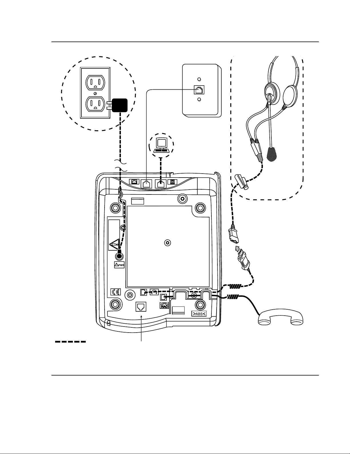
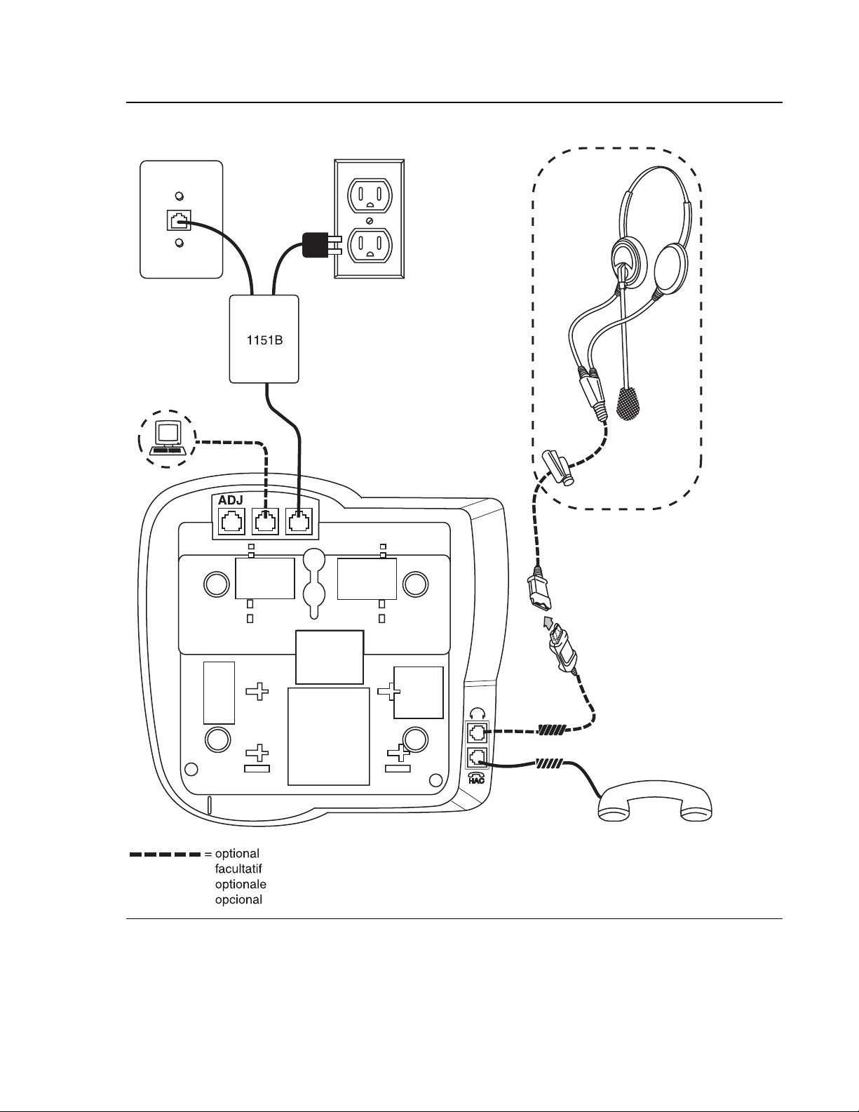
Figure 2: Connection Jacks on a 4620/4620SW/4621SW/4622SW/4625SW IP Telephone Option A
1151B
optional
=
facultatif
optionale
opcional
22 4600 Series IP Telephone Release 2.2 Installation Guide
Note: The 4622SW does not have a
handset, but instead can
support a second headset.
Page 23
Assembling the 4600 Series IP Telephone
Note:
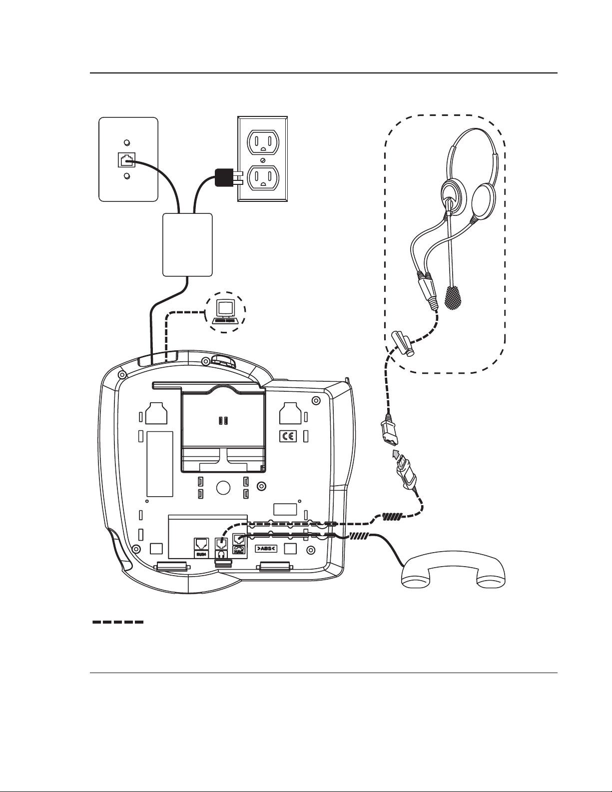
Figure 3: Connection Jacks on a 4620/4620SW/4621SW/4622SW/4625SW IP Telephone Option B
optional
=
facultatif
optionale
opcional
Note: The 4622SW does not have a
handset, but instead can
support a second headset.
Issue 2.2 April 2005 23
Page 24
4600 Series IP Telephone Installation
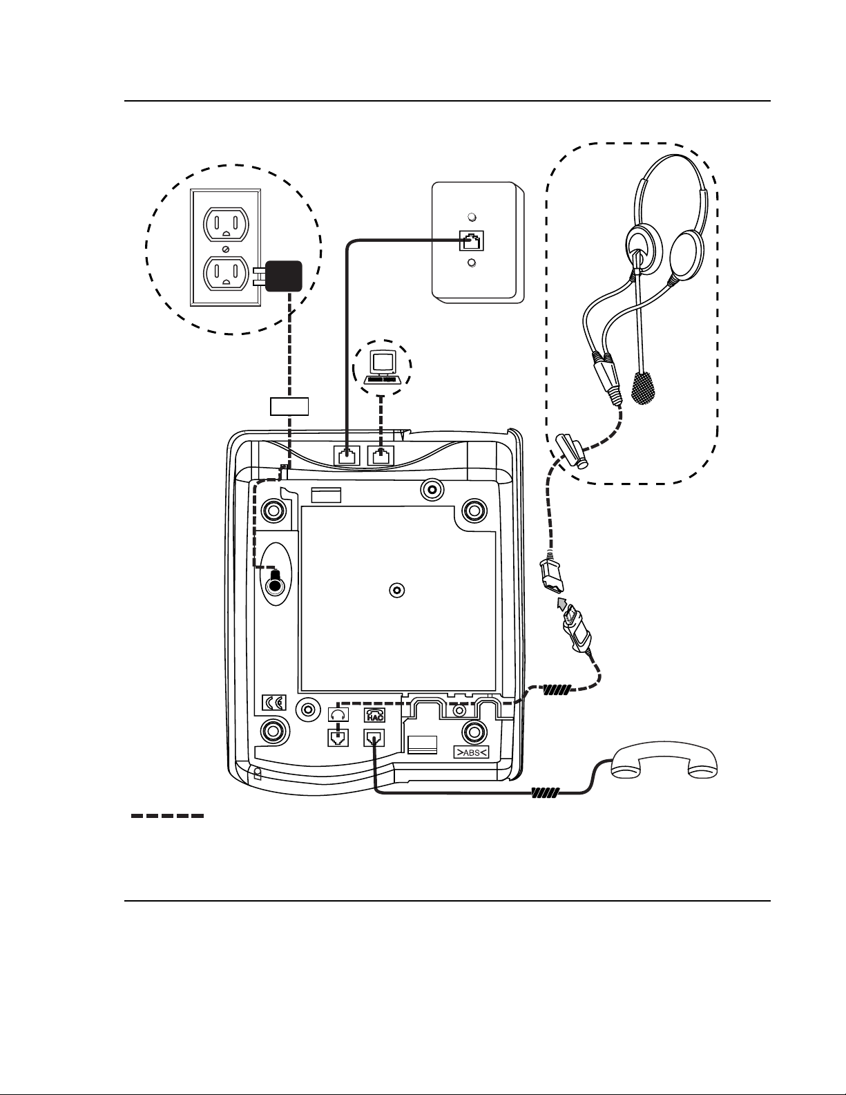
Figure 4: Connection Jacks on a 4630/4630SW IP Telephone
DC
optional
=
facultatif
optionale
opcional
24 4600 Series IP Telephone Release 2.2 Installation Guide
Page 25
Assembling the 4600 Series IP Telephone
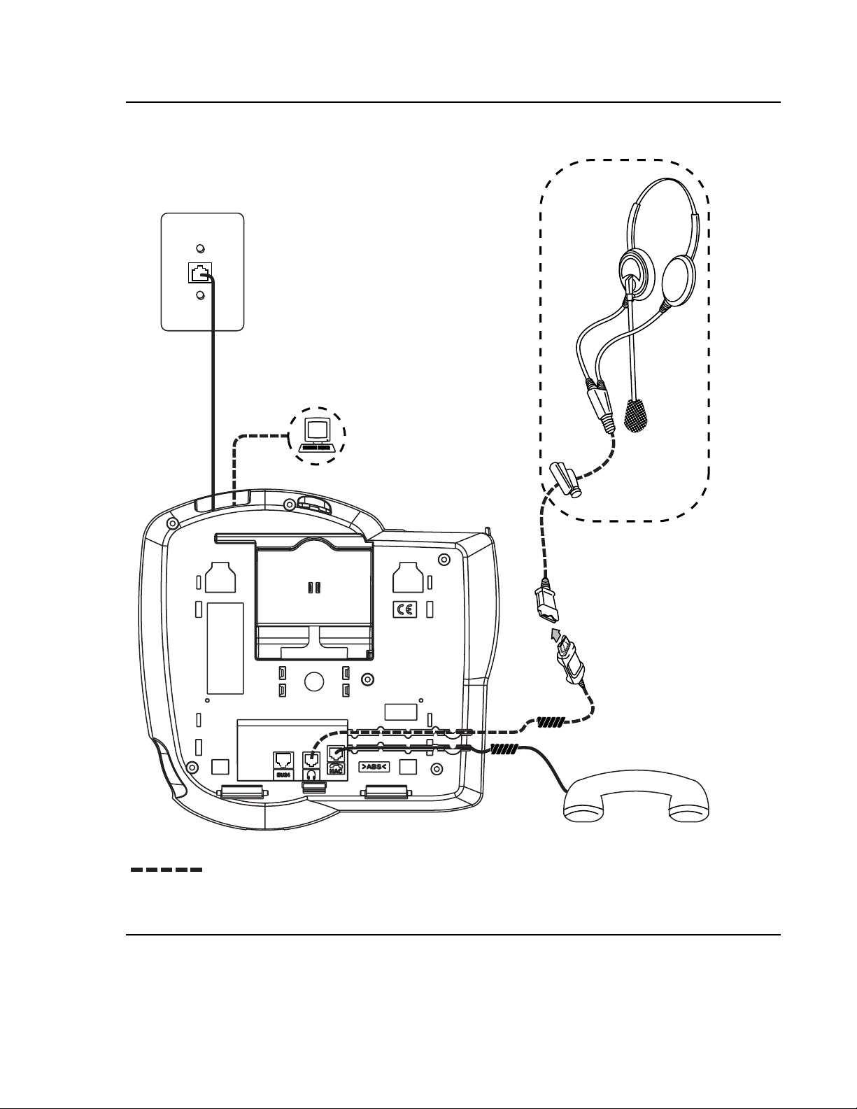
Figure 5: Connection Jacks on a 4610SW IP Telephone
Issue 2.2 April 2005 25
Page 26
4600 Series IP Telephone Installation
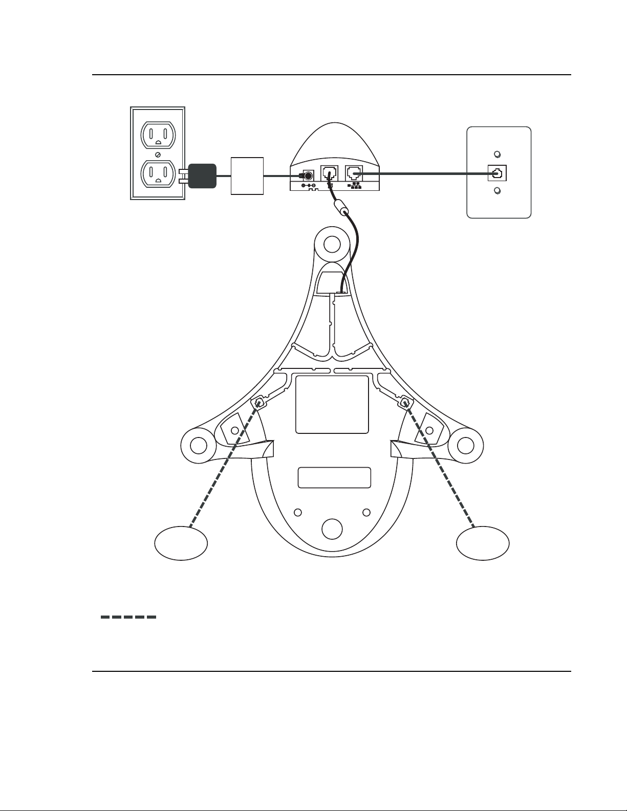
Figure 6: Connection Jacks on a 4690 IP Conference Telephone
DC
optional
=
facultatif
optionale
opcional
26 4600 Series IP Telephone Release 2.2 Installation Guide
Page 27

Dynamic Addressing Process
Note:
Note:
Note:
Note:
Note: Before starting this proc ess, you must have an extension number for the IP
telephone and the Avaya Communication Manager security code (password) for
that extension.
The following description of the process of installing the IP telephones assumes that the
process is executed successfully. Only an initial out of the box installation is described. For
errors that might be encountered duri ng the proc ess and the mes sages displ ayed, see Chapter
4: Troubleshooting Guidelines.
Note: Dynamic addressing is the only way to establ ish addressing parameters on the
4601 IP Telephone. Because the 4601 lacks a display, this phone uses its LEDs
to provide status indication. The instructions indicate processing exceptions or
elaborations specifically for 4601 IP Telephones where applicable.
When you plug the IP telephone set into the Ethernet wall jack and apply power, if applicable,
the following process takes place.
Dynamic Addressing Process
Note: If the application has already been downloaded, the whol e process takes
approximately 1 to 2 minutes after the phone is plugged in. For an initial
installation, incl uding the application download, the process might take 5 - 10
minutes. The duration is based on LAN loading, how many phones are being
installed at once, and simil a r factors.
Do not unplug the power cord during the download process.
1. The telephone activates the Ethernet l ine inte rface, the PC Ethernet jack, and di al pad i nput
to allow the invocation of procedures. The activat ion occurs as soon as possible after
power-up or a reset.
The telephone detects and displays the speed of the Ethernet interface in Mbps, that is, 10
or 100. The message No Ethernet displays until the softwar e determines whether the
interface is 10 Mbps or 100 Mbps.
For the 4601 only, all the 4601’s LED indicators illuminate to indicate system value
initialization. When system value init ialization completes, the 4601’s Call Appearance Line a
flashes continuously 500 milliseconds on, 500 milliseconds off while all other LEDs remain
lit.
Note: The Ethernet speed indicated is the LAN interfa ce speed for both the telephone
and any attached PC.
Issue 2.2 April 2005 27
Page 28

4600 Series IP Telephone Installation
2. The IP telephone sends a request to the DHCP server and invokes the DHCP process.
One of the following messages display:
DHCP: s secs
# to program
where s is the number of seconds that have elapsed since DHCP was invoked. The
message on the left appears if 802.1Q tagging is off and access to local programming
procedures is not disabled or restricted. (See Chapter 3: Local Administrative Options
specifics.) The middle message appears if 802.1Q taggi ng is on and access to local
programming procedures is disabl ed or r est rict ed. If t he lef t and middle messages alter nat e
every two seconds, 802.1Q tagging is on. When both messages alternate, access to local
programming procedures is not disabled or restricted. Finally, the message on the right
appears if 802.1Q tagging i s of f and access t o lo cal prog ramming procedures is d isabled o r
restricted.
3. The DHCP server provides IP addresses for the followi ng hardware:
● The IP telephone
● The TFTP or HTTP server
DHCP: s secs
VLAN ID = n
DHCP: s secs
for
● The TN799B, C, or D Control-LAN (CLAN) circuit pack on the media server
The 4601 cannot display messages. Therefore, if the DHCP process locates the required
information, the 4601’s Call Appearance Line b indicator flashes continuously 500
milliseconds on, 500 milliseconds off while all other LEDs remain lit. If the appropri ate
information cannot be discerned or is missing, the 4601’s Call Appearance Line a indicator
flutters 50 milliseconds on, 50 millise conds off three times while all other LEDs remain lit,
and a reset occurs.
4. Using the list of gateway IP addresses pr ovided by t he DHCP server, the phone performs a
router check. The phone cycles through the gateway IP addresses with ARPs or pings until
it receives a response. During this search, the 4601’s Call Appearance Line b indicator
flashes continuously 50 0 milliseconds on, 500 milli seconds off. All other 4601 LEDs remain
lit.
When the router is located, the TFTP or HTTP process star ts. If no router is found for a
4601 IP Telephone, its Call Appearance Line b flutters 50 milliseconds on, 50 milliseconds
off three times. All other 4601 LEDs remain lit, and a reset occurs.
28 4600 Series IP Telephone Release 2.2 Installation Guide
Page 29

Dynamic Addressing Process
5. The IP telephone connects to the TFTP or HTTP server and looks for an upgrade script file.
During TFTP or HTTP processing for the 4601 IP Telephone, both Call Appearance Line
indicators flash continuously 500 milliseconds on, 500 milliseconds off while all other LEDs
remain lit. If the appropriate info rmation cannot be discerned or is missing, both of the
4601’s Call Appearance Line indicators flutter 50 milliseconds on, 50 milliseconds off three
times. All other 4601 LEDs remain lit, and a reset occurs.
6. The TFTP or HTTP server sends and identifies an upgra de script.
The read request pac ket might hav e to be sent several times. Each ti me t he RRQ message
is sent, all IP telephones except the 4601 display one of the fol lowi ng me ssages:
TFTP: #
HTTP: n uri
www.xxx.yyy.zzz
For TFTP, # is the number of TFTP requests made by the phone and www.xxx.yyy.zzz
is the IP address of the current TFTP request. For HTTP, n is the number of HTTP request s
made by the phone and uri is the URI for the current HTTP request.
7. While the upgrade scrip t fi le is bein g downloaded, all IP t elephones except the 4601 di splay
the following message:
46xxUPGRADE.SCR
n KB received
where n is the number of KBs received from the TFTP server.
8. While the application file is downloaded to the IP telephone, all IP telephones except the
4601 display the following message:
filename
n KB received
where n is the number of KBs received from the TFTP server.
9. While the application file is saved in flash memory, all IP telephones except the 4601
display the following message:
Saving to flash
1%, 1 secs
with the percentage of the file and the number of elapsed seconds incremented as the
application file is stored in flash memory.
Issue 2.2 April 2005 29
Page 30

4600 Series IP Telephone Installation
10. The phone contacts the Avaya Media Server and attempts to log in.
All IP telephones except the 4601 display the foll owing prompt for an extension:
Extension=nnnnnn
#=OK NEW=_
The 4601 IP Telephone indicates the server is waiti ng fo r an e xtension entr y by fl ashing t he
Message Waiting Indicators 500 milliseconds on, 500 milliseconds of f. The Message
Waiting indicators are located at the top of the phone and the Message button LED on the
left middle of the faceplate.
11. Enter a new extension, ending with the # button. All telephones except the 4601 display
each digit entered, while the 4601 provide s LED and button- click feedback.
All IP telephones except the 4601 display the foll o wing prompt for a password:
Password=_
#=OK
12. Enter the password, endi ng with the # button. The 4601 provides LED and button-click
feedback for each digit upon entry.
Except for the 4601, the extension is visi ble as you enter it but the password displays as
asterisks. The 4601 just provides LED and button-click feedback for password entry.
13. The system determines whether the extension is in use.
14. Successful completion of this process produces the dial tone.
The IP telephone was installed successfully.
30 4600 Series IP Telephone Release 2.2 Installation Guide
Page 31

Downgrading Avaya IP Telephones
!
!
Important:
Important: We strongly recommend that you upgrade DEFINITY to the latest release rather
than take the extreme steps in th is section. There is no reason curr ently known to
downgrade any Avaya IP Telephone except to install a 4612 or 4624 IP
Telephone on a DEFINITY switch with a release prior to R9.5.
CAUTION:
CAUTION: Never attempt to downgrade an Avaya 4630 IP Telephone with a release earlier
than R1.8.
Create a TFTP server. Provide it with an IP address (IP_tftp) on the same sub-net as the IP
telephones you want to downgrade. Then:
1. Install the R1.1 sof twar e for DEFINI TY Releas e 9 or R1.0 for DEFINI TY Releas e 8.4 on the
TFTP server.
2. Manually assign the IP addresses for each 4612 or 4624, as indicated in Static Addressing
Installation on page 39 - including the FileSvr (IP_tftp).
Downgrading Avaya IP Telephones
3. Reboot the 4612 or 4624. The telephone downloads and inst alls the old boot code. This
results in the manual addresses of the IP telephones being erased.
4. Manually assign the IP addresses for each 4612 or 4624 including the FileSvr (IP_tftp).
5. Reboot the 4612 or 4624. The telephone will download and insta ll the R1.1 or R1.0 release .
6. Manually assign the IP addresses t o each 4612 or 4624. Assign 0.0.0.0 for the FileSvr . This
will prevent the telephones from upgradi ng until you are ready for them to upgrade.
7. REMOVE the old softwar e from the TFTP server. Removing the old software prevent s some
other Avaya IP Telephone from inappropriately downgrading.
Issue 2.2 April 2005 31
Page 32

4600 Series IP Telephone Installation
32 4600 Series IP Telephone Release 2.2 Installation Guide
Page 33

Chapter 3: Local Administrative Options
Note:
Introduction
After you have successfull y inst alle d an IP teleph one, you might be ins tructed to admi nister one
of the options described in this chapter.
Note: You can modify the settings file to set parameters for IP telephones that
download their upgrade script and application files from the same TFTP server.
See the section on “4600 Series IP Telephone Scripts and Application Files” in
Chapter 4 of the 4600 Series IP Telephone LAN Administrator Guide.
Because the 4601 IP Telephone does not have a display, it is limited in its ability
to support Local Administrative Procedures. Specifically, the only Local
Administrative Procedures the 4601 supports are:
● RESET (and Restart)
● SIG
● SSON
● TEST
● CHADDR (DHCP Client Hardware Address)
● ALERT
● TAG
In addition, because it lacks a display to provide visual feedback during data entry, the
4601 IP Telephone has unique data entry and feedback procedures. See Entering Data
for the 4601 IP Telephone on page 36.
Issue 2.2 April 2005 33
Page 34

Local Administrative Options
!
CAUTION:
CAUTION: Perform these procedures only if instructed to do so by the system or LAN
administrator.
Static administration of these options causes upgrades to work differently than if
they are administered dynamically. Values assigned to options in static
administration are not changed by upgrade scripts. These values remain active
for the telephone until either:
● a new boot file is downloaded, or
● the IP telephone is reset, as indicated in Reset System Values on page 51.
Aside from SSON, use these option-setting procedures only with static addressing
and, as always, only if instructed by the system or LAN administr ator. Aside from
SSON, do not use these option-setting procedures if you are using DHCP. DHCP is
the Dynamic Addressing Process, as indicated i n Dynamic Addres sing Process
page 27.
on
Entering Data for Administrative Options
This section applies to all IP telep hones with a display. It does not apply to the 4601 IP
Telephone, which does not have a display. This section describes how to enter data for
administrative options.
1. Invoke all local procedures by pressing the Hold or Mute button, up to 7 numeric dial pad
buttons, and the # button. The 4630/4630SW IP Telephones and the 4690 IP Conference
Telephone do not have a dedicated Hold button. On these phones, y ou mus t use t he Mute
button to access these options.
A 6-second timeout is in effect between button presses after pressing the Hold button. If
you do not press a valid button within 6 seconds of pressing the prev ious button, the
collected digits are discarded. In this case, no administrative option is invoked.
2. Attempts to enter invalid data are rejected, and the phone emits an error beep.
3. If you enter a numeric digit for a value or for an IP address or subnet mask field after
entering only a zero, the new digit replaces the zero .
4. Press the # button to go to the next step.
34 4600 Series IP Telephone Release 2.2 Installation Guide
Page 35

Entering Data for Administrative Options
Note:
5. How to backspace depends on the type of phone being installed, as shown in this chart:
IP Telephone # Backspace Alternative
4601 Call Appearance a button
4602 Speaker button
4602SW Speaker button
4606 Conference button
4610SW Left-most softkey
4612 Left-most softkey or Previous button
4620 Left-most softkey
4620SW Left-most softkey
4621SW Left-most softkey
4622SW Left-most softkey
4624 Left-most softkey or Previous button
4625SW Left-most softkey
4630 Headset button
4630SW Headset button
4690 Left-most softkey
When you press the applicable button or key to backsp ace, the most recently entered digit
or period is erased from the display. The cursor remains in the erased character’s former
position.
6. If PROCPSWD is administered as indicated in Chapter 4 of the 4600 Series IP Telephone
LAN Administrator Guide, you must type the Local Procedure password after pressing
Mute and before pressing the code for your given local programming option.
Note: If PROCSTAT has been administer ed to 1, as describe d i n Cha pter 4 of the 4600
Series IP Telephones LAN Administrator Guide, you will not be able to invok e any
administrative options other than V I E W.
Issue 2.2 April 2005 35
Page 36

Local Administrative Options
Entering Data for the 4601 IP Telephone
Because the 4601 IP Telephone has no display, its LEDs indicate:
● when data entry is required,
● whether processing is taking place, prohibiting data entry, and
● confirmation that a process or procedure is complete.
1. Invoke all local procedures by pressing the Hold button, up to 7 numeric dial pad buttons,
and the # button.
A 6-second timeout is in effect between button presses after pressing the Hold button. If
you do not press a valid button within 6 seconds of pressing the prev ious button, the
collected digits are discarded. In this case, no administrative option is invoked.
2. Attempts to enter invalid data are rejected, and the phone emits an error beep.
3. Press the # button to go to the next step.
4. To backspace within a field, press Call Appearance a’s Line button.
5. The following chart provides specific 4601 data entry/phone interaction information.
If Then
User input is expected/
required
The Message Wait ing indi cator at t he top of t he phone and the
Message button LED on the faceplate flash 500 milliseconds
on, 500 milliseconds off.
The telephone is
providing feedback
after an entry of one or
more numeric digits
from 1 to 9
Call Appearance Line a’s indicator winks 200 milliseconds on,
50 milliseconds off n times for digit n. For example, if you
press 2 as the first digit of a value like the SSON, Call
Appearance Line a’s indi cator winks two times.
For values having more than one digit with a second numeric
digit from 1 to 9, Call Appearance Line b’s indi cator wink s 200
milliseconds on, 50 milliseconds off n times for digit n. For
example, if you press 4 as the SSON’s second digit, Call
Appearance Line b’s indicator then winks four times.
Each subsequent digit of a specific value causes Call
Appearance Lines a and b to alternate winks.
The telephone is
providing feedback
after an entry of
Pressing 0 (zero) for a value causes the appropriate Call
Appearance Line indicator t o fl utter fi ve ti mes, 50 mill iseconds
on, 50 milliseconds off.
0 (zero)
1 of 2
36 4600 Series IP Telephone Release 2.2 Installation Guide
Page 37

If Then (continued)
About Local Administrative Procedures
In certain procedures,
for example, SSON or
to display the extension
number, a value al ready
exists and you press
the # button to indicate
you either want to enter
a new value or have the
current value displayed
User input is not
allowed for example,
during processing
The telephone’s boot
image is in the process
of being upgraded
An error beep tone
sounds
The Message Wait ing indi cator at t he top of t he phone and the
Message button’s LED on the faceplate are l it but not flashi ng.
Call Appearance Line a alternating with line b after an 1800
millisecond pause, if the value has more than one digit winks
600 milliseconds on, 200 milliseconds off n times for digit n to
indicate the current value. The appropriate Cal l Appearance
Line indicat o r flu tters five time s to in d i c a te th e di git zero. After
feedback of the current value, the Message Waiting indicator
at the top of the phone and the Message button’s LED flash
500 milliseconds on, 500 millis econds off t o indicate us er input
is expected/required.
The Message Wait ing indi cator at t he top of t he phone and the
Message button LED on the faceplate are steadily lit.
All LEDs, meaning Call Appearance Lines a and b, and both
Message indicators, light steadil y during the download
process.
An invalid button was pressed. Try again.
2 of 2
About Local Administrative Procedures
Local administrative procedures allow you to customize the 4600 Series IP Telephone
installation for your specific operating environment. This secti on provides a description of each
local administrative option covered in this guide, with references to the pages on which the
option appears.
Local Programming Option Code See
Static addressing A D D R (2 3 3 7) Static Addressing
Quality of Service options Q O S (7 6 7) QoS Option Setting on
PC Ethernet Interface I N T (4 6 8) Interface Control
Installation on page 39
page 43
on
page 45
1 of 2
Issue 2.2 April 2005 37
Page 38

Local Administrative Options
Local Programming Option Code See
Group Identifier
(Release 2.0 and later only)
Computer-Telephony
Integration
G R O U P (4 7 6 8 7) Group Identifier on
page 48
C T I (2 8 4) Computer-Telephony
Integration (CTI) Enable/
Disable on page 49
Site-Specific Option Number S S O N (7 7 6 6) Site-Specific Option
Number Setting on
page 50
Reset the telephone R E S E T (7 3 7 3 8) Res et System V alues
on
page 51
Restart the telephone R E S E T (7 3 7 3 8) Restart the
Telephone on page 53
Signaling protocol identif ier
(Release 2.0 and later only)
S I G (7 4 4) Signaling Protocol
Identifier on page 54
Test the telephone T E S T (8 3 7 8) Self-Test Procedure on
page 56
Clear values to factory defaults C L E A R (2 5 3 2 7) Clear Procedure
on
page 57
Visual Alerting mode control A L E R T (2 5 3 7 8) Visual/Audible Alerting
Procedure on page 58
DHCP chaddr field value C H A D D R (2 4 2 3 3 7) Manually Setting the
DHCP Client Hardware
Address on page 59
Layer 2 frame tagging control
(4601 only)
T A G (8 2 4) Setting L2Q Tagging
Control (4601 Only) on
page 61
2 of 2
38 4600 Series IP Telephone Release 2.2 Installation Guide
Page 39

Pre-Installation Checklist for Static Addressing
!
Pre-Installation Checklist for Static Addressing
Before performing static addressing, verify that all the requirements listed in the Requirements
to V erif y about the Network s ecti on of the Pr e-Installation Checklist are met. Y ou do not hav e to
consider item 4.
values for the following p arameters. Failure to do so can cause data entry errors that prevent
the telephone from working. Such errors can al so have a negative impa ct on your network. Pri nt
copies of this checklist for each subnet.
1. The IP address of the media server/gatekeeper.
2. The transport layer port number of the address of the Management Complex
3. The IP address of the gateway/router.
on page 16, as it refers to the DHCP server. In addition, you must have the
(media server/gatekeeper). Alt hough this can be a value between 0 and
65535, the default value is 1719. Do not change this value unless it conflicts
with an existing port assignment.
4. The IP netmask.
5. The IP address of the TFTP server.
Static Addressing Installation
The usual way to assign IP addresses to IP telephones is the automatic method described in
Dynamic Addressing Process
addresses is desired.
CAUTION:
CAUTION: Static addressing is necessary when a DHCP server is unavailable.
Because of the difficulties associated with static addressing, we very str ongly
recommend that a DHCP server be installed and static addr essing avoided.
. There might be times, however, when manual assignment of IP
Issue 2.2 April 2005 39
Page 40

Local Administrative Options
Note:
Note:
Note: The displays on the 4602, 4602SW, 4610SW, 4612, 4620, 4620SW, 4621SW,
4622SW, 4624, 4625SW , 4630, 4630SW , and 4690 IP Telephones accommodate
24 characters per line. The display on the 4606 Telephone accommodates 16
characters per line. Here and in the procedures that follow, the example on the
left shows the 4602, 4602SW, 4610SW, 4612, 4620, 4620SW, 4621SW,
4622SW, 4624, 4625SW, 4630, 4630SW, and 4690 Telephones’ display. The
example on the right shows the 4606 Telephone’s display. Showing only one
example means that example applies to all 4600 Series IP Telephones with
displays.
The 4601 IP Telephone does not support static addressing.
Use the following procedure to invoke manual address information programming.
1. Start manual address programming by performing one of the following steps:
a. During normal DHCP processing, press the * key while “* to program“ displays during
the DHCP process.
or
b. While the phone is on-hook and idle, press the following sequence of keys on the
faceplate of the telephone:
Mute 2 3 3 7 # (Mute A D D R #)
Note: Press the Mute button momentaril y. Do not press this button while pressi ng other
keys/buttons. The 4630/4630SW IP Telephones and the 4690 IP Conference
Telephone do not have a dedicated Hold button. For all other 4600 Series IP
Telephones, pressing the Hold button i nstead of the Mute button also works.
The following message displays:
Phone=nnn.nnn.nnn.nnn
New=_
or nnn.nnn.nnn.nnn
Phone=_
where nnn.nnn.nnn.nnn is the value of the telephone.
2. Enter the telephone’s IP address followed by the # button.
The following message displays:
CallSv=nnn.nnn.nnn.nnn
New=_
or nnn.nnn.nnn.nnn
CallSv=_
where nnn.nnn.nnn.nnn is the value of the media server/gatekeeper IP address.
40 4600 Series IP Telephone Release 2.2 Installation Guide
Page 41

Static Addressing Installation
3. Enter the Gatekeeper IP address followed by the # button.
The following message displays:
CallSvPort=nnnnn
New=_
where nnnnn is the value of the Management Complex (media server/gate keeper)
transport-layer port number, a value between 0 and 65535.
4. Enter the appropriate value for the Por t Number followed by the # button.
The following message displays:
Router=nnn.nnn.nnn.nnn
New=_
or nnn.nnn.nnn.nnn
Router=_
where nnn.nnn.nnn.nnn is the value of the gateway/router IP address.
5. Enter the Gateway router IP address followed by the # button.
The following message displays:
Mask=nnn.nnn.nnn.nnn
New=_
or nnn.nnn.nnn.nnn
Mask=_
where nnn.nnn.nnn.nnn is the value of the IP netmask.
6. Enter the IP netmask followed by the # button.
The following message displays:
FileSv=nnn.nnn.nnn.nnn
New=_
or nnn.nnn.nnn.nnn
FileSv=_
where nnn.nnn.nnn.nnn is the value of the TFTP server IP address.
7. Enter the TFTP Server IP address followed by the # button.
One of the following texts displays left-justified at the top of the display, depending on the
current status of 802.1Q:
If 802.1Q is off: 802.1Q=off
1=on #=OK
If 802.1Q is on: 802.1Q=on
0=off #=OK
8. Press the 1 or 0 button to turn 802.1Q on or off respectively.
The display is updated to show the current st atus of 802.1Q.
Issue 2.2 April 2005 41
Page 42

Local Administrative Options
9. Press the # button to continue the procedure without changing the displayed status of
802.1Q
The following text displays lef t-justified at the top of the display:
VLAN ID=dddd
New=_
where dddd is the value of the 802.1 VLAN ID.
10. Enter a valid value between 0 and 4094 for the new value of the 802.1 VLAN ID.
The following message displays:
VLAN test=ddd
New=_
where ddd is the value of the DHCPOFFER wait period.
11. Enter a valid value between 0 and 999 for the new value of the DHCPOFFER wait period.
The following message displays:
Save new
values?
*=no #=yes
12. Press the # button to save the new values you entered.
The following message displays:
New values
being saved
Once the new values are stored, the telephone is rese t.
If a new boot program is downloaded fr om the TFTP server af ter you enter static addressing
information, you must reenter your static addressing information.
42 4600 Series IP Telephone Release 2.2 Installation Guide
Page 43

QoS Option Setting
Note:
Note:
Use the following procedure to set Quality of Service (QoS) opti ons.
Note: The 4601 IP Telephone does not support QoS Option Setting.
1. While the phone is on-hook and idle, press the following sequence of keys on the faceplate
of the telephone:
Mute 7 6 7 # (Mute Q O S #)
Note: Press the Mute button momentaril y. Do not press this button while pressi ng other
keys/buttons. The 4630 and 4630SW IP Telephones and the 4690 IP Conference
Telephone do not have a dedicated Hold button. For all other 4600 Series IP
Telephones, pressing the Hold button i nstead of the Mute button also works.
The following text displays lef t-justified at the top of the display:
QoS Option Setting
L2 audio=d
New=_
where d is the value of the 802.1 audio parameter.
2. Enter a valid value between 0 and 7 for the new value of the 802.1 audio parameter.
The following text displays lef t-justified at the top of the display:
L2 signaling=d
New=_
where d is the value of the 802.1 signaling parameter.
3. Enter a valid value between 0 and 7 for the new value of the 802.1 signaling parameter.
The following text displays lef t-justified at the top of the display:
L3 audio=dd
New=_
where dd is the value of the Differential Services audio parameter .
Issue 2.2 April 2005 43
Page 44

Local Administrative Options
4. Enter a valid value between 0 and 63 for the new value of the Differential Services audio
parameter.
The following text displays lef t-justified at the top of the display:
L3 signaling=dd
New=_
where dd is the value of the Differential Services signali ng parameter.
5. Enter a valid value between 0 and 63 for the new value of the Differential Services
signaling parameter.
If no new values were entered during this procedur e, t he foll owing text di splays l ef t-jus tifi ed
at the top of the display:
No new values.
#=OK
6. Press # to terminate the procedure.
If new values were entered during this procedur e, the following text displays left- justified at
the top of the display:
Save new values?
*=no #=yes
7. Press the * button to terminate the procedure, or the # button to save the new values.
If you press the # button, the following text dis plays:
New values
being saved
The new values are saved, and the user interface is restored to i ts previous state.
44 4600 Series IP Telephone Release 2.2 Installation Guide
Page 45

Interface Control
Note:
Note:
Use the following procedure to set or change the interface control value.
Note: The 4601, 4602, and 4690 Telephones do not have Ethernet PC interfaces, so
this procedure does not apply to those phones.
1. While the phone is on-hook and idle, press the following sequence of keys on the faceplate
of the telephone:
Mute 4 6 8 # (Mute I N T #)
Note: Press the Mute button momentaril y. Do not press this button while pressi ng other
keys/buttons. The 4630 and 4630SW IP Telephones do not have a dedicated
Hold button. For all other 4600 Series IP Telephones, pressing the Hold but ton
instead of the Mute button also works.
2. For telephones that support an Infr ared (IR) interface (4620 and 4620SW only), proceed
directly to Step 7. If the telephones have an internal Ethernet switch, proceed to Step 3.
Interface Control
After entry of the command sequence, telephones with an internal Ethernet switch display
the following text, depending on the current interface control value:
PHY1=status
*=change #=OK
where status is the value of PHY1STAT, defined as:
● St atus is auto when PHY1STAT = 1
● St atus is 10Mbps HDX when PHY1STAT = 2
● St atus is 10Mbps FDX when PHY1STAT = 3
● St atus is 100Mbps HDX when PHY1STAT = 4
● St atus is 100Mbps FDX when PHY1STAT = 5
Issue 2.2 April 2005 45
Page 46

Local Administrative Options
3. To change the PHY1 value, press *.
Depending on the current value, the next sequenti al valid PHY1 value is selected and
displayed as the status. For example, if the current value is 10Mbps HDX (2), pressing *
changes the value to 3 (10Mbps FDX). If the current value is 100Mbps FDX (5), pressing *
changes the value to 1 (auto).
If a value different from the current PHY1STAT value is entered, the following text displ a ys
left-justified at the top of the display:
Save new
value?
*=no #=yes
4. Press the * button to terminate the procedure, or the # button to save the new value. If you
press the # button, the following text displ ays:
PHY2=status
*=change #=OK
where status is the value of PHY2STAT, defined as:
● St atus is disabled when PHY2STAT = 0
● St atus is auto when PHY2STAT = 1
● St atus is 10Mbps HDX when PHY2STAT = 2
● St atus is 10Mbps FDX when PHY2STAT = 3
● St atus is 100Mbps HDX when PHY2STAT = 4
● St atus is 100Mbps FDX when PHY2STAT = 5
5. To change the PHY2 value, press *.
Depending on the current value, the next sequenti al valid PHY2 value is selected and
displayed as the status. For example, if the current value is 10Mbps HDX (2), pressing *
changes the value to 3 (10Mbps FDX). If the current value is 100Mbps FDX (5), pressing *
changes the value to 0 (disabled).
The following text displays lef t-justified at the top of the display:
Save new value?
*=no #=yes
46 4600 Series IP Telephone Release 2.2 Installation Guide
Page 47

Interface Control
6. Press the * button to terminate the procedure, or the # button to save the new values.
If you press the # button, the following text dis plays.
New value
being saved
The new values are saved and a restart occurs automa tically. The user interface is restored
to its previous state.
7. For telephones with an IR interface, after entry of the command sequence, one of the
following texts displays, depending on the current value of the IRSTAT:
If IRSTAT=1: IR=enabled
0=disable #=OK
If IRSTAT=2: IR=disabled
1=enable #=OK
8. Press the 1 or 0 button to enable or disable the IR interface respectively, or press the #
button to leave the current value. The following text displays left-justified at the top of the
display:
Save new value?
*=no #=yes
9. Press the * button to terminate the procedure, or the # button to save the new values.
If you press the # button, the following text dis plays.
New value
being saved
The new values are saved, and a resta rt occurs auto matically. The user interface is restored
to its previous state.
Issue 2.2 April 2005 47
Page 48

Local Administrative Options
Note:
Note:
Group Identifier
Use the following procedure to set or change the Group Identifi er.
Note: Perform this procedure only if the LAN Administrator instructs you to do so.
The 4601 IP Telephone does not support the Group Identifier.
1. While the phone is on-hook and idle, press the following sequence of keys on the faceplate
of the telephone:
Mute 4 7 6 8 7 (Mute G R O U P)
Note: Press the Mute button momentaril y. Do not press this button while pressi ng other
keys/buttons. The 4630/4630SW IP Telephones and the 4690 IP Conference
Telephone do not have a dedicated Hold button. For all other 4600 Series IP
Telephones, pressing the Hold button i nstead of the Mute button also works.
The following text displays lef t-justified at the top of the display:
Group=ddd
New=_
where ddd is the Group value.
2. Enter a valid Group value (0-999).
If a value different from the current Group value is entered, the following text displays
left-justified at the top of the display:
Save new
value?
*=no #=yes
3. Press the * button to terminate the procedure, or the # button to save the new value.
If you press the # button, the following text displays:
New value
being saved
The new value is saved and the user interface is restored to its previous state.
48 4600 Series IP Telephone Release 2.2 Installation Guide
Page 49

Computer-Telephony Integration (CTI) Enable/Disable
Note:
Note:
Computer-Telephony Integration (CTI) Enable/Disable
Use the following procedure to enable or disable the CTI interface.
Note: The default for the CTI interface is enabled.
The 4601, 4602, 4602SW, and 4690 do not support the CTI interface.
1. While the phone is on-hook and idle, press the following sequence of keys on the faceplate
of the telephone:
Mute 2 8 4 # (Mute C T I #)
Note: Press the Mute button momentaril y. Do not press this button while pressi ng other
keys/buttons. The 4630/4630SW IP Telephones and the 4690 IP Conference
Telephone do not have a dedicated Hold button. For all other 4600 Series IP
Telephones, pressing the Hold button i nstead of the Mute button also works.
One of the following texts displays left-justified at the top of the display, depending on the
current value of the CTI:
If CTI=manual: CTI=manual
0=Off #=OK
If CTI=disabled: CTI=disabled
1=Manual #=OK
2. Press the 1 or 0 button to enable o r disab le the CTI i nte rface resp ectivel y, or the # button to
leave the current value. The following text displays left-justified at the top of the display:
UDP Port=497xx
New=_
where 497xx is the value of the UDP port for CTI.
3. Enter a valid value between 49714 and 49721, inclusive f or the UDP Port for CTI.
The following text displays lef t-justified at the top of the display:
Save new value?
*=no #=yes
Issue 2.2 April 2005 49
Page 50

Local Administrative Options
!
Note:
4. Press the * button to terminate the procedure, or the # button to save the new values.
If you press the # button, the following text dis plays.
New value
being saved
The new values are saved, and the user interface is restored to i ts previous state.
Site-Specific Option Number Setting
CAUTION:
CAUTION: Do not perform this procedure if you are using static addressing. Perform this
procedure only if you are using DHCP and the LAN administr ator instruct s you to
do this.
Use the following procedure to set the Site-Specific Option Number (SSON).
1. While the phone is on-hook and idle, press the following sequence of keys on the faceplate
of the telephone:
Mute 7 7 6 6 # (Mute S S O N #)
Note: Press the Mute button momentaril y. Do not press this button while pressi ng other
keys/buttons. The 4630/4630SW IP Telephones and the 4690 IP Conference
Telephone do not have a dedicated Hold button. For all other 4600 Series IP
Telephones, pressing the Hold button i nstead of the Mute button also works.
All IP telephones except the 4601 display the following text left-justified at the top of the
display:
SSON=ddd
New=_
where ddd is the value of SSON.
Because it does not have a display, the 4601 IP Telephone’s Call Appearance Line
indicators wink out the current SSON value. Call Appearance Lin e a represents the SSON’ s
first digit. Call Appearance Line b represents the SSON’s second digit, and Call
Appearance Line a represents t he SSON’s third digi t. For each di git, the appl icable in dicator
winks the number of ti mes represented b y the current SSON v alue 600 mil liseconds on, 200
milliseconds off. An 1800 millisecond pause occurs before changing indic ators. If the
current value is zero, the appropriate Call Appearance Line indicator flutters five times 50
milliseconds on, 50 milliseconds off instead of winking.
50 4600 Series IP Telephone Release 2.2 Installation Guide
Page 51

Reset System Values
!
After the 4601 “displ ays” the current SSON, the Message Waiting indicator at the top of the
phone and the Message button LED on the faceplate flash 500 milliseconds on, 500
milliseconds off to indicate an entry is expected.
2. Enter a valid value between 128 and 255 for the SSON.
The 4601 provides feedback as you enter each digit using both Call Appearance Line
indicators. The indicators alternat e winking the number of times represented by the digit you
press 200 milliseconds on, 50 milliseconds off. For example, if the SSON’s first di git is “2,”
pressing number 2 on the dial pad causes Call Appearance Line a’s indicator to wink two
times. If the second digit you press is “4,” af ter an 18 00 millisecond p ause, Call Appearan ce
Line b’s indicator winks four times. Pressing “0” (zero) on the dial pad causes the
appropriate indicator to flutter three five 50 milliseconds on, 50 milliseconds off.
Then the 4601 flashes both Message Wait ing indicators 500 milliseconds on, 500
milliseconds off to indicate an entry is expected.
For all IP telephones except the 4601, if a value different from the current SSON value is
entered, the following text displays left -justified at the top of the display:
Save new value?
*=no #=yes
3. Press the * button to terminate the procedure, or the # button to save the new value. If you
press the # button, all IP telephones except the 4601 display the following text:
New value
being saved
All phones save the new value, and restore the user interface to its previous state.
Reset System Values
Use the following procedure to reset all system initialization values to the application software
default values.
CAUTION:
CAUTION: This procedure erases all stat ic information, without any possibilit y of recovering
the data.
1. While the phone is on-hook and idle, press the following sequence of keys on the faceplate
of the telephone:
Mute 7 3 7 3 8 # (Mute R E S E T #)
Issue 2.2 April 2005 51
Page 52

Local Administrative Options
Note:
!
Note: Press the Mute button momentaril y. Do not press this button while pressi ng other
keys/buttons. The 4630/4630SW IP Telephones and the 4690 IP Conference
Telephone do not have a dedicated Hold button. For all other 4600 Series IP
Telephones, pressing the Hold button i nstead of the Mute button also works.
The 4601 IP Telephone flashes both Message Waiting indicators 500 milliseconds on, 500
milliseconds off to indicate user input is expected. All other IP telephones display the
following text left-justified at the top of the display:
Reset values?
*=no #=yes
CAUTION:
CAUTION: As soon as you press the # button, all static information will be erased, without
any possibility of recovering the data.
2. If you do not want to reset the system values, press * (no) and proceed to Step 4.
Pressing the pound sign (#) to reset the system values on a 4601 IP Telephone produces a
confirmation tone. The 4601’s Message Waiting indicators illuminate, but do not flash, to
indicate no entry is allowed while the system valu es are being reset. All other phones
display a screen with the following prompt on the top line:
Are you sure?
*=no #=yes
3. Press the * button to continue without resetting the values and proceed to Step 4. Or, press
the # button to reset values to their defaults.
All phones except the 4601 display the following text left-justified at the top of the display
while the system values are reset to defaults:
Resetting
values.
The telephone resets from the beginning of registration, which takes a few minutes.
4. If you do not reset the phone, all IP telephones except the 4601 display the following
prompt:
Restart
phone?
*=no #=yes
5. Press the * key to terminate the procedure without restarting the telephone. Otherwise,
press # and perform the following Restart procedure.
52 4600 Series IP Telephone Release 2.2 Installation Guide
Page 53

Restart the Telephone
Note:
Use the following procedure to restart the telephone.
1. While the phone is on-hook and idle, press the following sequence of keys on the faceplate
of the telephone:
Mute 7 3 7 3 8 # (Mute R E S E T #)
Note: Press the Mute button momentaril y. Do not press this button while pressi ng other
keys/buttons. The 4630/4630SW IP Telephones and the 4690 IP Conference
Telephone do not have a dedicated Hold button. For all other 4600 Series IP
Telephones, pressing the Hold button i nstead of the Mute button also works.
The 4601 IP Telephone flashes both Message Waiting Indicators 500 milliseconds on, 500
milliseconds off to indicate user input is expected. All other IP telephones display the
following text left-justified at the top of the display:
Reset values?
*=no #=yes
Restart the Telephone
2. Press the # button to reset values to their defaults, or * to continue a restart without
resetting the values to their defaults.
Pressing the pound sign (#) to reset the system values on a 4601 IP Telephone produces a
confirmation tone. The 4601’s Message Waiting indicators illuminate, but do not flash, to
indicate no entry is allowed while the system valu es are being reset. All other phones
display the following text left-justified at the top of the display while the system values are
reset to defa u lts:
Resetting
values.
Once the system values are reset, the followi ng prompt di splays on all IP telephones,
except the 4601:
Restart
phone?
*=no #=yes
3. Press the * key to terminate the procedure without restarting the telephone.
Press the # key to restart the telephone.
The remainder of the procedure depends on the status of the boot and appli cation files.
See Appendix A: Restart Scenarios
.
Issue 2.2 April 2005 53
Page 54

Local Administrative Options
Note:
Note:
Signaling Protocol Identifi er
Use the following procedure to set or change the Signaling Protocol Identifier. A valid SIG
Protocol Identifier is ei ther 0 (default), 1 (H.323), or 2 (SIP).
Note: Perform this procedure only if the LAN Administrator instructs you to do so.
1. While the phone is on-hook and idle, press the following sequence of keys on the faceplate
of the telephone:
Mute 7 4 4 (Mute S I G)
Note: Press the Mute button momentaril y. Do not press this button while pressi ng other
keys/buttons. The 4630/4630SW IP Telephones and the 4690 IP Conference
Telephone do not have a dedicated Hold button. For all other 4600 Series IP
Telephones, pressing the Hold button i nstead of the Mute button also works.
All IP telephones except the 4601 display the following text left-justified at the top of the
display:
SIG=protocol
*=change #=OK
where protocol is the telephone’s signaling protocol (H.323, SIP, or default) corresponding
to the numeric identifier (1, 2, or 0).
Because it does not have a display, the 4601 IP Telephone’s Call Appearance Line a’s
indicator winks out the current SIG value 600 milliseconds on, 200 milliseconds off. One
wink represents H.323 and two winks represent SIP. If the current value is zero (the
default), Call Appearance Line a’s indicator flutters five times 50 milliseconds on, 50
milliseconds off instead of winking. After the 4601 “displays” the current SIG value, the
Message Waiting indicator at the top of the phone and the Message button LED on the
faceplate flash 500 milliseconds on, 500 milliseconds off to indicate an entry is expected.
54 4600 Series IP Telephone Release 2.2 Installation Guide
Page 55

Signaling Protocol Identifier
2. To change the SIG value, press *.
Depending on the current value, the next sequential valid SIG value is selected and
displayed as the protocol. For example, if the cur rent value is SIP (2), pressing * changes
the value to 0 (default). If the current value is H.323 (1), pressing * changes the value to 2
(SIP).
If a value different from the current Group value is entered, all IP telepho nes except the
4601 display the following text left-justified at the top of the display:
Save new
value?
*=no #=yes
The 4601 IP Telephone instead flashes both Message Waiting indi cators 500 milliseconds
on, 500 milliseconds off to i ndicate an entry is expected.
3. Press the * button to terminate the procedure, or the # button to save the new value. If you
press the # button, all IP telephones except the 4601 display the following text:
New value
being saved
The new value is saved. All phones except the 4601 display the following text l eft-j ustified at
the top of the display:
Restart phone?
*=no #=yes
The 4601 IP Telephone instead flashes both Message Waiting indi cators 500 milliseconds
on, 500 milliseconds off to i ndicate an entry is expected.
4. Press the * (asterisk) key to terminate the procedure without restarting the telephone.
Press the # (pound) key to restart the telephone.
The remainder of this procedure depends on the status of the boot and application files.
See Appendix A: Restart Scenarios
.
Issue 2.2 April 2005 55
Page 56

Local Administrative Options
Note:
Self-Test Procedure
For self-testing, use the following procedure:
1. To invoke 4600 Series IP Telephone self-test procedures, press the following sequence of
keys on the faceplate of the telephone:
Mute 8 3 7 8 # (Mute T E S T #)
Note: Press the Mute button momentaril y. Do not press this button while pressi ng other
keys/buttons. The 4630 and 4630SW IP Telephones do not have a dedicated
Hold button. For all other 4600 Series IP Telephones, pressing the Hold but ton
instead of the Mute button also works. The 4690 IP Conference Telephone does
not support this feature.
For the 4606, 4612, and 4624 IP Telephones, the telephone ill uminates each column of red
and green LEDs associated with administrable buttons sequentially for 0.5 second, f rom left
to right across the telephone. This cycle then repeats. The S peaker/Mute LED and the
message waiting LED illuminate along with the closest column of LEDs. Buttons gener ate a
button click if press ed, but do not generate any system- specific signalin g messages, DTMF,
or invoke Speaker or Mute operation.
Telephones with displays show the following text, left-justifi ed at the top of the display, for 1
second after self-test is invoked:
Self test
#=end
For 4602/4602SW/4606/4610SW/4612/4620/4620SW/4624 IP Telephones, a block
character with all pixels on then displays in all display character locations for 5 seconds.
Display of the block character helps to find bad display pixels. For 4630 and 4630SW IP
Telephones, all pixels are on, and the display should be solid white for 5 seconds.
All IP telephones except the 4601 display one of the follo wing:
If self-test passes: Self test passed
#=end
When a 4601 IP Telephone’s self-test passes, all LEDs flash 500 milliseconds on, 500
milliseconds off continuously.
If self-test fails: Self test failed
#=end
When a 4601 IP Telephone’s self-test fails, all LEDs flutter 50 milliseconds on, 50
milliseconds off continuously.
2. To terminate the self-test, press the # butt on on the dial pad at any time. Doing so generates
a confirmation tone, and returns the user interface to its previous state.
56 4600 Series IP Telephone Release 2.2 Installation Guide
Page 57

Clear Procedure
!
Note:
Sometimes, you might want to remove all administered values, user-specified data, and option
settings. Essentially, you want to return a telephone to its initial “clean slate” condition.
This is usually done when passing a telephone to a new, dedicated user when the user’s
L O G O F F option is not suff icient. For example, a new user is assigned the same extension,
but requires different permissions than the previous user.
The C L E A R option erases all administered data—static programming, file server and call
server programming, and user settings including Speed Dial button labels and locally
programmed Feature button labels, and restor es all such data to default values. The C L E A R
option does not affect the software load itself. If you have upgraded the telephone, the phone
retains the latest software. Once you have cleared a telephone, you can administer it normally.
CAUTION:
CAUTION: This procedure erases all administe red dat a, without any possibilit y of recoveri ng
the data.
Use the following procedure to clear the phone of its administrative, user-assigned and options
values.
Clear Procedure
1. While the phone is on-hook and idle, press the following sequence of keys on the faceplate
of the telephone:
Mute 2 5 3 2 7 # (Mute C L E A R #)
Note: Press the Mute button momentaril y. Do not press this button while pressi ng other
keys/buttons. The 4630/4630SW IP Telephones and the 4690 IP Conference
Telephone do not have a dedicated Hold button. For all other 4600 Series IP
Telephones, pressing the Hold button i nstead of the Mute button also works.
The 4601 IP Telephone does not support the CLEAR procedure.
The following text displays lef t-justified at the top of the display:
Clear all values?
*=no #=yes
2. If you do not want to clear all values, press * (no) to terminate the procedure and retain the
current values.
A screen displays the following prompt on the top line:
Are you sure?
*=no #=yes
Issue 2.2 April 2005 57
Page 58

Local Administrative Options
Note:
3. Press the * button to terminate the procedur e without cleari ng the values. Press the # button
to clear all values to their initial default values.
A confirmation tone sounds and the following text displays left-justified at the top of the
display:
Clearing values.
The telephone is cleared to its “out o f the box” state.
Visual/Audible Alerting Procedure
Use this procedure to set or change the Alerting mode. As of software Release 2.2, all 4600
Series IP Telephones can alert a us er to incoming cal ls aud ibl y (t he de fault ) or both audibl y an d
visually. Visual alert is useful in noisy environments where an audible alert might not be heard,
or to tell at a glance which of several phones is ringing.
1. While the phone is on-hook and idle, press the following sequence of keys on the
telephone’s faceplate:
Mute 2 5 3 7 8 # (Mute A L E R T #)
Note: Press the Mute button momentaril y. Do not press this button while pressi ng other
keys/buttons. The 4630/4630SW IP Telephones and the 4690 IP Conference
Telephone do not have a dedicated Hold button. For all other 4600 Series IP
Telephones, pressing the Hold button i nstead of the Mute button also works.
All IP telephones except the 4601 display the following text left-justified at the top of the
display:
Alerting=setting
*=change #=OK
where setting corr esponds the current Alert value (NVALERT) as specified in “Chapter 4" of
the 4600 Series IP Telephone LAN Administrator Guide:
● Setting is audible-only when NVALERT = 0
● Setting is audible/visual when NVALERT = 1
Because it does not have a display, the 4601 IP Telephone’s Call Appearance Line a’s
indicator winks out the current NVALERT value 600 milliseconds on, 200 milliseconds off,
where one wink represents “0” for audible only and two winks represent “1” for audible/
visual. If the current value is zero (t he defaul t), Call Appearance Line a’s indicator flutters
five times 50 milliseconds on, 50 milliseconds off instead of winking. Afte r the 4601
“displays” the current NVALERT value, the Message Wait ing indicator at the top of the
58 4600 Series IP Telephone Release 2.2 Installation Guide
Page 59

Manually Setting the DHCP Client Hardware Address
Note:
phone and the Message button LED on the faceplate flash 500 milliseconds on, 500
milliseconds off to indicate an entry is expected.
2. To change the Alerting value, press *.
Depending on the current value, the other value is selected and displayed. For example, if
the current value is audible/visual (1), pressing * changes the value to 0 (audible only, the
default). If the current value is audible-only (0), pressing * changes the value to 1 (audible/
visual).
All IP telephones except the 4601 display the following text left-justified at the top of the
display:
Save new value?
*=no #=yes
The 4601 IP Telephone instead flashes both Message Waiting indi cators 500 milliseconds
on, 500 milliseconds off to i ndicate an entry is expected.
3. Press the * button to terminate the procedure, or the # button to save the new value. If you
press the # button, all IP telephones except the 4601 display the following text:
New value being saved
The new value is saved.
Manually Setting the DHCP Client Hardware Address
Use this procedure to manually set or change the Client Hardware Address, if you use static
addressing rather than DHCP.
1. While the phone is on-hook and idle, press the following sequence of keys on the
telephone’s faceplate:
Mute 2 4 2 3 3 7 # (Mute C H A D D R #)
Note: Press the Mute button momentaril y. Do not press this button while pressi ng other
keys/buttons. The 4630/4630SW IP Telephones and the 4690 IP Conference
Telephone do not have a dedicated Hold button. For all other 4600 Series IP
Telephones, pressing the Hold button i nstead of the Mute button also works.
Issue 2.2 April 2005 59
Page 60

Local Administrative Options
All IP telephones except the 4601 display the following text left-justified at the top of the
display:
chaddr=ddd
New=
where ddd is the value of NVCHADDR, the system variable for the DHCP Client Hardware
Address.
Because it does not have a display, the 4601 IP Telephone’s Call Appearance Line a’s
indicator winks out the cur rent NVCHADDR value 600 milliseco nds on, 200 milli seconds of f.
If the current value is zero, Call Appearance Lin e a’s indicator flutters five times 50
milliseconds on, 50 milliseconds off instead of winking.
After the 4601 “displays” the current value, the Message Waiting indicator at the top of the
phone and the Message button LED on the faceplate flash 500 milliseconds on, 500
milliseconds off to indicate an entry is expected.
2. To change the Client Hardware Address value, enter a valid client hardware address. This
value is usually the MAC address, which DHCP then convert s to an integer preceded by
zeroes.
The 4601 provides feedback for each digit as you enter it using both Call Appearance Line
indicators. The indicators alternat e winking the number of times represented by the digit you
press 200 milliseconds on, 50 mi lliseconds of f. For exampl e, if the f irst digit of the address i s
“2,” pressing the number 2 on the dial pad causes Call Appearance Line a’s indicator to
wink two times. If the second digit you press is “4,” after an 1800 millisecond pause, Call
Appearance Line b’s indicator winks four times. Pressing “0” (zero) on the dial pad causes
the appropriate indicator to fl utter three five 50 milliseconds on, 50 milliseconds off.
Then the 4601 flashes both Message Wait ing indicators 500 milliseconds on, 500
milliseconds off to indicate an entry is expected.
For all IP telephones except the 4601, if a value different from the current value of
NVCHADDR is entered, the following text displays left-justified at the top of the display:
Save new value?
*=no #=yes
3. Press the * button to terminate the procedure, or the # button to save the new value. If you
press the # button, all IP telephones except the 4601 display the following text:
New value being saved
All phones save the new value.
60 4600 Series IP Telephone Release 2.2 Installation Guide
Page 61

Setting L2Q Tagging Control (4601 Only)
Note:
Setting L2Q Tagging Control (4601 Only)
Use the following procedure to set the layer 2 (802.1Q) framing parameter manually for the
4601 IP Telephone only.
1. While the phone is on-hook and idle, press the following sequence of keys on the faceplate
of the telephone:
Mute 8 2 4 # (Mute T A G #)
Note: Press the Mute button momentaril y. Do not press this button while pressi ng other
keys/buttons. Pressing the Hold button instead of the Mute button also works.
Because it does not have a display, the 4601 IP Telephone’s Call Appearance Line
indicators wink out the current NVL2Q value. Valid values are:
● 1=ON (enabled)
● 2=OFF (disabled)
● 3-AUTO (the default)
The single-digit value is represent ed by Call Appearance Line a, which winks the number of
times represented by the current L2Q value 600 mil liseconds on, 200 milli seconds of f. If the
current value is zero (AUTO), Call Appearance Line a’s indicator flutters five times 50
milliseconds on, 50 milliseconds off instead of winking.
After “displaying” the current L2Q value, the Message Waiting indicator at the top of the
phone and the Message button LED on the faceplate flash 500 milliseconds on, 500
milliseconds off to indicate an entry is expected.
2. Enter a valid value (1, 2, or 0) for the L2Q (802.1Q) framing parameter.
The 4601 provides feedback for the digit as you enter it using Call Appearance Line a. For
example, if the L2Q value is “2,” pressing the number 2 on the dial pad causes Call
Appearance Line a’s indicator to wink two times. Pressing “0” (zero) on the dial pad cause s
Call Appearance Line a’ s indicator to flutter three times 50 milliseconds on, 50 milliseconds
off.
Then both Message Waiting indicators flash 500 milliseconds on, 500 milliseconds off to
indicate an entry is expected.
3. Press the * button to terminate the procedure, or the # button to save the new value. If you
press the # button, the 4601 saves the new value, and resets the telephone to restore the
user interface to its previous state.
Issue 2.2 April 2005 61
Page 62

Local Administrative Options
62 4600 Series IP Telephone Release 2.2 Installation Guide
Page 63

Chapter 4: Troubleshooting Guidelines
Introduction
This chapter describes problems that might occur during installation of the 4600 Series IP
Telephones and possible ways of resolving these problems. For problems that occur during
normal operation, see “Troubleshooting Guidelines” in the 4600 Series IP Telephone LAN
Administra t o r G u id e .
This chapter contains the following sections:
● Descriptions of error conditi ons and me thods for resolving them.
● The use of the V I E W option to view system values.
● Error and status messages, and methods for resolvi ng them.
Error Conditions
There are four areas where installers can troubleshoot problems before seeking assistance
from the system or LAN administrator:
1. Check both the power and Ethernet wiring for the following conditions:
● Whether all components are plugged in correctly.
● Check LAN connectivity in both directions to all servers - DHCP, TFTP, HTTP,
DEFINITY
● If the telephone is supposed to be powered from the LAN, ensure that the LAN is
properly administered and is compliant with IEEE 803.3af.
● Ensure that the Ethernet complies with Category 5e wiri ng.
2. If you are using static addr essing:
● Use the View command) to find the names of the files being used and verify that these
filenames match those on the TFTP or HTTP server. See The View Administrative
Option on page 65 for more information. Check the Avaya Web site to verify whether the
correct files are being used.
®
/MultiVantage™.
Issue 2.2 April 2005 63
Page 64

Troubleshooting Guidelines
Note:
● Use the ADDR option to verify IP addresses. See Static Addressing Installation on
page 39 for information.
● Use the QoS option to verify QoS parameters.
See Chapter 3: Local Administrative Options
3. If the 4600 Ser ies IP Telephone is not communicating with the system (DHCP, TFTP, HTTP
or Avaya Media Server), make a note of the last message displayed. Consult the system
administrator.
4. If you expect the telephone to be IEEE-powe red, verify with the LAN administra tor that IEEE
power is indeed supported on the LAN.
Note: Because the 4601 IP Telephone does not have a display, it is limited in its ability
to provide visual feedback and err or messages. See T roublesh ooting the 4601 IP
Telephone later in this chapter for more information.
DTMF Tones
The failure to hear DTMF tones sent by a far-end 4600 Series IP Telephone does not require
any action on the user’s part. The TN2302AP board does not pass in-band DTMF tones.
Power Interruption
.
If power to a 4600 Series IP Telephone is interrupted while the telephone is saving the
application file, the TFTP application can stop responding. If this occurs, restart the TFTP
server.
64 4600 Series IP Telephone Release 2.2 Installation Guide
Page 65

The View Administrative Option
Note:
Note:
If you are using st atic addr essing and encounter pr oblems, use t he following pr ocedure to verif y
the current values of system parameters and file versions.
Note: Also use the ADDR option to view IP addresses. See Static Addressing
Installation in Chapter 3: Local Administrative Options. The IP addresses might
have been entered incorrectly. Verify whether you were provided with correct IP
addresses.
The 4601 IP Telephone does not support the V I E W option.
1. While the phone is on-hook and idle, press the following sequence of keys on the faceplate
of the telephone:
Mute 8 4 3 9 # (Mute V I E W #)
The View Administrative Option
Note: Press the Mute button momentarily. Do not press this key while pressing other
keys. The 4630/4630SW IP Telephones and the 4690 IP Conference Telephone
do not have a dedicated Hold button. For all other 4600 Series IP Telephones,
pressing the Hold button instead of the Mute button also works.
The following text displays lef t-justified at the top of the display:
View settings
*=next #=exit
2. Press the * button at any time during viewing to display the next name and system value
pair from Table 1
. The first pair retur ns a fter the last pair dis plays.
Press the # button at any time during viewing to terminate the procedure and restore the
user interface to its previous state. The names and values display in the following order:
Table 1: Parameter Values
Name System Value Format
Model 46ccDccc Up to 8 ASCII graphics characters.
Market domestic
Only one value displays.
export
Phone SN cccccccccccc
cccccccc
Phone Serial Number , up to 1 8 ASCII
graphic characters.
1 of 2
Issue 2.2 April 2005 65
Page 66

Troubleshooting Guidelines
Table 1: Parameter Values (continued)
Name System Value Format
PWB SN cccccccccccc
cccccccc
Printed Wiring Board (circuit board)
Serial Number, up to 18 ASCII
graphic characters.
PWB
ccccccccc 9 ASCII numbered characters.
comcode
MAC
address
00:60:1D:hh:hh:hh Each octet of the MAC address
displays as a pair of hexadecimal
numbers.
L2 tagging ccccccccc Up to 9 ASCII characters.
VLAN ID cccc Up to 4 ASCII charac ters. Value is ID
number or “none.”
IP address nnn.nnn.nnn.nnn Up to 15 ASCII characters.
Subnet mask nnn.nnn.nnn.nnn Up to 15 ASCII characters.
Router nnn.nnn.nnn.nnn Up to 15 ASCII characters.
File server nnn.nnn.nnn.nnn.nnnnn Up to 21 ASCII characters: IP
address and port of last file server
used successfully.
Media server nnn.nnn.nnn.nnn.nnnnn Up to 21 ASCII characters: IP
address and port of media server
currently in use.
Group nnn Up to 3 ASCII characters.
Protocol cccccccc
filename1.exe
filename2.exe
66 4600 Series IP Telephone Release 2.2 Installation Guide
Up to 8 ASCII characters.
Up to 16 ASCII graphic characters.
Out of the box, there is only one
filename.exe. After i nstallation, th ere
should be two filenames. If there is
only one filename, installation has
failed. Verify the problem and then
reinstall the telephone.
2 of 2
Page 67

Error and Status Messages
Note:
Note: This section describes error and status messages only for those IP telephones
having a display. For error and status messages related to installi ng a 4601 IP
Telephone, see Troubleshooting the 4601 IP Telephone
The 4600 Series IP Telephones issue messages in Englis h only. The IP telephones also dis play
messages from the switch, which can issue messages in the local language outside the United
States.
Error and Status Messages
on page 71.
Most of the messages in Table 2
display only for about 30 seconds, and then the telephone
resets. The most common exception is Extension in Use, which requires manual
intervention.
Table 2: Possible Error and Status Messages During Installation of 4600 Series IP
Telephones
Message Cause/Resolution
Bad Router CAUSE: The teleph one cann ot fi nd a rout er ba sed on the inf ormatio n i n
the DHCP file for GIPADD.
RESOLUTION: Change administration on DHCP, as indicated in the
4600 Series IP Telephone LAN Administrator Guide.
Checksum error CAUSE: Downloaded application file was not downloaded or saved
correctly.
RESOLUTION: The telephone automatically resets and attempts to
re-initialize.
DHCP: CONFLICT
* to program
CAUSE: At least one of the IP address offered by the DHCP server
conflicts with another address.
RESOLUTION: Review DHCP server administrati on to identify dupl icate
IP address(es).
Discover
aaa.bbb.ccc.ddd
CAUSE: The 46xx telephone is attempting to discover (and register
with) the gatekeeper at IP address aaa.bbb.ccc.ddd.
RESOLUTION: If this message appears for more than a few seconds,
especially if the IP address keeps changing, the telephone is unable to
contact the gatekeeper. Have the LAN Administrator verify network
connectivity between the telephone and the gatekeeper. Alternately,
revise the gatekeeper addresses in t he DHCP/TFTP f iles in acc ordan ce
with the 4600 Series IP Telephone LAN Administrator Guide to point to
different gatekeeper s.
1 of 4
Issue 2.2 April 2005 67
Page 68

Troubleshooting Guidelines
Table 2: Possible Error and Status Messages During Installation of 4600 Series IP
Telephones (continued)
Message Cause/Resolution
Discovering... CAUSE: The 46xx telephone is attempti ng to find a DHCP server.
RESOLUTION: If this message appears for more than a few seconds,
verify with the LAN Administrator tha t a DHCP server is appropriately
administered on the network. If there is not supposed to be a DHCP
server, you must “break into” the Discovering process and use static
addressing. See S t atic Add ressing I nst allation
on page 39. T o br eak into
the Discovering process, press the # button, and when you see the
“100Mbs” or “10Mbs” message, quickly press the * (asterisk) button.
Extension
Error
Extension in
Use
Failed to set
phone IP
address
File too large
Cannot save
file
CAUSE: The PBX does not recognize the extension entered.
RESOLUTION: Confirm the extension is correct and is correctly
administered on the switch. Then try registration again, taking particular
care to enter the extension accurately.
CAUSE: The PBX detects an extension conflict wit h an existing set or
Softphone.
RESOLUTION: You can force the current telephone to register, and
thereby disconnect the other user, by pressing #. The 4600 Series IP
Telephone prompts you again for the Extension and Password. If you
enter the same Extension and Password, you are asked to confirm that
you want to unregister the original user . Press # to unregister the original
user and to register the current phone. Then press * to reset the phone
and enter a different Extension and Password.
CAUSE: The 4600 Series Telephone was originally installed on one
switch with static addressing, and has subsequently been installed on
another switch with an active DHCP server assigning dynamic IP
addresses.
RESOLUTION: Reset the telephone.
CAUSE: The telephone does not have sufficient room to store the
downloaded file.
RESOLUTION: Verify the proper filename is administered in the TFTP
script file, and that the proper application file is l ocated in the appropriat e
location on the TFTP server.
Gateway Error CAUSE: DEFINITY Release 8.4 does not have an H.323 station
extension for this telephone.
RESOLUTION: On the station administration screen, ensur e the DCP
set being aliased for this IP telephone has an H.323 st ation extension
administered, in accordance with switch admini stration instructions.
Hardware
failure
68 4600 Series IP Telephone Release 2.2 Installation Guide
CAUSE: Hardware failure prevented downloading of application file.
RESOLUTION: Replace telephone.
2 of 4
Page 69

Error and Status Messages
Table 2: Possible Error and Status Messages During Installation of 4600 Series IP
Telephones (continued)
Message Cause/Resolution
Incompatible CAUSE: This release of DEFINITY does not support the current version
of the IP telephone.
RESOLUTION: Upgrade to the current version of A vaya
Communication Manager software.
IP Address in
use by another
CAUSE: The telephone has detected an IP address conflict.
RESOLUTION: Verify administration to identify duplicate IP
address(es).
NAPT Error CAUSE: A device between t he tel ephone and the call serv er i s invo kin g
Network Address Port T ranslat ion, which the 4600 Series IP Telephones
do not support.
RESOLUTION: Contact the System Administrator to remove or
re-administer the device.
No Ethernet CAUSE: When first plugged in, the IP telephone is unable to
communicate with the Ethernet.
RESOLUTION: Verify the connection to the Ethernet jack, verify the jack
is Category 5, verify power is applied on the LAN to that jack, etc. Note
that if the telephone is attached to a 30A switc hed hub, upon loss of
Ethernet connectivity the usual No Ethernet message is not
displayed.
No file server
address
CAUSE: The TFTP server IP address in the IP telephone’s memory is
all zeroes.
RESOLUTION: Depending on the specific requirements of your
network, this may not be an error. If appropriate, either administer the
DHCP server with the proper address of the TFTP server, or administer
the telephone locally using the ADDR option. The ADDR option is
explained in Chapter 3: Local Administrative Options
.
No Socket CAUSE: The telephone has registered with the call server, but network
problems have prevented the telephone from opening a TCP socket.
Note: This message only occurs on older sof tware ve rsions; tel ephones
with newer software automatically reset.
RESOLUTION: Press the # button to have the telephone reset, and
contact the System Administrat o r to report the network problem.
Password Error CAUSE: The PBX does not recognize the password entered.
RESOLUTION: Confirm the password is correct, then try registration
again, taking particular care to enter the password accurately.
3 of 4
Issue 2.2 April 2005 69
Page 70

Troubleshooting Guidelines
Table 2: Possible Error and Status Messages During Installation of 4600 Series IP
Telephones (continued)
Message Cause/Resolution
System busy CAUSE: Most likely, the number of IP endpoints on the PBX is already
System Error CAUSE: The PBX has an unspecified problem.
Timeout Error CAUSE: Protocol timeout error.
at maximum, Less likely, network resource is unavailable.
RESOLUTION: The telephone was attempting to access a network
resource (DHCP server, TFTP server, HTTP server, or the PBX) and
was not successful. Check the resource being called upon for its
availability. If the resource appears operational and properly linked to
the network, verify that addressing is accurate and that a communicati on
path exists in both dir ections between the telephone and the resource.
RESOLUTION: Consult your Avaya Media Server administration and
troubleshooting documentat ion.
RESOLUTION: Retry. If failure continues, check network congestion,
addresses, etc. to identify cause of t imeout.
Undefined
Error
CAUSE: The PBX has rejected registration for an unspecified reason.
RESOLUTION: Consult your Avaya Media Server administrat ion and
troubleshooting documentat ion.
Resource Error CAUSE: The PBX rejects the registration request.
RESOLUTION: Verify administration to ensure the telephone’s proper
IP address, extension, and password are being used.
Wrong Set Type CAUSE: The PBX does not recognize the set type.
RESOLUTION: Ensure the PBX is properly administered to expect the
appropriate telephone for the IP address and extension.
4 of 4
70 4600 Series IP Telephone Release 2.2 Installation Guide
Page 71

Troubleshooting the 4601 IP Telephone
Troubleshooting the 4601 IP Telephone
Because the 4601 IP Telephone lacks a display, it uses its LEDs to indicate status and error
situations. In Table 3
conditions described in Table 2
and off to indicate st atus or an error condition. LED indicati on is described in the second column
of this table. In addition, not all conditions result in unique LED indications.
Table 3: Possible Error and Status Messages During Installation of the 4601 IP
Telephone
Message Visual Indication/Cause/Resolution
, the Messages shown in the first column correspond to the equivalent
. Rather than displaying messages, the 4601 turns its LEDs on
Extension
Error
Extension
in Use
VISUAL INDICATION: Message Waiting indicators at top of phone and
the left middle of the faceplate displ ay a broken flut ter for a tot al of 5 c ycles
(with one cycle being alternating 50 mill iseconds on, 50 milliseconds of f for
500 milliseconds followed by 500 millisecon ds off).
CAUSE: The PBX does not recognize the extension entered or cannot
find a valid gatekeeper.
RESOLUTION: Confirm the extension is correct and is correctly
administered on the switch. Then try registrati on again, taking particular
care to enter the extension accurately.
VISUAL INDICATION: If the extension is currently being used and a first
registration attempt is made, the Message Waiting indicators at the top of
phone and left middle of the faceplate displ a y a broken f lutter (alternating
50 milliseconds on, 50 milliseconds of f for 500 milliseconds followed by
500 milliseconds off) five t imes, then flash continuously, awaiting user
entry. Making a second registration attempt using the same extension
causes the Message Waiti ng indicators to display a continuous broken
flutter, alternating 50 milliseconds on, 50 milliseconds off for 500
milliseconds followed by 500 milliseconds off. I n addition, Call Appearance
Line b’s LED flashes continuously until either the “*” or “#” button is
pressed.
CAUSE: The PBX detects an extension conflict wit h an exist ing set or
Softphone.
RESOLUTION: You can force the current telephone to register, and
thereby disconnect the other user, by pressing #. The 4600 Series IP
Telephone prompts you again for the Extension and Password. If you
enter the same Extension and Password, you must confirm that you want
to unregister the original user. Press # to unregister the original user and
register the current phone. Then press * to reset the phone and ent er a
different Extension and Password. If no action is taken within 20 minutes,
the phone attempts re-registration and repeats the process until you
intervene or power is lost.
1 of 3
Issue 2.2 April 2005 71
Page 72

Troubleshooting Guidelines
Table 3: Possible Error and Status Messages During Installation of the 4601 IP
Telephone (continued)
Message Visual Indication/Cause/Resolution
IP Address
in use by
another
VISUAL INDICATION: All LEDs are steadily lit, except Call App earance
Line a, which is flashing.
CAUSE: The telephone has detected an IP address conflict.
RESOLUTION: DHCP restart is automatically initiated. No user action
required.
No Ethernet VISUAL INDICATION: No LEDs flash when phone is plugged in.
CAUSE: Telephone is not receiving power or when first plugged in, the IP
telephone is unable to communicate with the Ethernet.
RESOLUTION: Verify the connection to the Ethernet jack, veri fy the jack is
Category 5, verify power is applied on the LAN to that jack, etc.
Password
Error
VISUAL INDICA TION: Message W aiting indicators at top of phone and left
middle of faceplate display a broken flutter for a total of 5 cycles (with one
cycle being alternating 50 millisec onds on, 50 milliseconds off for 500
milliseconds followed by 500 milliseconds off), then flash continuously ,
awaiting user entry.
CAUSE: The PBX does not recognize the password entered.
RESOLUTION: Confirm the password is correct, then try registration
again, taking particular care to enter the password accurately.
System busy VISUAL INDICATION: Message W aiting indicat ors at top of phone and lef t
middle of faceplate display a broken flutter continuously (alternating 50
milliseconds on, 50 milliseconds off for 500 milliseconds followed by 500
milliseconds off) until either the “*” or “#” button is pressed.
CAUSE: Most likely, the number of IP endpoints on the PBX is already at
maximum, Less likely, network resource is unavailable.
RESOLUTION: The telephone was attempting to access the PBX and was
not successful. Check the resource being called upon for its availability. If
the resource appears operati onal and properly linked to the n etwork, veri fy
that addressing is accurate and a that communication path exists in both
directions between the telephone and the resource. Press * and use the
same values to retry the process. Or, press # to restart, then re-enter the
Extension and Password.
System Error VISUAL INDICATION: Message W aiting indicators at top of phone and lef t
middle of faceplate display a broken flutter continuously (alternating 50
milliseconds on, 50 milliseconds off for 500 milliseconds followed by 500
milliseconds off) until either the “*” or “#” button is pressed.
CAUSE: The PBX has an unspecified problem.
RESOLUTION: Press * and use the same values to r e try the process. Or,
press # to rest art, then re-ent er the Extension and Password. Consul t your
Avaya Media Server administration and troubleshooting documentation.
72 4600 Series IP Telephone Release 2.2 Installation Guide
2 of 3
Page 73

Troubleshooting the 4601 IP Telephone
Table 3: Possible Error and Status Messages During Installation of the 4601 IP
Telephone (continued)
Message Visual Indication/Cause/Resolution
Undefined
Error
Wrong Set
Type
VISUAL INDICA TION: Message W aiting indicators at top of phone and left
middle of faceplate display a broken flutter continuously (alternating 50
milliseconds on, 50 milliseconds off for 500 milliseconds followed by 500
milliseconds off) until either the “*” or “#” button is pressed.
CAUSE: The PBX has rejected registration for an unspecified reason.
RESOLUTION: Press * and use the same values to r etry the process. Or,
press # to rest art, then re-ent er the Extension and Password. Consul t your
Avaya Media Server administration and troubleshooting documentation.
VISUAL INDICA TION: Message W aiting indicators at top of phone and left
middle of faceplate display a broken flutter continuously (alternating 50
milliseconds on, 50 milliseconds off for 500 milliseconds followed by 500
milliseconds off) until either the “*” or “#” button is pressed.
CAUSE: The PBX does not recognize the set type.
RESOLUTION: Ensure the PBX is properly administered to expect the
appropriate telephone for the IP address and extension. Press * and use
the same values to retry the process. Or, press # to restart, then re-enter
the Extension and Password.
3 of 3
Issue 2.2 April 2005 73
Page 74

Troubleshooting Guidelines
74 4600 Series IP Telephone Release 2.2 Installation Guide
Page 75

Appendix A: Restart Scenarios
Note:
Note:
Scenarios for the Restart Process
The sequence of the restart process depends on the status of the boot and application files.
This appendix explains the different scenarios possible.
Note: The display messages shown in this appendix do not apply to the 4601 IP
Telephone.
Restart the Telephone
Use the following procedure to restart the telephone.
1. While the phone is on-hook and idle, press the following sequence of keys on the faceplate
of the telephone:
Mute 7 3 7 3 8 # (Mute R E S E T #)
Note: Press the Mute button momentarily. Do not press this key while pressing other
keys. The 4630/4630SW IP Telephones and the 4690 IP Conference Telephone
do not have a dedicated Hold button. For all other 4600 Series IP Telephones,
pressing the Hold button instead of the Mute button also works.
The following text displays lef t-justified at the top of the display:
Reset values?
*=no #=yes
2. Press the # button to continue the procedure.
The following text displays left-justified at the top of the display while the system values are
reset to defa u lts:
Resetting
values.
Once the system values are reset, the followi ng prompt di splays:
Restart phone?
*=no #=yes
Issue 2.2 April 2005 75
Page 76

Restart Scenarios
Note:
3. Press the * key to terminate the procedure without restarting the telephone.
Press the # key to restart the telephone.
The remainder of the procedure depends on the status of the boot and appli cation files:
If this condition applies: See:
Boot File Needs to be Upgraded
Latest Boot File Loaded/No Application File or
Application File Needs to be Upgraded
Latest Boot File and System-Specific
Application File Already Loaded
Boot File Needs to be Upgraded
Use the following procedure to upgrade the Boot file:
Note: A boot file rarely needs to be upgraded. Perform this procedure only at Avaya’s
request.
1. The following message displays:
Restarting...
Boot File Needs to be Upgraded on
page 76
Latest Boot File Loaded/No
Application File or Application File
Needs to be Upgraded on page 79
Latest Boot File and System-Specific
Application File Already Loaded on
page 81
2. While the hardware is being initialized, the following message displays:
Initializing
3. While either the application file if there is one or the boot code is uncompressed into RAM,
the following message displays:
Loading: 5 secs
replboot_v3.app 4084KB
This message counts the seconds as the application file (replboot_v3.app in this example)
is being written into RAM.
76 4600 Series IP Telephone Release 2.2 Installation Guide
Page 77

Scenarios for the Restart Process
Note:
4. When control is passed to the software that was just loaded, the following messages
display:
Starting...
Updating boot code...
DO NOT UNPLUG THE
PHONE!
This message continues while the new boot code is being written i nto RAM.
5. The telephone detects and displays the speed of the Ethernet interface in Mbps, that is, 0,
10, or 100. The message No Ethernet displays until the sof tware determi nes whether the
interface is 10 Mbps or 100 Mbps.
Note: The Ethernet speed indicated is the LAN interfa ce speed for both the telephone
and any attached PC.
6. The software d eter mines whet her suf f icient I P address i nformati on was downloaded. In t his
scenario, it is discovered that sufficient information has not been downloaded. The
following message displays while the DHCP process i s invoked:
DHCP: 0 secs
* to program
The number of elapsed seconds is incremented once per second, until DHCP successfully
completes.
7. The following message displays while the TFTP or HTTP process is invoked:
TFTP: n
HTTP: n uri
www.xxx.yyy.zzz
The number increments once per second, until the TFTP or HTTP server responds.
8. The following message displays while the upgrade script downloads from the TFTP or
HTTP server:
46XXUPGRADE.SCR
n KB received
where n is the number of KBs that have been downloaded.
Issue 2.2 April 2005 77
Page 78

Restart Scenarios
9. The script file is processed. The software determines that the telephone’s boot code file
name (BOOTNAME) is not the latest version. APPNAME is set to the name of an
application file to replace the boot code. The following message displays while the
application file is downloaded into RAM:
app_filename
n KB received
where n is the number of KBs downloaded.
10. The following message display s whil e the appl ication file is stored in flash memory:
Saving to flash
n%, x secs
where n is the percentage of the file stored, and x is the numbe r of elapsed seconds. This
usually takes longer than the fil e download.
11. The following message displays while the phone is reset so the application file can be
executed:
Restarting...
12. While the hardware is being initialized, the following message displays:
Initializing
13. While either the new application file is uncompressed into RAM, the following message
displays:
Loading: 5 secs
4620_031225.app 4035 KB
This message counts the seconds as the application fi le (4620_031225.app in this
example) is being written into RAM.
14. When control is passed to the software that was just loaded, the following message
displays:
Starting...
78 4600 Series IP Telephone Release 2.2 Installation Guide
Page 79

Scenarios for the Restart Process
Note:
15. While the entire flash memory is erased in preparation for rewriting the code, the following
message displays:
Clearing...
n%, x secs
where n is the percentage of memory erased and x is the number of elapsed seconds
during erasing.
16. While the boot code is rewritten, the following message displays:
Updating...
n%, x secs
where n is the percentage of boot code rewritten and x is the number of elapsed seconds
during rewriting.
17. When the new boot code is successfully written into the flash memory, the application
corrupts its own checksum stored in flash. The application then resets the phone so the
latest system-specific application file can be downloaded.
18. Continue with the next procedure.
Latest Boot File Loaded/No Application File or Application File Needs to be Upgraded
Use the following procedure:
Note: This procedure occurs with normal applica ti on fi le upgrades.
1. The following message displays:
Restarting...
2. While the hardware is being initialized, the following message displays:
Initializing
Issue 2.2 April 2005 79
Page 80

Restart Scenarios
Note:
3. While either the application file if there is one or the boot code is uncompressed into RAM,
the following message displays:
Loading: 5 secs
4620_031225.app 4035 KB
This message counts the seconds as the application fi le (4620_031225.app in this
example) is being written into RAM.
4. When control is passed to the code in RAM, the following message di splays:
Starting...
5. The telephone detects and displays the speed of the Ethernet interface in Mbps, that is, 0,
10, or 100. The message No Ethernet displays until the sof tware determi nes whether the
interface is 10 Mbps or 100 Mbps.
Note: The Ethernet speed indicated is the LAN interfa ce speed for both the telephone
and any attached PC.
6. The software d eter mines whet her suf f icient I P address i nformati on was downloaded. In t his
scenario, it is discovered that sufficient information has not been downloaded. The
following message displays while the DHCP process i s invoked:
DHCP: 0 secs
* to program
The number of elapsed seconds is incremented once per second, until DHCP successfully
completes.
7. The following message displays while the TFTP or HTTP process is invoked:
TFTP: n
HTTP: n uri
www.xxx.yyy.zzz
The number increments once per second, until the TFTP or HTTP server responds.
8. The following message displays while the upgrade script is downloaded from the TFTP
server:
46XXUPGRADE.SCR
n KB received
where n is the number of KBs downloaded.
80 4600 Series IP Telephone Release 2.2 Installation Guide
Page 81

Scenarios for the Restart Process
Note:
9. The script file is processed. The software determines that the name of the boot code file in
the telephone (BOOTNAME) is not the latest version. APPNAME is set to the name of an
application file to replace the boot code. The following message displays while the
application file is downloaded into RAM:
app_filename
n KB received
where n is the number of KBs downloaded.
10. The following message display s whil e the appl ication file is stored in flash memory:
Saving to flash
n%, x secs
where n is the percentage of the file that was stored, and x is the number of elapsed
seconds. This usually takes longer than the file’s download.
11. The phone is reset so the new system-specific application file can be executed. Continue
with the next procedure.
Latest Boot File and System-Specific Application File Already Loaded
Use the following procedure:
Note: This happens with normal resets.
1. The following message displays:
Restarting...
2. While the hardware is being initialized, the following message displays:
Initializing
Issue 2.2 April 2005 81
Page 82

Restart Scenarios
Note:
3. While either the appl ication file is uncompressed i nto RAM, the following message displays :
Loading: 5 secs
4620_031225.app 4035 KB
This message counts the seconds as the application fi le (4620_031225.app in this
example) is being written into RAM.
4. When control is passed to the code in RAM, the following message di splays:
Starting...
5. The telephone detects and displays the speed of the Ethernet interface in Mbps, that is, 0,
10, or 100. The message No Ethernet displays until the sof tware determi nes whether the
interface is 10 Mbps or 100 Mbps.
Note: The Ethernet speed indicated is the LAN interfa ce speed for both the telephone
and any attached PC.
6. The software d eter mines whet her suf f icient I P address i nformati on was downloaded. In t his
scenario, it is discovered that sufficient information has not been downloaded. The
following message displays while the DHCP process i s invoked:
DHCP: 0 secs
* to program
The number of elapsed seconds is incremented once per second, until DHCP successfully
completes.
7. The following message displays while the TFTP or HTTP process is invoked:
TFTP: n
HTTP: n uri
www.xxx.yyy.zzz
The number increments once per second, until the TFTP or HTTP server responds.
8. The following message displays while the upgrade script is downloaded from the TFTP
server:
46XXUPGRADE.SCR
n KB received
where n is the number of KBs downloaded.
82 4600 Series IP Telephone Release 2.2 Installation Guide
Page 83

Scenarios for the Restart Process
9. The script file is processed. The software determines that the name of the boot code file in
the telephone (BOOTNAME) is the lat est ver sion, and the name of t he appl icati on f ile in the
telephone is the same as APPNAME.
10. System-specific regist ration with the Avaya media server is invoked.
11. Upon completion of registration, dial-tone is available on the telephone.
Issue 2.2 April 2005 83
Page 84

Restart Scenarios
84 4600 Series IP Telephone Release 2.2 Installation Guide
Page 85

Index
Numerical
4600 Series IP Telephone
Assembling the
Installation . . . . . . . . . . . . . . . . . . . 13
Models. . . . . . . . . . . . . . . . . . . . . 14
Powering the . . . . . . . . . . . . . . . . . . 18
Requirements . . . . . . . . . . . . . . . . . 17
Restart. . . . . . . . . . . . . . . . . . . . . 53
4600 Series IP Telephones
Optional Items for
4601 IP Telephone
Entering Data for
Troubleshooting . . . . . . . . . . . . . . . . 71
4601/4602/4602SW/4606/4612/4624 IP Telephone,
Connection Jacks . . . . . . . . . . . . . . . . 20
4610SW IP Telephone, Connection Jacks. . . . . . 25
4620/4620SW/4621SW /462 2SW/ 462 5SW IP Telep hon e
Connection Jacks
4630/4630SW IP Telephone
Connection Jacks
4690 IP Conference Telephone
Connection Jacks
A
About This Guide . . . . . . . . . . . . . . . . . . 5
ADDR Option . . . . . . . . . . . . . . . . . . . 39
Administrative Options
Entering Data for
Local. . . . . . . . . . . . . . . . . . . . . . 33
ALERT . . . . . . . . . . . . . . . . . . . . . . 58
Alerting Procedure. . . . . . . . . . . . . . . . . 58
Assembling the 4600 Series IP Telephone. . . . . . 18
Audible Alerting . . . . . . . . . . . . . . . . . . 58
B
Boot File, upgrading the . . . . . . . . . . . . . . 76
C
Clear Procedure . . . . . . . . . . . . . . . . . . 57
Client Hardware Address. . . . . . . . . . . . . . 59
Computer-Telephony Integration (CTI) Enable/Disable 49
. . . . . . . . . . . . . . . . . 18
. . . . . . . . . . . . . . . . 17
. . . . . . . . . . . . . . . . 36
. . . . . . . . . . . . . . .22, 23
. . . . . . . . . . . . . . . . 24
. . . . . . . . . . . . . . . . 26
. . . . . . . . . . . . . . . . 34
Index
Connection Jacks
for 4601/4602/4606/4612/4624 IP Telephones
for 4610SW IP Telephones . . . . . . . . . . . 25
for 4620/4620SW/4621SW/4622SW/4625SW IP
Telephones . . . . . . . . . . . . . . . . 22, 23
for 4630/4630SW IP Telephones . . . . . . . . . 24
for 4690 IP Conference Telephones . . . . . . . 26
Conventions Used in This Guide. . . . . . . . . . . .8
CTI. See Computer-Telephony Integration
Customer Support
. . . . . . . . . . . . . . . . . 11
. . 20
D
DHCP Client Hardware Address. . . . . . . . . . . 59
Document Change History . . . . . . . . . . . . . .6
Document Organization. . . . . . . . . . . . . . . .6
Downgrading Avaya IP Telephones . . . . . . . . . 31
DTMF Tones. . . . . . . . . . . . . . . . . . . . 64
Dynamic Addressing Process . . . . . . . . . . . . 27
E
Enable/Disable
Computer-Telephony Integration (CTI)
Error and Status Messages . . . . . . . . . . . . . 67
Error Conditions . . . . . . . . . . . . . . . . . . 63
. . . . . . 49
G
Group Identifier. . . . . . . . . . . . . . . . . . . 48
I
Installation . . . . . . . . . . . . . . . . . . . . . 13
Intended Audience, for this document . . . . . . . . .5
Interface Control . . . . . . . . . . . . . . . . . . 45
IP Telephone Models . . . . . . . . . . . . . . . . 14
L
L2Q Tagging Control, setting . . . . . . . . . . . . 61
Local Administrative Options . . . . . . . . . . . . 33
Local Administrative Procedures, About . . . . . . . 37
O
Online Documentation . . . . . . . . . . . . . . . .8
Optional Items for Some IP Telephones . . . . . . . 17
Issue 2.2 April 2005 85
Page 86

Index
P
Parameter Values . . . . . . . . . . . . . . . . . 65
Power Interruption . . . . . . . . . . . . . . . . . 64
Powering the 4600 IP Telephone . . . . . . . . . . 18
Pre-Installation Checklist . . . . . . . . . . . . . . 15
Pre-Installation Checklist for Static Addressing. . . . 39
Q
QoS Option Setting . . . . . . . . . . . . . . . . 43
R
Related Documents . . . . . . . . . . . . . . . . . 9
Requirements, for each IP Telephone. . . . . . . . 17
Reset
Boot File and System-Specific Application File
Already Loaded
Boot File Loaded/No Application File or
Application File Needs to be Upgraded . . . . . 79
Boot File Needs to be Upgraded. . . . . . . . . 76
Reset System Values . . . . . . . . . . . . . . . 51
Restart Process, Scenarios for the . . . . . . . . . 75
Restart Scenarios . . . . . . . . . . . . . . . . . 75
Restart the Telephone . . . . . . . . . . . . . . . 75
. . . . . . . . . . . . . . . . 81
T
Tagging Control, L2Q. . . . . . . . . . . . . . . . 61
Technical Support . . . . . . . . . . . . . . . . . 11
Terms Used in This Guide . . . . . . . . . . . . . .7
Test Procedure. . . . . . . . . . . . . . . . . . . 56
Troubleshooting
DTMF Tones
Error and Status Messages . . . . . . . . . . . 67
Error Conditions. . . . . . . . . . . . . . . . . 63
for 4601 IP Telephone. . . . . . . . . . . . . . 71
Guidelines for. . . . . . . . . . . . . . . . . . 63
Parameter Values . . . . . . . . . . . . . . . . 65
Power Interruption. . . . . . . . . . . . . . . . 64
View Administrative Option. . . . . . . . . . . . 65
. . . . . . . . . . . . . . . . . . 64
U
Upgrade
Application File
Boot File . . . . . . . . . . . . . . . . . . . . 76
. . . . . . . . . . . . . . . . . 79
V
View Administrative Option . . . . . . . . . . . . . 65
Visual Alerting . . . . . . . . . . . . . . . . . . . 58
S
Scenarios for the Restart Process. . . . . . . . . . 75
Self-Test Procedure . . . . . . . . . . . . . . . . 56
Signaling Protocol Identifier. . . . . . . . . . . . . 54
Site-Specific Option Number Setting . . . . . . . . 50
Software . . . . . . . . . . . . . . . . . . . . . 14
Static Addressing
Installation
Pre-Installation Checklist . . . . . . . . . . . . 39
System Parameter Values, troubleshooting . . . . . 65
System Values, Reset . . . . . . . . . . . . . . . 51
. . . . . . . . . . . . . . . . . . . 39
86 4600 Series IP Telephone Release 2.2 Installation Guide
 Loading...