

Page 1

Installation
Avaya Ethernet Routing Switch 4500
Series
NN47205-300 , 04.02
November 2010
5.3
Page 2

©
2010 Avaya Inc.
All Rights Reserved.
Notice
While reasonable efforts have been made to ensure that the
information in this document is complete and accurate at the time of
printing, Avaya assumes no liability for any errors. Avaya reserves the
right to make changes and corrections to the information in this
document without the obligation to notify any person or organization of
such changes.
Documentation disclaimer
“Documentation” means information published by Avaya in varying
mediums which may include product information, operating instructions
and performance specifications that Avaya generally makes available
to users of its products. Documentation does not include marketing
materials. Avaya shall not be responsible for any modifications,
additions, or deletions to the original published version of
documentation unless such modifications, additions, or deletions were
performed by Avaya. End User agrees to indemnify and hold harmless
Avaya, Avaya's agents, servants and employees against all claims,
lawsuits, demands and judgments arising out of, or in connection with,
subsequent modifications, additions or deletions to this documentation,
to the extent made by End User.
Link disclaimer
Avaya is not responsible for the contents or reliability of any linked Web
sites referenced within this site or documentation provided by Avaya.
Avaya is not responsible for the accuracy of any information, statement
or content provided on these sites and does not necessarily endorse
the products, services, or information described or offered within them.
Avaya does not guarantee that these links will work all the time and has
no control over the availability of the linked pages.
Warranty
Avaya provides a limited warranty on its Hardware and Software
(“Product(s)”). Refer to your sales agreement to establish the terms of
the limited warranty. In addition, Avaya’s standard warranty language,
as well as information regarding support for this Product while under
warranty is available to Avaya customers and other parties through the
Avaya Support Web site:
you acquired the Product(s) from an authorized Avaya reseller outside
of the United States and Canada, the warranty is provided to you by
said Avaya reseller and not by Avaya.
Licenses
THE SOFTWARE LICENSE TERMS AVAILABLE ON THE AVAYA
WEBSITE, HTTP://SUPPORT.AVAYA.COM/LICENSEINFO/ ARE
APPLICABLE TO ANYONE WHO DOWNLOADS, USES AND/OR
INSTALLS AVAYA SOFTWARE, PURCHASED FROM AVAYA INC.,
ANY AVAYA AFFILIATE, OR AN AUTHORIZED AVAYA RESELLER
(AS APPLICABLE) UNDER A COMMERCIAL AGREEMENT WITH
AVAYA OR AN AUTHORIZED AVAYA RESELLER. UNLESS
OTHERWISE AGREED TO BY AVAYA IN WRITING, AVAYA DOES
NOT EXTEND THIS LICENSE IF THE SOFTWARE WAS OBTAINED
FROM ANYONE OTHER THAN AVAYA, AN AVAYA AFFILIATE OR AN
AVAYA AUTHORIZED RESELLER; AVAYA RESERVES THE RIGHT
TO TAKE LEGAL ACTION AGAINST YOU AND ANYONE ELSE
USING OR SELLING THE SOFTWARE WITHOUT A LICENSE. BY
INSTALLING, DOWNLOADING OR USING THE SOFTWARE, OR
AUTHORIZING OTHERS TO DO SO, YOU, ON BEHALF OF
YOURSELF AND THE ENTITY FOR WHOM YOU ARE INSTALLING,
DOWNLOADING OR USING THE SOFTWARE (HEREINAFTER
REFERRED TO INTERCHANGEABLY AS “YOU” AND “END USER”),
AGREE TO THESE TERMS AND CONDITIONS AND CREATE A
BINDING CONTRACT BETWEEN YOU AND AVAYA INC. OR THE
APPLICABLE AVAYA AFFILIATE (“AVAYA”).
http://support.avaya.com. Please note that if
Copyright
Except where expressly stated otherwise, no use should be made of
materials on this site, the Documentation, Software, or Hardware
provided by Avaya. All content on this site, the documentation and the
Product provided by Avaya including the selection, arrangement and
design of the content is owned either by Avaya or its licensors and is
protected by copyright and other intellectual property laws including the
sui generis rights relating to the protection of databases. You may not
modify, copy, reproduce, republish, upload, post, transmit or distribute
in any way any content, in whole or in part, including any code and
software unless expressly authorized by Avaya. Unauthorized
reproduction, transmission, dissemination, storage, and or use without
the express written consent of Avaya can be a criminal, as well as a
civil offense under the applicable law.
Third-party components
Certain software programs or portions thereof included in the Product
may contain software distributed under third party agreements (“Third
Party Components”), which may contain terms that expand or limit
rights to use certain portions of the Product (“Third Party Terms”).
Information regarding distributed Linux OS source code (for those
Products that have distributed the Linux OS source code), and
identifying the copyright holders of the Third Party Components and the
Third Party Terms that apply to them is available on the Avaya Support
Web site:
Trademarks
The trademarks, logos and service marks (“Marks”) displayed in this
site, the Documentation and Product(s) provided by Avaya are the
registered or unregistered Marks of Avaya, its affiliates, or other third
parties. Users are not permitted to use such Marks without prior written
consent from Avaya or such third party which may own the Mark.
Nothing contained in this site, the Documentation and Product(s)
should be construed as granting, by implication, estoppel, or otherwise,
any license or right in and to the Marks without the express written
permission of Avaya or the applicable third party.
Avaya is a registered trademark of Avaya Inc.
All non-Avaya trademarks are the property of their respective owners,
and “Linux” is a registered trademark of Linus Torvalds.
Downloading Documentation
For the most current versions of Documentation, see the Avaya
Support Web site:
Contact Avaya Support
Avaya provides a telephone number for you to use to report problems
or to ask questions about your Product. The support telephone number
is 1-800-242-2121 in the United States. For additional support
telephone numbers, see the Avaya Web site:
http://support.avaya.com/Copyright.
http://support.avaya.com.
http://support.avaya.com.
2 Installation November 2010
Page 3

Contents
Chapter 1: Avaya Ethernet Routing Switch 4500 regulatory information and safety
precautions................................................................................................................................5
International regulatory statements of conformity.............................................................................................5
National electromagnetic compliance (EMC) statements of compliance..........................................................5
FCC statement (USA only)................................................................................................................................5
ICES statement (Canada only).........................................................................................................................6
CE marking statement (Europe only)................................................................................................................6
European Union and European Free Trade Association (EFTA) notice............................................................7
VCCI statement (Japan/Nippon only)................................................................................................................7
BSMI statement (Taiwan only)..........................................................................................................................8
MIC notice (Republic of Korea only).................................................................................................................8
National Safety Statements of Compliance.......................................................................................................8
EN 60950 statement.........................................................................................................................................8
NOM statement (Mexico only)...........................................................................................................................8
Información NOM (unicamente para México)...................................................................................................9
Denan statement (Japan/Nippon only)............................................................................................................10
National Environmental Statements of Compliance........................................................................................10
Restriction on Hazardous Substances Directive Compliance Statement........................................................10
WEEE Directive Compliance Statement..........................................................................................................11
Chapter 2: New in this release...............................................................................................13
Features..........................................................................................................................................................13
Chapter 3: Introduction...........................................................................................................15
Avaya Ethernet Routing Switch 4500 Series...................................................................................................15
Navigation.......................................................................................................................................................16
Chapter 4: Installing the Avaya Ethernet Routing Switch...................................................17
Electrostatic discharge....................................................................................................................................17
Environmental requirements...........................................................................................................................19
Package contents............................................................................................................................................20
Installing the Avaya Ethernet Routing Switch 4500 Series on a table or shelf................................................21
Installing the Avaya Ethernet Routing Switch 4500 Series in an equipment rack...........................................22
Cable requirements for the Avaya Ethernet Routing Switch 4500 Series.......................................................24
Installation and removal of Small Form-factor Pluggable (SFP) transceivers.................................................25
RJ-45 connector pin assignments...................................................................................................................27
Console port pin assignments.........................................................................................................................31
Universal Serial Bus (USB) ports....................................................................................................................31
Power specifications for the Avaya Ethernet Routing Switch 4500 Series.....................................................32
Avaya Ethernet Routing Switch Redundant Power Supply 15 power specification........................................34
Connect AC power..........................................................................................................................................35
Check Light Emitting Diode (LED) on the Avaya Ethernet Routing Switch 4500 Series.................................37
Set IP parameters for the Avaya Ethernet Routing Switch 4500 Series.........................................................45
Set IP parameters using IP.CFG file on a USB memory device.............................................................48
Set IP parameters using bootp...............................................................................................................51
Setting IP parameters using the Web-based Management Interface.....................................................52
Avaya Ethernet Routing Switch 4500 series stacking.....................................................................................53
Stack connector......................................................................................................................................53
Stack configurations........................................................................................................................................59
Installation November 2010 3
Page 4

Chapter 5: Translations of safety messages........................................................................63
4 Installation November 2010
Page 5

Chapter 1: Avaya Ethernet Routing Switch
4500 regulatory information and
safety precautions
International regulatory statements of conformity
This is to certify that the Avaya Ethernet Routing Switch 4500 Series was evaluated to the
international regulatory standards for electromagnetic compliance (EMC) and safety and were
found to have met the requirements for the following international standards:
• EMC - Electromagnetic Emissions - CISPR 22, Class A
• EMC - Electromagnetic Immunity - CISPR 24
• Electrical Safety - IEC 60950, with CB member national deviations
Further, the equipment has been certified as compliant with the national standards as detailed
below.
National electromagnetic compliance (EMC) statements of
compliance
FCC statement (USA only)
This equipment has been tested and found to comply with the limits for a Class A digital device,
pursuant to Part 15 of the Federal Communications Commission (FCC) rules. These limits are
designed to provide reasonable protection against harmful interference when the equipment
is operated in a commercial environment. This equipment generates, uses, and can radiate
radio frequency energy. If it is not installed and used in accordance with the instruction manual,
it may cause harmful interference to radio communications. Operation of this equipment in a
residential area is likely to cause harmful interference, in which case users will be required to
take whatever measures may be necessary to correct the interference at their own expense.
Installation November 2010 5
Page 6

Avaya Ethernet Routing Switch 4500 regulatory information and safety precautions
ICES statement (Canada only)
Canadian Department of Communications Radio Interference
Regulations
This digital apparatus (Avaya Ethernet Routing Switch 4500 Series) does not exceed the Class
A limits for radio-noise emissions from digital apparatus as set out in the Radio Interference
Regulations of the Canadian Department of Communications.
Règlement sur le brouillage radioélectrique du ministère des
Communications
Cet appareil numérique (Avaya Ethernet Routing Switch 4500 Series) respecte les limites de
bruits radioélectriques visant les appareils numériques de classe A prescrites dans le
Règlement sur le brouillage radioélectrique du ministère des Communications du Canada.
CE marking statement (Europe only)
EN 55022 statement
This is to certify that the Avaya Ethernet Routing Switch 4500 Series equipment is shielded
against the generation of radio interference in accordance with the application of Council
Directive 89/336/EEC. Conformity is declared by the application of EN 55022 Class A (CISPR
22).
EN 55024 statement
This is to certify that the Avaya Ethernet Routing Switch 4500 Series are shielded against the
susceptibility to radio interference in accordance with the application of Council Directive
89/336/EEC. Conformity is declared by the application of EN 55024 (CISPR 24).
6 Installation November 2010
Page 7
European Union and European Free Trade Association (EFTA) notice
EN 300386 statement
The Avaya Ethernet Routing Switch 4500 Series complies with the requirements of EN 300386
V1.3.1 for emissions and for immunity for a Class A device intended for use in either
Telecommunications centre or locations other than telecommunications centres given the
performance criteria as specified by the manufacturer.
European Union and European Free Trade Association
(EFTA) notice
All products labeled with the CE marking comply with R&TTE Directive (1995/5/
EEC) which includes the Electromagnetic Compliance (EMC) Directive (89/336/
EEC) and the Low Voltage Directive (73/336/EEC) issued by the Commission of
the European Community.
Compliance with these directives implies conformity to the following European Norms (ENs).
The equivalent international standards are listed in parenthesis.
• EN 55022 (CISPR 22)–Electromagnetic Interference
• EN 55024 (IEC 61000-4-2, -3, -4, -5, -6, -8, -11)–Electromagnetic Immunity
• EN 61000-3-2 (IEC 610000-3-2)–Power Line Harmonics
• EN 61000-3-3 (IEC 610000-3-3)–Power Line Flicker
VCCI statement (Japan/Nippon only)
This is a Class A product based on the standard of the Voluntary Control Council for
Interference (VCCI) for information technology equipment. If this equipment is used in a
domestic environment, radio disturbance may arise. When such trouble occurs, the user may
be required to take corrective actions.
Installation November 2010 7
Page 8
Avaya Ethernet Routing Switch 4500 regulatory information and safety precautions
BSMI statement (Taiwan only)
This is a Class A product based on the standard of the Bureau of Standards, Metrology and
Inspection (BSMI) CNS 13438 and CNS14336 , Class A.
MIC notice (Republic of Korea only)
This device has been approved for use in Business applications only per the Class A
requirements of the Republic of Korea Ministry of Information and Communications (MIC). This
device may not be sold for use in a non-business application.
Observe the Regulatory Marking label on the back or bottom of each switch for specific
certification information pertaining to this model. Each Avaya Ethernet Routing Switch 4500
Series model is approved for shipment to/usage in Korea and is labeled as such, with all
appropriate text and the appropriate MIC reference number.
National Safety Statements of Compliance
EN 60950 statement
This is to certify that the Avaya Ethernet Routing Switch 4500 Series equipment is in
compliance with the requirements of EN 60950 in accordance with the Low Voltage Directive.
Additional national differences for all European Union countries have been evaluated for
compliance.
NOM statement (Mexico only)
The following information is provided on the devices described in this document in compliance
with the safety requirements of the Norma Oficial Méxicana (NOM):
8 Installation November 2010
Page 9

Información NOM (unicamente para México)
Exporter: Avaya Inc.
4655 Great America Parkway
Santa Clara CA 95054 USA
Importer: Avaya Communication de México, S.A. de C.V.
Av. Presidente Masarik 111
Piso 6
Col Chapultepec Morales
Deleg. Miguel HIdalgo
México D.F. 11570
Input: Avaya Ethernet Routing Switch 4500 Series:
• 4548GT-PWR 100-240 VAC 6.5A MAX 50-60 Hz
• 4550T-PWR 100-240 VAC 6.5A MAX 50-60 Hz
• 4548GT 100-240 VAC 3A MAX 50-60 Hz
• 4550T 100-240 VAC 3A MAX 50-60 Hz
• 4526FX 100-240 VAC 3A MAX 50-60 Hz
• 4526T 100-240 VAC 3A MAX 50-60 Hz
• 4526T-PWR 100-240 VAC 6.5A MAX 50-60 Hz
• 4526GTX 100-240 VAC 3A MAX 50-60 Hz
• 4526GTX-PWR 100-240 VAC 6.5A MAX 50-60 Hz
• 4524GT 100-240 VAC 3 A MAX 50-60 Hz
• 4524GT-PWR 100-240 VAC 3 A MAX 50-60 Hz
Información NOM (unicamente para México)
La información siguiente se proporciona en el dispositivo o en los dispositivos descritos en
este documento, en cumplimiento con los requisitos de la Norma Oficial Méxicana (NOM):
Exportador: Avaya Inc.
4655 Great America Parkway
Santa Clara, CA 95054 USA
Importador: Avaya Communication de México, S.A. de C.V.
Av. Presidente Masarik 111
Piso 6
Col Chapultepec Morales
Deleg. Miguel HIdalgo
México D.F. 11570
Embarcar a: Avaya Ethernet Routing Switch 4500 Series
Installation November 2010 9
Page 10
Avaya Ethernet Routing Switch 4500 regulatory information and safety precautions
• 4548GT-PWR 100-240 VAC 6,5A 50-60 Hz
• 4550T-PWR 100-240 VAC 6,5A 50-60 Hz
• 4548GT 100-240 VAC 3A 50-60 Hz
• 4550T 100-240 VAC 3A 50-60 Hz
• 4526FX 100-240 VAC 3A 50-60 Hz
• 4526T 100-240 VAC 3A MAX 50-60 Hz
• 4526T-PWR 100-240 VAC 6.5A MAX 50-60 Hz
• 4526GTX 100-240 VAC 3A MAX 50-60 Hz
• 4526GTX-PWR 100-240 VAC 6.5A MAX 50-60 Hz
• 4524GT 100-240 VAC 3 A MAX 50-60 Hz
• 4524GT-PWR 100-240 VAC 3 A MAX 50-60 Hz
Denan statement (Japan/Nippon only)
National Environmental Statements of Compliance
The WEEE Directive 2002/96/EC and RoHS (Restriction of Hazardous Substances) Directive
2002/95/EC sets collection, recycling and recovery targets for various categories of electrical
products and their waste.
Restriction on Hazardous Substances Directive Compliance
Statement
The Restriction on Hazardous Substances Directive (RoHS) (2002/95/EC), which
accompanies the WEEE Directive, bans the use of heavy metals and brominated flameretardants in the manufacture of electrical and electronic equipment. Specifically, restricted
10 Installation November 2010
Page 11
materials under the RoHS Directive are Lead (including solder used in PCB’s), Cadmium,
Mercury, Hexavalent Chromium, and Bromine.
Avaya declares compliance with the European Union (EU) RoHS Directive (2002/95/EC).
WEEE Directive Compliance Statement
This product at end of life is subject to separate collection and treatment
in the EU Member States, Norway, and Switzerland and therefore is
marked with the symbol shown at the left. Treatment applied at end of
life of these products in these countries shall comply with the applicable
national laws implementing Directive 2002/96/EC on Waste of Electrical
and Electronic Equipment (WEEE).
Avaya declares compliance with the European Union (EU) WEEE
Directive (2002/96/EC).
WEEE Directive Compliance Statement
Installation November 2010 11
Page 12

Avaya Ethernet Routing Switch 4500 regulatory information and safety precautions
12 Installation November 2010
Page 13

Chapter 2: New in this release
The following sections detail what’s new in Avaya Ethernet Routing Switch 4500 Series—Installation
Guide (NN47205-300) for release 5.3.
Features
See the following sections for information about feature changes:
•
Avaya Ethernet Routing Switch 4524GT-PWR on page 13
• This release supports 1000BASE-BX bi-directional SFPs on the 4524GT(PWR) model
(see Installing SFP and XFP Tranceivers and GBICs NN47205–301 for information about
XFP choice).
Avaya Ethernet Routing Switch 4524GT-PWR
The 4524GT-PWR is a new additional hardware model added to the 4500 series Avaya
Ethernet Routing Switches. See the following sections for more information:
Table 4: 4524GT, 4526GTX and 4548GT RJ-45 connector pin assignments on page
•
27
• Table 5: 4524GT-PWR, 4526GTX-PWR and 4548GT-PWR RJ-45 connector pin
assignments on page 28
Figure 12: Avaya Ethernet Routing Switch 4524GT-PWR on page 41
•
Installation November 2010 13
Page 14

New in this release
14 Installation November 2010
Page 15

Chapter 3: Introduction
This guide provides information and instructions to install a 4500 Series Avaya Ethernet Routing Switch.
For information about configuration and management of the switch, see the documentation included with
the switch and the product release notes.
You need a #2 Phillips screwdriver, an AC power cord that meets the requirements of the appropriate,
local electrical codes (see
cable and connector to match the male DTE connector (DB-9) on the switch to successfully accomplish
the installation procedures in this document:
Avaya Ethernet Routing Switch 4500 Series
The following table describes the 4500 Series of Avaya Ethernet Routing Switches.
Table 1: 4500 Series Switch Platforms
4500 Series Switch Model Key Features
Table 13: International power cord specifications on page 35), and a console
Avaya Ethernet Routing Switch
4526FX
Avaya Ethernet Routing Switch
4526T
Avaya Ethernet Routing Switch
4526T–PWR
Avaya Ethernet Routing Switch
4550T
Avaya Ethernet Routing Switch
4550T–PWR
Avaya Ethernet Routing Switch
4524GT
24 100BaseFX ports (MTRJ connector) plus 2
10/100/1000 SFP combo ports
Redundant power slot for DC/DC converter installation.
24 10/100BaseTX RJ-45 ports plus 2 10/100/1000/
SFP combo ports
Redundant power slot for DC/DC converter installation.
24 10/100BaseTX RJ-45 ports with PoE plus 2
10/100/1000/SFP combo ports
Integrated redundant power connector for RPS 15 cable
Connection.
48 10/100BaseTX RJ-45 ports plus 2 10/100/1000 SFP
combo ports
Redundant power slot for DC/DC converter installation.
48 10/100BaseTX RJ-45 ports with PoE plus 2
10/100/1000 SFP combo ports
Integrated redundant power connector for RPS15 cable
connection.
24 10/100/1000Base TX RJ-45 ports and 4 shared SFP
ports
Redundant power slot for DC/DC converter installation.
Installation November 2010 15
Page 16

Introduction
4500 Series Switch Model Key Features
Avaya Ethernet Routing Switch
4524GT-PWR
Avaya Ethernet Routing Switch
4526GTX
Avaya Ethernet Routing Switch
4526GTX–PWR
Avaya Ethernet Routing Switch
4548GT
Avaya Ethernet Routing Switch
4548GT–PWR
24 10/100/1000BaseTX RJ-45 ports with PoE and 4
shared SFP ports
Integrated redundant power connector for RPS 15 cable
connection.
24 10/100/1000BaseTX RJ-45 ports and 4 shared SFP
ports plus 2 10GE XFP slots
Redundant power slot for DC/DC converter installation.
24 10/100/1000BaseTX RJ-45 ports with PoE and 4
shared SFP ports plus 2 10GE XFP slots
Integrated redundant power connector for RPS 15 cable
Connection.
48 10/100/1000BaseTX RJ-45 ports and 4 shared SFP
ports
Redundant power slot for DC/DC converter installation.
48 10/100/1000BaseTX RJ-45 with PoE and 4 shared
SFP ports
Integrated redundant power connector for RPS15 cable
connection.
Navigation
•
Installing the Avaya Ethernet Routing Switch on page 17
• Translations of safety messages on page 63
16 Installation November 2010
Page 17

Chapter 4: Installing the Avaya Ethernet
Routing Switch
This section provides the information and procedures to install the Avaya Ethernet Routing Switch 4500
Series. Unless otherwise noted, tasks in this section apply to all switches in this series.
Navigation:
•
Electrostatic discharge on page 17
• Environmental requirements on page 19
• Package contents on page 20
• Installing the Avaya Ethernet Routing Switch 4500 Series on a table or shelf on page 21
• Installing the Avaya Ethernet Routing Switch 4500 Series in an equipment rack on page 22
• Cable requirements for the Avaya Ethernet Routing Switch 4500 Series on page 24
• Installation and removal of Small Form-factor Pluggable (SFP) transceivers on page 25
• RJ-45 connector pin assignments on page 27
• Console port pin assignments on page 31
Universal Serial Bus (USB) ports on page 31
•
• Power specifications for the Avaya Ethernet Routing Switch 4500 Series on page 32
• Connect AC power on page 35
Check Light Emitting Diode (LED) on the Avaya Ethernet Routing Switch 4500 Series on page
•
37
• Set IP parameters for the Avaya Ethernet Routing Switch 4500 Series on page 45
• Avaya Ethernet Routing Switch 4500 series stacking on page 53
• Stack configurations on page 59
Electrostatic discharge
This section provides information and procedures to prevent electrostatic discharge during
installation.
Preventing electrostatic discharge damage
Electrostatic discharge (ESD) is a discharge of stored static electricity that can damage
equipment and impair electrical circuitry. Electrostatic voltages can result from friction
Installation November 2010 17
Page 18
Installing the Avaya Ethernet Routing Switch
including, pulling cabling through conduits, walking across carpeted areas, and building static
charge in clothing. When you improperly handle electronic components, ESD damage occurs
and can result in complete or intermittent failures. While networking equipment is commonly
designed and tested to withstand common mode ESD events, voltage can sometimes
discharge to some connector pins, which can potentially damage the networking equipment.
Caution:
To protect the Avaya Ethernet Routing Switch against ESD damage, take the following
measures before you connect data cables to the device:
• Always use antistatic wrist straps. Make sure you adjust the strap to provide good skin
contact.
• Ensure that you properly ground work surfaces and equipment racks for protection
against electrostatic discharge. You must connect the common point to the building
ground wire. In a properly wired building, the nearest reliable ground is typically at the
electrical outlet.
• Avoid contact between equipment and clothing. The wrist or ankle strap protects only
the equipment from ESD voltages on the body; ESD voltages on clothing can still cause
damage.
• Avoid touching any connector pins.
• Do not remove the wrist or ankle strap until the installation is complete.
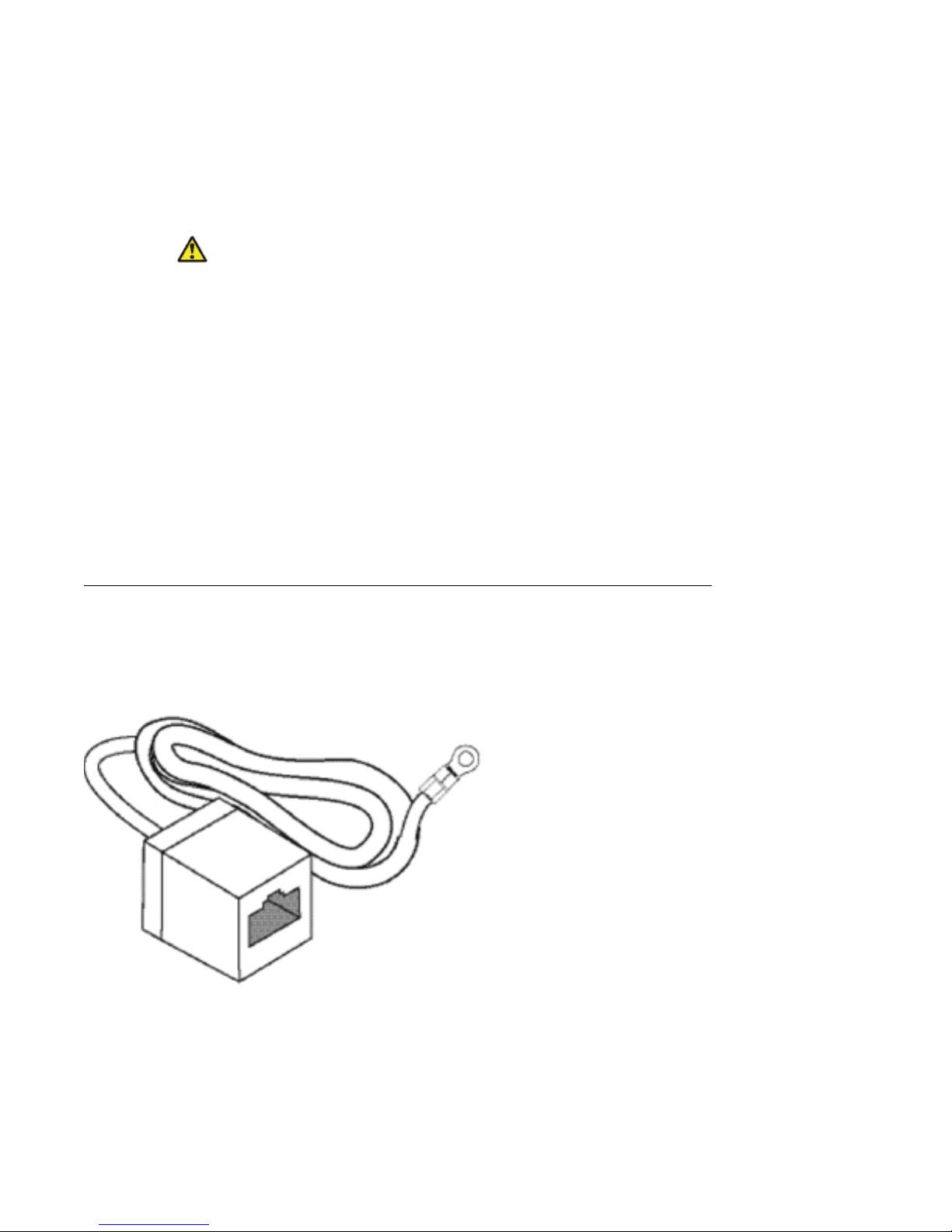
Preventing electrostatic damage in new cable installations
With new cable installations, Avaya recommends that you use an ESD discharge cable to
reduce the potential for damage from static, that can build up in cables. The following figure
illustrates an ESD cable.
Figure 1: Job aid
To install the ESD discharge cable, perform this procedure.
18 Installation November 2010
Page 19
1. Connect the ground lug on the ESD discharge cable to a safe and suitable earth
ground.
2. Connect all RJ-45 cable connectors to the female RJ-45 connector of the ESD
discharge cable for at least 5 seconds, and then connect each RJ-45 cable
connector to the switch.
3. Leave cables connected to the networking equipment. After you connect cables to
networking equipment, the cables do not build up charge.
Environmental requirements
The following table provides the environmental requirements for the individual switches in this
series. Ensure that the area where you install the switch and where it operates meets these
requirements.
Table 2: Avaya Ethernet Routing Switch 4500 Series environmental requirements
Environmental requirements
Environmental
requirement
Ambient Temperature 0C to 50C, continuous operation
Operating Temperature 0C to 50C
Storage Temperature –40C to 85C
Operating Humidity 0 to 95 percent noncondensing
Operating Relative
Humidity
Storage Relative Humidity 10 to 90 percent noncondensing
Maximum Operating
Altitude
Altitude 0 to 10 000 feet above sea level
Storage Altitude –1 000 to 40 000 feet above sea level
Acoustic Noise Less than or equal to 45 db at 35C and less than or equal to
Miscellaneous Operating
Considerations
Avaya Ethernet Routing Switch 4500 Series models
10 to 90 percent noncondensing
10 000 feet above sea level
57 db at 50C. The temperature is allowed to have ±3.5C
deviation around the threshold of 35C, (measurement
methods based on ISO 7779).
• No heat sources such as hot air vents or direct sunlight near
the switch.
Installation November 2010 19
• No sources of severe electromagnetic interference near the
switch.
• No excessive dust in the environment.
Page 20
Installing the Avaya Ethernet Routing Switch
Environmental
requirement
Warning:
To avoid bodily injury from hazardous electrical shock and current, never remove the top of
the device. No user-serviceable components are inside. For a translation of this statement,
see Translations of safety messages on page 63.
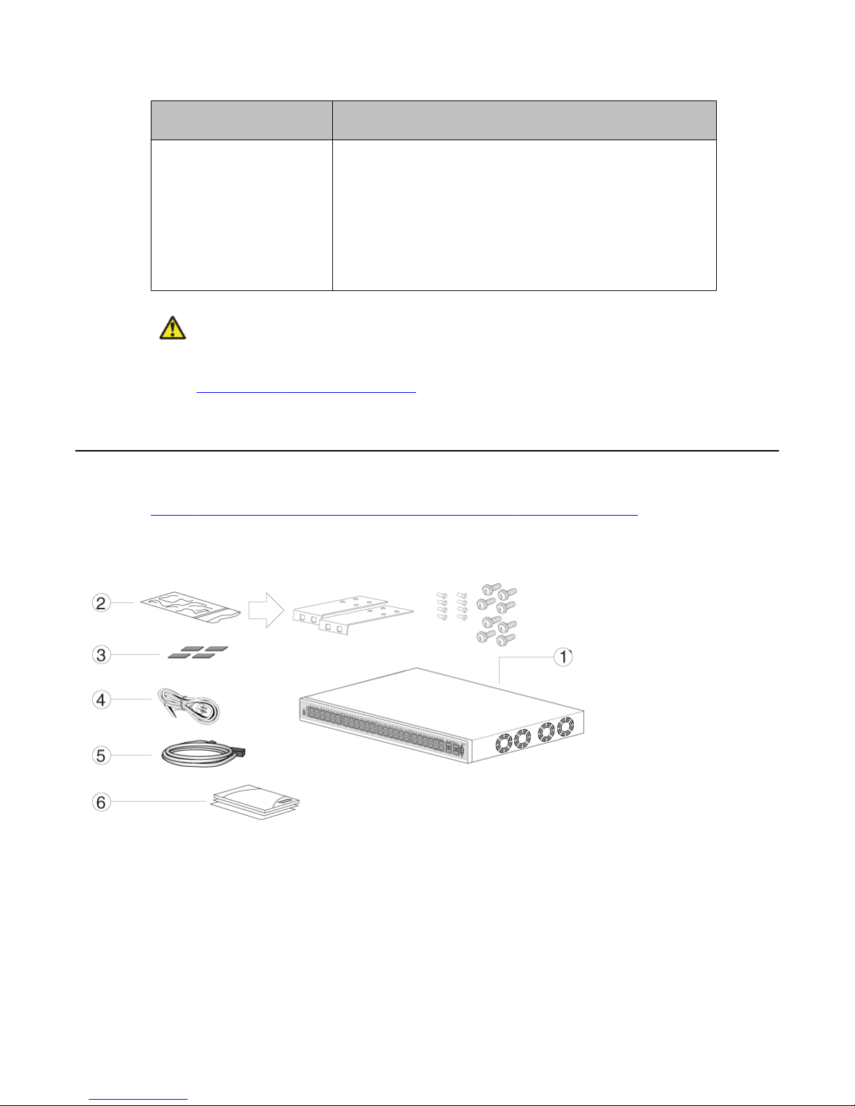
Package contents
Figure 2: Avaya Ethernet Routing Switch 4500 Series package contents on page 20
illustrates the components that are provided with each switch in the 4500 Series. If any
components are missing, contact the switch vendor.
Avaya Ethernet Routing Switch 4500 Series models
• An adequate power source is within 6 feet (1.83 meters) of
the switch. One 15-amp circuit is required for each power
supply.
• At least 2 inches (5.08 centimeters) of clearance on each
side of the switch unit for ventilation.
• Adequate clearance at the front and rear of the switch for
access to cables.
Figure 2: Avaya Ethernet Routing Switch 4500 Series package contents
1. Avaya Ethernet Routing Switch 4500 Series
2. Rack-mounting hardware that includes:
• Rack-mount brackets
20 Installation November 2010
Page 21

Installing the Avaya Ethernet Routing Switch 4500 Series on a table or shelf
• Screws to attach brackets to the switch
• Screws to attach the switch to the equipment rack
3. Rubber footpads
4. AC power cord
5. Standard 1.5 foot (45 cm) stacking cable
6. Documentation
Note:
Cable trays can be provided as an option.
Installing the Avaya Ethernet Routing Switch 4500 Series on
a table or shelf
You can install a single 4500 Series Avaya Ethernet Routing Switch on any flat surface. The
surface must support the combined weight of the switch and attached cables (from 15 and 20
pounds [7 to 9 kilograms]).
To install a 4500 Series switch on a table or shelf, perform this procedure.
Caution:
Do not place an Avaya Ethernet Power Supply Unit or Avaya Ethernet Redundant Power
Supply on top of an Avaya Ethernet Routing Switch 4500 Series. The switch housing of a
4500 Series Avaya Ethernet Routing Switch cannot support the weight of these units. For a
translation of this statement, see Translations of safety messages on page 63.
1. Attach the included rubber footpads on the bottom of the switch at the locations.
Installation November 2010 21
Page 22

Installing the Avaya Ethernet Routing Switch
2. Set the switch on a table or shelf as illustrated below. Allow at least 2 inches (5.1
centimeters) on each side for proper ventilation and at least 5 inches (12.7
centimeters) at the back for power cord clearance.
Installing the Avaya Ethernet Routing Switch 4500 Series in
an equipment rack
To install a 4500 Series switch in an equipment rack, perform this procedure.
22 Installation November 2010
Page 23

Installing the Avaya Ethernet Routing Switch 4500 Series in an equipment rack
Prerequisites for installing the Avaya Ethernet Routing Switch 4500 Series in an equipment
rack
• Ensure that you have a space of 1.75 inches (4.45 centimeters) in height for each switch in
an EIA or IEC-standard 19-inch (48.2-centimeter) equipment rack.
• The rack is bolted to the floor and braced if necessary.
• The rack is grounded to the same grounding electrode used by the power service in the
area. The ground path must be permanent and must not exceed 1 Ohm of resistance
from the rack to the grounding electrode.
Caution:
When you mount the device in a rack, do not stack units directly on top of one another. You
must secure each unit to the rack with the appropriate mounting brackets. Mounting brackets
cannot support multiple units. For a translation of this statement, see Translations of safety
messages on page 63.
1. Attach a bracket to each side of the switch using a #2 Phillips screwdriver as
illustrated in below.
2. Slide the switch into the rack as illustrated.
3. Insert and tighten the rack-mount screws using a #2 Phillips screwdriver.
Installation November 2010 23
Page 24

Installing the Avaya Ethernet Routing Switch
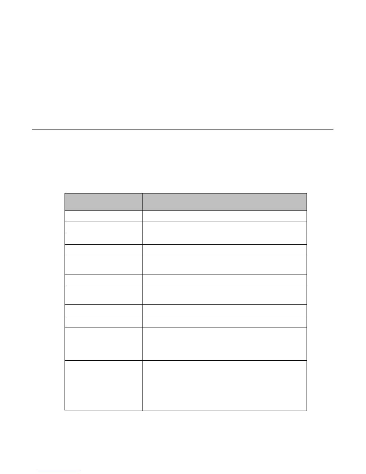
Cable requirements for the Avaya Ethernet Routing Switch
4500 Series
The following table describes the cables required for a an Avaya Ethernet Routing Switch 4500
Series switch.
Table 3: Switch cable requirements
Required Cable Description
10/100/1000Base TX Ports The interconnect cabling must conform to the Cat5e, Cat6,
or Cat6e specification of the Commercial Building
Telecommunications Cabling Standard, ANSI/TIA/EIA
568-B fitted with an RJ-45 Module jack.
10/100Base TX Ports The interconnect cabling for 10BaseT Ethernet must
conform to Cat3, Cat4, Cat5 (or better) UTP cabling for
distances up to 100 meters.
The interconnect cabling for 100BaseTX Fast Ethernet
must conform to Cat5 (or better) UTP cabling for distances
up to 100 meters.
100BaseFX Ports The interconnect cabling must conform to 50/125 or
62.5/125 micron multimode fiber-optic cabling for
distances up to 3 kilometers.
Console Port Serial cable with a DB-9 female connector on both ends.
The maximum length for the console port cable is 25 feet
(8.3 meters).
SFP Transceiver Ports Varies with the installed SFP transceiver. See the
documentation shipped with the SFP transceiver for
specifications.
USB Port USB 2.0 Type A-compliant cable.
Important:
In Autonegotiation mode, the Avaya Ethernet Routing Switch 4500 Series automatically
provides the proper MDI/MDI-X connection on the RJ-45 ports; to eliminate the need for
crossover cables. After you disable Autonegotiation on 10/100 ports, MDI/MDI-x is also
disabled.
24 Installation November 2010
Page 25

Installation and removal of Small Form-factor Pluggable (SFP) transceivers
Installation and removal of Small Form-factor Pluggable
(SFP) transceivers
The following section describes how to install and remove SFP transceivers in the Avaya
Ethernet Routing Switch 4500 Series. For complete information about SFP transceiver use
and designation, see Installing SFP and XFP Transceivers and GBICs (318034-D).
Important:
The switch will display the interface speed of the T1/E1 SFP as a 100 Mb/s connection even
though the interfaces is operating at the appropriate WAN speed. The system uses this value
for STP path cost and MLT utilization.
Avaya recommends that you enable egress traffic shaping on the port to 1.544 Mbps when
using the T1 SFP to guarantee appropriate Quality of Service and traffic prioritization.
Installing SFP transceivers
Install SFP transceivers by performing this procedure.
1. Remove the transceiver from the protective packaging.
2. Verify that the transceiver is the correct model for the network configuration.
3. Grasp the transceiver between your thumb and forefinger.
4. Insert the transceiver into the proper module on the switch. Apply a light pressure
to the transceiver until it clicks and locks into position in the module.
Installation November 2010 25
Page 26

Installing the Avaya Ethernet Routing Switch
5. Remove the dust cover from the transceiver optical bores.
Removing of SFP transceivers
Remove SFP transceivers by performing this procedure.
1. Disconnect the network fiber cable from the transceiver.
2. Use the locking mechanism on the transceiver to release it. The locking mechanism
varies from model to model as illustrated below.
3. Slide the transceiver from the module slot.
26 Installation November 2010
Page 27

4. If the transceiver does not slide easily from the module slot, use a gentle side-toside rocking motion while firmly pulling the transceiver from the slot.
5. Attach a dust cover over the fiber-optic bores and store the transceiver in a safe
place until you need it.
Important:
Discard transceivers in accordance with the proper laws and regulations.
RJ-45 connector pin assignments
The following section describes the connector pin assignments for the RJ-45 connectors in the
Avaya Ethernet Routing Switch 4500 Series switches.
Navigation:
•
Table 4: 4524GT, 4526GTX and 4548GT RJ-45 connector pin assignments on page
27
RJ-45 connector pin assignments
• Table 5: 4524GT-PWR, 4526GTX-PWR and 4548GT-PWR RJ-45 connector pin
assignments on page 28
• Table 6: 4526T and 4550T RJ-45 connector pin assignments on page 28
• Table 7: 4526T-PWR and 4550T-PWR RJ-45 connector pin assignments on page 29
Table 8: 4526GTX-PWR, 4524GT-PWR, 4550T-PWR and 4526T-PWR PoE RJ-45
•
connector pin assignments on page 30
• Table 9: 4548GT-PWR PoE RJ-45 connector pin assignments on page 30
Avaya Ethernet Routing Switches 4524GT, 4526GTX and 4548GT
The following table describes the RJ-45 connector pin assignments in the Avaya Ethernet
Routing Switches 4524GT, 4526GTX and 4548GT.
Table 4: 4524GT, 4526GTX and 4548GT RJ-45 connector pin assignments
Connector Pin Number Signal for 10/100Base T
MDI configuration
1 Output transmit data +
(TX–)
2 Output transmit data - (TX–) Input receive data - (RX–)
Signal for 10/100BaseT
MDI-X configuration
Input receive data + (RX–)
3 Input receive data + (RX+) Output transmit data + (TX
Installation November 2010 27
+)
Page 28

Installing the Avaya Ethernet Routing Switch
Connector Pin Number Signal for 10/100Base T
MDI configuration
6 Input receive data - (RX+) Output transmit data - (TX
4, 5, 7, 8 Not used Not used
Signal for 10/100BaseT
MDI-X configuration
+)
Avaya Ethernet Routing Switches 4524GT-PWR, 4526GTX-PWR and
4548GT-PWR
The following table describes the RJ-45 connector pin assignments in the Avaya Ethernet
Routing Switches 4524GT-PWR, 4526GTX-PWR and 4548GT-PWR.
Table 5: 4524GT-PWR, 4526GTX-PWR and 4548GT-PWR RJ-45 connector pin
assignments
Connector Pin Number Signal for 1GBaseT MDI
configuration
1 TP0+ TP1+
2 TP0– TP1–
Signal for 1GBaseT MDI-
X configuration
3 TP1+ TP0+
4 TP2+ TP3+
5 TP2– TP3–
6 TP1– TP0–
7 TP3+ TP2+
8 TP3– TP2–
Avaya Ethernet Routing Switches 4526T and 4550T
The following table describes the RJ-45 connector pin assignments in the Avaya Ethernet
Routing Switches 4526T and 4550T.
Table 6: 4526T and 4550T RJ-45 connector pin assignments
Connector
Pin Number Signal for 10/100Base T
MDI configuration
1 Output transmit data +
(TX–)
Signal for 10/100BaseT
MDI-X configuration
Input receive data + (RX–)
2 Output transmit data - (TX–) Input receive data - (RX–)
28 Installation November 2010
Page 29

RJ-45 connector pin assignments
Connector Pin Number Signal for 10/100Base T
MDI configuration
3 Input receive data + (RX+) Output transmit data + (TX
6 Input receive data - (RX+) Output transmit data - (TX
4, 5, 7, 8 Not used Not used
Signal for 10/100BaseT
MDI-X configuration
+)
+)
Avaya Ethernet Routing Switches 4526T-PWR and 4550T-PWR
The following table describes the RJ-45 connector pin assignments in the Avaya Ethernet
Routing Switches 4526T-PWR and 4550T-PWR.
Table 7: 4526T-PWR and 4550T-PWR RJ-45 connector pin assignments
Connector Pin Number Signal for 1GBaseT MDI
configuration
1 TP0+ TP1+
2 TP0– TP1–
Signal for 1GBaseT MDI-
X configuration
3 TP1+ TP0+
4 TP2+ TP3+
5 TP2– TP3–
6 TP1– TP0–
7 TP3+ TP2+
8 TP3– TP2–
Avaya Ethernet Routing Switches 4526GTX-PWR, 4524GT-PWR,
4550T-PWR and 4526T-PWR PoE
The following table describes the Power over Ethernet (PoE) RJ-45 connector pin assignments
in the Avaya Ethernet Routing Switches 4526GTX-PWR, 4524GT-PWR, 4550T-PWR and
4526T-PWR.
Installation November 2010 29
Page 30

Installing the Avaya Ethernet Routing Switch
Table 8: 4526GTX-PWR, 4524GT-PWR, 4550T-PWR and 4526T-PWR PoE RJ-45
connector pin assignments
Connector Pin Number Signal Description
1 RD+/power– Recieve Data+/power–
2 RD–/power– Receive Data–/power–
3 TD+/power+ Transmit Data+/power+
4 Not applicable Not applicable
5 Not applicable Not applicable
6 TD–/power+ Transmit Data–/power+
7 Not applicable Not applicable
8 Not applicable Not applicable
Avaya Ethernet Routing Switch 4548GT-PWR PoE
The following table describes the Power over Ethernet (PoE) RJ-45 connector pin assignments
in the Avaya Ethernet Routing Swtich 4548GT-PWR.
Table 9: 4548GT-PWR PoE RJ-45 connector pin assignments
Connector Pin Number Signal Description
1 RX+/power– Recieve Data+/power–
2 RX–/power– Receive Data–/power–
3 TX+/power+ Transmit Data+/power+
4 Not applicable Not applicable
5 Not applicable Not applicable
6 TX–/power+ Transmit Data–/power+
7 Not applicable Not applicable
8 Not applicable Not applicable
Important:
The Avaya Ethernet Routing Switch 4548GT-PWR uses pins 1, 2, 3, and 6 for PoE, and is
compliant with Alternative A (MDI-X) in IEEE802.3af.
30 Installation November 2010
Page 31

Console port pin assignments
The following table describes the console port pin assignments in the Avaya Ethernet Routing
Switch 4500 Series.
Important:
Avaya Ethernet Routing Switch 4500 Series supports only CLI Quickstart use on the console
port.
Table 10: Console port pin assignments
Connector Pin Number Signal
1 Carrier detect (not used)
2 Transmit Data (TXD)
3 Receive Data (RXD)
Console port pin assignments
4 Data terminal ready (not used)
5 Signal ground (GND)
6 Not used
7 Request to send (not used)
8 Not used
9 Ring indicator (not used)
Universal Serial Bus (USB) ports
The Avaya Ethernet Routing Switch 4500 Series switches feature a USB port on the left side
of the front panel. Switch administrators can use the USB port to perform tasks, previously
performed through Trivial File Transfer Protocol (TFTP), with a USB Mass Storage Device (for
example, a flash drive or thumb drive):
• download software
• generate and download the ASCII configuration file
• generate and download the binary configuration file
The storage capacity of the USB device in use limits file and system operations.
Support is available only for USB drives that comply with the Mass Storage subsection of the
USB 1.1 and USB 2.0 specification. Support does not extend to third-party devices that do not
comply with these standards. Off-the-shelf drives that do not comply with these standards
Installation November 2010 31
Page 32

Installing the Avaya Ethernet Routing Switch
cannot operate with the switch. Consult the documentation provided with the USB drive to
ensure compliance with these standards.
Resetting the switch to the default configuration
The restore factory-default command resets the switch or stack to its default
configuration.
To reset the switch or stack to its default configuration perform the following procedure.
1. Enter restore factory-default.
The following message appears:
Warning the switch/stack will be reset to factory default
configuration. Do you wish to continue (y/n) ?
2. Enter y to restore the switch to default.
Important:
If you enter restore factory-default [-y], the[-y] parameter instructs
the switch not to prompt for confirmation.
The restore factory-default command is in the privileged exec command mode.
For more information on USB ASCII Config Support, refer to the Avaya Ethernet Routing Switch
4500 Series Configuration — System (NN47205-500).
Power specifications for the Avaya Ethernet Routing Switch
4500 Series
This section describes power specifications for the switches in the 4500 Series.
For information specific to your switch, Avaya Ethernet Routing Switch 4500 Series—
Installation NN47205-300.
Note:
If you connect one type of Power over Ethernet switch to another, for example a 4548GTPWR and a 4550T-PWR, one switch may deliver power to the other. This is due to the PoE
Legacy Type Detection. Workaround: Legacy detection can be disabled on the switch if you
are not using any PoE devices which require legacy detection. An alternate solution is to
administratively disable Power over Ethernet on ports interconnecting any two Power over
Ethernet switches.
32 Installation November 2010
Page 33

Power specifications for the Avaya Ethernet Routing Switch 4500 Series
Avaya Ethernet Routing Switch 4548GT, 4550T, 4526FX, 4526T,
4524GT, and 4526GTX
The following table describes the regulatory AC power specifications for the Avaya Ethernet
Routing Switch 4526FX, 4526T, 4550T, 4524GT, 4526GTX and 4548GT non-PoE switches. It
should be noted that regulatory power specifications are based on the maximum rated capacity
of the power supplies and are not based on typical power consumption which is typically lower.
Table 11: AC power specifications
4548GT 4550T 4526FX 4526T 4526GTX 4524GT
Input
Current:
Input
Voltage
(rms):
Power
Consump
tion:
Thermal
Rating:
1.5 to 3.0A 1.5 to 3.0A 1.5 to 3.0A 1.5 to 3.0A 1.5 to 3.0A 1.5 to 3.0A
100 to
240VAC at
50 to 60 Hz
150W
maximum
415 BTU/
Hr
maximum
100 to
240VAC at
50 to 60 Hz
150W
maximum
240 BTU/
Hr
maximum
100 to
240VAC at
50 to 60 Hz
150W
maximum
256 BTU/Hr
maximum
100 to
240VAC at
50 to 60 Hz
150W
maximum
188 BTU/
Hr
maximum
100 to
240VAC at
50 to 60 Hz
150W
maximum
307 BTU/
Hr
maximum
100 to
240VAC at
50 to 60 Hz
150W
maximum
290 BTU/
Hr
maximum
Avaya Ethernet Routing Switch 4548GT-PWR, 4550T-PWR, 4526TPWR, 4526GTX-PWR, and 4524GT-PWR
The following table describes the regulatory AC power specifications for the Avaya Ethernet
Routing Switch 4526T-PWR, 4550T-PWR, 4524GT-PWR, 4526GTX-PWR, and 4548GTPWR switches. It should be noted that regulatory power specifications are based on the
maximum rated capacity of the power supplies and are not based on typical power
consumption which is typically lower.
Table 12: AC power specifications
4548GT- PWR 4550T-PWR 4526T-PWR 4526GTX-
Input
Current:
Input
Voltage
(rms):
Installation November 2010 33
3.3 to 6.5A 3.3 to 6.5A 3.3 to 6.5A 3.3 to 6.5A 3.3 to 6.5A
100 to 240VAC
50 to 60 Hz
100 to
240VAC at 50
to 60 Hz
100 to
240VAC at 50
to 60 Hz
PWR
100 to
240VAC at
50 to 60 Hz
4524GT-
PWR
100 to
240VAC at
50 to 60 Hz
Page 34

Installing the Avaya Ethernet Routing Switch
4548GT- PWR 4550T-PWR 4526T-PWR 4526GTX-
PWR
Power
Consumpti
on:
Thermal
Rating:
Inrush
Current:
Turn on
Condition:
Important:
12 V output rise time, from 10 to 90 percent, must be the maximum of 50 ms and
monotonic under all defined input and output conditions.
587W
maximum
788 BTU/Hr 615 BTU/Hr
20A 120VAC
at maximum
load, 40A
240VAC at
maximum load
1 second
maximum after
application of
AC power
587W
maximum
maximum
20A 120VAC
at maximum
load, 40A
240VAC at
maximum
load
1 second
maximum
after
application of
AC power
587W
maximum
375 BTU/Hr
maximum
70A 120VAC
at maximum
load, 40A
240VAC at
maximum
load
1 second
maximum
after
application of
AC power
587W
maximum
546 BTU/Hr
maximum
70A
120VAC at
maximum
load, 40A
240VAC at
maximum
load
1 second
maximum
after
application
of AC power
4524GT-
PWR
587W
maximum
546 BTU/Hr
maximum
70A
120VAC at
maximum
load, 40A
240VAC at
maximum
load
1 second
maximum
after
application
of AC power
Efficiency: 70 percent
minimum
70 percent
minimum
70 percent
minimum
70 percent
minimum
70 percent
minimum
Avaya Ethernet Routing Switch Redundant Power Supply 15
power specification
The Avaya Ethernet Routing Switch Redundant Power Supply 15 (RPS 15) provides a
secondary power source for Avaya Ethernet Routing Switch 4500 Series devices. In addition,
when connected to a Power over Ethernet (PoE) switch, such as the 4548GT-PWR or the
4550T-PWR, the RPS 15 can supplement the amount of Direct to Ethernet (DTE) power to
deliver up to 740 watts of PoE.
Avaya DC to DC converter module
To use the Avaya Ethernet Routing Switch Redundant Power Supply Model 15 (RPS 15) with
the Avaya Ethernet Routing Switch 4500 Series non-PoE models, 4548GT, 4550T, 4526FX,
4526T, 4524GT, and 4526GTX require a DC-DC converter module. The DC-DC converter
module plugs into the slot on the back of a non-PoE switch and connects the RPS to the switch.
34 Installation November 2010
Page 35

For information about connecting the converter module to the Avaya Ethernet Routing Switch
4500 Series non-PoE models, 4548GT, 4550T, 4524GT, or 4526FX, see DC-DC Converter
Module for the Baystack 4000 Series Switch.
Connect AC power
This section explains power cord specifications and how to connect AC power.
Power cord specifications
To connect AC power to the switch, you need an appropriate AC power cord as described in
Table 13: International power cord specifications on page 35. See the following table for
the
plug specifications.
Table 13: International power cord specifications
Connect AC power
Country and Plug Specification Specifications Typical Plug
Continental Europe:
• CEE7 standard VII male plug
• Harmonized cord (HAR marking on the outside of
the cord jacket to comply with the CENELEC
Harmonized Document HD-21)
United States of America, Canada, and Japan:
• NEMA5-15P male plug
• UL-recognized (UL stamped on cord jacket)
• CSA-certified (CSA label secured to the cord)
United Kingdom:
• BS1363 male plug with fuse
• Harmonized cord
Australia:
AS3112-1981 male plug
• 220 or 230VAC
• 50 Hz
• Single phase
• 100 or 120VAC
• 50–60 Hz
• Single phase
• 240VAC
• 50 Hz
• Single phase
• 240VAC
• 50 Hz
Installation November 2010 35
• Single phase
Page 36

Installing the Avaya Ethernet Routing Switch
Danger:
Using power cords with a proper grounding path
Use only power cords that have a grounding path. Without a proper ground, a person who
touches the switch is in danger of receiving an electrical shock. Lack of a grounding path to
the switch can result in excessive emissions. For a translation of this statement, see
Translations of safety messages on page 63.
Connect power to the back panel
Connect the AC power cord to the back of the switch, and then connect the cord to an AC
power outlet. The following figure shows how to connect the AC power cord to the switch back
panel.
Important:
The Avaya Ethernet Routing Switch 4500 Series has no AC power switch. When you
connect the power cord to a suitable, energized AC power outlet, the switch powers up
immediately.
Figure 3: Connecting AC power to the back panel
Warning:
Disconnecting the AC power cord is the only way to turn off AC power to the Avaya Ethernet
Routing Switch 4500 Series. Always connect the AC power cord in a quickly and safely
accessible location in case of an emergency. For a translation of this statement, see
Translations of safety messages on page 63.
36 Installation November 2010
Page 37

Check Light Emitting Diode (LED) on the Avaya Ethernet Routing Switch 4500 Series
Check Light Emitting Diode (LED) on the Avaya Ethernet
Routing Switch 4500 Series
The figures and tables in the following sections describe the LEDs on the Avaya Ethernet
Routing Switch 4500 Series switches. The tables describe LED operation for a switch that
finishes the power-on self-test.
Front panel LEDs
The following diagrams illustrate the components on the front panels of the Avaya Ethernet
Routing Switch 4500 Series switches:
Figure 4: Avaya Ethernet Routing Switch 4548GT on page 38
•
• Figure 5: Avaya Ethernet Routing Switch 4548GT-PWR on page 38
• Figure 6: Avaya Ethernet Routing Switch 4550T on page 39
•
Figure 7: Avaya Ethernet Routing Switch 4550T-PWR on page 39
• Figure 8: Avaya Ethernet Routing Switch 4526FX on page 39
• Figure 9: Avaya Ethernet Routing Switch 4526T on page 40
• Figure 10: Avaya Ethernet Routing Switch 4526T-PWR on page 40
• Figure 13: Avaya Ethernet Routing Switch 4526GTX on page 41
• Figure 14: Avaya Ethernet Routing Switch 4526GTX-PWR on page 42
• Figure 11: Avaya Ethernet Routing Switch 4524GT on page 41
•
Figure 12: Avaya Ethernet Routing Switch 4524GT-PWR on page 41
For detailed explanations of the states indicated by each front panel LED type, see the following
sections:
• Switch LED state indicators on page 42
• Port LED state indicators on page 43
• Table 16: SFP transceiver Port LED state indicators on page 44
Installation November 2010 37
Page 38

Installing the Avaya Ethernet Routing Switch
Figure 4: Avaya Ethernet Routing Switch 4548GT
Figure 5: Avaya Ethernet Routing Switch 4548GT-PWR
1. USB port 4. Shared SFP Transceiver Ports (LEDs
2. Switch LEDs 5. Console Port
3. 10/100/1000 Ports (LEDs above ports)
above ports)
38 Installation November 2010
Page 39

Check Light Emitting Diode (LED) on the Avaya Ethernet Routing Switch 4500 Series
Figure 6: Avaya Ethernet Routing Switch 4550T
Figure 7: Avaya Ethernet Routing Switch 4550T-PWR
1. USB port 4. combo 10/100/1000 SFP ports (LEDs
2. Switch LEDs 5. Console port
3. 10/100 ports (LEDs above ports)
Figure 8: Avaya Ethernet Routing Switch 4526FX
1. USB Port 4. combo 10/100/1000 SFP ports (LEDs
2. Switch LEDs 5. Console Port
3. 100BaseFX ports (LEDs above ports)
above ports)
above ports)
Installation November 2010 39
Page 40

Installing the Avaya Ethernet Routing Switch
Figure 9: Avaya Ethernet Routing Switch 4526T
1. USB Port 4. combo 10/100/1000/SFP ports
2. Switch LEDs 5. Console Port
3. 10/100 ports (LEDs above ports)
Figure 10: Avaya Ethernet Routing Switch 4526T-PWR
1. USB Port 4. combo 10/100/1000/SFP ports
2. Switch LEDs 5. Console Port
3. 10/100 ports (LEDs above ports)
40 Installation November 2010
Page 41

Check Light Emitting Diode (LED) on the Avaya Ethernet Routing Switch 4500 Series
Figure 11: Avaya Ethernet Routing Switch 4524GT
Figure 12: Avaya Ethernet Routing Switch 4524GT-PWR
1. USB Port 4. Shared SFP ports: can support low speed
2. Switch LEDs 5. Console Port
3. 10/100/1000 ports (LEDs above ports)
Figure 13: Avaya Ethernet Routing Switch 4526GTX
1. USB Port 4. 10/100/1000 RJ-45 ports (LEDs above
SFPs, for example — 100FX SFP
ports)
2. Switch LEDs 5. Shared SFP combo ports
Installation November 2010 41
Page 42

Installing the Avaya Ethernet Routing Switch
3. 10Gig XFP slots 6. Console Port
Figure 14: Avaya Ethernet Routing Switch 4526GTX-PWR
1. USB Port 4. 10/100/1000 ports (LEDs above ports)
2. Switch LEDs 5. Shared SFP ports
3. 10Gig XFP slots 6. Console Port
Warning:
Fiber optic equipment can emit laser or infrared light that can injure your eyes. Never look
into an optical fiber or connector port. Always assume that fiber-optic cables are connected
to a light source. For a translation of this statement, see Translations of safety messages on
page 63.
Switch LED state indicators
Table 14: Switch LED state indicators on page 42 describes the main switch LED state
indications provided by LED color and fluctuation cues.
Table 14: Switch LED state indicators
Label Color and Status Description
Pwr Green, steady The switch is receiving power.
Off The switch is not receiving power, either from an AC
Status Green, steady
power source or the redundant power supply (RPS).
• During start-up: The power-on self-test (POST) is
complete and the switch is operating normally.
• After start-up: The switch is running the agent code
successfully.
42 Installation November 2010
Page 43

Check Light Emitting Diode (LED) on the Avaya Ethernet Routing Switch 4500 Series
Label Color and Status Description
Off The switch failed the power-on self-test (POST) or
failed to load the agent code.
RPS Green, steady The switch is connected to a redundant power supply
unit (RPS) and is receiving power if necessary.
Off The switch is not connected to a RPS, the RPS is not
supplying power, or the DC/DC module is not
supplying power.
Up Green, steady The Cascade Up port has a physical connection to
another unit.
Amber, steady The Cascade Up port has detected an error.
Off The switch is in stand-alone mode or no link exists to
the Cascade Up port.
Down Green, steady The Cascade Down port has a physical connection to
another unit.
Amber, steady The Cascade Down port detected an error.
Off The switch is in stand-alone mode or no link exists to
Base Green, steady The switch is the stack base unit.
Green, blinking A configuration error occurred. Either multiple base
Amber, steady The switch is operating as the temporary base unit in
Off The switch is not the stack base unit or it is operating
Port LED state indicators
This section describes the port LED state indicators by color and fluctuation cues.
The following list describes the three port LEDs:
• Activity indicates the level of activity on the link.
• Link indicates the presence of an Ethernet link.
• Speed indicates the port speed (for example, 10 Mb/s, 100 Mb/s, 1000 Mb/s).
the Cascade Down port.
units or no base units are configured in the stack.
the stack configuration.
in stand-alone mode.
Installation November 2010 43
Page 44

Installing the Avaya Ethernet Routing Switch
Table 15: RJ-45 Port LED state indicators
Label Color and Status Description
Speed/PoE Green, Pulse Green
—Green
Green, Steady The port is set to operate at 1000 Mb/s on gigabit PoE
Amber, Pulse Amber
—Amber
Amber, Steady The port is set to operate at 100 Mb/s on gigabit PoE
Amber, Green Pulse The port is experiencing a PoE error.
Off When the Link/Activity LED is green and the Speed
The port is set to operate at 1000 Mb/s on gigabit PoE
models (ERS 4524GT-PWR, 4526GTX-PWR and
4548GT-PWR) and 100 Mb/s on the Fast Ethernet
models (ERS 4526T-PWR & 4550T-PWR).
models (ERS 4524GT, 4526GTX and 4548GT) and
100 Mb/s on the Fast Ethernet models (ERS 4526T
& 4550T).
The port is set to operate at 100 Mb/s on gigabit PoE
models (ERS 4524GT-PWR, 4526GTX-PWR and
4548GT-PWR) and 100 Mb/s on the Fast Ethernet
models (ERS 4526T-PWR & 4550T-PWR).
models (ERS 4524GT, 4526GTX and 4548GT) and
100 Mb/s on the Fast Ethernet models (ERS 4526T
& 4550T).
LED is off, the port is set to operate at 10 Mb/s for all
gigabit models (ERS 4524GT, 4526GTX, 4548GT,
4524GT-PWR, 4526GTX-PWR and 4548GT-PWR).
Link /
Activity
Green, Steady The link established but no data activity exists.
Green, Blink The link is established and data activity exists (the
blink rate indicates the level of activity).
Green, Slow Blink The software disabled the port.
Amber, Steady Port not used.
Amber, Blink Not applicable.
Off The port has no link or activity.
Table 16: SFP transceiver Port LED state indicators
Label Color and Status Description
In Use Green, Blink Not applicable.
Green, Steady The SFP port and the transmit port are active.
Amber, Blink Not applicable.
Amber, Steady SFP Installed—TX Port Inactive
Off No SFP transceiver is present.
44 Installation November 2010
Page 45

Set IP parameters for the Avaya Ethernet Routing Switch 4500 Series
Label Color and Status Description
Link / Activity Green, Blink Activity exists on the port.
Green, Slow Blink Software disabled this port.
Green, Steady The link is operating normally.
Off No link exists.
Note:
If you link two ports explicitly set for different speeds (for example one configured as
10BaseT and the other as 100BaseTX) the port link LED may indicate a link, but the switch
does not establish a link. Connect ports using the same set speed or use auto-negotiation
on each switch.
Set IP parameters for the Avaya Ethernet Routing Switch
4500 Series
After an Avaya Ethernet Routing Switch 4500 Series switch starts up and initializes all software
modules, it begins switching operations.
To manage the switch using Telnet or SNMP, or to perform TFTP operations, you must set
certain IP parameters. Also, if you intend to connect the switch to a stack configuration, you
must assign additional parameters to ensure proper stack operation.
You must configure the following IP parameters for initial switch setup:
• IP address of the switch or stack
• subnet mask
• gateway address
Navigation:
• Setting IP parameters using the console port and CLI Quickstart on page 45
Setting IP parameters using the console port and CLI on page 47
•
• Set IP parameters using IP.CFG file on a USB memory device on page 48
• Set IP parameters using bootp on page 51
• Setting IP parameters using the Web-based Management Interface on page 52
Setting IP parameters using the console port and CLI Quickstart
To set IP parameters for a switch configured with the factory default settings, perform the
following procedure using the console port and CLI Quickstart.
Installation November 2010 45
Page 46

Installing the Avaya Ethernet Routing Switch
1. Connect a terminal to the console port of the switch.
You can use any terminal or PC with an appropriate terminal emulator as the
management station.The following table lists the parameters that you must use with
any terminal emulation software used to connect to the switch.
Property Value
Baud Rate 9600 bps
Data Bits 8
Stop Bits 1
Parity None
Flow Control None
You require a console cable and connector to match the male DTE connector (DB-9)
on the switch to connect the terminal to the switch console port.
Note:
Autobaud is not supported. If you change the terminal speed and then reboot the
unit, non relevant characters appear in the display. Workaround: Use only 9600
(baud rate) for terminal speed.
2. Set the terminal protocol on the terminal or terminal emulation program to VT100
and VT100/ANSI.
3. Connect to the switch using the terminal or terminal emulation application.
4. When the switch configuration is set to factory default the following screen appears.
Enter the information requested at each prompt.
Welcome to the 4548GT-PWR setup utility. You will be
requested for information to initially configure for the
switch. When finished the information will be applied and
stored in the switch NVRAM. Once the basic parameters are
configured, additional configuration can proceed using other
management interfaces. Press ^C to abort at any time.
The in-band IP Address prompt line appears
Please provide the in-band IP Address[0.0.0.0]:10.127.232.30
The in-band sub-net mask prompt line appears
Please provide the in-band sub-net mask[0.0.0.0]:
255.255.255.0
The Default Gateway prompt line appears
46 Installation November 2010
Page 47

Set IP parameters for the Avaya Ethernet Routing Switch 4500 Series
Please provide the Default Gateway[0.0.0.0]:10.127.232.1
The Read-Only Community String prompt line appears
Please provide the Read-Only Community
String[**********]:******
The confirm Read-Only Community String prompt line appears
Please confirm the Read-Only Community
String[**********]:******
The Read-Write Community String prompt line appears
Please provide the Read-Write Community
String[**********]:*******
The confirm Read-Write Community String prompt line appears
Please confirm the Read-Write Community
String[**********]:*******
The Quick Start VLAN prompt line appears
Please provide the Quick Start VLAN <1-4094> [1]:
The Basic Switch parameters configuration confirmation appears
Basic switch parameters have now been configured and saved.
Important:
Avaya Ethernet Routing Switch 4500 Series only supports the Avaya CLI, the old 'Bay Stack'
menu interface is not supported on this product. When the switch is set to factory default
parameters, the CLI Quickstart appears which enables you to set default IP information.
Setting IP parameters using the console port and CLI
If the switch is configured beyond factory default settings, perform the following procedure to
set IP parameters using the console port and Command Line Interface (CLI):
1. Connect a terminal to the console port of the switch. You can use a terminal or PC
with an appropriate terminal emulator as the management station. See
parameters using the console port and CLI Quickstart on page 45.
Setting IP
2. Set the terminal protocol on the terminal or terminal emulation program to VT100
or VT100/ANSI.
3. Connect to the switch using the terminal or terminal emulation application.
Installation November 2010 47
Page 48

Installing the Avaya Ethernet Routing Switch
4. After the Avaya banner appears, press CTRL + Y to display the CLI prompt.
5. To enter the Global Configuration command mode, use the enable command.
6. At the prompt, enter the configure terminal command.
7. At the prompt, enter the ip address command to set the switch or stack IP
address.
Following is the ip address command syntax:
ip address [stack | switch} <ip address> [netmak <subnet
mask>] [default-gateway <gateway address>]
The following table describes the ip address command parameters.
Parameter Description
[stack | switch] Use either the stack or switch key word to set
<ip_address> The IP address to be used.
the appropriate IP address.
<subnet_mask> The subnet mask to be used.
<gateway_address> The default gateway address to be used.
The IP configuration is now complete.
To continue configuration, use the appropriate CLI commands.
To disconnect from the switch, use the logout command.
Set IP parameters using IP.CFG file on a USB memory device
If the switch does not obtain an IP address through BootP, you can load the IP address and
optionally new switch software and configuration from the USB memory device using the ip.cfg
file.
Note:
The file name, ip.cfg, is case-insensitive.
See also Universal Serial Bus (USB) ports on page 31
If a properly formatted file exists on a USB port, the switch uses that ip.cfg as the first option,
rather than the last. You can specify one or more of the optional parameters in the ip.cfg file.
All of the parameters are optional.
The following table describes the ip.cfg file parameters:
48 Installation November 2010
Page 49

Set IP parameters for the Avaya Ethernet Routing Switch 4500 Series
Table 17: IP.CFG file
Parameter Description
IP <xx.xx.xx.xx> Specifies the IP address for the switch. Example:
192.168.22.1
Mask <xx.xx.xx.xx> Specifies the network mask. Example: 255.255.255.0
Gateway <xx.xx.xx.xx> Specifies the default gateway. Example:
181.30.30.254
SNMPread <string> Specifies the SNMP read community string.
Example: public
SNMPwrite <string> Specifies the SNMP write community string.
Example: private
VLAN <number> Specifies the management VLAN-ID. Example:
VLAN 1
USBdiag <string> Specifies the filename of the diagnostic image to load
from the USB. Example: ers4500/
ers4500_5.1.0.4.bin
USBascii <string> Specifies the filename of the ASCII config file to load
from the USB. Example: customer1.cfg
USBagent <string> NEXTIP,
NEXTMask, and NEXTGateway
Specifies the filename of the agent image to load from
the USB and specifies IPs for next boot. Example:
ers4500/ers4500_5.2.0.0.img
Note:
If you download an ASCII file or diag/image with an Ip.cfg file, the specific ASCII file or diag/
image must be present on the usb device.
The ip.cfg file loads information from the ASCII configuration file in order of precedence. For
example, if you have an ip.cfg file with the following commands:
USBascii ip.txt
IP 181.30.30.113
Mask 255.255.255.0
Gateway 181.30.30.254
The stack IP becomes 181.30.30.113 no matter what IP address is in the ip.txt file.
If you have an ip.cfg file with the following commands:
IP 181.30.30.113
Mask 255.255.255.0
Gateway 181.30.30.254
USBascii ip.txt
The stack IP will be the IP address defined in the ip.txt file.
Installation November 2010 49
Page 50

Installing the Avaya Ethernet Routing Switch
Note:
The ip.cfg file runs only on a base or stand-alone unit. The file cannot be more than 4096
bytes or contain more than 200 lines.
The following figure shows an example of an ip.cfg file.
Figure 15: ip.cfg file example
If the ip.cfg file specifies an image or agent code, the switch loads the software, even if the
same version is already installed on the switch. Ensuring that the appropriate software is
always upgraded on the units is the correct operation of ip.cfg.
Use the factory default command to reset the switch to the factory default after you insert the
USB memory device in the USB port. The USB memory device must contain the properly
formatted ip.cfg file in the root directory.
Resetting the switch to default settings
Perform this procedure to reset the switch to the factory default settings with the ACLI.
1. Enter boot default.
2. Enter y to confirm the reset.
The Avaya Ethernet Routing Switch 4500 restarts with factory default settings and
attempts to read the ip.cfg file from an installed USB drive within three minutes. The
Avaya Ethernet Routing Switch 4500 banner page appears while the switch
retrieves the ip.cfg file.
Important:
If you have a console connected to the switch / stack, then while the system retrieves the
ip.cfg file from the USB memory device, the Avaya banner page appears. If you use the
serial console while the system is restarting or within the first few minutes after booting, then
the switch will not load the IP.CFG file. If you want the switch to load the configuration using
IP.CFG, Avaya recommends not interact with the switch via the console port for a period
of 3 minutes after booting the switch or stack. This is necessary to give the switch sufficient
time to load the IP.CFG file and take appropriate actions. If the switch is also performing an
50 Installation November 2010
Page 51

Set IP parameters for the Avaya Ethernet Routing Switch 4500 Series
automated update of the software, then this period of time will be increased as the switch
will need to perform an automatic reboot during the IP.CFG process to load the designated
software.
Checking the status of the download
Perform this procedure to check the status of the download three minutes after the Avaya
banner page appears.
Press CTRL and y keys together.
Two possible responses indicate a pass or fail status.
• Pass: The system opens the first page of menu.
• Fail: The system prompts you for an IP address.
You can confirm the successful download with the show ip command. If the USB ip.cfg file
download succeeded, all parameters read from the ip.cfg file show as present in the switch
and become part of the runtime configuration. If there is an error parsing the ip.cfg file, a log
entry provides an indication of the error encountered.
If you have disabled autosave, then save the configuration with the ACLI command, copy
config nvram. After the successful ip.cfg file download from the USB memory device, you
can manage the switch through Telnet and SNMP.
If you load any diagnostic or agent images with ip.cfg, the diagnostic or agent images need to
be on the same USB memory device. Restart the system after you download the ip.cfg files.
To ensure that diagnostic and agent image downloaded successfully, check in the system log or
audit log. If the operation is successful, restart the switch or stack to display the new diagnostic
and agent images.
If you download an ASCII file, you must enter the settings after the download. You do not need
to restart the switch or stack if you download an ASCII file.
Set IP parameters using bootp
The Avaya Ethernet Routing Switch 4500 Series switches are configured to obtain a
management IP address using BOOTP by default
If the switch is connected to the network and an appropriate bootp server is configured, then
the server assigns an IP address to the switch.
To view the assigned and in-use IP addresses, connect to the switch console and enter the
show ip command.
Installation November 2010 51
Page 52

Installing the Avaya Ethernet Routing Switch
Setting IP parameters using the Web-based Management Interface
To set IP parameters using the Web-based Management Interface, perform the following
procedure.
Prerequisites Ensure that the switch has an IP address.
1. Connect a computer to the switch through a data port using a standard RJ-45
network cable.
2. Open a Web browser on the attached computer and enter the IP address of the
switch in the following format: http://<nnn.nnn.nnn.nnn>. The main screen of the
Web-based Management Interface appears.
3. Choose Configuration > IP from the menu. The following figure appears.
4. Use the fields on the IP configuration screen to configure the IP parameters. All
fields are divided into three columns: Configurable, In Use, and Last BootP. Use
the Configurable column to configure a new value for the field. The In Use column
represents the current value used by the switch, and the Last BootP column
supplies a value assigned to the field by a BootP request. The following table lists
and describes the fields on the IP configuration screen.
Field Description
In-Band Stack IP
Address
In-Band Switch IP
Address
In-Band Subnet
Mask
52 Installation November 2010
The IP address used by the switch when it is part of a stack.
The IP address used by the switch when it is a standalone unit.
The subnet mask used by the switch.
Page 53

Avaya Ethernet Routing Switch 4500 series stacking
Default Gateway The default gateway used by the switch.
5. Click Submit.
Important:
Changes that occur to IP parameters during this procedure can result in the loss of browser
connectivity to the switch.
You must ensure that your IP address and subnet mask setting matches the IP address and
subnet mask setting of the network where the switch resides.
Avaya Ethernet Routing Switch 4500 series stacking
The Avaya Ethernet Routing Switch 4500 Series provides fail-safe stackability. You can
connect up to eight 4500 Series devices in a stack to provide uninterrupted connectivity for up
to 400 ports. You can manage the stack as a single unit.
Stack connector
The stack connector is a component of the Avaya Ethernet Routing Switch 4500 Series back
panel and consists of the Unit Select switch, Cascade Down connector, and Cascade Up
connector. The stack connector is illustrated in the
diagram.
Figure 16: Stack connector on page 54
Installation November 2010 53
Page 54

Installing the Avaya Ethernet Routing Switch
Figure 16: Stack connector
Unit Select switch
Use the Unit Select switch to designate a switch in the stack as the base unit. Slide the Unit
Select switch to the right to designate a switch as the base unit. You can designate only one
switch in a stack as the base unit; that is, with the switch in the base unit position. For all other
switches in the stack, the Unit Select switch must be in the left position.
The base unit designation for a switch appears on the front panel LED display. See
Switch LED state indicators on page 42.
Cascade Down connector
Use the Cascade Down connector to connect a switch to the next unit in the stack through a
cascade cable. Connect the other end of the Cascade Down cable to the Cascade Up
connector of the next switch in the stack. A return cable from the Cascade Down connector of
another unit to the Cascade Up connector of the first unit completes the stack connection. See
Figure 17: Simplified stacking diagram on page 55 and Figure 18: Connecting cascade
cables on page 56.
Table 14:
Important:
To create a stack connection, order the appropriate Avaya Ethernet Routing Switch 4500
Series cascade cables to ensure fail-safe stacking. A 1.5 foot stacking cable is included with
54 Installation November 2010
Page 55

the switch. For stacking three or more units (maximum eight units per stack), order the 5
ft, 10 ft, 14 ft or 16.4 ft. cables as applicable.
Cascade Up connector
The Cascade Up connector provides an attachment point that accepts a cascade cable
connection from another unit in the stack. A return cable from the Cascade Down connector
of one switch to the Cascade Up connector of an adjacent switch completes the stack
connection. See Figure 17: Simplified stacking diagram on page 55 and Figure 18:
Connecting cascade cables on page 56.
Figure 17: Simplified stacking diagram on page 55 illustrates a simple, two-switch stack
connection.
Avaya Ethernet Routing Switch 4500 series stacking
Figure 17: Simplified stacking diagram
Figure 18: Connecting cascade cables on page 56 illustrates a typical crossover connection
configuration. Failure to use this configuration can result in loss of connectivity.
Installation November 2010 55
Page 56

Installing the Avaya Ethernet Routing Switch
Figure 18: Connecting cascade cables
1. Base Unit
2. Cascade Cable (connected from Base Unit Cascade Down connector to Unit 2
Cascade Up connector)
3. Cascade Cable (connected from Unit 2 Cascade Down connector to Base Unit
Cascade Up Connector)
Initial installation unit number assignment
When you install the stack, the software automatically determines the physical order of all units
in the stack according to the position of the base unit within the stack. Thereafter, the individual
units maintain their original unit numbering, even if you change the position of one or more
units in the stack.
For example, when you initially power the stack, the base unit becomes unit 1 and the unit that
the base unit connects to (across the Cascade Down cable) becomes unit 2. The next unit is
designated as unit 3, this continues until the maximum stack configuration (up to eight units)
is reached. If another unit in the stack is designated as the base unit, the new base unit keeps its
originally designated unit number in the stack.
Stack MAC address
When a switch participates in a stack configuration, stack initialization automatically assigns
a stack MAC address. The stack MAC address is the base unit MAC address plus 1. If another
56 Installation November 2010
Page 57

unit in the stack is assigned as the base unit, the new stack MAC address is the MAC address of
the new base unit plus 1. The original stack IP address still applies to the new base unit.
Temporary base unit
If an assigned base unit fails, the next unit in the stack order automatically becomes the new
temporary base unit. The LED display on the front panel of the temporary base unit changes
to a steady amber state to indicate the change. When this happens, use the Unit Select switch
to designate the temporary base unit as the base unit until you repair or replace the failed base
unit.
You must designate a base unit because the automatic failover is only a temporary safeguard
and, if the original unit rejoins the stack, it does not resume base unit status. Also, if the stack
configuration loses power, the temporary base unit does not resume base unit status when
power is restored.
Important:
If the temporary base unit is not assigned as the new base unit, and the temporary base unit
fails, the next unit in the stack order becomes the temporary base unit. This process
continues after successive failures until only two units are left in the stack.
Avaya Ethernet Routing Switch 4500 series stacking
Redundant cascade stacking
The Avaya Ethernet Routing Switch 4500 Series allows a stack of up to eight units into a dualpath cascade stack. If any single unit fails, or if a cable is accidently disconnected, other units in
the stack remain operational.
In addition to increasing bandwidth, the software uses the cables to provide two paths between
units. If one path is interrupted, the data travels over the remaining path at half the normal
interswitch bandwidth.
Figure 19: Redundant cascade stacking on page 58 shows a typical example of a stack
configuration reacting to a failed connection in the stack configuration.
Installation November 2010 57
Page 58

Installing the Avaya Ethernet Routing Switch
Figure 19: Redundant cascade stacking
1. Base Unit
2. Last Unit
3. Unit selector switch
4. Cascade Cable
In the example, the following occur:
• Unit 3 becomes nonoperational due to a unit failure, cable disconnection, or a loss of
power.
• Units 2 and 4, directly upstream and downstream from Unit 3, sense the loss of link signals
from unit 3. The software directs all the data to traverse the remaining path.
• The Cascade Down LED for Unit 2 and the Cascade Up LED for Unit 4 turn amber to
indicate an error.
• The remaining stack units remain connected and continue to operate.
Replacing or adding a stack unit
To replace a failed stack unit or insert a new unit into a stack, perform this procedure.
Important:
Automatic Unit Replacement (AUR) for both configuration and software is enabled for all
Avaya Ethernet Routing Switch 4500 Series platforms and software releases. This means
that the agent code image, on a replacement unit, is automatically upgraded or downgraded
58 Installation November 2010
Page 59

Stack configurations
to match the software running on the stack. In addition, when a like-for-like replacement of
a failed unit occurs, any port-specific configuration is restored .
1. Remove the failed switch from the stack.
2. Obtain a like-for-like replacement switch.
3. With the new unit turned off, physically insert the new unit in the stack and reconnect
the stack cables.
4. Turn on the new unit. Depending on the software load on the replacement switch,
it can automatically restart one or two times before joining the stack as a fully
operational member.
5. Check the log file on the stack to ensure that the replacement unit correctly joined
the stack. The log file displays AUR information messages.
If you replace the base unit, remember that the stack has elected a temporary base unit and
the new unit does not automatically assume the base unit status. Configure the new unit as
the base unit, using the Unit Select switch, and reset the Unit Select switches of the other stack
members to nonbase units.
Remove a stack unit
If you remove a unit from the stack (to operate in stand-alone mode), the following switch
configuration settings revert to those configured before the unit became a member of the stack:
• IP address
• Web, Telnet, and SNMP passwords
• SNMP community strings
Stack configurations
Because stack parameters are associated with the base unit, the physical stack order depends
on the base unit position and whether you configure the stack cascade up (stack up) or cascade
down (stack down). This designation depends on the stack cabling arrangement. Avaya
recommends that you use Cascade Down configuration. See
Cascade down
Cascade down on page 59.
In a cascade down configuration, the base unit is located at the top of the stack. The system
automatically numbers the physical units based on the designated base unit (unit 1). The cable
connected to the Cascade Down connector of the base unit terminates in the Cascade Up
connector on the next unit in the stack, which is located below the base unit. This next unit is
designated unit 2. The stack is wired downward through the units and the system continues
Installation November 2010 59
Page 60

Installing the Avaya Ethernet Routing Switch
to number in this manner throughout the stack. In this configuration, the base unit discovers
the stack in a cascade down (stack down) direction. The following illustration demonstrates a
typical cascade down (stack down) configuration.
Figure 20: Cascade Down (Stack Down) configuration
1. Base Unit
2. Last Unit
3. Cascade Cable
4. Cascade Cable
Important:
Because many network management software packages assume a cascade down (stack
down) configuration, Avaya recommends that you use a cascade down configuration.
Cascade up
In a cascade up (stack up) configuration, the base unit is physically the top unit in the stack.
The cable connected to the Cascade Down connector of the base unit terminates in the
Cascade Up connector physically at the bottom of the stack. This next unit is designated unit
2. The stack is wired upward through the units and the system continues to number in this
manner throughout the stack. In this configuration, the base unit discovers the stack in a
60 Installation November 2010
Page 61

Stack configurations
cascade up (stack up) direction. The following illustration demonstrates a typical cascade up
(stack up) configuration.
Figure 21: Cascade Up (Stack Up) configuration
1. Base Unit
2. Last Unit
3. Cascade Down connector with cable connected
4. Cascade Cable
Important:
Because many network management software packages use a cascade down (stack down)
configuration, Avaya recommends that you use a cascade down configuration. See Cascade
down on page 59.
The following guidelines apply for stack configuration:
• When you apply power to the stack, the base unit initializes, typically within 60 seconds,
and the entire stack powers up as a single logical unit.
• You can attach an RS-232 communications cable to the console port of any switch in the
stack to establish a console connection.
Installation November 2010 61
Page 62

Installing the Avaya Ethernet Routing Switch
• You can perform a software upgrade on the stack from any switch using a Telnet session,
the Web-based Management Interface, or any SNMP-based management software.
• You can manage the stack using a Telnet session, Web-based Management Interface, or
any SNMP-based management software through any stack switch port.
• When you stack two or more switches, use the 3-foot cascade max-return cable
(AL4518002-E6) to complete the link from the last unit in the stack to the base unit.
62 Installation November 2010
Page 63

Chapter 5: Translations of safety messages
Caution:
When you mount this device in a rack, do not stack units directly on top of one another. You must secure
each unit to the rack with appropriate mounting brackets. Mounting brackets cannot support multiple
units.
Important:
Achtung:
Wenn diese Einheit in einem Rack montiert wird, muß ein gewisser Abstand zur nächsten Einheit
gelassen werden. Jede Einheit muß mit geeignetem Befestigungsmaterial gesichert werden. Das
Befestigungsmaterial ist nicht für die gleichzeitige Befestigung mehrerer Einheiten geeignet.
Important:
Si vous installez le module dans une baie, ne l'empilez pas directement sur un autre. Chaque module
doit être fixé à sa propre baie à l'aide des supports de montage appropriés. Ces supports ne sont pas
conçus pour résister à plusieurs modules.
Important:
Precautión:
Cuando monte este dispositivo en un bastidor, no apile las unidades directamente una encima de otra.
Cada unidad debe fijarse en el bastidor con las abrazaderas de montaje adecuadas. Las abrazaderas
de montaje no están diseñadas para sostener varias unidades.
Important:
Se il dispositivo viene installato in un rack, non impilare le unità direttamente una sull'altra. Ogni unità
deve essere fissata al rack con le staffe di montaggio appropriate. Le staffe di montaggio non sono
state progettate per supportare più unità.
Installation November 2010 63
Page 64

Translations of safety messages
Caution:
If you are not installing a module in the slot, be sure to keep the metal cover plate in place over the slot.
Removing the cover plate impedes airflow and proper cooling of the unit.
Important:
Achtung:
Wenn Sie kein Modul im Schacht verwenden, muß die Metallabdeckung über dem Schacht montiert
sein. Eine Entfernung der Abdeckung führt zu einer Verschlechterung der Luftzirkulation und damit zu
einer nicht ausreichenden Kühlung der Einheit.
Important:
Si vous n'installez pas le module dans une baie, veillez à laisser la plaque métallique sur la baie. Si
vous la retirez, l'aération du module ne peut pas s'effectuer correctement.
Important:
Precaution:
Si no instala ningún módulo en la ranura, asegúrese de mantener la placa de la cubierta de metal en
la misma. Si la retira, impedirá que el aire circule y la unidad se refrigere adecuadamente.
Important:
Attenzione:
Se nello slot non vengono installati moduli, assicurarsi di mantenere la piastra di copertura metallica in
sede sopra lo slot. La rimozione della piastra impedisce la ventilazione e il corretto raffreddamento
dell'unità.
64 Installation November 2010
Page 65

Warning:
Disconnecting the AC power cord is the only way to turn off AC power to this device. Always connect
the AC power cord in a quickly and safely accessible location in case of an emergency.
Important:
Warnung:
Das Gerät kann nur durch Ziehen des Netzsteckers ausgeschaltet werden. Schließen Sie das
Netzkabel an einer Steckdose an, die in Notfällen schnell und sicher zugänglich ist.
Important:
Avertissement:
Pour mettre le module hors tension, vous devez impérativement déconnecter le cordon d'alimentation.
En outre, vous devez dégager un espace minimal dans la zone de câblage pour pouvoir y accéder
facilement en cas d'urgence.
Important:
Advertencia:
Para apagar el dispositivo debe desenchufar el cable. Conecte siempre el cable de alimentación a una
toma segura y de fácil acceso por si se produjera alguna situación de emergencia.
Installation November 2010 65
Page 66

Translations of safety messages
Important:
Avviso:
L'unico modo per disattivare questo dispositivo consiste nello scollegare il cavo di alimentazione.
Collegare sempre il cavo di alimentazione ad una presa che sia facilmente e rapidamente accessibile in
caso di emergenza.
Danger:
Use only power cords that have a grounding path. Without a proper ground, a person who touches the
switch is in danger of receiving an electrical shock. Lack of a grounding path to the switch can result in
excessive emissions.
Important:
Vorsicht:
Verwenden Sie nur Netzkabel mit Schutzerdung. Ohne ordnungsgemäße Schutzerdung besteht für
Personen, die den Switch berühren, die Gefahr eines elektrischen Schlages. Eine nichtvorhandene
Schutzerdung kann zu sehr starken Abstrahlungen führen.
Danger:
N'utilisez que des cordons d'alimentation équipés de trajet de mise à la terre. Sans mise à la terre
adaptée, vous risquez de recevoir une décharge électrique en touchant le commutateur. Par ailleurs,
l'absence de trajet de mise à la terre peut générer des émissions excessives.
Important:
Peligro:
Utilice únicamente cables de alimentación con toma de tierra. De lo contrario, al tocar el interruptor
puede recibir una descarga eléctrica. Si no hay un circuito de toma de tierra en el enchufe, puede
producirse un exceso de emisiones.
Important:
Pericolo:
Utilizzare esclusivamente cavi di alimentazione dotati di un percorso per la messa a terra. Senza
un'adeguata messa a terra, chiunque tocchi lo switch corre il rischio di ricevere una scossa elettrica.
L'assenza di un percorso per la messa a terra verso lo switch può comportare un eccesso di emissioni.
66 Installation November 2010
 Loading...