

Page 1

Fundamentals
Avaya Ethernet Routing Switch 4000
Series
NN47205-102, 05.01
December 2011
5.6
Page 2

©
2011 Avaya Inc.
All Rights Reserved.
Notice
While reasonable efforts have been made to ensure that the
information in this document is complete and accurate at the time of
printing, Avaya assumes no liability for any errors. Avaya reserves the
right to make changes and corrections to the information in this
document without the obligation to notify any person or organization of
such changes.
Documentation disclaimer
“Documentation” means information published by Avaya in varying
mediums which may include product information, operating instructions
and performance specifications that Avaya generally makes available
to users of its products. Documentation does not include marketing
materials. Avaya shall not be responsible for any modifications,
additions, or deletions to the original published version of
documentation unless such modifications, additions, or deletions were
performed by Avaya. End User agrees to indemnify and hold harmless
Avaya, Avaya's agents, servants and employees against all claims,
lawsuits, demands and judgments arising out of, or in connection with,
subsequent modifications, additions or deletions to this documentation,
to the extent made by End User.
Link disclaimer
Avaya is not responsible for the contents or reliability of any linked Web
sites referenced within this site or documentation provided by Avaya.
Avaya is not responsible for the accuracy of any information, statement
or content provided on these sites and does not necessarily endorse
the products, services, or information described or offered within them.
Avaya does not guarantee that these links will work all the time and has
no control over the availability of the linked pages.
Warranty
Avaya provides a limited warranty on its Hardware and Software
(“Product(s)”). Refer to your sales agreement to establish the terms of
the limited warranty. In addition, Avaya’s standard warranty language,
as well as information regarding support for this Product while under
warranty is available to Avaya customers and other parties through the
Avaya Support Web site:
you acquired the Product(s) from an authorized Avaya reseller outside
of the United States and Canada, the warranty is provided to you by
said Avaya reseller and not by Avaya.
Licenses
THE SOFTWARE LICENSE TERMS AVAILABLE ON THE AVAYA
WEBSITE,
APPLICABLE TO ANYONE WHO DOWNLOADS, USES AND/OR
INSTALLS AVAYA SOFTWARE, PURCHASED FROM AVAYA INC.,
ANY AVAYA AFFILIATE, OR AN AUTHORIZED AVAYA RESELLER
(AS APPLICABLE) UNDER A COMMERCIAL AGREEMENT WITH
AVAYA OR AN AUTHORIZED AVAYA RESELLER. UNLESS
OTHERWISE AGREED TO BY AVAYA IN WRITING, AVAYA DOES
NOT EXTEND THIS LICENSE IF THE SOFTWARE WAS OBTAINED
FROM ANYONE OTHER THAN A V A Y A, AN A V A Y A AFFILIA TE OR AN
AVAYA AUTHORIZED RESELLER; AVAYA RESERVES THE RIGHT
TO TAKE LEGAL ACTION AGAINST YOU AND ANYONE ELSE
USING OR SELLING THE SOFTWARE WITHOUT A LICENSE. BY
INSTALLING, DOWNLOADING OR USING THE SOFTWARE, OR
AUTHORIZING OTHERS TO DO SO, YOU, ON BEHALF OF
YOURSELF AND THE ENTITY FOR WHOM YOU ARE INSTALLING,
DOWNLOADING OR USING THE SOFTWARE (HEREINAFTER
REFERRED TO INTERCHANGEABL Y AS “YOU” AND “END USER”),
AGREE TO THESE TERMS AND CONDITIONS AND CREATE A
BINDING CONTRACT BETWEEN YOU AND AVAYA INC. OR THE
APPLICABLE AVAYA AFFILIATE (“AVAYA”).
HTTP://SUPPORT.AVAYA.COM/LICENSEINFO/ ARE
http://support.avaya.com. Please note that if
Copyright
Except where expressly stated otherwise, no use should be made of
materials on this site, the Documentation, Software, or Hardware
provided by Avaya. All content on this site, the documentation and the
Product provided by Avaya including the selection, arrangement and
design of the content is owned either by Avaya or its licensors and is
protected by copyright and other intellectual property laws including the
sui generis rights relating to the protection of databases. You may not
modify, copy, reproduce, republish, upload, post, transmit or distribute
in any way any content, in whole or in part, including any code and
software unless expressly authorized by Avaya. Unauthorized
reproduction, transmission, dissemination, storage, and or use without
the express written consent of Avaya can be a criminal, as well as a
civil offense under the applicable law.
Third-party components
Certain software programs or portions thereof included in the Product
may contain software distributed under third party agreements (“Third
Party Components”), which may contain terms that expand or limit
rights to use certain portions of the Product (“Third Party Terms”).
Information regarding distributed Linux OS source code (for those
Products that have distributed the Linux OS source code), and
identifying the copyright holders of the Third Party Components and the
Third Party Terms that apply to them is available on the A vaya Support
Web site:
Trademarks
The trademarks, logos and service marks (“Marks”) displayed in this
site, the Documentation and Product(s) provided by Avaya are the
registered or unregistered Marks of Avaya, its affiliates, or other third
parties. Users are not permitted to use such Marks without prior written
consent from Avaya or such third party which may own the Mark.
Nothing contained in this site, the Documentation and Product(s)
should be construed as granting, by implication, estoppel, or otherwise,
any license or right in and to the Marks without the express written
permission of Avaya or the applicable third party.
Avaya is a registered trademark of Avaya Inc.
All non-Avaya trademarks are the property of their respective owners,
and “Linux” is a registered trademark of Linus Torvalds.
Downloading Documentation
For the most current versions of Documentation, see the Avaya
Support Web site:
Contact Avaya Support
Avaya provides a telephone number for you to use to report problems
or to ask questions about your Product. The support telephone number
is 1-800-242-2121 in the United States. For additional support
telephone numbers, see the Avaya W eb site:
http://support.avaya.com/Copyright.
http://support.avaya.com.
http://support.avaya.com.
2 Fundamentals December 2011
Comments? infodev@avaya.com
Page 3

Contents
Chapter 1: New in this release...........................................................................................
Features....................................................................................................................................................
Cisco CLI Phase 1............................................................................................................................
Disable MAC Learning.....................................................................................................................
Equal Cost Multi Path (ECMP).........................................................................................................
Internet Group Management Protocol (IGMP) Querier....................................................................
Internet Group Management Protocol (IGMP) version 3 Snooping and Proxy................................
IP Phone automatic PoE changes....................................................................................................
Layer 3 Brouter Port.........................................................................................................................
Many to Many Port Mirroring............................................................................................................
MLT/DMLT/LAG Dynamic VLAN changes........................................................................................
Network Time Protocol (NTP)...........................................................................................................
Ping Source Address........................................................................................................................
Secure File Transfer Protocol (SFTP)..............................................................................................
SFP Plus..........................................................................................................................................
Show Flash command......................................................................................................................
SSH Client........................................................................................................................................
SSH RSA Authentication..................................................................................................................
Stack Health Monitoring and Recovery............................................................................................
Static FDB MAC Entry......................................................................................................................
Terminal Mode Permanent Setting...................................................................................................
VLAN Scaling...................................................................................................................................
Voice VLAN Integration....................................................................................................................
Other changes...........................................................................................................................................
New Avaya Ethernet Routing Switch 4000 Series models...............................................................
Avaya Identity Engines Ignition Server.............................................................................................
Diagnostic Auto Unit Replacement (DAUR).....................................................................................
Enterprise Device Manager enhancements.....................................................................................
Chapter 2: Feature licensing fundamentals.....................................................................
Feature licenses........................................................................................................................................
License generation....................................................................................................................................
Generating a license file............................................................................................................................
Installing a license file...............................................................................................................................
Displaying licenses....................................................................................................................................
Deleting a license......................................................................................................................................
License transfer.........................................................................................................................................
Special cases with software licensing..............................................................................................
Chapter 3: User interface fundamentals...........................................................................
ACLI concepts...........................................................................................................................................
ACLI command modes.....................................................................................................................
ACLI access procedures..................................................................................................................
ACLI help..................................................................................................................................................
Enterprise Device Manager concepts.......................................................................................................
Supported Web browsers.................................................................................................................
5
5
5
5
5
6
6
6
6
6
7
7
7
7
7
8
8
8
8
9
9
9
9
9
10
10
11
11
13
13
14
14
16
16
17
17
18
19
19
19
21
22
24
25
Fundamentals December 2011 3
Page 4

Memory requirements......................................................................................................................
Online help.......................................................................................................................................
Interface components.......................................................................................................................
Enterprise Device Manager procedures...................................................................................................
Configuring EDM through ACLI........................................................................................................
Starting EDM....................................................................................................................................
Using shortcut menus.......................................................................................................................
Opening folders and tabs.................................................................................................................
Using dialog boxes...........................................................................................................................
Editing objects..................................................................................................................................
Graphing statistics............................................................................................................................
Getting EDM online help files for embedded EDM...........................................................................
Chapter 4: Configuration files fundamentals...................................................................
ACLI configuration files.............................................................................................................................
Configuration file management procedures.....................................................................................
Enterprise Device Manager configuration files.........................................................................................
ASCII and binary configuration file procedures................................................................................
Chapter 5: Supported standards and Request for comments........................................
Standards..................................................................................................................................................
RFCs.........................................................................................................................................................
Chapter 6: ACLI quick reference.......................................................................................
Connect to the switch................................................................................................................................
Start ACLI from the main menu.................................................................................................................
ACLI command modes..............................................................................................................................
Use the factory default configuration........................................................................................................
Configure the management IP address....................................................................................................
Configure Simple Network Management Protocol (SNMP)......................................................................
Configure Network Time Protocol (NTP)...................................................................................................
Configure VLANs and tagged uplinks.......................................................................................................
Configure Internet Group Management Protocol (IGMP).........................................................................
Configure a port........................................................................................................................................
Configure passwords................................................................................................................................
Configure Secure Shell (SSH)..................................................................................................................
Configure Telnet........................................................................................................................................
Configure Simple Network Time Protocol (SNTP)....................................................................................
Configure log settings...............................................................................................................................
Configure Secure Socket Layer (SSL)......................................................................................................
Configure access control...........................................................................................................................
Check a configuration...............................................................................................................................
ACLI commands listed by mode...............................................................................................................
25
25
26
36
37
38
39
40
42
44
51
51
55
55
55
60
61
69
69
69
73
73
73
74
74
74
75
75
76
77
79
80
81
81
81
82
82
83
83
84
4 Fundamentals December 2011
Page 5

Chapter 1: New in this release
The following sections detail what is new in Avaya Ethernet Routing Switch 4000 Series Fundamentals
(NN47205-102) for release 5.6.
Features
For information about changes for this release that apply to features, see the following
sections.
Cisco CLI Phase 1
In Release 5.6 selected ACLI commands for ARP, Spanning Tree, and VLAN have been
modified to use Cisco CLI syntax. While the interface software remains backwards compatible,
and ASCII configuration files you created prior to Release 5.6 will function normally, from
Release 5.6 and up the new Cisco CLI command syntax will be used for the commands for
ARP, Spanning Tree, and VLAN.
Disable MAC Learning
Y ou can use Disable MAC Learning on a port when you want to control the Layer 2 Forwarding
Database (FDB) entries to prevent MAC tables from filling unnecessarily . Y ou use Disable MAC
Learning in combination with Static MAC FDB Entry.
Equal Cost Multi Path (ECMP)
Routers use Equal Cost Multi Path to load balance traffic on equal cost paths to the same
destination prefix and to assure faster convergence to other active paths in case of network
failure.
Fundamentals December 2011 5
Page 6

New in this release
Internet Group Management Protocol (IGMP) Querier
When you configure IGMP Querier the system sends IGMP general queries to designated
sources when the switch or VLANs operate in Layer 2 mode. IGMP Querier sends IGMP
general queries to all ports, Multi-Link Trunks (ML T), Distributed Multi-Link Trunks (DML T), and
Link Aggregation Groups (LAG) on the configured VLAN.
Internet Group Management Protocol (IGMP) version 3 Snooping and Proxy
From Release 5.6 and up the switch supports full IGMPv3 Snooping and Proxy. IGMPv3
Snooping provides the ability to pack multiple group members in a single report message to
reduce the amount ot network traffic. When you enable IGMPv3 Snooping, you can use IGMP
proxy to receive and consolidate multiple reports for the same multicast group.
IP Phone automatic PoE changes
PoE settings and IP Phone discovery have been enhanced to allow the provision of PoE priority
levels and power limits when the system discovers an IP Phone.
Layer 3 Brouter Port
From Release 5.6 and up, the switch supports the configuration of brouter ports. A brouter port
is a single-port VLAN that can route IP packets as well as bridge all non-routable traffic. An
advantage of this feature is that it eliminates interruptions caused by Spanning Tree Protocol
recalculations in routed traffic.
Many to Many Port Mirroring
You can use Many to Many Port Mirroring to monitor more than one traffic pattern because
you can use multiple instances of port mirroring simultaneously. In a network that supports a
variety of complex scenarious, when you can monitor multiple traffic patterns you can, for
example, set up one port mirror to allow duplication of VoIP traf fic for call recording processes
and use another instance for intrusion detection while additional instances remain available
for other activities or network troubleshooting.
6 Fundamentals December 2011
Comments? infodev@avaya.com
Page 7

MLT/DMLT/LAG Dynamic VLAN changes
Enhancements have been made to Link Aggregation Groups (LAG) that provide consistent
operation of Multi-Link Trunk (MLT), Distributed Multi-Link Trunk (DMLT), and LAGs so that
you can make VLAN changes on trunks without disabling the trunk first.
Network Time Protocol (NTP)
The switch supports both Simple Network Time Protocol (SNTP) and Network Time Protocol
(NTP) for time synchronization. You can configure SNTP and/or NTP with both primary and
secondary server for SNTP and up to 10 servers for NTP, IPv4 and IPv6 for SNTP and only
IPv4 for NTP.
Ping Source Address
Features
For more flexible testing and network setup diagnostics, Ping has been enhanced so that you
can specify the IPv4 source address of the outgoing ICMP request. The source address must
be one of the active Layer 3 interfaces and you cannot specify the VRRP virtual address as
the source address for Ping.
Secure File Transfer Protocol (SFTP)
For secure (SSH) software images Secure File Transfer supports download of Agent and
diagnostic files and ASCII configuration file download and upload. SFTP allows secure transfer
of a binary configuration file between a switch or stack and an SFTP server that uses SFTP
with SSH version 2. Enabled by default, and available through ACLI and EDM, SFTP interacts
with SSH Client.
SFP Plus
Release 5.6 introduces four Avaya ERS 4800 Series models that support Small Form factor
Pluggable Plus (SFP+) devices. SFP+ supports 10 Gbps connectivity.
The following SFP+ devices are supported:
SFP+ order code Description
AA1403011–E6 1–Port 10 Gigabit-LR SFP+ (LC) Single
mode up to 10 km
Fundamentals December 2011 7
Page 8

New in this release
SFP+ order code Description
AA1403013–E6 1–Port 10 Gigabit-ER SFP+ (LC) Single
AA1403015–E6 1–Port 10 Gigabit-SR SFP+ (LC) Multi-mode
AA1403017–E6 1–Port 10 Gigabit-LRM SFP+ (LC) Multi-
AA1403018–E6 SFP+ direct attach cable 10 m
AA1403019–E6 SFP+ direct attach cable 3 m
AA1403020–E6 SFP+ direct attach cable 5 m
Show Flash command
You can use the show flash command to display FLASH capacity and current usage
information about FLASH allocation and files, if present, to provide information about dual
images and backup configurations. You can display the actual file sizes and space allocated
to them.
mode up to 40 km
fibre up to 300 m
mode fibre up to 220 m
SSH Client
Present only on switches with SSH images, and available only through ACLI, SSH Client uses
SSH version 2. It is a secure shell protocol you can use to connect to an SSH Server device
in the network that accepts remote connections.
SSH RSA Authentication
SSH RSA Authentication provides increased security for Secure Shell (SSH) login. With this
feature, the switch supports RSA public-private key encryption that uses a digital certificate.
SSH RSA Authentication is supported when you select the RSA certificate option for a Secure
Shell connection from a client PC to the switch.
Stack Health Monitoring and Recovery
You can use Stack Health Monitoring and Recovery for more robust switch discovery and to
obtain additional reports about stack communication failure. You can also use the recovery
function to detect logical or software problems in a switch or stack.
8 Fundamentals December 2011
Comments? infodev@avaya.com
Page 9

Static FDB MAC Entry
You can use Static FDB MAC Entry to configure a static MAC address entry in the Layer 2
Forwarding Database (FDB). A static address does not age out and is saved in the
configuration file. You use Static FDB MAC Entry in conjunction with Disable MAC Learning.
Terminal Mode Permanent Setting
When you use Terminal Mode Permanent Setting, the system saves terminal settings across
login sessions. Retaining the terminal settings makes it easier to use scripts to configure or
poll the switch.
VLAN Scaling
The switch supports up to 1,024 concurrent VLANs with VIDs in a range from 1 to 4094. VLAN
scaling is an enhancement that enables actions on multiple VLANs simultaneously for faster
configuration of a high number of VLANs. If you add multiple VLANs to a single port you must
set VLAN configuration control to flexible.
Other changes
Voice VLAN Integration
Voice VLAN is enhanced to provide centralized creation and management of V oice VLAN using
VLAN-specific commands. The enhancement also includes the option to configure a statically
allocated port that you can permanently assign to the Voice VLAN, where that port will still
persist after a system boot. Another advantage of a statically allocated port is that it does not
have to participate in the ADAC or 802.1AB discovery processes, when this behavior is desired.
With Voice VLAN Integration, the switch creates static V oice VLANs and Layer 3 configurations
can be applied as per standard operational procedures. Voice VLAN integration is specifically
useful when Layer 3 configurations are needed for ADAC Voice VLAN.
Other changes
See the following sections for information about changes that do not apply to new features.
Fundamentals December 2011 9
Page 10

New in this release
New Avaya Ethernet Routing Switch 4000 Series models
Release 5.6 introduces the following six new hardware models to the A vaya Ethernet Routing
Switch 4000 Series:
• Avaya Ethernet Routing Switch 4550T-PWR+
• Avaya Ethernet Routing Switch 4526T-PWR+
• Avaya Ethernet Routing Switch 4850GTS
• Avaya Ethernet Routing Switch 4850GTS-PWR+
• Avaya Ethernet Routing Switch 4826GTS
• Avaya Ethernet Routing Switch 4826GTS-PWR+
The new 4500 and 4800 PWR+ models support PoE+, according to the IEEE 802.3at standard,
and can deliver power up to 32W, as opposed to 16W for the 4500 PWR legacy units.
Release 5.6 also introduces one new removable power supply for the A vaya Ethernet Routing
Switch 4000 Series — the ERS4x00 PoE+ PSU, a stackable 1000W AC Power over Ethernet
plus power supply unit.
The PoE+ models include a 1000w power supply that enables full support for 48 ports when
all ports are operating at class 3 802.3af PoE.
On the new PoE+ hardware variants, the switch CPU speed is 533 MHz, and the FLASH is
larger to allow for large images, backup images, and configurations.
The standard ADS console port (DTE) on all new products is an RJ-45 Female Connector: (8
pin RJ45).
Avaya Identity Engines Ignition Server
Avaya Identity Engines Ignition Server (Ignition Server) is an 802.1X-capable RADIUS
authentication server and T ACACS+ server that grants or denies users access to your network
based on your policies. When you use Ignition Server you can create a single set of policies
that control access for all user connection methods: over a wired Ethernet jack, wireless, or
VPN.
Ignition Server also authenticates devices and you can configure an 802.1X authentication
bypass for older devices on your network that cannot perform an 802.1X authentication.
10 Fundamentals December 2011
Comments? infodev@avaya.com
Page 11

Diagnostic Auto Unit Replacement (DAUR)
The DAUR feature is disabled in Release 5.6. You can download a diagnostic image through
the download ACLI command.
Enterprise Device Manager enhancements
Release 5.6 includes the following Enterprise Device Manager (EDM) user interface
enhancements:
• a Save Config button was added to the Navigation tree toolbar to allow you to quickly and
easily save a configuration
• a search function, called Auto Complete Search, appears just beneath the Navigation tree
toolbar. You can use the entry field in this search function to help you find navigation tree
folders quickly. For example, you can enter only IP in the search window and the
navigation tree changes to reveal only items related to the text “IP”.
Other changes
Fundamentals December 2011 11
Page 12

New in this release
12 Fundamentals December 2011
Comments? infodev@avaya.com
Page 13

Chapter 2: Feature licensing fundamentals
About this task
This section provides information to help understand, install, and manage feature licensing. Review this
section before using licensed features or before making changes to the license configuration.
Important:
If you reset a standalone device to the default configuration, you erase the license file.
Feature licenses
This section describes the types of licenses and lists the features that require a license.
Software releases prior to Release 5.4 require no licenses. Switches and licenses are
purchased separately. The Avaya Ethernet Routing Switch 4000 series supports trial and
advanced license types.
To use the following features you must obtain the appropriate license:
• Open Shortest Path First (OSPF) (beginning with Release 5.4)
• Virtual Router Redundancy Protocol (VRRP) (beginning with Release 5.5)
• Equal Cost Multi Path (ECMP) (beginning with Release 5.6)
A trial license can be obtained to try out advanced license features for 30 days. Trial licenses
are obtained from Avaya and installed using the ACLI. After the trial period has expired the
licensed feature is disabled.
To minimize network and device impacts, the following events occur before the expiration of a
trial license:
• A system trap is sent five days before license expiration.
• A system trap is sent one day before license expiration.
• A system trap is sent at license expiration.
To fully enable advanced license features, a license kit must be purchased, a license file
generated, and the file installed on the switch. Each license kit contains a license certificate
and a License Authorization Code (LAC) for a specific number or level of licenses. The license
certificate contains the following instructions for license file generation:
• deposit LACs into an online license bank
• find and use the switch MAC address for license file generation
Fundamentals December 2011 13
Page 14

Feature licensing fundamentals
• license file generation
• installation of the license file on the switch
License generation
After purchasing a license kit, a license file must be generated on the licensing portal. This
licensing portal acts as a license bank to store all license entitlements and licenses.
The license certificate found in the license kit contains a License Authorization Code (LAC).
This LAC is submitted to the license portal, which deposits license entitlements into a license
bank. This license entitlement is combined with the switch MAC address to generate a license
file. Because license files are generated based on a switch MAC address, the license file must
contain the authorized MAC addresses of the switches where it will be installed.
A license can contain multiple MAC addresses and MAC addresses can be added to the
license file at a later time. A single license file can support more than one MAC address. The
number of MAC addresses supported is dependent on the type of license. To support licensed
features in a stack, use the MAC address of the Base Unit.
The following table provides information on the license kits available for the Avaya Ethernet
Routing Switch 4000:
Part Number
AL4516001 ERS4500 Adv License 1
AL4516002 ERS4500 Adv License 10
Generating a license file
About this task
This section contains the procedure for license file generation. Ensure the following
prerequisites are met before generating a license:
• Purchase a license kit
• Ensure a properly configured TFTP server is reachable from the switch or stack on, which
the license file will be installed.
• Obtain the switch base MAC addresses for the switches that use licensed features.
License Type Number of Switches / MAC
Addresses Supported
• Ensure the default web browser does not automatically decompress the files.
14 Fundamentals December 2011
Comments? infodev@avaya.com
Page 15

Generating a license file
License file names must conform to the following limitations:
• 63 character maximum
• Lower case characters only
• No spaces or special characters permitted with the exception of the underscore ( _ )
• A three character file extension is required. This file extension can be any three
characters.
To generate a license file for multiple MAC addresses, the addresses must be specified in a
text file that conforms to the following rules:
• ASCII text file
• one MAC address per line
• no additional characters, spaces, or special characters besides those used in the MAC
addresses
• MAC addresses in hexadecimal, capitalized format with each pair of characters separated
by colons
• must contain correct MAC addresses
• the number of MAC addresses specified must not exceed the maximum for the license
type
Procedure
1. Use a web browser to access the licensing portal.
2. Enter contact information in the required boxes.
3. Create a new license bank or access one already created.
4. Select an e-mail notification option.
5. Enter the LAC specified on the license certificate.
6. Click Submit.
7. Wait for notification from the system.
8. Click Go to License Bank to Download License.
9. Select the appropriate LAC on the License Bank screen.
10. Click Generate License.
11. Specify a single MAC address or multiple MAC addresses by submitting a text file
12. Specify the license file name.
13. Click Generate License File.
Generated license files are sent based the e-mail notification options.
that conforms to the preceding limitations.
Fundamentals December 2011 15
Page 16

Feature licensing fundamentals
Installing a license file
About this task
This procedure is used to install a license file. If the switch is reset to default, the license file
must be reinstalled and the switch reset to reenable licensed features. Resetting a switch to
default removes the license file from its storage area in NVRAM.
Store the license file on a TFTP server accessible by the switch or stack before starting the
installation procedure. For switches equipped with a USB port, you can also use a USB mass
storage device to copy the license file to the switch.
Procedure
1. At the Privileged Executive command prompt, enter the command copy [tftp|
usb] license <tftp_ip_address> filename <license_file_name>.
2. Restart the switch.
Result
License installation example using USB
1. Insert a USB mass storage device into a USB port on the front of the switch.
2. To copy a license from a USB mass storage device, use the following command:
copy usb license 4500_adv.lic
The switch generates the message: License successfully downloaded
Note:
You must reboot the system to activate the license.
Displaying licenses
About this task
Display an installed license file using the command show license {<1-10> | all}
[verbose]. Specify an individual license with the designated number or use the all keyword
to display all installed licenses.
16 Fundamentals December 2011
Comments? infodev@avaya.com
Page 17

Deleting a license
About this task
Delete an installed license file using the command clear license { <1-10> | all} in
Privileged Exec mode. Specify an individual license with the designated number or use the all
keyword to delete all installed licenses.
License transfer
About this task
The Avaya Ethernet Routing Switch 4000 implements Licensing Auto Unit Replacement. If a
base unit fails, the other units in the stack will transfer a virtual key to the new base unit to
eliminate the need for transfer of a license to the new base unit. Even with this functionality in
place, there are still several situations where it becomes necessary to transfer the license from
one device to another. These conditions are as follows:
Deleting a license
• replacement of failed non base unit
• incorrect MAC address entered during license file generation
• the system displays an error message indicating the limit of MAC swaps for the license
has been exceeded
Use the following procedure to transfer a license.
Procedure
1. Use a web browser to access the licensing portal.
2. Click License Bank.
3. Enter the appropriate user name and password.
4. Select the License Authorization Code (LAC) entry associated with the license
type.
5. Click View Details.
6. Select the transaction that contains the appropriate license file name.
7. Click Replace Switch.
8. In Step 1: Enter Replacement MAC Address, enter the new MAC address.
9. In Step 2: Select the MAC Address to Replace, select the entry for the MAC
address to be replaced.
10. Click Replace Switch MAC.
Fundamentals December 2011 17
Page 18

Feature licensing fundamentals
If you exceed the MAC replacement threshold, a message appears confirming that
the MAC swap is unsuccessful. Select a different LAC entry and try again. If no
other LAC entries appear in the list, contact technical support.
11. After the system displays MAC swap successful, click Return to License Bank
Details.
12. Select the transaction that contains the license file name with the new MAC
address.
13. Click Download.
Special cases with software licensing
About this task
The following sections describe situations when software licensing can be lost or fail.
Downgrade of switch software followed by upgrade of switch software
On a standalone switch, if you downgrade from R5.4 or later software to R5.3 or earlier
software, and then upgrade back to R5.4 or later software, the software license is lost.
In a stack, if you downgrade from R5.4 or later software to R5.3 or earlier software, and then
upgrade back to R5.4 or later software, the license is retained. The system sets the operational
license to Advanced software and the installed license displays as none. Because R5.3 is
unaware of software licensing, the license can be lost in the rare event that memory is reused.
If this happens, you must reinstall the software license after upgrade.
Base unit failure in a stack of 2 units
It is not recommended to operate a stack of two switches with a software license based only
on the base unit (BU) MAC address. If the base unit fails, after you reboot the former non-base
unit (NBU), now a standalone switch, the switch is unlicensed.
To prevent the loss of the software license, Avaya recommends that you install a software
license that contains the NBU MAC address.
Base unit failure in a stack of more than 2 units
It is not recommended to install a license file when the system is operating in temporary base
unit (TBU) mode.
In a stack, if you create a license file based on the MAC address of the base unit (BU), then
designate another unit in the stack as the BU, when you download the license file the system
generates error messages and the license process fails.
18 Fundamentals December 2011
Comments? infodev@avaya.com
Page 19

Chapter 3: User interface fundamentals
This chapter provides basic information to help you understand the interfaces you can use to configure
and manage an Avaya Ethernet Routing Switch. Available features depend on switch model and
configuration.
ACLI concepts
Avaya Command Line Interface (ACLI) is a text-based interface that you can use for switch
configuration and management. A common command line interface (CLI), ACLI follows the
industry standard used for device management across Avaya products.
The command modes within ACLI are listed in order of increasing privileges and each mode
is based on user logon permission level. User logon permission is determined by logon
password as supplied by your system administrator.
Y ou can access ACLI directly through a console connection, remotely through a dial-up modem
connection, or in-band through a Telnet session.
Y ou can use ACLI interactively or use configure network to load and execute ACLI scripts,
manually loading the script in the console menu or automatically loading the script at startup.
For more information about the command, see
using ACLI on page 58.
The following topics describe ACLI command modes, provide procedures to access ACLI, and
describe ACLI help.
• ACLI command modes
• ACLI access procedures
• ACLI help
ACLI command modes
This section describes the use and purpose of ACLI command modes.
ACLI provides the following command modes:
• User EXEC
• Privileged EXEC
Downloading a configuration file automatically
Fundamentals December 2011 19
Page 20

User interface fundamentals
• Global Configuration
• Interface Configuration
• Router Configuration
Command mode access is determined by access permission levels and password
protection.
If no password is set, you can enter ACLI in User EXEC mode and use enable to move to
the next level, Privileged EXEC mode.
However, if you have read-only access, you cannot progress beyond User EXEC mode, the
default command mode.
If you have read-write access you can progress from the default mode through all of the
available command modes.
User EXEC mode is the default ACLI command mode and the initial access mode. Also known
as exec mode, it is the most restrictive ACLI mode and has few commands available; for
example, ping and logoff. User EXEC commands are available from the other modes.
Privileged EXEC mode is an unrestricted command mode that can display all switch settings,
and, if you are logged on with write access, you can access all configuration modes and
commands that affect switch operation from this mode. In Privileged EXEC mode, also known
as privExec mode, you can perform basic switch level management tasks such as downloading
software images, setting passwords, and starting the switch. Privileged EXEC commands are
also available in Global and Interface configuration modes.
Global Configuration mode, also known as config mode, provides commands used to set and
display general switch configurations such as IP address, Simple Network Management
Protocol (SNMP) parameters, Telnet access, and Virtual Local Area Networks (VLAN).
From the Global Configuration mode, access the Router Configuration Mode by entering one
of the following commands:
router rip
•
router ospf
•
router vrrp
•
Interface Configuration mode, also known as config-if mode, provides commands used to
configure parameters for each port or VLAN such as speed, duplex mode, and rate limiting.
With sufficient permission, you can use the rules in the following table to move between the
command modes.
Command mode and
sample prompt
User EXEC 4548GT-PWR> No entrance command,
Entrance commands Exit commands
exit
default mode
or
logout
20 Fundamentals December 2011
Comments? infodev@avaya.com
Page 21

ACLI concepts
Command mode and
sample prompt
Privileged EXEC 4548GTPWR#
Global Configuration
4548GT-PWR(config)#
Interface Configuration
4548GT-PWR(config-if)#
Entrance commands Exit commands
enable exit
or
logout
From Privileged EXEC
mode, enter
configure
To return to Privileged EXEC
mode, enter
end
or
exit
To exit ACLI completely,
enter
logout
From Global Configuration
mode: To configure a port
enter
interface
fastethernet <port
number>
To configure a VLAN enter:
interface vlan
<vlan number>
To return to Global
Configuration mode, enter:
exit
To return to Privileged EXEC
mode, enter:
end
To exit ACLI completely,
enter:
logout
Router Configuration
ERS4000(config-router)#
ACLI access procedures
About this task
Perform the procedures in this section to access ACLI.
Prerequisites
• Connect to the switch with a console cable, connected directly to the console port, or use
Telnet.
• To connect to the switch remotely, through Telnet, ensure that you enable remote access
and that the switch IP address is valid.
From Global Configuration
mode, to configure OSPF,
enter:
router ospf
To configure RIP, enter:
router rip
To configure VRRP, enter:
router vrrp
To return to Global
Configuration mode, enter:
exit
To return to Privileged EXEC
mode, enter:
end
To exit ACLI completely,
enter:
logout
Fundamentals December 2011 21
Page 22

User interface fundamentals
• Use a terminal or PC, with a terminal emulator, as the ACLI command station.
• If you use a console cable and console port, ensure that the terminal emulation program
conforms to settings listed in the following table.
Property Value
Baud Rate 9600 bps
Data Bits 8
Stop Bits 1
Parity None
Flow Control None
Terminal Protocol VT100 and VT100/ANSI
Opening an ACLI session
Procedure
ACLI help
This section describes help available in ACLI.
ACLI help is available at all levels.
Command list
To obtain a list of all commands available from a prompt, enter a question mark (?).
Command options
1. Connect to the switch.
2. Enter the password, if applicable.
3. At the ACLI Banner Screen, enter CTRL+Y.
4. To access ACLI, from the main menu, press c or scroll to Command Line
Interface.
5. Press Enter.
To obtain a list of all options for a command, at the prompt enter a portion of a command
followed by a space and a question mark (?).
22 Fundamentals December 2011
Comments? infodev@avaya.com
Page 23

ACLI help
Command names
To obtain a correct command name, at the prompt enter a portion of the command name, and
then press the Tab key. The system displays the first unambiguous match for your selection.
For example, enter down + Tab and the system displays download.
Command modes
To obtain a list of ACLI command modes available, enter help modes.
Commands organized by mode
To obtain a list of ACLI commands, organized by command mode, enter help commands. A
short explanation of each command is included.
Keystroke shortcuts
To make using ACLI easier, use the keystroke shortcuts in the following table.
Key combination Function
Ctrl+A Start of line
Ctrl+B Back 1 character
Ctrl+C Abort command
Ctrl+D Delete the character indicated by the cursor
Ctrl+E End of line
Ctrl+F Forward 1 character
Ctrl+H Delete character left of cursor (Backspace key)
Tab Command or parameter completion
Ctrl+K and Ctrl+R Redisplay line
Ctrl+N or Down arrow Next history command
Ctrl+P or Up arrow Previous history command
Ctrl+T Transpose characters
Ctrl+U Delete entire line
Ctrl+W Delete word to left of cursor
Ctrl+X Delete all characters to left of cursor
Ctrl+z Exit Global Configuration mode to Privileged EXEC mode
? Context sensitive help
Esc+C and Exc+U Capitalize character at cursor
Esc+l Change character at cursor to lower case
Esc+B Move back 1 word
Fundamentals December 2011 23
Page 24

User interface fundamentals
Key combination Function
Esc+D Delete 1 word to the right
Esc+F Move 1 word forward
Enterprise Device Manager concepts
This section provides information to start and use Enterprise Device Manager (EDM) to
monitor, manage, and configure Avaya Ethernet Routing Switch 4000 Series switches.
If you want to manage the switch from a centralized location, using Configuration and
Orchestration Manager (COM) 2.0 and higher, Avaya offers optional, product-specific EDM
plug-ins for COM that include other features such as centralized syslog, trap viewer,
troubleshooting and diagnostic tools. For more information, or to purchase plug-ins, go to
www.avaya.com.
The following table compares EDM functions in the embedded version to COM plug-in
version.
Table 1: EDM functions: embedded version compared to COM plug-in version
EDM functions Embedded
version
100% device configuration: device view, devicespecific configuration
Stackable Device Web User Interface features Yes No
Centralized off-box multi-user element
management:
• user and device credential manager
• user preference
• SSO-based user access control
• user-based Device Access Control (read only and
read-write)
• authentication through third party (RADIUS,
Microsoft AD, Sun AM)
Centralized EM plug-in management
(downloadable install and uninstall, upgrade, patch,
and inventory view
Yes Yes
No Yes
No Yes
Plug-in version
User activity log and audit trail No Yes
24 Fundamentals December 2011
Comments? infodev@avaya.com
Page 25

Enterprise Device Manager concepts
EDM functions Embedded
Device performance monitoring and polling Limited High
Device-specific single device wizards and template No Yes
Centralized syslog and trap viewer No Yes
Troubleshooting and diagnostic tools (ping,
CLI*Manager, path-trace)
EDM is an embedded application that you can use for single device element management and
configuration through a standard Web browser. Because EDM is embedded into Ethernet
Routing Switch software, and the switch operates as a Web server, you do not require
additional client software.
Supported Web browsers
The following is a list of Internet Web browsers supported by EDM:
• Microsoft Internet Explorer versions 7.0 and 8.0
Plug-in version
version
performance and
low latency
No Yes
• Mozilla Firefox version 3.x
Memory requirements
If you install Configuration and Orchestration Manager on a PC to manage your switch, the
PC must have at least 500 MB of free disk space.
There are no memory requirements to use EDM through a Web browser.
Online help
Online help is context-sensitive and appears in a separate window in the Web browser.
To obtain help for the current topic, click the help button on the toolbar in the work area.
If you are using EDM through a Web browser, you need to download the help file to a TFTP
server or a USB mass storage device and configure the EDM Help file path. For procedures,
go to Getting EDM online help files for embedded EDM on page 51.
Fundamentals December 2011 25
Page 26

User interface fundamentals
Interface components
This section describes Enterprise Device Manager interface components.
The Enterprise Device Manager window includes the following parts:
• Navigation tree toolbar
• Switch Summary View
• Device Physical View
• EDM window
• Navigation tree
• Menu bar
• Tool bar
• Work area
Switch summary view
The EDM initial view displays a switch summary view in the work area.
The Switch Summary tab displays basic switch information. This information-only display
derives from the configuration tab Edit > Chassis > Chassis.
Following is a list of the fields on the Switch Summary tab:
• hardware model
• hardware version
• firmware version
• software version
• system up time
• system object identifier
• system contact
• system name
• system location
A Stack Information panel appears at the bottom of the switch summary view work area that
provides a description of your switch or the units in your switch stack.
26 Fundamentals December 2011
Comments? infodev@avaya.com
Page 27

This information includes the following:
• Unit number (for stacks) — also lists which unit is the base unit in a stack Switch type
• Description
• Running software version
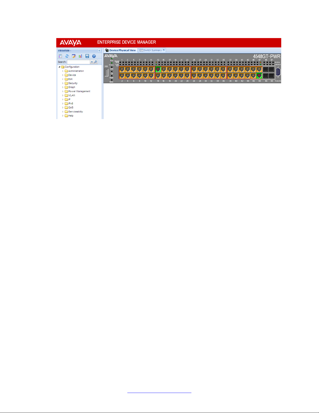
Device Physical View
When you access EDM, the first panel in the work area displays a switch summary view. The
tab behind the summary view is a real-time physical view of the front panel of a device or stack
called the Device Physical View.
Objects in the Device Physical View are
• a stand-alone switch, called a unit
• a switch stack, called a chassis
• a port
From the Device Physical View you can
Enterprise Device Manager concepts
• determine the hardware operating status
• select a switch or a port to perform management tasks on specific objects or view fault,
configuration, and performance information for specific objects
To select an object, click the object. The system outlines the object in yellow, indicating that
the object selected.
The conventions on the device view are similar to the actual switch appearance except that
LEDs in Device Physical View do not blink. The LEDs and the ports are color-coded to reflect
hardware status. Green indicates the port is up and running; red indicates that the port is
disabled.
From the menu bar you can click the Device Physical View tab to open the Device Physical
View any time during a session.
Fundamentals December 2011 27
Page 28
User interface fundamentals
Figure 1: Device Physical View
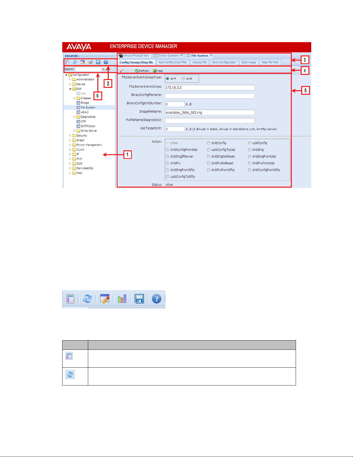
EDM window
The EDM window contains the following parts:
1. navigation tree—the navigation pane on the left side of the window that displays
available command folders in a tree format
2. navigation tree toolbar—the area displays buttons for common functions
3. menu bar—the area at the top of the window that displays primary and secondary
tabs that you accessed during the session; the tabs remain available until you close
them
4. toolbar—the area just below the menu bar that provides quick access to the most
common operational commands such as Apply, Refresh, and Help
5. work area—the main area on the right side of the window that displays the dialog
boxes where you view or configure switch parameters
6. Auto Complete Search — the area between the navigation tree toolbar and the
navigation tree where you can type a partial or complete search string to find menus.
When you type the search string, the navigation tree changes to display only the
entries associated with your search. T o return to the full navigation tree display , click
the x beside the Auto Complete Search dialog box.
28 Fundamentals December 2011
Comments? infodev@avaya.com
Page 29
Enterprise Device Manager concepts
Figure 2: EDM window
Navigation tree
The navigation tree displays available command topics as folders in a tree.
To open a folder or sub-folder, you can click the arrowhead to the left of the folder or double-
click the folder to display the available commands tabs.
To close a folder, click the arrowhead once.
To access a command tab, click the selection in the navigation tree.
Navigation tree toolbar
You can use the toolbar above the navigation tree to perform common functions more easily.
Figure 3: Toolbar
The following is a description of the toolbar button functions:
Button Description
Switch Summary — you can use the Switch Summary toolbar button to open
or reopen the switch summary tab.
Refresh Status — in addition to the existing refresh methods you can use the
Refresh Status toolbar button to refresh the device status
Fundamentals December 2011 29
Page 30
User interface fundamentals
Button Description
Edit Selected — in addition to the existing edit methods, and depending on which
object you select on the Device Physical View , you can use this toolbar button to
open Edit > Chassis, Edit > Unit, or Edit > Ports tabs. If you do not select an
object from the Device Physical View and you click the Edit Select toolbar button,
the Edit > Chassis tab opens.
Graph Selected — depending on which object you select on the Device Physical
View , you can use this toolbar button to open Graph > Chassis or Graph > Port
tabs. If you do not make a selection on the Device Physical View , or if you select
Unit, the Graph > Chassis tab opens.
Save Config — you can use the Save Config toolbar button to save the
configuration to flash memory.
Help Setup Guide — this button connects you to the help setup guide for
embedded EDM and it replaces the link that appeared on the top right of work
panes.
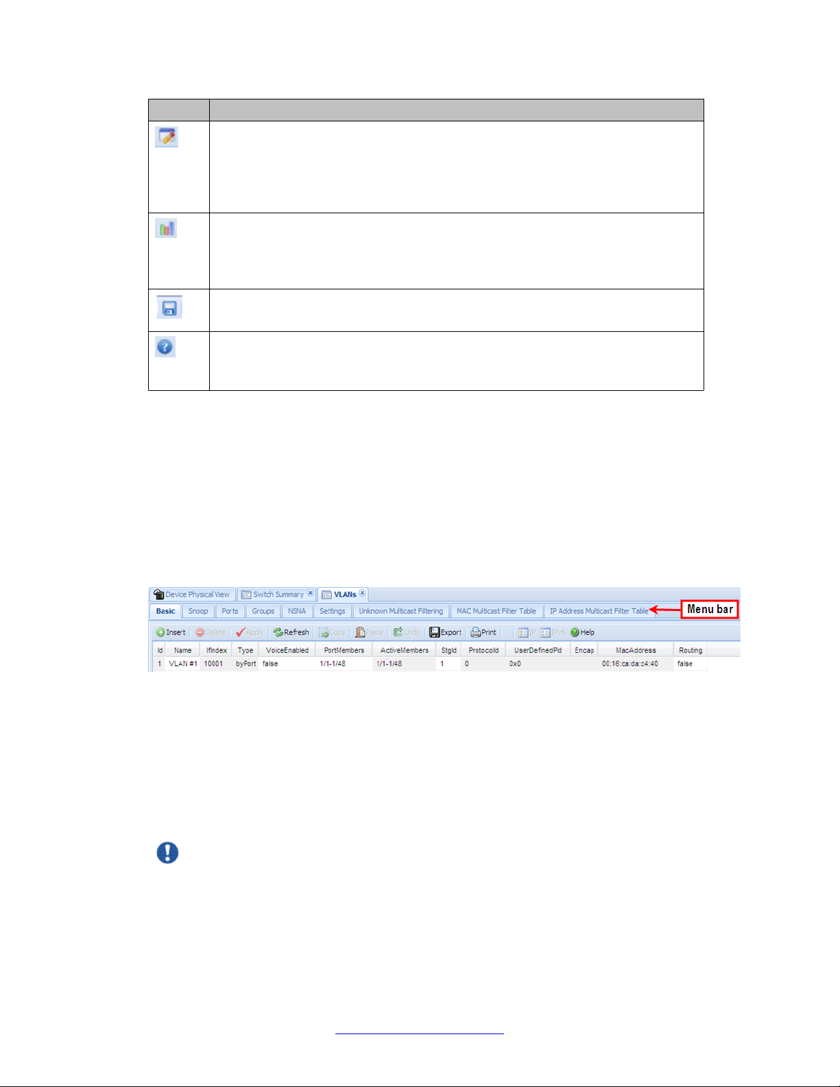
Menu bar
The menu bar appears above the work area and consists of two rows of tabs.
The top row displays tabs that were accessed from the navigation tree during the active
session. The tabs in this row, called primary tabs, are docked and available to reopen on
demand. The docked tabs appear in the sequence that you accessed them.
When you click a primary tab from the menu bar, the associated secondary tabs appear in the
second row and the default dialog box appears in the work area. Click any secondary tab to
display its associated dialog box.
Figure 4: Menu bar
If you want to open a dialog without displacing the current open dialog, you can go to the tab
on the menu bar and undock the tab by using your mouse to drag and drop it into the work
area. You can drag the dialog box to any location on the screen and you can toggle between
the open dialog boxes to compare information and make changes. When you no longer need
the undocked tab, you can use the three buttons on the upper right side of the tab to temporarily
shrink it, re-dock it, or close it.
Important:
When you undock a tab to make changes, and then return to another open tab, in order to
see the effects of the changes you must click the Refresh button on the tool bar.
30 Fundamentals December 2011
Comments? infodev@avaya.com
Page 31

Enterprise Device Manager concepts
In both rows of the menu bar, arrows can appear on the left and right sides when the number
of open tabs exceeds the available space. You can use the arrows to scroll to a tab, or you
can select the tab from the navigation tree.
To reduce the number of open tabs, click the X button on the top right of a tab to close it.
Tool bar
The tool bar, located below the menu bar, contains buttons that provide quick access to
commonly used operational commands. Depending on the tab selected, different buttons can
appear.
Figure 5: Tool bar
The following table describes common tool bar buttons.
Table 2: Common tool bar buttons
Button Name Description
Apply Executes parameter changes.
Refresh Refreshes screen data.
Help Displays context-sensitive online help for the
current dialog box.
Insert Opens an insert dialog box.
Submits the entry from the insert dialog box.
The insert buttons appear only on panes where
you can insert entries.
Delete Removes a selected entry.
Work area
The work area, on the right side of the EDM page, displays the switch Device Physical View
and dialog boxes related to the menu selections in the navigation tree. You can use the work
area to view and configure switch parameters from the dialog boxes that appear in the work
area.
See the following figure for an example of the work area for the Edit > File System > Config/
Image/Diag file dialog.
Fundamentals December 2011 31
Page 32

User interface fundamentals
Figure 6: EDM work area
Single port configuration for EDM
You can apply configuration changes to single ports by using one of the following methods:
• From the Device Physical View, right-click a port and select Edit from the drop-down
menu, and then click the appropriate tab.
The following figure displays the drop-down menu for the selected port in the Device
Physical View.
Figure 7: Device Physical View - port edit
32 Fundamentals December 2011
Comments? infodev@avaya.com
Page 33

Enterprise Device Manager concepts
The following figure displays the port edit work area with the VLAN tab selected.
Figure 8: Port edit -VLAN tab
• From the Device Physical View , click a port, and then from the Navigation tree select any
tab from the Edit > Chassis > Ports work flow, and modify editable parameters.
The following figure displays the Edit > Chassis > Ports work area with the Interface
tab selected.
Figure 9: Edit, Chassis, Ports - Interface tab
• From the Navigation tree select a port-related tab from a specific, applicable feature work
area (for example, VLAN, VLANs, Ports), and double-click a cell under an editable
parameter column heading in the appropriate port row of the table.
The following figure displays the VLAN > VLANs > Ports tab work area.
Fundamentals December 2011 33
Page 34

User interface fundamentals
Figure 10: VLAN, VLANs - Ports tab
Multiple Port Configuration for EDM
When you need to apply the same configuration changes to more than one port, you can use
the Multiple Port Configuration function in any the following ways:
• In the Device Physical View, hold down the Ctrl key and click the ports. Then select the
appropriate tab in the Edit > Chassis > Ports work area to configure the ports.
• In the Device Physical View, hold down the Ctrl key and click the ports you want to
configure. Then right-click and select Edit from the menu.
• In the Device Physical View click and drag to surround a group of related ports. Then
select the appropriate tab in the Edit > Chassis > Ports work area to configure the
ports.
• In the Device Physical View, click and drag to surround a group of related ports. Then
right-click and select Edit from the menu.
The system can generate error messages if you apply a change to all ports when some ports
in the list do not support the change. The error messages provide only the error information
and do not list individual ports.
The following sections use the Edit > Chassis > Ports > Interface tab work area to describe
the available Multiple Port Configuration functions.
34 Fundamentals December 2011
Comments? infodev@avaya.com
Page 35

Enterprise Device Manager concepts
In the work area for any of the Edit > Chassis > Ports tabs, the following two panes appear
in the default view:
• Multiple Port Configuration pane—provides port selection for one port, several ports, or
all ports, and configurable port parameters
• Tab work pane—displays existing configuration information for the feature and
configurable cells for individual ports
With Multiple Port Configuration you can perform the following:
• Hide non-editable fields from the multiple configuration pane so that you choose to view
only those fields that can be configured.
• Select an individual port or a group of ports from the Port Editor.
• Select all ports from the Port Editor, if you are on a feature tab. If you used Edit > Chassis
> Ports you already selected the ports on the Device Physical View.
• Double-click any or all of the editable fields to change the configuration parameter.
• Clear your selections.
• Apply your selections.
• Undo the application of your selections.
You can expand or collapse the Multiple Port Configuration pane by clicking the Multiple Port
Configuration task bar. The Multiple Port Configuration pane is expanded by default.
The following figure displays the tabs available in the Edit > Chassis > Ports work flow, with
the Interface tab selected and the Multiple Port Configuration pane expanded.
Figure 11: Interface tab - Multiple Port Configuration pane expanded
The following figure displays the Edit > Chassis > Ports > Interface tab with the Multiple
Port Configuration pane collapsed.
Fundamentals December 2011 35
Page 36

User interface fundamentals
Figure 12: Interface tab - Multiple Port Configuration pane collapsed
Changes you make to a port configuration using Multiple Port Configuration are applied to the
switch configuration only after you click Apply on the work area toolbar.
The following figure displays the location of the Apply button on the work area toolbar.
Figure 13: Toolbar Apply button
Enterprise Device Manager procedures
About this task
This section contains procedures for starting and using Enterprise Device Manager (EDM) on
your switch. You can use EDM software on the switch; there is no need to install any clientbased application on your PC.
36 Fundamentals December 2011
Comments? infodev@avaya.com
Page 37

Configuring EDM through ACLI
This section describes how to enable and configure the Enterprise Device Manager (EDM)
using ACLI.
Enabling the Web server using ACLI
About this task
The Web server is enabled by default. If you have assigned an IP address to the switch, you
can access EDM.
If you have disabled the Web server you can use the following procedure to enable and manage
the Web server using ACLI. After you enable the Web server, you can start EDM. For more
information about the Web server, see Avaya Ethernet Routing Switch 4000 Configuration –
Security (NN47205-505).
Prerequisites
Enterprise Device Manager procedures
• Open an ACLI session
• Access Global Configuration mode
Procedure
To enable the Web server, enter the following command:
web-server enable
Disabling the Web server using ACLI
About this task
Use the following procedure to disable the Web server using ACLI. After you disable the Web
server, you cannot start EDM.
Prerequisites
• Open an ACLI session
• Access Global Configuration mode
Procedure
To disable the Web server, enter the following command:
no web-server enable
Fundamentals December 2011 37
Page 38

User interface fundamentals
Displaying the Web server status using ACLI
About this task
Use the following procedure to display the Web server status using ACLI.
Prerequisites
• Open an ACLI session
• Access Global Configuration mode
Procedure
To display the Web server status, enter the following command:
show web-server
Variable Definitions
Variable Value
disable Disables HTTP access.
enable Enables HTTP access.
show Shows Web server status.
Starting EDM
To configure and maintain your switch through a Web-based graphical user interface, use the
following procedure to start EDM.
Before you begin
• Ensure that the switch is running.
• Note the switch IP address.
• Ensure that the Web server is enabled.
• Note the user name.
• Note the password.
• Open one of the supported Web browsers.
About this task
Follow these steps to open an EDM session on your switch.
38 Fundamentals December 2011
Comments? infodev@avaya.com
Page 39

Procedure
1. In a supported Web browser, enter the IP address of the switch using one of the
following formats:
http://<IP Address>
•
https://<IP Address>
•
2. Enter the user name.
3. Enter the password.
4. Click Log On.
Using shortcut menus
About this task
In the EDM Device Physical View you can use shortcut menus to edit objects and apply
changes.
Enterprise Device Manager procedures
Procedure
1. In the Device Physical View, select an object.
2. Right-click the object.
3. Select a function from the list.
Variable Definitions
Unit
Edit Displays the Edit unit dialog box and tabs.
Refresh Status Refreshes switch status.
Refresh PoE Status Refreshes the PoE status only to units
Refresh Port Tooltips Refreshes the port tooltip data. Port tooltip
Field
Description
equipped with Power over Ethernet.
data contains: Slot/Port, PortName, and
PortOperSpeed.
Identify Unit Identifies the switch units.
Fundamentals December 2011 39
Page 40

User interface fundamentals
Field Description
Port
Edit Displays the Edit port dialog box and tabs.
Graph Displays the graph port dialog box and
Enable Enables the port administratively.
Disable Shuts down the port administratively.
Opening folders and tabs
The following section describes how to navigate around Enterprise Device Manager (EDM)
and open folders and tabs.
Navigating around EDM
tabs.
About this task
Use the following procedure to navigate around EDM.
Procedure
1. In the navigation pane, click the arrowhead located to the left of a folder to display
2. If there is a sub-folder, double-click the folder or click the arrowhead to open the
3. The primary tabs appear under the folders and sub-folders. Click a tab to open it in
Undocking tabs
About this task
To improve certain types of configuration, you can view more than one tab at a time. To view
more than one tab, you use the undock function to activate a previously-opened tab from the
menu bar.
the sub-level folders in the tree.
sub-folder.
the work area.
Important:
When you undock a tab to make changes, then return to another open tab, in order to see
the effects of the changes you must click the Refresh button on the tool bar.
40 Fundamentals December 2011
Comments? infodev@avaya.com
Page 41

Procedure
1. From the menu bar, drag and drop the tab you want to open.
2. To reposition the tab in the work area, click and drag the title bar of the tab.
Enterprise Device Manager procedures
Docking tabs
About this task
You can re-dock an undocked tab using either of the following methods.
Procedure
Figure 14: Undocking and docking tabs
To re-dock a tab, do one of the following:
• On the undocked tab, click the dock-back button (the middle button on the top
right of the panel).
• On the undocked tab, click the collapse button (left button on the top right of the
panel) to temporarily minimize the panel.
Fundamentals December 2011 41
Page 42

User interface fundamentals
Using dialog boxes
Many EDM dialog boxes contain editable fields where you can enter parameter values.
Some of those parameters have predetermined values. For example, you can enable or disable
a port.
Other parameter values are ranges of values or user-determined values. For example, the
value for the Location on the Base Unit Info tab is a location name you can choose and
enter.
Editable fields in EDM dialog boxes appear in white.
EDM dialog box buttons
The following table describes buttons that appear in the EDM dialog boxes and tabs. Not all
buttons appear in all dialog boxes.
Table 3: EDM dialog box buttons
Button Description
Apply Apply the changes you entered in fields on a tab or dialog box.
The button is unavailable until you change a parameter.
Insert Open a dialog box to create a new entry for a table; then, from
the dialog box, insert the new entry in the table.
Delete Delete a selected entry.
Refresh Refresh the information in the window. Every time you click
Refresh, the switch pools the system and displays new
information.
Close Close the tab or dialog box and disregard changes you made
to fields.
Help Open context-sensitive Online Help.
Stop Stop the current action.
Copy Copy selected items to your computer memory clipboard.
Paste Paste the contents of your computer clipboard.
Undo Undo last action.
Export Copy data to external media.
Print Print the contents of any displayed table.
Graph Graph selected data.
42 Fundamentals December 2011
Comments? infodev@avaya.com
Page 43

Enterprise Device Manager procedures
Button Description
Export (on Graph dialog
boxes)
Clear Counters Clear the existing number of counters and restart the
Clear all Clear the numbers of all statistics and restart the count.
Editing a dialog box
About this task
Use the following procedure to edit a dialog box.
Procedure
1. In the work area, double-click the field you want to edit.
2. Select a value from the list of predetermined values or enter the value for a field
without preset values.
Enter an IP address in decimal format: <xxx>.<xxx>.<xxx>.<xxx>.
Save the current table in ASCII format in a file you specify. The
table contains tabs that you can use to import this file into a
text editor or spreadsheet for further analysis.
counters.
Important:
Enter a MAC address in hexadecimal format: xx:xx:xx:xx:xx:xx.
Time is a value based on the delta from the switch boot-up time.
3. Click Apply.
Inserting an entry in a dialog box
About this task
Use the following procedure to insert an entry in a dialog box.
Procedure
1. On the tool bar, click Insert .
2. Enter changes in the Insert dialog box.
3. Click Insert to submit the entry and return to the active tab in the work area.
4. On the toolbar, click Apply to commit the change to the configuration. The system
refreshes the view and errors display in a browser popup.
Fundamentals December 2011 43
Page 44

User interface fundamentals
Deleting an entry from a dialog box
About this task
Use the following procedure to delete an entry from a dialog box.
Procedure
1. Highlight the entry.
2. Click Delete.
Editing objects
Y ou can edit objects in the Device Physical View from the navigation tree or the shortcut menu.
Changes are not applied to the running configuration until you click Apply.
Editing an object using the shortcut menu
About this task
Use the following procedure to edit an object using the shortcut menu.
Procedure
1. On the Device Physical View, you can
• right click an object
• press Ctrl+click to select several objects; then right click
• click and drag to select a group of objects; then right click
• click an entire device; then right click
2. From the list, click Edit.
3. Edit the applicable tab in the work area.
4. Click Apply.
Editing file system elements
About this task
Use the procedure and job aid in this section to edit file system elements.
44 Fundamentals December 2011
Comments? infodev@avaya.com
Page 45

Procedure
1. Click the Edit arrowhead to open the Edit menu.
2. Click File System to open the File System tab in the work area. For further
information about configuration files and licensing, see Configuration files
fundamentals on page 55 and Feature licensing fundamentals on page 13.
Job aid, tabs in the File System work area
Tab Description
Config/Image/Diag file Use this tab to view information about and
Ascii Config File Use this tab to acquire ASCII configuration
License File Use this tab to view and manage software
Enterprise Device Manager procedures
acquire image, configuration, and firmware
files.
files.
licensing.
Save Configuration Use this tab to save the current configuration
manually or automatically.
Boot Image Use this tab to view information about
software and diagnostics images loaded on
your switch.
Help File Path Use this tab to designate the file path to the
EDM help files. You can use a USB mass
storage device or a TFTP server.
Job aid, folders and subfolders in the navigation tree
Folder Description
Administration Use the tabs associated with the sub-folders
in the Administration folder to perform the
following functions:
• Quick Start –set up IP/Community/Vlan
and Trap Receiver
• Remote Access – enable or disable T elnet,
SNMP, Web Page, and SSH
• MIB Web Page – perform a MIB Walk
Device Rediscover Device— Use the Rediscover
Device selection to refresh the session.
Caution: all existing tabs are lost.
Edit Use the tabs associated with the sub-folders
in the Edit folder to view or change
Fundamentals December 2011 45
Page 46

User interface fundamentals
Folder Description
parameters for the currently-selected
object.
Sub-folders in the Edit folder are:
• Unit
• Chassis: Chassis, Switch/Stack, Ports,
and Environment
• Bridge
• File System
• ADAC
• Diagnostics: Port Mirrors, Topology,
System Log. 802.1AB: LLDP, Port dot1,
Port dot3, Port MED, Avaya
• NTP
• SNTP/Clock
• Snmp Server: MIB View , User, Community ,
Host, Notification Control
Security Use the tabs associated with the sub-folders
in the Security folder to view or change
security settings.
Sub-folders in the Security folder are:
• MAC Security
• DHCP Snooping
• Dynamic ARP Inspection (DAI)
• IP Source Guard (IPSG)
• 802.1X/EAP
• Web/Telnet/Console
• SSH/SSL
• RADIUS
• NSNA
• TACACS+
Graph Use the tabs associated with the sub-folders
in the Graph folder to view statistics and
produce graphs of the statistics.
Sub-folders in the Graph folder are:
46 Fundamentals December 2011
Comments? infodev@avaya.com
Page 47

Enterprise Device Manager procedures
Folder Description
• Chassis
• Port —to view or graph statistics for a port,
first select a port on the Device Physical
View.
Power Management Use the tabs associated with the sub-folders
in the Power Management folder to view and
configure Power over Ethernet (PoE)
settings and to view and configure Energy
Saver settings.
Sub-folders in the Power Management folder
are:
• PoE
• Energy Saver
PoE is only available for switches equipped
with Power over Ethernet.
VLAN Use the tabs associated with the sub-folders
in the VLAN folder to configure or view
information about VLANs, Spanning Tree,
and Multi-Link Trunking.
Sub-folders in the VLANs folder are:
• VLANs
• Spanning Tree: Globals, STG, RSTP,
MSTP
• MLT/LACP
• SLPP
IP Use the tabs associated with the sub-folders
in the IP folder to configure IP routing
functions.
Sub-folders in the IP folder are:
• IP
• TCP/UDP
• OSPF
• RIP
• VRRP
• IGMP
• DHCP Relay
• UDP Forwarding
• Policy
Fundamentals December 2011 47
Page 48

User interface fundamentals
IPv6 Use the tabs associated with the sub-folders
QoS Use the tabs associated with the sub-folders
Folder Description
in the IPv6 folder to set up IPv6 routing
functions.
Sub-folders in the IPv6 folder are:
• IPv6
• TCP/UDP
in the QoS folder to configure quality of
service and set up QoS policies and filters.
Sub-folders in the QoS folder are:
• QoS Devices
• QoS Rules
• QoS
• QoS Agent
• QoS NSNA/Traffic Profile
Serviceability Use the tabs associated with the sub-folders
in the Serviceability folder to monitor traffic
flows using IPFIX, and to monitor and
configure remote monitoring.
Sub-folders in the Serviceability folder are:
• IPFIX
• RMON: Alarms, Control
Help Use the tabs associated with the sub-folders
in the Help folder to access help and support
for the following:
• Device Manager Basic
• Support Portal (Avaya)
• Support Portal (Nortel Legacy)
• Legend : Up, Down, No Link, Standby,
Testing, Unmanageable, and Loopback.
Example 1 - Configuring multiple Interface ports using EDM
About this task
The following procedure provides sample steps for configuring multiple interface ports using
the Multiple Port Configuration function and the Edit > Chassis > Ports > Interface work flow.
When you use this work flow you must first select ports on the Device Physical View.
48 Fundamentals December 2011
Comments? infodev@avaya.com
Page 49

Procedure
1. On the Device Physical View, select a port or ports.
2. From the navigation tree, double click Edit.
3. From the Edit tree, double click Chassis.
4. From the Chassis tree, click Ports.
5. Click the Interface tab.
6. To change the configuration of the selected ports, in the Multiple Port Configuration
7. In the Make Selection pane, click Apply Selection.
8. On the Interface tab toolbar, click Apply to apply the changes to the switch
Enterprise Device Manager procedures
pane, double-click the cell beneath the column heading that represents the
parameter you want to change and do one of the following:
• Select a value from a drop-down list.
• Type a value in the cell.
The changes appear in the table.
configuration.
Example 2 — Configuring multiple ports using EDM
The following procedure provides sample steps for configuring multiple ports using the Multiple
Port Configuration function and the Security > MAC Security > AutoLearn workflow. When
you use this, and similar workflows, you can select ports directly from the Multiple Port
Configuration pane on the configuration tab. If you use the Edit > Chassis > Ports workflows
you must first select ports on the Device Physical View.
Procedure steps
1. From the navigation tree, double click Security.
2. From the Security tree, click MAC Security.
3. Click the AutoLearn tab.
4. In the work area, in the Make Selection section of the Multiple Port Configuration
pane, click the Switch/Stack/Ports ellipsis (...) to open the Port Editor dialog.
5. In the Port Editor window, click the ports you want to configure.
Note:
If you want to configure all ports, click All.
6. Click OK to return to the Make Selection pane.
The ports you selected appear in the Switch/Stack/Ports box.
Fundamentals December 2011 49
Page 50

User interface fundamentals
7. To change the configuration of the selected ports, in the Multiple Port Configuration
pane, double-click the cell beneath the column heading that represents the
parameter you want to change and do one of the following:
• Select a value from a drop-down list.
• Type a value in the cell.
8. In the Make Selection pane, click Apply Selection.
The changes appear in the table.
9. On the AutoLearn tab toolbar, click Apply to apply the changes to the
configuration.
Job aid, buttons and dialogs on the Multiple Port Configuration pane
Button or dialog
name
Switch/Stack/Ports: Opens the Port Editor
Port Editor Provides a list of all ports on
Apply Selection Applies port selections and
Button or dialog Description
dialog.
the switch or stack.
• Click OK to accept port
selections and return to
the Multiple Port
Configuration pane.
• Click Cancel to return to
the Multiple Port
Configuration pane.
• Click All to select all ports
and return to the Multiple
Port Configuration pane.
parameter changes to the
Multiple Port Configuration
pane and the port data table
for review.
Clear Selection Clears Multiple Port
Configuration selections.
Undo Apply Deletes port changes
applied in the Multiple Port
Configuration pane.
Hide Non-Editable Displays only those
parameters that are
editable in the Multiple Port
Configuration pane for the
selected ports.
50 Fundamentals December 2011
Comments? infodev@avaya.com
Page 51

Graphing statistics
About this task
You can graph statistics for an entire device, a group of ports, or a single port.
Procedure
1. On the Device Physical View select one of the following:
• a port
• a group of ports
• a device
2. In the navigation tree, double-click Graph.
3. In the Graph tree select one of the following:
• Chassis
• Port
Enterprise Device Manager procedures
4. On the work area, select a tab.
5. On the tab, select information to graph. To export the information to another
application, on the task bar click Export Data.
6. To create the graph, on the task bar, click a graph type.
Getting EDM online help files for embedded EDM
Because help files are not included with the embedded EDM software files on the switch, you
need to download the help files to a TFTP destination and use ACLI to configure a path from
your switch to the help files. You can also use a USB mass storage device to contain help files
for switches equipped with a USB port.
If you are using COM to manage your switch, help resides with COM and you do not need to
use these procedures.
Downloading help files
About this task
Use the following procedure to download help files.
Fundamentals December 2011 51
Page 52

User interface fundamentals
Prerequisites
• An available TFTP server— ensure that the TFTP path differs from the path you use to
download switch software, or
• A USB mass storage device and switch equipped with a USB port
Caution:
Do not install EDM help files on PCMCIA or Flash.
Procedure
1. To obtain EDM help files for the embedded element manager, do one of the
following:
2. Do one of the following:
• Go to the Avaya Web site http://support.avaya.com and locate the help files
for the appropriate product.
• Select the help file from the software CD ROM.
• Download the help file to a TFTP server.
• Download the help file to a USB mass storage device.
3. Unzip the help file in the TFTP server directory.
Configuring the path to the help files using ACLI
About this task
Use the following procedure to configure the path to the help files.
Procedure
1. Open an ACLI session.
2. Enter the Global Configuration mode.
3. At the command prompt, enter the following ACLI command:
edm help-file-path <path name> <tftp address | usb>
<filename>
Variable Definitions
Field
path name Specifies the path name you created for
EDM help files. The path name is stored in
NVRAM.
52 Fundamentals December 2011
Comments? infodev@avaya.com
Description
Page 53

Field Description
TFTP address Specifies EDM TFTP server IP address.
Use this address only for EDM help files.
If you do not specify a TFTP server address,
the system uses the address specified most
recently.
usb <unit> Specifies the unit number where the USB
mass storage device that contains the help
files resides. The unit number is an integer
from 1–8.
Configuring the help file path using EDM
Enterprise Device Manager procedures
Warning:
Because the TFTP server address is
stored in NVRAM, each time the system
returns to the default configuration, you
must reconfigure the path to EDM online
help.
About this task
Use the following procedure to configure the path to the help files.
Procedure
1. In the navigation tree, double-click Edit or click the Edit arrowhead to open the Edit
menu.
2. Click File System to open the File System work area.
3. In the work area, click the Help File Path tab.
4. In the Help TFTP Source Directory Path field, enter the path to the help file storage
location; examples, tftp://aaa.bbb.ccc.ddd/file_name, usb://file_name, or usb://unit
number/file_name.
Fundamentals December 2011 53
Page 54

User interface fundamentals
54 Fundamentals December 2011
Comments? infodev@avaya.com
Page 55

Chapter 4: Configuration files
fundamentals
This chapter provides fundamental information about working with configuration files.
Configuration files are ASCII text files that allow the administrator to change switch configuration
quickly.
Procedures to manage binary configuration files are included in the Enterprise Device Manager section.
Procedures for Universal Serial Bus (USB) devices apply only to switch models with USB ports.
ACLI configuration files
You can use ACLI to display, store, and retrieve configuration files, and to save the current
configuration.
Configuration file management procedures
About this task
Perform the procedures in this section to display, store, restore, and save configuration files
using ACLI. For more information about command variables, see ACLI command job aids on
page 58.
Viewing current configuration using ACLI
Procedure
1. At the command prompt, enter enable to enter the Privileged EXEC ACLI mode.
2. At the prompt, enter show running-config.
Fundamentals December 2011 55
Page 56

Configuration files fundamentals
Saving current configuration to SFTP server using ACLI
Procedure
1. At the command prompt, enter enable to enter the Privileged EXEC ACLI mode.
2. At the prompt, enter copy running-config sftp [verbose] [module
<applicationModules>] [filename <WORD>] ([address {<A.B.C.D>
| <ipv6addr>}]) username <WORD> [password].
Saving current configuration to TFTP server using ACLI
Procedure
1. At the command prompt, enter enable to enter the Privileged EXEC ACLI mode
2. At the prompt, enter copy running-config tftp [address {<A.B.C.D> |
<WORD>}] [module <applicationModules>][filename <WORD>]
[verbose]
Saving current configuration to USB device using ACLI
Procedure
1. At the command prompt, enter enable to enter the Privileged EXEC ACLI mode
2. At the prompt, enter copy running-config usb [filename <WORD>]
[module <applicationModules>][unit<1–8>] [verbose]
Saving current configuration to flash memory using ACLI
Procedure
1. At the command prompt, enter enable to enter the Privileged EXEC ACLI mode.
2. At the prompt, enter copy config nvram.
56 Fundamentals December 2011
Comments? infodev@avaya.com
Page 57

Restoring system configuration from USB device using ACLI
Procedure
1. At the command prompt, enter enable to enter the Priviliged EXEC ACLI mode.
2. At the prompt, enter copy config usb {filename <name> | unit
<1-8>}.
Restoring system configuration from TFTP using ACLI
Procedure
1. At the command prompt, enter enable to enter the Priviliged EXEC ACLI mode.
2. At the prompt, enter copy tftp config address <A.B.C.D> | <WORD>
filename <name>.
ACLI configuration files
Restoring system configuration from SFTP using ACLI
Procedure
1. At the command prompt, enter enable to enter the Priviliged EXEC ACLI mode.
2. At the prompt, enter copy sftp config address <A.B.C.D> | <WORD>
filename <name> username <WORD>[password].
Copying stack unit configuration to standalone switch using ACLI
Procedure
1. At the command prompt, enter enable to enter the Privileged EXEC ACLI mode.
2. At the prompt, enter copy [ tftp | sftp ] config address <A.B.D.C>
| <WORD> filename <name> unit <unit number>.
Fundamentals December 2011 57
Page 58

Configuration files fundamentals
Downloading a configuration file automatically using ACLI
Procedure
1. Access the Privileged EXEC ACLI mode.
2. Enter the configure network load-on-boot {disable | use-bootp |
use-config} address <A.B.C.D> | <ipv6_address> filename
<name> command to configure a switch or stack to automatically load a
configuration file.
ACLI command job aids
The following table describes the copy running-config command variables.
Variable Definition
{tftp | sftp | usb} Specifies whether to save the file to a TFTP
or SFTP server or a USB mass storage
device.
Note:
Not all switch models have a USB port.
address <A.B.C.D> | <WORD> Specifies the address of the TFTP or SFTP
server.
• A.B.C.D—specifies the IP address
• WORD—specifies the IPv6 address
filename <name> Specifies the configuration file name.
username <WORD> Specifies the username for downloading a
configuration file automatically using ACLI.
[password] Specifies the password for downloading a
configuration file automatically using ACLI.
The following table describes the copy config tftp unit command variables.
Variable Definition
address <A.B.C.D> | <WORD> Specifies the address of the TFTP or SFTP
server.
• A.B.C.D—specifies the IP address
• WORD—specifies the IPv6 address
58 Fundamentals December 2011
Comments? infodev@avaya.com
Page 59

ACLI configuration files
Variable Definition
filename <name> Specifies the configuration file name.
unit <unit number> Specifies the stack unit number.
The following table describes the configure network load-on-boot command
variables.
Variable Definition
load-on-boot {disable | use-bootp | useconfig}
Viewing USB files
About this task
You can display configuration files stored on a USB device in a unit in a stack. From the ACLI
Privileged EXEC mode, enter the following command: show usb-files
Following is an output example for the show usb-files command:
Specifies the setting to automatically load a
configuration file when the system starts
disable disables the automatic loading of the
configuration file. use-bootp specifies
loading the ASCII configuration file at startup
and using BootP to obtain values for the
TFTP or SFTP address and file name. use-
config specifies loading the ASCII
configuration file at startup and using the
locally configured values for the TFTP or
SFTP address and file name. If you omit the
variables, the system immediately
downloads and runs the ASCII configuration
file.
ERS4000#show usb-files
USB file list - Stand-alone
Listing Directory USB_BULK:
657 Feb 17 2009 IP.CFG
6217432 Mar 3 2009 4000_53044.img
1589514 Feb 25 2009 4000_5303.bin
2048 Mar 4 2009 ABC/
Viewing USB host port information
About this task
You can display the USB host port information for a unit in a stack. From the ACLI Privileged
EXEC mode, enter the following command:
show usb-host-port [unit <1–8>]
Fundamentals December 2011 59
Page 60

Configuration files fundamentals
Following is an output example for the show usb-host-port command:
ERS4850GTS(config)#show usb-host-port
USB Host Port Info - Stand-alone Enabled
--------------------------------------- Vendor Info : Imation
Product ID : Flash Drive
Product Revision : 1.00
Number of Blocks : 1974271
Bytes per Block : 512
Total Capacity : 1010826752
Enterprise Device Manager configuration files
This section describes how to use Enterprise Device Manager (EDM) to store and retrieve
configuration files.
Using EDM, you can store the current ASCII switch configuration file on a TFTP or SFTP server
or a USB storage device, retrieve an ASCII configuration file from a TFTP or SFTP server or
USB storage device to apply to a switch, store or retrieve a binary configuration file, or manually
save the current configuration to flash memory.
You can check file upload transfer status of ASCII configuration files in the
ScriptLastStatusChange field on the Edit > File System > Ascii Config Script Files tab.
During upload transfer, the status is manualUploadInProgress. To check changes to file
transfer status, click Refresh. After the file transfer is complete the status displays as either
manualUploadPassed or manualUploadFailed.
You can check file download transfer status of ASCII configuration files in the
ScriptLastStatusChange field on the Ascii Config Script Files tab. During download transfer,
the status is manualDownloadInProgress. To check changes to file transfer status, click
Refresh. After the file transfer is complete, the status displays as either
manualDownloadPassed or manualDownloadFailed.
You can also designate an ASCII configuration file to download automatically at switch
startup.
To control which ASCII configuration files load automatically, at switch startup, use the fields
in the table on the Edit > File System > Ascii Config Script Files.
The Ascii Config Script Files table provides a way to control which ASCII configuration files
are loaded, and in which order, because you can designate the path to an ASCII configuration
file, a boot priority value, and a script index priority for each entry in the table.
60 Fundamentals December 2011
Comments? infodev@avaya.com
Page 61

Enterprise Device Manager configuration files
Depending on which script source you designate for an entry , the system uses the designated
paths in the Ascii Config Script Files table in one of the following ways:
• The system uses BootP to download the designated ASCII configuration file from the
network, according to the specified IP address and file name.
• The system downloads the designated ASCII configuration file from a TFTP or SFTP
server, according to the specified IP address and file name.
• The system downloads the ASCII configuration file from a USB device, according to the
specified file name.
In the boot priority column on the Ascii Config Script Files tab, if you designate a non-zero boot
priority value for any but the first row, the switch attempts to load the configuration file at startup.
The first entry in the configuration files table is assigned a fixed boot priority value of 0 and it
is not available to load at startup.
The switch attempts to load each ASCII configuration file with a non-zero priority value, in
ascending order, until a script file loads successfully. If ASCII configuration file boot priority
values are equal, the switch attempts to load the configuration files according to their script
index order.
In the Script Source column on the Ascii Config Script Files table, if you designate a USB device
in a standalone switch as the load-on-boot path to the ASCII configuration file, the switch
downloads the specified configuration file from the USB port of the switch. If you designate a
USB device in a stack unit as the load-on-boot path to the ASCII configuration file entry, the
system downloads the specified configuration file from the USB port of the designated unit or,
if no unit is designated, from the USB port of the base unit. If the system cannot download the
configuration file, or if the script does not execute successfully, the script operational status
changes to autoDownloadFailed and the system downloads the next entry in the table.
When the configuration file downloads and executes without errors, the operational status for
the entry changes to autoDownloadPassed.
ASCII and binary configuration file procedures
About this task
Perform the procedures in this section to use EDM to manage ASCII and binary configuration
files. For more information about fields on the Config/ImageDiag file tab, used to manage binary
configuration files, see Config/Image/Diag file tab field descriptions job aid on page 67.
Procedures for USB devices apply only to switch models equipped with USB ports.
Fundamentals December 2011 61
Page 62

Configuration files fundamentals
Storing current ASCII configuration on a TFTP server using EDM
Procedure
1. From the navigation tree, double-click Edit to open the Edit tree.
2. Click File System.
3. Click the Ascii Config Script Files tab.
4. Double-click the ScriptSource field and type the TFTP server address and the
configuration file name in this format: tftp://<ip address>/<filename>. The
entry is limited to a maximum of 327 characters.
5. Double click the ScriptManual field and then choose Upload from the list.
6. On the toolbar, click Apply.
Storing current ASCII configuration on a SFTP server using EDM
Procedure
1. From the navigation tree, double-click Edit to open the Edit tree.
2. Click File System.
3. Click the Ascii Config Script Files tab.
4. Double-click the ScriptSource field and type the SFTP server address and the
configuration file name in this format: sftp://<ip address>/<filename>. The
entry is limited to a maximum of 327 characters.
5. Double click the ScriptManual field and then choose Upload from the list.
6. On the toolbar, click Apply.
Storing current ASCII configuration on a USB device using EDM
Procedure
1. From the navigation tree, double-click Edit to open the Edit tree.
2. Click File System.
3. Click the Ascii Config Script Files tab.
4. Double-click the ScriptSource field and type usb://<filename> to store the
configuration file on a USB device in a stand-alone unit or usb://<unit
62 Fundamentals December 2011
Comments? infodev@avaya.com
Page 63

Enterprise Device Manager configuration files
number>/<filename> to store the configuration file on a USB device in a unit in
a stack.
5. Double-click the ScriptManual field and then choose Upload from the list.
6. On the toolbar, click Apply.
Downloading an ASCII Configuration from a TFTP server using EDM
Procedure
1. From the navigation tree, double-click Edit to open the Edit tree.
2. Click File System.
3. Click the Ascii Config Script Files tab.
4. Double-click the ScriptSource field and type the TFTP server IP address and
configuration file name in the following format: tftp://<ip address>/
<filename>.
5. Double-click the ScriptManual field and then select Download from the list.
6. On the toolbar, click Apply.
Downloading an ASCII configuration from a SFTP server using EDM
Procedure
1. From the navigation tree, double-click Edit to open the Edit tree.
2. Click File System.
3. Click the Ascii Config Script Files tab.
4. Double-click the ScriptSource field and type the SFTP server IP address and
configuration file name in the following format: sftp://<ip address>/
<filename>.
5. Double-click the ScriptManual field and then select Download from the list.
6. On the toolbar, click Apply.
Fundamentals December 2011 63
Page 64

Configuration files fundamentals
Downloading an ASCII configuration from a USB device using EDM
Procedure
1. From the navigation tree, double-click Edit to open the Edit tree.
2. Click File System.
3. Click the Ascii Config Script Files tab.
4. Double-click the ScriptSource field and type the configuration file name in the
following format: usb://<filename> for a USB device in a standalone unit or
usb://<unit number>/<filename> for a USB device in a unit in a stack.
5. Double-click the ScriptManual field, and then select Download from the list.
6. On the toolbar, click Apply.
Downloading a configuration file automatically using EDM
Procedure
1. From the navigation tree, double-click Edit.
2. Click File System.
3. Click the Ascii Config Script Files tab.
4. Double-click the ScriptSource field and type the TFTP server IP address and the
configuration file name in the following format: tftp://<ip address>/
<filename>. Substitute usb://<filename> to retrieve a configuration from a
USB device in a stand-alone unit or usb://<unit number>/<filename> if the
USB device resides in a unit in a stack. If you retrieve the configuration file from a
BOOTP server, type bootp:// in the ScriptSource field.
5. Double-click the ScriptBootPriortity field and type a digit between 1 and 127 for
the script priority; use 0 if you are not using the entry at startup.
6. On the toolbar, click Apply.
64 Fundamentals December 2011
Comments? infodev@avaya.com
Page 65

Enterprise Device Manager configuration files
Storing a binary configuration file on a TFTP server using EDM
Procedure
1. From the navigation tree, double-click Edit.
2. Click File System.
3. Click the Config/Image/Diag file tab.
4. In the TftpServerInetAddressType dialog, click the applicable address type
button.
5. In the TftpServerInetAddress field, enter the TFTP server IP address.
6. In the BinaryConfigFilename field, enter the configuration file name.
7. In the BinaryConfigUnitNumber field enter the stack unit number or, for a standalone switch, enter 0.
8. In the Action box, select upldConfig.
9. On the toolbar, click Apply.
Storing a binary configuration file on a USB device using EDM
Procedure
1. From the navigation tree, double-click Edit .
2. Click File System.
3. Click the Config/Image/Diag file tab.
4. In the BinaryConfigFilename field, enter the configuration file name.
5. In the BinaryConfigUnitNumber field enter the stack unit number or, for a standalone switch, enter 0.
6. In the UsbTargetUnit field, enter the stack number where the USB device is
inserted.
7. In the Action box, click the upldConfigtoUsb button.
8. On the toolbar, click Apply.
Fundamentals December 2011 65
Page 66

Configuration files fundamentals
Downloading a binary configuration file from a TFTP server using EDM
Procedure
1. From the navigation tree, double-click Edit .
2. Click File System.
3. Click the Config/Image/Diag file tab.
4. In the TftpServerInetAddress field, enter the TFTP server IP address.
5. In the BinaryConfigFilename field, enter the configuration file name.
6. In the BinaryConfigUnitNumber field, enter the stack unit number or, for a standalone switch, enter 0.
7. In the Action field, click the dnldConfig button.
8. On the toolbar, click Apply.
Downloading a binary configuration file from a USB device using EDM
Procedure
1. From the navigation tree, double-click Edit .
2. Click File System.
3. Click the Config/Image/Diag file tab.
4. In the BinaryConfigFilename field, enter the configuration file name.
5. In the BinaryConfigUnitNumber field, enter the stack unit number or, for a standalone switch, enter 0.
6. In the UsbTargetUnit field, enter the stack unit number where the USB resides.
7. In the Action field, click the dnldConfigFromUsb button.
8. On the toolbar, click Apply.
Saving current configuration to flash memory manually using EDM
Procedure
1. From the navigation tree, double-click Edit.
2. Click File System.
66 Fundamentals December 2011
Comments? infodev@avaya.com
Page 67

Enterprise Device Manager configuration files
3. Click the Save Configuration tab.
4. Ensure that the AutosavetoNvramEnabled box is not checked.
5. In the Action field, click the copyConfigToNvram button.
6. On the toolbar, click Apply.
7. On the toolbar, click Refresh to check progress.
Config/Image/Diag file tab field descriptions job aid
For more information about fields on the Config/Image/Diag file tab, see the following table.
Field name Description
TftpServerInetAddressType Specifies the IP version of the TFTP server address
TftpServerInetAddress Specifies the TFTP server IP address
BinaryConfigFilename Specifies the name of the binary configuration file
BinaryConfigUnitNumber Specifies the unit number of a switch in a stack
ImageFileName Specifies the software image file name
FWFileName(Diagnostics) Specifies the diagnostics file name
USBTargetUnit Specifies the unit number containing the USB port
Action
• dnldConfigFromUSB—download a configuration
to the switch from a USB device.
• DnldImgIfNewer—download a new software
image to the switch only if it is newer than the current
image.
• dnldFw—download a new diagnostic software
image to the switch.
• dnldConfig—download a configuration file to the
switch.
• upldConfigToUsb—upload a configuration file to a
USB device.
• dnldImgNoReset—download a new software
image to the switch without a switch reset.
• dnldFwNoReset—download a new diagnostic
software image to the switch without a switch
reset.
• upldConfig—upload a configuration file to the
switch from a designated location.
Fundamentals December 2011 67
Page 68

Configuration files fundamentals
Field name Description
• dnldImg—download a new software image to the
switch.
• dnldImgFromUsb—download a new software
image to the switch from a USB device.
• dnldFwFromUsb—download a new diagnostic
software image to the switch from a USB device.
• dnldImgFromSftp—downloads a new software
image to the switch from the SFTP server. This
option replaces the software image on the switch
regardless of whether it is newer or older than the
current image.
• dnldFwFromSftp—downloads a new diagnostic
software image to the switch from the SFTP server .
This option replaces the image regardless of
whether it is newer or older than the current
image.
• dnldConfigFromSftp—downloads a configuration
to the switch from the SFTP server.
• upldConfigToSftp—uploads a configuration to the
SFTP server.
Status Displays the status of the most recent action since last
switch restart.
68 Fundamentals December 2011
Comments? infodev@avaya.com
Page 69

Chapter 5: Supported standards and
Request for comments
Use this chapter as a quick reference of standards and RFCs supported by the switch.
Standards
The standards in the following list are supported on the switch:
• IEEE 802.1X (EAPOL)
• IEEE 802.3 (Ethernet)
• IEEE 802.3u (Fast Ethernet)
• IEEE 802.3x (Flow Control)
• IEEE 802.3z (Gigabit Ethernet)
• IEEE 802.3ab (Gigabit Ethernet over Copper)
RFCs
• IEEE 802.3ad (Link Aggregation)
• IEEE 802.1ab (Link Layer Discovery Protocol)
• IEEE 802.1p (Prioritizing)
• IEEE 802.1D (Spanning Tree Protocol)
• IEEE 802.1Q (VLAN Tagging)
For more information about networking concepts, protocols, and topologies, consult the
following RFCs:
• RFC 826 (ARP)
• RFC 951 (BootP)
• RFC 2131 (BootP/DHCP Relay Agent)
• RFC 1493 (Bridge MIB)
• RFC 4541 (Considerations for Internet Group Management Protocol (IGMP) and
Multicast Listener Discovery (MLD) Snooping Switches)
Fundamentals December 2011 69
Page 70

Supported standards and Request for comments
• RFC 3046 (DHCP Relay Agent Information Option)
• RFC 3993 (DHCP Subscriber-ID suboption)
• RFC 2474 (Diffserv)
• RFC 2475 (Diffserv)
• RFC 2737 (Entity MIBv2)
• RFC 2665 (Ethernet MIB)
• RFC 3246 (Expediting Forwarding)
• RFC 1945 (HTTP v1.0)
• RFC 792 (ICMP)
• RFC 1112 (IGMPv1)
• RFC 2236 (IGMPv2)
• RFC 3376 (Internet Group Management Protocol, Version 3)
• RFC 2863 (Interfaces Group MIB)
• RFC 2933 (Internet Group Management Protocol MIB)
• RFC 2715 (Interoperability Rules for Multicast Routing Protocols)
• RFC 791 (IP)
• RFC 4293 (IPv6)
• RFC 3917 (IP Flow Information Export (IPFix))
• RFC 894 (IP over Ethernet)
• RFC 1213 (MIB-II)
• RFC 3954 (Netflow Services Export v9)
• RFC 1305 (Network Time Protocol Version 3)
• RFC 5905 (Network Time Protocol Version 4)
• RFC 1583 (OSPF v2)
• RFC 1850 (OSPF v2 MIB)
• RFC 2328 (OSPF v2)
• RFC 2674 (Q-BRIDGE-MIB)
• RFC 1757 (RMON)
• RFC 2865 (RADIUS)
• RFC 3576 (RADIUS)
• RFC 2866 (RADIUS Accounting)
• RFC 4673 (RADIUS Dynamic Authorization Server MIB)
• RFC 1058 (RIP v1)
• RFC 2453 (RIP v2)
70 Fundamentals December 2011
Comments? infodev@avaya.com
Page 71

• RFC 1271 (RMON
• RFC 2819 (RMON MIB)
• RFC 4250 (The Secure Shell [SSH] Protocol Assigned Numbers)
• RFC 4251 (The Secure Shell [SSH] Protocol Architecture)
• RFC 4252 (The Secure Shell [SSH] Authentication Protocol)
• RFC 4253 (The Secure Shell [SSH] Transport Layer Protocol) -
• RFC 4254 (The Secure Shell [SSH] Connection Protocol)
• RFC 1157 (SNMP)
• RFC 3411 (SNMP Frameworks)
• RFC 3412 (SNMP Message Processing)
• RFC 3410 (SNMPv3)
• RFC 3413 (SNMPv3 Applications)
• RFC 3414 (SNMPv3 USM)
• RFC 3415 (SNMPv3 VACM)
RFCs
• RFC 3569 (An Overview of Source-Specific Multicast [SSM])
• RFC 854 (Telnet)
• RFC 793 (TCP)
• RFC 4022 (TCP MIB)
• RFC 1350 (TFTP)
• RFC 768 (UDP)
• RFC 4113 (UDP MIB)
• RFC 4604 (Using Internet Group Management Protocol Version 3 [IGMPv3])
• RFC 3768 (Virtual Router Redundancy Protocol)
Fundamentals December 2011 71
Page 72

Supported standards and Request for comments
72 Fundamentals December 2011
Comments? infodev@avaya.com
Page 73

Chapter 6: ACLI quick reference
This chapter provides a quick reference for frequently used ACLI tasks.
For more information about using ACLI, see User interface fundamentals on page 19.
For more information about detailed configuration, see the function-specific configuration documents for
this product. For the list of documents, see Avaya Ethernet Routing Switch 4000 Series Documentation
Roadmap (NN47205-101).
Connect to the switch
Two options you can use to connect to the switch are
• remote
• console
The following table lists the access method for three types of connection.
Secure Shell (SSH) enabled
Remote access Telnet access Normal console connection
SSH not enabled Console access available
Start ACLI from the main menu
To start a configuration using ACLI, choose Command Line Interface from the main
menu.
At the prompt, use the commands in the following table.
Command
enable Enter configuration mode
config t Start configuration
access
Purpose
Fundamentals December 2011 73
Page 74

ACLI quick reference
ACLI command modes
ACLI provides four command modes. You must enter the correct mode to perform certain
functions. For more information about ACLI, see
The following is a list of ACLI command modes:
• User EXEC (exec mode)
• Privileged EXEC (privExec mode)
• Global Configuration (config mode)
• Interface Configuration (config-if mode)
ACLI concepts on page 19.
Use the factory default configuration
Perform the commands in the following table to restart the switch using the factory default
configuration.
Command
exit Exit the configuration mode.
boot default Return a switch, or switches, to factory
default configuration.
restore factory-default [-y] Return a switch, or switches, to factory
default configuration where [-y] instructs the
switch not to prompt for confirmation.
Configure the management IP address
Perform the commands in the following table to configure and verify the Management IP
Address.
Command
ip address <IP> netmask <mask> Set the management IP and mask.
Purpose
Purpose
ip default-gateway <default
gateway IP>
ping <default gateway IP> Verify connectivity.
74 Fundamentals December 2011
Comments? infodev@avaya.com
Set the default gateway IP address.
Page 75

Configure Simple Network Management Protocol (SNMP)
Command Purpose
ping [<ipv6address> | <Hostname or
A.B.C.D>] [source <WORD>]
Verify connectivity between a source IPv4
address and another interface.
show ip Verify configuration.
Configure Simple Network Management Protocol (SNMP)
Perform the commands in the following table to configure SNMP.
Command Purpose
snmp-server enable Enable SNMP (the default setting is
disabled).
snmp-server authenticationtrap enable
snmp-server community ro Set the read-only community name
snmp-server community rw Set the read-write community name
Enable authentication traps.
(requirement: enter community string
twice).
(requirement: enter community string
twice).
snmp-server contact "whatever you
want"
snmp-server location "<Building &
Closet #>”
snmp-server name "<switch IP
address>"
snmp-server host <host IP>
<community>
Set contact information.
Set building name and closet information.
Maintain coherent Syslog messages.
Set IP address of Jscan trap receiver.
show sys-info Verify configuration.
show snmp host Verify configuration.
Configure Network Time Protocol (NTP)
Perform the commands in the following table to configure NTP and verify the configuration.
Fundamentals December 2011 75
Page 76

ACLI quick reference
clock source ntp Set the clock source to NTP.
default clock source Reset clock source to the default, SNTP.
clock sync-rtc-with-ntp enable Synchronize RTC with NTP where
no clock sync-rtc-with-ntp enable Desynchronize RTC with NTP.
default clock sync-rtc-with-ntp enable Set RTC to default – no synchronization with
ntp [interval] Enable NTP globally and specify the interval
default ntp [interval] Set NTP globally to default (disabled) and the
Command Purpose
available.
NTP or SNTP.
(in minutes) between NTP updates.
default interval of 15 minutes.
ntp authentication-key <1-2147483647>
<word>
no ntp authentication-key
[ <1-2147483647> ]
default ntp authentication-key
[ <1-2147483647> ]
ntp server [ <A.B.C.D> | [<IPv6_address>] Adds NTP server entries.
default ntp server [ <A.B.C.D> |
[<IPv6_address>]
no ntp server [ <A.B.C.D> | <IPv6_address>] Delete an NTP server.
show ntp Display NTP global settings.
show ntp key Display NTP authentication keys.
show ntp server Display NTP server list and settings.
show ntp statistics Display NTP statistics such as NTP server ip
Create authentication keys for MD5
authentication (maximum of 10).
Deletes authentication keys for MD5
authentication.
Sets authentication keys to the default
value.
Sets NTP server entries to the default
value.
address, stratum, version, sync status,
reachability, root delay, access attempts,
server sync statistics and server fail
statistics.
Configure VLANs and tagged uplinks
Perform the commands in the following table to configure VLANs and tagged uplinks.
76 Fundamentals December 2011
Comments? infodev@avaya.com
Page 77

Configure Internet Group Management Protocol (IGMP)
Command Purpose
Vlan configcontrol automatic Automatically delete old VLANs and update
PVID when a VLAN is added to an untagged
port (setting appears at the bottom of the
VLAN configuration information).
vlan ports <uplink port>
Enable tagging on the uplink.
tagging tagall
vlan ports <uplink port>
Discard untagged frames.
filter-untagged-frame enable
vlan ports ALL filter-
Break STP for VoIP.
unregistered-frame disable
vlan create <VID> type port Create the port based VLAN and assign the
802.1q identifier.
vlan name <VID> <name> Name the VLAN according to conventions.
vlan menbers add <VID> <port
Add ports to appropriate VLANs.
listing>
vlan mgmt <VID> Set the management VLAN.
vlan members remove 1 ALL Remove all ports from VLAN 1.
vlan ports <uplink port> pvid
Set the PVID on the uplink.
<VID>
show vlan Verify VLAN configuration.
show vlan interface info Verify configuration of PVID and port type.
Configure Internet Group Management Protocol (IGMP)
Perform the commands in the following table to configure IGMP.
Command
[no][default]ip igmp Configure/restore/clear/delete IGMP
settings per VLAN.
ip igmp flush vlan <1–
4094>[grp-member][mrouter]
[default] ip igmp last-
member-query-interval <0–255>
Fundamentals December 2011 77
Flush the group member or IGMP Mrouter on
selected VLAN interface
Configure/restore default last member query
interval per VLAN.
Purpose
Page 78

ACLI quick reference
Command Purpose
[no][default] ip igmp mrouter
<portlist>
Configure/remove multicast forwarding ports
per VLAN.
[no][default] ip igmp proxy Enable/disable IGMP proxy.per VLAN.
[default] ip igmp query-max-
response
[default] ip igmp queryinterval<1–65535>
[default] igmp robust-value
<2–255>
[no][default] ip igmp router—
alert
[no][default] ip igmp
Configure/restore to default max response
time in query message (1/10 of a second).per
VLAN.
Configure/restore to default query interval
time per VLAN, in seconds.
Configure/restore to default robustness
variable per VLAN.
Configure to accept/ignore IGMP packets
with router-alert option in IP header, per
VLAN.
Enable/disable IGMP snooping per VLAN.
snooping
ip igmp version <1–3> Set/restore to default IGMP protocol
version.
show ip igmp cache Display IGMP cache details
show ip igmp group count Display the count of entries.
show ip igmp group count group
<A.B.C.D>
show ip igmp group count
member-subnet <A.B.C.D/<0–
Display the count of entries for the specified
group.
Display the count of entries for the specified
member subnet
32>>
show ip igmp group group
<A.B.C.D>
show ip igmp group membersubnet <A.B.C.D>/<0–32>
show ip igmp group membersubnet <A.B.C.D>/<0–32> group
<A.B.C.D>
Display the IGMP group details for the
specified group.
Display the IGMP group details for the
specified member subnet.
Display the IGMP group details for the
specified member subnet from the selected
group.
show ip igmp group-ext Display the IGMP group extended details.
show ip igmp group-ext count Display the count of entries for IGMP group
extended details
show ip igmp group-ext group
<A.B.C.D>
Display the IGMP group extended details for
the selected group.
78 Fundamentals December 2011
Comments? infodev@avaya.com
Page 79

Command Purpose
Configure a port
show ip igmp group-ext membersubnet<A.B.C.D/<0–32>>
show ip igmp group-ext source
<A.B.C.D>
Display the IGMP group extended details for
the selected member subnet
Display the IGMP group extended details for
the selected source address.
show ip igmp interface Display IGMP interface information.
show ip igmp interface vlan
<1–4094>
Display IGMP interface information for the
selected VLAN.
show ip igmp router-alert Display router-alert settings.
show ip igmp router-alert vlan
<1–4094>
Display router-alert settings for the selected
VLAN.
show ip igmp snooping Display IGMP snooping information
vlan igmp <VID> snooping
enable
Enable IGMP snooping on each appropriate
VLAN.
vlan igmp <VID> proxy enable Enable IGMP proxy on each appropriate
VLAN.
show vlan igmp <VID> Show IGMP information for each appropriate
VLAN.
Configure a port
Perform the commands in the following table to configure a port.
Command
interface fastEthernet<end-user
port list>
auto-negotiationadvertisements 10-full 10half 100-full 100-half pauseframe
default auto-negotiationadvertisement
poe poe-shutdown Because Power Over Ethernet (PoE) is on by
Purpose
Enter configuration mode at the interface
level where you can configure multiple ports,
excluding uplink ports, simultaneously.
Set 10/100 ports to advertise only 10Mb/s
half duplex and 100Mb/s half duplex.
T o advertise gigabit for gigabit ports because
Custom Autonegotiation Advertisements
(CANA) is not appropriate for gigabit ports.
default, use this command to disable PoE on
non-PoE ports.
Fundamentals December 2011 79
Page 80

ACLI quick reference
no poe-shutdown Enable PoE for AP ports.
shutdown [port] Disable unused ports.
spanning-tree learning fast Set fast spanning tree leaning on access
name <port name> Name uplink ports. If you need dual uplinks,
Exit Terminate port configuration.
Command Purpose
ports.
Avaya recommends that you add a second
switch, in a stack, and use port 48 of the
second switch as the second uplink.
interface fastEthernet <uplink
port>
speed auto Enable autonegotiate.
spanning-tree learning
<normal or disable>
name UP-<Switch IP Address>-<Slot>/
<Port>
Exit Terminate uplink configuration.
show interfaces all Display interface settings.
Configure passwords
Perform the commands in the following table to configure ACLI passwords.
Command
cli password serial Enable or disable the serial port password.
Enter configuration mode at the interface
level to configure port 48 as an uplink port.
Depending on the upstream switch location,
set spanning tree to normal or disabled.
Example: UP-128.206.95.254-1/2
Purpose
cli password telnet Enable or disable Telnet and Web
passwords.
no password security Remove password complexity and change
frequency restrictions.
cli password read-only Modify the read-only password (you are
required to enter the password twice).
cli password read-write Modify the read-write password.
cli password stack Modify stack passwords.
cli password switch Modify stand-alone switch passwords.
80 Fundamentals December 2011
Comments? infodev@avaya.com
Page 81

Configure Secure Shell (SSH)
Perform the commands in the following table to configure SSH.
Command Purpose
ssh pass-auth Enable password authentication for SSH. To
ssh Enable SSH support.
show ssh global Display SSH settings.
ssh dsa-auth Enable DSA authentication for SSH.
ssh rsa-auth Enable RSA authentication for SSH.
ssh dsa-host-key Generate new SSH DSA host key.
Configure Secure Shell (SSH)
use SSHv2 for switch access, ensure that
you use SecureCRT 4.1 or newer, Putty, or
Linux SSH.
ssh rsa-host-key Generate new SSH RSA host key.
ssh secure Enable SSH secure mode. Enabling secure
mode will cut off all remote access. Telnet,
SNMP and web will be disabled.
Configure Telnet
To disable Telnet access enter the command: telnet-access disable.
Configure Simple Network Time Protocol (SNTP)
Perform the commands in the following table to configure SNTP.
Command
sntp server {primary address
<A.B.C.D> <WORD> | secondary
address <A.B.C.D> <WORD>}
Set the SNTP server address. <A.B.C.D> is
the IPv4 address of the SNTP server in
decimal notation. <WORD> is the primary
server IPV6 address—maximum 45
characters.
Purpose
Fundamentals December 2011 81
Page 82

ACLI quick reference
Command Purpose
sntp enable Enable SNTP.
show sntp Display SNTP settings SNTP. The SNTP
Configure log settings
Perform the commands in the following table to configure log settings.
Command Purpose
logging volatile overwrite Allow log to roll over when buffer is full.
default setting is Greenwich Mean Time
(GMT).
logging remote address
<A.B.C.D> <WORD>
logging remote level
<A.B.C.D.> is the IP address of the remote
syslog server. <WORD> is the remote host
IPv6 address—maximum 45 characters.
Log all events.
informational
logging remote enable Enable syslogging.
logging remote secondary-
address <A.B.C.D> <WORD>
<A.B.C.D.> is the IP address of the remote
syslog server. <WORD> is the remote host
IPv6 address—maximum 45 characters.
Note:
The configuration of the secondary
address is independent of the
configuration of the first address (logging
remote address command), i.e. you can
configure the secondary address without
configuring the first address.
Configure Secure Socket Layer (SSL)
Perform the commands in the following table to configure SSL.
Command
Purpose
ssl certificate Create a certificate on the next startup. For
switches that include a secure Web server
Avaya recommends that you replace the
82 Fundamentals December 2011
Comments? infodev@avaya.com
Page 83

Command Purpose
generic certificate with a new certificated
generated by the ssl certificate
command.
ssl Enables SSL server.
ssl reset Resets the SSL server.
When SSL is enabled: existing SSL
connections are closed, the SSL server is
restarted and initialized with the certificate
that is stored in the NVRAM. When SSL is
not enabled: existing non secure
connections are closed, the server is
restarted, and non secure operation
resumes.
show ssl Display SSL settings.
Configure access control
Configure access control
Configure access control by performing the commands in the following table.
Command
ipmgr source-ip 1 <trusted
net> mask <mask>
ipmgr source-ip 2 <trusted
net2> mask <mask>
ipmgr source-ip <1-50> Select address or mask pair.
ipmgr source-ip <51-100> <WORD> Select IPv6 address or prefix where WORD
show ipmgr Display access control configuration.
Check a configuration
Purpose
Enable management from the trusted net.
Enable management from trusted net 2.
is the IPv6 address or prefix from which
connections are allowed.
To display the switch configuration enter the command: show running-config.
Fundamentals December 2011 83
Page 84

ACLI quick reference
ACLI commands listed by mode
Use the table in this section to determine the ACLI mode required for a command from the
list.
In column 1, commands are grouped by function, in alphabetical order, and supported modes
that apply to the command group appear in column 2. Where more than one mode is listed for
a group of commands, you can access a command in the group from any of the modes listed
for the group.
Table 4: ACLI commands and modes
ACLI commands ACLI mode
adac Config
asset-id <string> Config
asset-id stack <string>
asset-id unit <1-8> <string>
no asset-id
no asset-id stack
no asset-id unit <1-8>
default asset-id
default asset-id stack
default asset-id unit <1-8>
auto-pvid Config
no auto-pvid
autosave Config
no autosave
default autosave
autotopology Config
banner Config
boot Config, PrivExec
boot default
boot unit <1-8>
brouter port <port> vlan <vid> subnet <ipaddr/mask> [routing
enable]
84 Fundamentals December 2011
Comments? infodev@avaya.com
Config
Page 85

ACLI commands listed by mode
ACLI commands ACLI mode
brouter port <port> subnet <ipaddr/mask>
brouter port <port> routing enable
no brouter port <port> routing enable
no brouter port <port>
show brouter [port <port>] Config, PrivEXEC, Exec
clear arp-cache Config, PrivExec
clear ip forwarding-protocol udp counters <vlan-id>
clear ip ospf counters
clear ip ospf counters <vlan-id>
clear ip verify source statistics
clear ip verify source statistics interface fastEthernet <ports>
cli Config
clock Config
configure network Config, PrivExec
configure network address <ip> filename <filename>
configure network load-on-boot disable
configure network load-on-boot use-bootp
configure network load-on-boot use-config
configure network load-on-boot use-config address <ip> filename
<filename>
configure terminal
configure usb filename <filename>
copy config nvram Config, PrivExec
copy config tftp address <ip> filename <filename>
copy config usb filename <filename>
copy nvram config block <1-2>
copy running-config
copy running-config tftp address <ip> filename <filename>
copy running-config usb filename <filename>
disable Config, PrivExec
download diag address <ip> filename <filename> Config, PrivExec
Fundamentals December 2011 85
Page 86

ACLI quick reference
download diag address <ip> filename <filename> no-reset
download diag usb <filename>
download diag usb <filename> no-reset
download diag usb <filename> no-reset unit <1-8>
download diag usb <filename> unit <1-8>
download image address <ip> filename <filename>
download image address <ip> filename <filename> no-reset
download image usb <filename>
download image usb <filename> no-reset
download image usb <filename> no-reset unit <1-8>
download image usb <filename> unit <1-8>
download image-if-newer address <ip> filename <filename>
download image-if-newer address <ip> filename <filename> no-
reset
ACLI commands ACLI mode
download image-if-newer usb <filename>
download image-if-newer usb <filename> no-reset
download image-if-newer usb <filename> no-reset unit <1-8>
download image-if-newer usb <filename> unit <1-8>
download poe_module_image address <ip> filename <filename>
download poe_module_image usb <filename>
enable Config, PrivExec, Exec
end Config
exit Config, PrivExec, Exec
help Config, PrivExec, Exec
help commands
help commands mode
help commands mode config
help commands mode exec
help commands mode ifconfig
help commands mode interface
help commands mode privExec
86 Fundamentals December 2011
Comments? infodev@avaya.com
Page 87

ACLI commands listed by mode
ACLI commands ACLI mode
help commands mode router
http-port <1024-65535> Config
default http-port
install Config
interface Config
ip dhcp-snooping Config, PrivExec
ip dhcp-snooping external-save
ip igmp Config-if
ip igmp flush Config, PrivExec
ip igmp last-member-query-interval Config-if
ip igmp mrouter
ip igmp proxy
ip igmp query-max-response
ip igmp query-interval
ip igmp robust-value
ip igmp router-alert
ip igmp snooping
ip igmp version
ip ipfix Config, PrivExec
ip ospf apply accept
ip ospf apply red
ip ospf apply redistribute
ip ospf spf
ip ospf spf-run
ip arp-inspection Config
ip dhcp-relay Config
ipmgr Config
ipv6 Config
lacp Config
lldp Config
logging Config
Fundamentals December 2011 87
Page 88

ACLI quick reference
logout Exec, PrivExec, Config
mac-address-table Config
mac-security Config
manualtrigger ip rip interface vlan <vlan-id> Config, PrivExec
mlt Config
password Config
ping <hostname> Config, PrivExec, Exec
ping <hostname> continuous
ping <hostname> continuous debug
ping <hostname> continuous interval <1-60>
ping <hostname> continuous interval <1-60> debug
ping <hostname> continuous timeout <1-120>
ping <hostname> continuous timeout <1-120> debug
ACLI commands ACLI mode
ping <hostname> continuous timeout <1-120> interval <1-60>
ping <hostname> continuous timeout <1-120> interval <1-60>
debug
ping <hostname> count <1-9999>
ping <hostname> count <1-9999> debug
ping <hostname> count <1-9999> interval <1-60>
ping <hostname> count <1-9999> interval <1-60> debug
ping <hostname> count <1-9999> timeout <1-120>
ping <hostname> count <1-9999> timeout <1-120> debug
ping <hostname> count <1-9999> timeout <1-120> interval
<1-60> debug
ping <hostname> datasize <64-4096>
ping <hostname> datasize <64-4096> continuous
ping <hostname> datasize <64-4096> continuous debug
ping <hostname> datasize <64-4096> continuous interval <1-60>
ping <hostname> datasize <64-4096> continuous interval <1-60>
debug
ping <hostname> datasize <64-4096> continuous timeout
<1-120>
88 Fundamentals December 2011
Comments? infodev@avaya.com
Page 89

ACLI commands ACLI mode
ping <hostname> datasize <64-4096> continuous timeout
<1-120> debug
ping <hostname> datasize <64-4096> continuous timeout
<1-120> interval <1-60>
ping <hostname> datasize <64-4096> continuous timeout
<1-120> interval <1-60> debug
ping <hostname> datasize <64-4096> count <1-9999>
ping <hostname> datasize <64-4096> count <1-9999> debug
ping <hostname> datasize <64-4096> count <1-9999> interval
<1-60>
ping <hostname> datasize <64-4096> count <1-9999> interval
<1-60> debug
ping <hostname> datasize <64-4096> count <1-9999> timeout
<1-120>
ping <hostname> datasize <64-4096> count <1-9999> timeout
<1-120> debug
ACLI commands listed by mode
ping <hostname> datasize <64-4096> count <1-9999> timeout
<1-120> interval <1-60>
ping <hostname> datasize <64-4096> count <1-9999> timeout
<1-120> interval <1-60> debug
ping <hostname> debug
ping <hostname> interval <1-60>
ping <hostname> interval <1-60> debug
ping <hostname> count <1-9999> datasize <64-4096> timeout
<1-120> interval <1-60> [source <WORD>]
ping <hostname> -t <1-20>
ping <hostname> -t <1-20> debug
ping <hostname> -t <1-20> interval <1-60>
ping <hostname> -t <1-20> interval <1-60> debug
ping <hostname> timeout <1-20>
ping <hostname> timeout <1-20> debug
ping <hostname> timeout <1-20> interval <1-60>
ping <hostname> timeout <1-20> interval <1-60> debug
poe Config
port-mirroring Config
Fundamentals December 2011 89
Page 90

ACLI quick reference
qos Config
quickconfig start-recording Config, PrivExec
radius Config
radius-server Config
reload Config, PrivExec
reload cancel
reload force
reload force minutes-to-wait <1-60>
reload minutes-to-wait <1-60>
renumber unit
restore factory-default Config, PrivExec
restore factory-default -y
rmon Config
ACLI commands ACLI mode
route-map Config
router Config
save config Config, PrivExec
script run <1-127> Config, PrivExec
script run tftp <ip><filename>
script run unit <1-8> usb <filename>
script run usb <filename>
script upload <1-127>
serial-console enable Config
serial-console unit <1-8> enable
no serial-console enable
no serial-console unit <1-8> enable
default serial-console enable
default serial-console unit <1-8> enable
serial-security enable Config
no serial-security enable
default serial-security enable
show adac Config, PrivExec
90 Fundamentals December 2011
Comments? infodev@avaya.com
Page 91

ACLI commands listed by mode
ACLI commands ACLI mode
show adac detection interface all
show adac detection interface fastEthernet <ports>
show adac interface all
show adac interface fastEthernet <ports>
show adac mac-range-table
show arp-table Config, Exec, PrivExec
show audit log config Config, PrivExec
show audit log serial
show audit log telnet
show audit log
show audit log asccfg
show auto-negotiation-advertisements Config, PrivExec
show auto-negotiation-advertisements ports <ports>
show auto-negotiation-capabilities
show auto-negotiation-capabilities ports <ports>
show auto-pvid Config, PrivExec, Exec
show autosave Config, PrivExec
show autotopology mmm-table Config, PrivExec
show autotopology settings
show banner Config, PrivExec
show banner custom
show banner static
show cli info Config, PrivExec
show cli mode
show cli password
show cli password type
show clock Config, PrivExec
show clock detail
show clock summer-time
show clock time-zone
show config-network Config, PrivExec
Fundamentals December 2011 91
Page 92

ACLI quick reference
show cpu-utilization
show cpu-utilization unit <1-8>
show eapol Config, PrivExec
show eapol auth-diags interface <ports>
show eapol auth-stats interface <ports>
show eapol guest-vlan
show eapol guest-vlan interface <ports>
show eapol multihost
show eapol multihost multivlan
show eapol multihost fail-open-vlan
show eapol multihost interface <ports>
show eapol multihost non-eap-mac interface <ports>
show eapol multihost non-eap-mac status
ACLI commands ACLI mode
show eapol multihost non-eap-mac status <ports>
show eapol multihost status
show eapol multihost voip-vlan
show eapol port <port>
show environmental Config, PrivExec, Exec
show flash Config
show flash unit <1-8>
show http-port Config, PrivExec
show interface <ports> Config, PrivExec
show interface gbic-info
show interface gbic-info <ports>
show interface names <ports>
show interface verbose
show ip Config, PrivExec, Exec
show ip address
arp Config
no arp
arp timeout
92 Fundamentals December 2011
Comments? infodev@avaya.com
Page 93

ACLI commands listed by mode
ACLI commands ACLI mode
default arp timeout
show arp Config, PrivExec, Exec
show arp <ip>
show arp dynamic
show arp dynamic <ip>
show arp dynamic –s <ip-subnet> <subnet-mask>
show arp –s <ip-subnet> <subnet-mask>
show arp static
show arp static <ip>
show arp static –s <ip-subnet> <subnet-mask>
show arp summary
show ip arp-inspection
show ip arp-inspection interface
show ip arp-inspection interface <ports>
show ip arp-inspection interface fastEthernet <ports>
show ip arp-inspection vlan
show ip arp-proxy interface
show ip arp-proxy interface vlan <vlan-id>
show spanning-tree mode Config, PrivExec, Exec
show vlan ip <vlan-id> Config, PrivExec
show vlan vid <vlan-id>
spanning-tree mode Config
spanning-tree stp
show ip blocking-mode Config, PrivExec, Exec
show ip bootp
show ip bootp address
show ip bootp address source
show ip bootp address stack
show ip bootp address switch
show ip bootp address unit <1-8>
show ip default-gateway
Fundamentals December 2011 93
Page 94

ACLI quick reference
show ip default-gateway address
show ip default-gateway address source
show ip default-gateway address stack
show ip default-gateway address switch
show ip default-gateway address unit <1-8>
show ip default-ttl
show ip dhcp-relay
show ip dhcp-relay counters
show ip dhcp-relay fwd-path
show ip dhcp-snooping
show ip dhcp-snooping binding
show ip dhcp-snooping interface
show ip dhcp-snooping interface <ports>
ACLI commands ACLI mode
show ip dhcp-snooping interface fastEthernet <ports>
show ip dhcp-snooping vlan
show ip directed-broadcast
show ip dns
show ip forward-protocol udp
show ip forward-protocol udp interface vlan
show ip forward-protocol udp interface vlan <vlan-id>
show ip forward-protocol udp portfwdlist
show ip forward-protocol udp portfwdlist <1-128>
show ip igmp cache Config, PrivExec
show ip igmp group
show ip igmp group count
show ip igmp group count group
show ip igmp group count member-subnet
show ip igmp group group
show ip igmp group member-subnet
show ip igmp group member-subnet group
show ip igmp group-ext
94 Fundamentals December 2011
Comments? infodev@avaya.com
Page 95

ACLI commands listed by mode
ACLI commands ACLI mode
show ip igmp group-ext count
show ip igmp group-ext group
show ip igmp group-ext member-subnet
show ip igmp group-ext source
show ip igmp interface
show ip igmp interface vlan
show ip igmp router-alert
show ip igmp router-alert vlan
show ip igmp snooping
show ip mgmt route Config, PrivExec, Exec
show ip ospf
show ip ospf accept
show ip ospf area
show ip ospf area <area-id>
show ip ospf area-range
show ip ospf area-range <area-id>
show ip ospf ase
show ip ospf authentication interface
show ip ospf authentication interface <ports>
show ip ospf authentication interface fastEthernet <ports>
show ip ospf authentication interface vlan
show ip ospf authentication interface vlan <vlan-id>
show ip ospf default-cost
show ip ospf host-route
show ip ospf ifstats
show ip ospf ifstats <ip>
show ip ospf ifstats <ip> detail
show ip ospf ifstats <ip> mismatch
show ip ospf ifstats <ip> mismatch detail
show ip ospf ifstats detail
show ip ospf ifstats mismatch
Fundamentals December 2011 95
Page 96

ACLI quick reference
show ip ospf ifstats mismatch detail
show ip ospf int-auth
show ip ospf interface
show ip ospf interface <ports>
show ip ospf interface fastEthernet <ports>
show ip ospf interface vlan
show ip ospf interface vlan <vlan-id>
show ip ospf int-timers
show ip ospf lsdb
show ip ospf lsdb adv-rtr <router-id>
show ip ospf lsdb area <area-id>
show ip ospf lsdb detail
show ip ospf lsdb detail <router-id>
ACLI commands ACLI mode
show ip ospf lsdb lsa-type as-external-link
show ip ospf lsdb lsa-type as-external-link adv-rtr <router-id>
show ip ospf lsdb lsa-type as-external-link lsid <linkstate-id>
show ip ospf lsdb lsa-type as-summary-link
show ip ospf lsdb lsa-type as-summary-link adv-rtr <router-id>
show ip ospf lsdb lsa-type as-summary-link lsid <linkstate-id>
show ip ospf lsdb lsa-type multicast-link
show ip ospf lsdb lsa-type multicast-link adv-rtr <router-id>
show ip ospf lsdb lsa-type multicast-link lsid <linkstate-id>
show ip ospf lsdb lsa-type network-link
show ip ospf lsdb lsa-type network-link adv-rtr <router-id>
show ip ospf lsdb lsa-type network-link lsid <linkstate-id>
show ip ospf lsdb lsa-type nssa-extlink
show ip ospf lsdb lsa-type nssa-extlink adv-rtr <router-id>
show ip ospf lsdb lsa-type nssa-extlink lsid <linkstate-id>
show ip ospf lsdb lsa-type router-link
show ip ospf lsdb lsa-type router-link adv-rtr <router-id>
show ip ospf lsdb lsa-type router-link lsid <linkstate-id>
96 Fundamentals December 2011
Comments? infodev@avaya.com
Page 97

ACLI commands ACLI mode
show ip ospf lsdb lsa-type summary-link
show ip ospf lsdb lsa-type summary-link adv-rtr <router-id>
show ip ospf lsdb lsa-type summary-link lsid <linkstate-id>
show ip ospf lsdb lsid <linkstate-id>
show ip ospf neighbor
show ip ospf redistribute
show ip ospf stats
show ip ospf timer interface
show ip ospf timer interface <ports>
show ip ospf timer interface fastEthernet <ports>
show ip ospf timer interface vlan
show ip ospf timer interface vlan <vlan-id>
show ip ospf timer virtual-links
ACLI commands listed by mode
show ip ospf virtual-link
show ip ospf virtual-neighbor
show ip prefix-list
show ip prefix-list <prefix-list>
show ip prefix-list prefix <prefix-list>
show ip rip
show ip rip interface
show ip rip interface <vlan-id>
show ip rip interface fastEthernet <ports>
show ip rip interface vlan <vlan-id>
show ip route
show ip route <ip-route>
show ip route <ip-route> -s <ip-subnet> <subnet-mask>
show ip route -s <ip-subnet> <subnet-mask>
show ip route static
show ip route static <ip-route>
show ip route static <ip-route> -s <ip-subnet> <subnet-mask>
show ip route static -s <ip-subnet> <subnet-mask>
Fundamentals December 2011 97
Page 98

ACLI quick reference
show ip route summary
show ip routing
show ip source binding Config, PrivExec
show ip source binding <ip>
show ip source binding interface <ports>
show ip source binding interface fastEthernet <ports>
show ip verify source
show ip verify source interface <ports>
show ip verify source interface fastEthernet <ports>
show ip verify source statistics
show ip verify source statistics interface <ports>
show ip verify source statistics interface fastEthernet <ports>
show ip-blocking Config, PrivExec, Exec
ACLI commands ACLI mode
show ipmgr Config, PrivExec
show ipmgr ipv4
show ipmgr ipv6
show ipv6 address Config, PrivExec
show ipv6 address stack
show ipv6 address switch
show ipv6 address unit <1-8>
show ipv6 default-gateway
show ipv6 global
show ipv6 interface
show ipv6 interface icmpstatistics
show ipv6 interface statistics
show ipv6 neighbor
show ipv6 tcp
show ipv6 tcp connections
show ipv6 tcp listener
show ipv6 udp
show ipv6 udp endpoints
98 Fundamentals December 2011
Comments? infodev@avaya.com
Page 99

ACLI commands listed by mode
ACLI commands ACLI mode
show lacp aggr
show lacp aggr <lag-id>
show lacp debug member
show lacp debug member <ports>
show lacp port
show lacp port <ports>
show lacp port aggr <ports>
show lacp stats
show lacp stats <ports>
show lacp stats aggr <ports>
show lacp system
show lldp Config, PrivExec, Exec
show lldp addresses
show lldp local-sys-data
show lldp mgmt-sys-data
show lldp neighbor
show lldp neighbor-mgmt-addr
show lldp pdu-tlv-size
show lldp port
show lldp rx-stats
show lldp stats
show lldp tx-stats
show lldp tx-tlv
show logging Config, PrivExec
show logging config
show logging critical
show logging critical sort-reverse
show logging critical sort-reverse unit <1-8>
show logging critical unit <1-8>
show logging informational
show logging informational sort-reverse
Fundamentals December 2011 99
Page 100

ACLI quick reference
show logging informational sort-reverse unit <1-8>
show logging informational unit <1-8>
show logging serious
show logging serious sort-reverse
show logging serious sort-reverse unit <1-8>
show logging serious unit <1-8>
show logging sort-reverse
show logging unit <1-8>
show mac-address-table
show mac-address-table address <mac>
show mac-address-table aging-timer
show mac-address-table port <ports>
show mac-address-table vid <vlan>
ACLI commands ACLI mode
show mac-security config
show mac-security mac-address-table
show mac-security mac-address-table address <mac>
show mac-security mac-da-filter
show mac-security pots>rt
show mac-security port <ports>
show mac-security security-list
show mac-security security-list <ports>
show memory-utilization Config, PrivExec, Exec
show memory-utilization unit <1-8>
show mlt show mlt <mlt-id> Config, PrivExec
show mlt shutdown-ports-on-disable
show mlt spanning-tree <mlt-id>
show mlt utilization <mlt-id>
show nvram block Config, PrivExec, Exec
show password password-history
show password security
show poe-main-status Config, PrivExec
100 Fundamentals December 2011
Comments? infodev@avaya.com
 Loading...