

Avaya 4450GTX-HT-PWR+ Quick Install Manual
5
Mount the VSP 4000 switch
1. If you mount the VSP 4000 switch on a table or shelf, attach
the included rubber footpads as indicated. The surface must
support the combined weight of the switch and attached
cables (15-20 pounds [7 to 9 kilograms]).
2. Set the device on a flat
surface near an AC power
source. Allow at least 2
inches (5.1 cm) of space
on all sides for proper
air flow, and at least
5 inches (12.7 cm) at
the back for power
cord clearance.
2
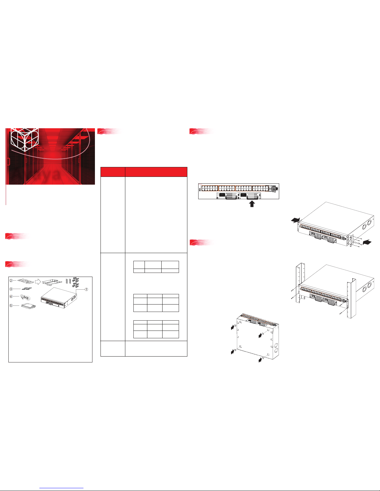
Unpack the equipment and verify
package content
Confirm that you have the following tools and cables:
• Phillips #2 screwdriver
• Console cable that matches the console connector on the
switch (DB-9 or RJ-45)
• Electrostatic discharge (ESD) cable
Virtual Services Platform 4000
4450GTX-HT-PWR+
Quick Install Guide
Avaya
1. Avaya Virtual Services Platform (VSP) 4000 4450GTX-HT-PWR+
switch with one power supply installed.
2. Rack-mounting hardware that includes:
a. Rack-mount brackets
b. Screws to attach brackets to the switch
c. Screws to attach the switch to the equipment rack
3. Rubber footpads.
4. AC power cord with an IEC 60320 C16 connector.
(Note: A power cord is not included for the A variant of
the switch.)
5. Documentation that includes:
a. Locating the latest software and product release notes
(NN46251-106)
b. Regulatory Guide (NN46251-105)
c. Quick Install Guide (this document)
d. China RoHS paper
1
Before you start
This document provides information and instructions to install
and commission a factory-supplied Avaya Virtual Services
Platform 4000 4450GTX-HT-PWR+ switch. This hardware
model is temperature hardened and designed to withstand
industrial-grade high temperatures. You can download all
documents referenced in this guide at http://support.avaya.com.
The VSP 4000 4450GTX-HT-PWR+ switch supports two
field-replaceable AC PSUs. One PSU is supplied with the
chassis. Optionally order an additional PSU for redundancy and
load sharing.
VSP 4000 4450GTX-HT-PWR+ AC power and
temperature specifications
Use this procedure to optionally install a redundant power supply.
Note: The switch ships with a filler panel in the second power
supply position. This filler panel must stay in place if you do not
intend to install a second power supply. Each power supply bay
must always be populated with either a cover or a power supply for
proper air-flow management.
Note: Observe ESD precautions when unpacking.
3
Verify power supply unit (PSU)
specifications
Specifications Description
PSU Specifications Primary PSU (without power cord):
1000-watt AC PoE+ high-temperature
field-replaceable power supply
(replacement order code: EC4005A03-E6)
Redundant PSU (without power cord):
1000-watt AC PoE+ high-temperature
field-replaceable power supply
(replacement order code: EC4005A03-E6)
Primary PSU
(with North American power cord):
1000-watt AC PoE+ high-temperature
field-replaceable power supply
(replacement order code: EC4005E03-E6)
Redundant PSU
(with North American power cord):
1000-watt AC PoE+ high-temperature
field-replaceable power supply
(replacement order code: EC4005E03-E6)
Note: The 1000-watt AC power supply uses the IEC
60320 C16 AC power cord connector.
The maximum PoE+ wattage is
as follows:
Power over Ethernet
(PoE)
and
Power over Ethernet
Plus (PoE+)
specifications
The VSP 4450GTX-HT-PWR+ has 48 ports that are
capable of POE and POE+ power support. The
following tables list the PoE and PoE+ support based
on the operating temperature.
1 PSU:
4
(Optional) Install redundant PSU
1.
If a blanking plate covers the required power supply slot,
remove the blanking plate before attempting to insert the
power supply.
2. Insert the power supply into a front power supply slot as
illustrated.
3. Verify that each power supply is fully seated in the slot.
Secure the power supply with the two thumb screws.
Note: The switch chassis can prevent an incorrect installation
of a power supply. If you insert a power supply upside down, it
will not fully insert and the thumb screws will not engage.
4. After you install a power supply, connect AC power.
a. Table or shelf mounting
Caution: To protect the VSP 4000 switch against ESD damage, do
the following before you connect the data cables to
the device:
• Use antistatic wrist straps. Ensure that the strap has good skin
contact. Do not remove the wrist or ankle strap until the
installation is complete.
• Ensure that you properly ground work surfaces and
equipment racks.
• Avoid contact between equipment and clothing.
• Avoid touching the connector pins.
0ºC to 50ºC 50ºC to 70ºC
1 PSU
2 PSUs
860 watts
1660 watts
400 watts
832 watts
0ºC to 50ºC 50ºC to 70ºC
PoE
support on
PoE+
support on
48 ports
26 ports
23 ports
13 ports
2 PSUs:
0ºC to 50ºC 50ºC to 70ºC
PoE
support on
PoE+
support on
48 ports
48 ports
48 ports
26 ports
The supported operating temperature is 0ºC to 70ºC.
Caution: To prevent equipment damage, ensure
that the operating temperature range is strictly
adhered to.
Operating
temperature
specifications
1
2
3
4
5
6
7
8
11
12
9
10
13
14
15
161718
19
20
23
24
21
22
25
26
27
28
29
30
31
32
35
36
33
34
37
38
39
40
41
42
43
44
47
48
45
46
VSP 4450GTX-HT--PWR+
PWR
Status
RPS
Up
Down
Base
USB
Speed
Speed
b. Rack mounting
2.
Slide the switch into the rack as illustrated. Insert and tighten the
rack-mount screws.
Prepare the rack:
1. Allocate 2U of vertical space for each switch in an EIA or
IEC-standard 19-inch (48.2-centimeter) equipment rack.
Ensure that the equipment rack is stable and securely attached
to a permanent structure.
2. Ground the rack to the same grounding electrode used by the
power service in the area. The ground path must be permanent
and must not exceed 1 ohm of resistance from the rack to the
grounding electrode. Avaya recommends using a filter or
surge suppressor.
Mount the switch:
1. Attach an L-bracket to each side of the switch using the #2
Phillips screwdriver as illustrated.
For more details on installing the VSP 4000, see
Installing the Avaya Virtual Services Platform 4000
VSP4450GTX-HT-PWR+ (NN46251-304).
PWR
Status
RPS
Up
Down
Base
USB
Speed
Speed
1
2
3
4
5
6
7
8
11
12
9
10
13
14
15
16
17
18
19
20
23
24
21
22
25
26
27
28
29
30
31
32
35
36
33
34
37
38
39
40
41
42
43
44
47
48
45
46
4850GTS-HT-PWR+
PWR
Status
RPS
Up
Down
Base
USB
Speed
Speed
1
2
3
4
5
6
7
8
11
12
9
10
13
14
15
16
17
18
19
20
23
24
21
22
25
26
27
28
29
30
31
32
35
36
33
34
37
38
39
40
41
42
43
44
47
48
45
46
4850GTS-HT-PWR+
1
2
3
4
5
6
7
8
11
12
9
10
13
14
15
16
17
18
19
20
23
24
21
22
25
26
27
28
29
30
31
32
35
36
33
34
37
38
39
40
41
42
43
44
47
48
45
46
4850GTS-HT-PWR+
PWR
Status
RPS
Up
Down
Base
USB
Speed
Speed
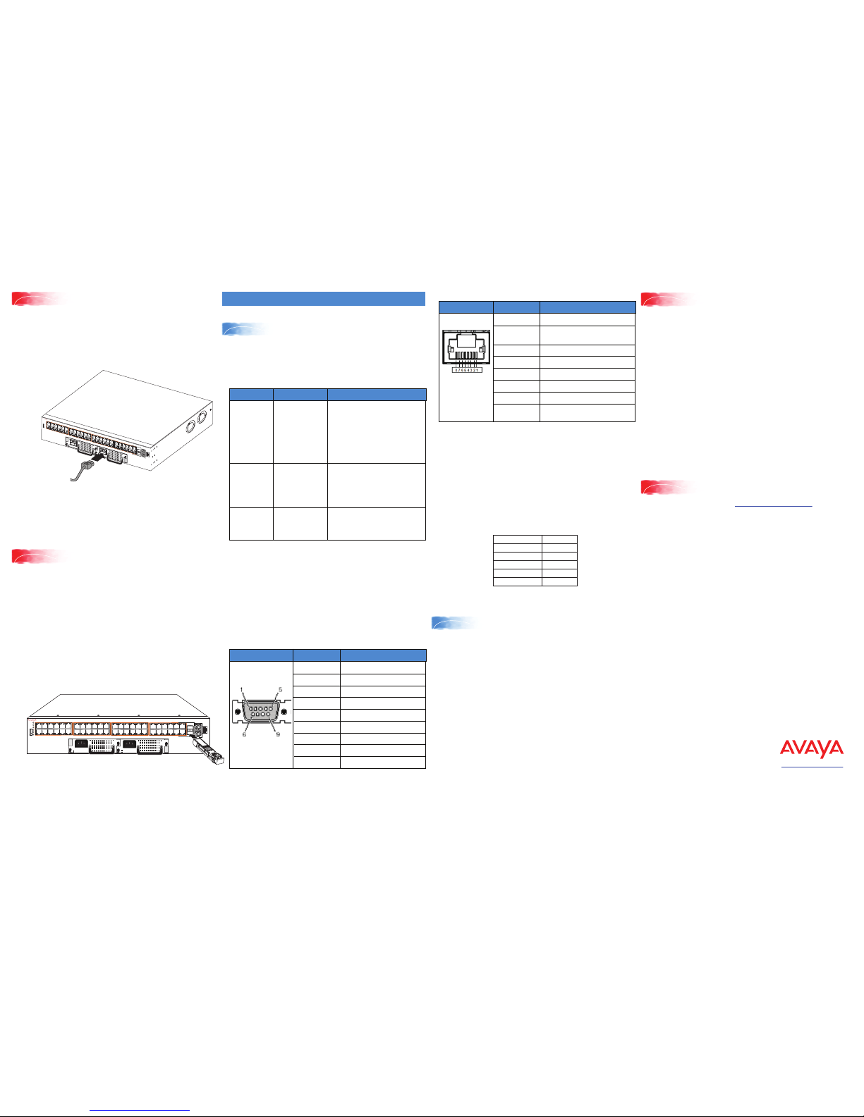
2
1
Connect the console cable to the VSP 4000
Commissioning the VSP 4000
Property Value
Baud Rate 9600 bps
Data Bits 8
Stop Bits 1
Parity None
Flow Control None
http://support.avaya.com
1-800-242-2121 (U.S.A.)
1-866 GO-AVAYA
1-866-462-8292 (US Sales)
© 2016 Avaya Inc.
Poster part number: 700510122 Rev.04
NN46251-306, 04.01
1.
Connect the AC power cord to the front of the switch, and then
plug the other end of the cord into an AC power outlet.
Note: You will need two power cords if you have installed a
redundant PSU.
Warning: You must use a power cord set approved for the 4000
Series switch and the power receptacle type in your country.
2.
Check the front-panel LEDs as the device powers on to be sure
the PWR LED is lit. If not, check whether the power cord is
plugged in correctly. The switch will power on immediately
when it is connected to a suitable AC power source.
6
Power up
Note: Before installing, ensure that the VSP 4000 switch is
operating normally. Verify that the SFP or SFP+ transceivers and
network cabling support your network configuration.
1. Select transceivers (SFP/SFP+) that are rated for
temperatures of 85°C.
2. Remove the transceiver from the protective packaging.
3. Verify that the transceiver is the correct model for the
network configuration.
4. Grasp the transceiver between your thumb and forefinger.
5. Insert the transceiver into the proper SFP/SFP+ slot on the
switch as illustrated. Apply a light pressure to the transceiver
until it clicks and locks into position in the slot.
7
Install SFP and SFP+ transceivers
Console port cabling specifications
Ensure the use of Category 5E or higher specification cabling
for 1 Gbps/1000 Mbps operation. RJ-45 console port cables
and their Product Engineering Codes (PEC) are as follows:
Connector Pin Number Signal
1
2
3
4
5
6
7
8
9
Carrier detect (not used)
Transmit data (TXD)
Receive data (RXD)
Data terminal ready (not used)
Signal ground (GND)
Not used
Request to send (not used)
Not used
Ring indicator (not used)
RJ-45 console port pin assignments
Connector Pin Number Signal
1
2
Ready to send (RTS) — optional
Data terminal ready (DTR) —
optional, can swap or link with pin 8
3
4
5
6
7
Transmit data (TXD) — mandatory
Carrier detect (DCD) — optional
Ground (GND) — mandatory
Receive data (RXD) — mandatory
Data set ready (DSR) — optional
8 Clear to send (CTS) — optional,
can swap or link with pin 1.
Note: In the following procedure you create a VLAN with
ID 20 and name Avaya.
1. Create a VLAN:
VSP-4450GTX-HT-PWR+(config)#vlan create 20 name
Avaya type port-mstprstp 0
2. Add VLAN members:
VSP-4450GTX-HT-PWR+(config)#vlan members add 20 1/4
3. Configure a management IP interface for the VLAN
(for example, 47.17.123.85):
VSP-4450GTX-HT-PWR+(config)#interface vlan 20
VSP-4450GTX-HT-PWR+(config)#ip address
47.17.123.85 255.255.255.0
1. Connect the console cable from the terminal to the console
port of the switch to allow initial configuration. Any terminal
or PC with the appropriate terminal emulator can be used as
the management station.
2. Set the terminal protocol on the terminal or terminal
emulation program to VT100 or VT100/ANSI.
3. Connect to the switch using the terminal or terminal
emulation application.
Terminal emulation settings
PEC Name Short Description
Avaya RJ-45/DB-9
CONSOLE CABLE
The VSP 4000 has an RJ-45 female
connector, so a serial cable with
RJ-45 connectors, or a serial cable
with a DB-9 female connector on
one end and an RJ-45 on the other
is required.
The maximum length for the console
port cable is 25 feet (8.3 meters).
Converts DB-9 male to RJ-45 serial
port. The adaptor can be used for
PC or device with DB-9 male
console port. Also, can be used with
Category 5 RJ-45 straight cable to
provide console connection.
Converts DB-9 female to RJ-45
serial port. This adaptor can be used
to convert DB-9 of AL2011013-E6
console cable to RJ-45.
AL2011022-E6
AVAYA RED DB-9
FEMALE TO
RJ-45 ADAPTOR
AL2011020-E6
AVAYA BL UE
DB-9 MALE TO
RJ-45 ADAPTOR
AL2011021-E6
On your VSP 4000 switch, the console port is the RJ-45 port
outlined with a blue border and marked 10101, on the front of
your switch (note the side orientation). Use an RJ-45 to DB-9
cable to connect the switch console port to your management
terminal. Use adaptors to provide different connection options.
The maximum length of a console cable is 25 feet (8.3
meters). The following tables describe the RJ-45 and DB-9
console port pin-out information. You can use the pin-out
information to verify or create a console cable for use with your
maintenance terminal.
DB-9 console port pin assignments
Configure an in-band VLAN and a
management IP interface for the VLAN
1
2
3
4
5
6
7
8
11
12
9
10
13
14
15
16
17
18
19
20
23
24
21
22
25
26
27
28
29
30
31
32
35
36
33
34
37
38
39
40
41
42
43
44
47
48
45
46
VSP 4450GTX-HT--PWR+
PWR
Status
RPS
Up
Down
Base
USB
Speed
Speed
For more information, go to http://support.avaya.com and
download the following VSP 4000 guides:
•
Regulatory Information (NN46251-105)
•
Locating the latest Software and product Release Notes
(NN46251-106)
•
Documentation Reference, NN47227-100
•
Installation (NN46251-307)
•
Quick Start Configuration, NN47227-102
•
Release Notes (NN47227-401)
•
Administration (NN47227-600)
Caution: Before you unplug the AC power cord, always perform
the following shutdown procedure. This procedure flushes any
pending data to ensure data integrity.
1. Enter the Privileged EXEC command mode:
enable
2. Shut down the VSP 4000:
sys shutdown
When prompted, enter y to confirm the shutdown.
3. Before you unplug the power cord, wait until you see the
following message:
System Halted, OK to turn off power.
For more information on this and other administration
procedures, see Administering VSP Operating System
Software (NN47227-600).
Shutting down the VSP 4000
Recommended reading
1
2
3
4
5
6
7
8
11
12
9
10
13
14
15
16
17
18
19
20
23
24
21
22
25
26
27
28
29
30
31
32
35
36
33
34
37
38
39
40
41
42
43
44
47
48
45
46
4850GTS-HT-PWR+
 Loading...