

Page 1

Configuration — Layer 2 Ethernet
Avaya Secure Router 2330/4134
Release 10.3.5
NN47263-501
Issue 04.03
July 2013
Page 2

©
2013 Avaya Inc.
All Rights Reserved.
Notice
While reasonable efforts have been made to ensure that the
information in this document is complete and accurate at the time of
printing, Avaya assumes no liability for any errors. Avaya reserves the
right to make changes and corrections to the information in this
document without the obligation to notify any person or organization of
such changes.
Documentation disclaimer
“Documentation” means information published by Avaya in varying
mediums which may include product information, operating instructions
and performance specifications that Avaya generally makes available
to users of its products. Documentation does not include marketing
materials. Avaya shall not be responsible for any modifications,
additions, or deletions to the original published version of
documentation unless such modifications, additions, or deletions were
performed by Avaya. End User agrees to indemnify and hold harmless
Avaya, Avaya's agents, servants and employees against all claims,
lawsuits, demands and judgments arising out of, or in connection with,
subsequent modifications, additions or deletions to this documentation,
to the extent made by End User.
Link disclaimer
Avaya is not responsible for the contents or reliability of any linked
websites referenced within this site or documentation provided by
Avaya. Avaya is not responsible for the accuracy of any information,
statement or content provided on these sites and does not necessarily
endorse the products, services, or information described or offered
within them. Avaya does not guarantee that these links will work all the
time and has no control over the availability of the linked pages.
Warranty
Avaya provides a limited warranty on its hardware and Software
(“Product(s)”). Refer to your sales agreement to establish the terms of
the limited warranty. In addition, Avaya’s standard warranty language,
as well as information regarding support for this Product while under
warranty is available to Avaya customers and other parties through the
Avaya Support website:
you acquired the Product(s) from an authorized Avaya reseller outside
of the United States and Canada, the warranty is provided to you by
said Avaya reseller and not by Avaya. “Software” means computer
programs in object code, provided by Avaya or an Avaya Channel
Partner, whether as stand-alone products or pre-installed on hardware
products, and any upgrades, updates, bug fixes, or modified versions.
Licenses
THE SOFTWARE LICENSE TERMS AVAILABLE ON THE AVAYA
WEBSITE,
APPLICABLE TO ANYONE WHO DOWNLOADS, USES AND/OR
INSTALLS AVAYA SOFTWARE, PURCHASED FROM AVAYA INC.,
ANY AVAYA AFFILIATE, OR AN AUTHORIZED AVAYA RESELLER
(AS APPLICABLE) UNDER A COMMERCIAL AGREEMENT WITH
AVAYA OR AN AUTHORIZED AVAYA RESELLER. UNLESS
OTHERWISE AGREED TO BY AVAYA IN WRITING, AVAYA DOES
NOT EXTEND THIS LICENSE IF THE SOFTWARE WAS OBTAINED
FROM ANYONE OTHER THAN AVAYA, AN AVAYA AFFILIATE OR
AN AVAYA AUTHORIZED RESELLER; AVAYA RESERVES THE
RIGHT TO TAKE LEGAL ACTION AGAINST YOU AND ANYONE
ELSE USING OR SELLING THE SOFTWARE WITHOUT A LICENSE.
BY INSTALLING, DOWNLOADING OR USING THE SOFTWARE, OR
AUTHORIZING OTHERS TO DO SO, YOU, ON BEHALF OF
YOURSELF AND THE ENTITY FOR WHOM YOU ARE INSTALLING,
DOWNLOADING OR USING THE SOFTWARE (HEREINAFTER
REFERRED TO INTERCHANGEABLY AS “YOU” AND “END USER”),
AGREE TO THESE TERMS AND CONDITIONS AND CREATE A
BINDING CONTRACT BETWEEN YOU AND AVAYA INC. OR THE
APPLICABLE AVAYA AFFILIATE (“AVAYA”).
HTTP://SUPPORT.AVAYA.COM/LICENSEINFO ARE
http://support.avaya.com. Please note that if
Avaya grants you a license within the scope of the license types
described below, with the exception of Heritage Nortel Software, for
which the scope of the license is detailed below. Where the order
documentation does not expressly identify a license type, the
applicable license will be a Designated System License. The applicable
number of licenses and units of capacity for which the license is granted
will be one (1), unless a different number of licenses or units of capacity
is specified in the documentation or other materials available to you.
“Designated Processor” means a single stand-alone computing device.
“Server” means a Designated Processor that hosts a software
application to be accessed by multiple users.
Copyright
Except where expressly stated otherwise, no use should be made of
materials on this site, the Documentation, Software, or hardware
provided by Avaya. All content on this site, the documentation and the
Product provided by Avaya including the selection, arrangement and
design of the content is owned either by Avaya or its licensors and is
protected by copyright and other intellectual property laws including the
sui generis rights relating to the protection of databases. You may not
modify, copy, reproduce, republish, upload, post, transmit or distribute
in any way any content, in whole or in part, including any code and
software unless expressly authorized by Avaya. Unauthorized
reproduction, transmission, dissemination, storage, and or use without
the express written consent of Avaya can be a criminal, as well as a
civil offense under the applicable law.
Third Party Components
“Third Party Components” mean certain software programs or portions
thereof included in the Software that may contain software (including
open source software) distributed under third party agreements (“Third
Party Components”), which contain terms regarding the rights to use
certain portions of the Software (“Third Party Terms”). Information
regarding distributed Linux OS source code (for those Products that
have distributed Linux OS source code) and identifying the copyright
holders of the Third Party Components and the Third Party Terms that
apply is available in the Documentation or on Avaya’s website at:
support.avaya.com/Copyright. You agree to the Third Party Terms for
any such Third Party Components.
Note to Service Provider
The Product may use Third Party Components that have Third Party
Terms that do not allow hosting and may need to be independently
licensed for such purpose.
Preventing Toll Fraud
“Toll Fraud” is the unauthorized use of your telecommunications
system by an unauthorized party (for example, a person who is not a
corporate employee, agent, subcontractor, or is not working on your
company's behalf). Be aware that there can be a risk of Toll Fraud
associated with your system and that, if Toll Fraud occurs, it can result
in substantial additional charges for your telecommunications services.
Avaya Toll Fraud intervention
If you suspect that you are being victimized by Toll Fraud and you need
technical assistance or support, call Technical Service Center Toll
Fraud Intervention Hotline at +1-800-643-2353 for the United States
and Canada. For additional support telephone numbers, see the Avaya
Support website:
vulnerabilities with Avaya products should be reported to Avaya by
sending mail to: [email protected].
Trademarks
The trademarks, logos and service marks (“Marks”) displayed in this
site, the Documentation and Product(s) provided by Avaya are the
registered or unregistered Marks of Avaya, its affiliates, or other third
parties. Users are not permitted to use such Marks without prior written
consent from Avaya or such third party which may own the Mark.
Nothing contained in this site, the Documentation and Product(s)
should be construed as granting, by implication, estoppel, or otherwise,
http://support.avaya.com. Suspected security
http://
2 Configuration — Layer 2 Ethernet July 2013
Comments? [email protected]
Page 3

any license or right in and to the Marks without the express written
permission of Avaya or the applicable third party.
Avaya is a registered trademark of Avaya Inc.
All non-Avaya trademarks are the property of their respective owners.
Linux® is the registered trademark of Linus Torvalds in the U.S. and
other countries.
Downloading Documentation
For the most current versions of Documentation, see the Avaya
Support website: http://support.avaya.com.
Contact Avaya Support
See the Avaya Support website: http://support.avaya.com for product
notices and articles, or to report a problem with your Avaya product.
For a list of support telephone numbers and contact addresses, go to
the Avaya Support website: http://support.avaya.com, scroll to the
bottom of the page, and select Contact Avaya Support.
Configuration — Layer 2 Ethernet July 2013 3
Page 4

Page 5

Contents
Chapter 1: Introduction......................................................................................................
Introduction...............................................................................................................................................
Related Resources....................................................................................................................................
Documentation.................................................................................................................................
Training............................................................................................................................................
Avaya Mentor videos........................................................................................................................
Support.............................................................................................................................................
Chapter 2: New in this release...........................................................................................
Features....................................................................................................................................................
Common and internal spanning tree information.............................................................................
Other changes...........................................................................................................................................
Chapter 3: Secure Router 2330/4134 Ethernet interface fundamentals.........................
Ethernet interface fundamentals...............................................................................................................
FE and FE/PoE Medium Modules....................................................................................................
GbE Medium Module........................................................................................................................
GbE Large Module...........................................................................................................................
Chassis Ethernet ports.....................................................................................................................
Chapter 4: Ethernet Connectivity Fault Management......................................................
Maintenance Domain................................................................................................................................
Maintenance End Point....................................................................................................................
Maintenance Intermediate Point.......................................................................................................
Connectivity Fault Management messages.....................................................................................
Connectivity Fault Management modes....................................................................................................
Connectivity Fault Management errors and statistics...............................................................................
Chapter 5: Layer 2 fundamentals......................................................................................
Layer 2 switching and bridging.................................................................................................................
MAC bridging............................................................................................................................................
VLANs.......................................................................................................................................................
Independent VLAN learning.............................................................................................................
Static multicast MAC filtering............................................................................................................
VLAN classification...........................................................................................................................
VLAN stacking..................................................................................................................................
Multiple IP Helper Addresses on a VLAN.........................................................................................
Spanning Tree Protocol............................................................................................................................
Multiple Spanning Tree Protocol......................................................................................................
MSTP regions...................................................................................................................................
Common Spanning Tree..................................................................................................................
MSTP instance.................................................................................................................................
Rapid transitions...............................................................................................................................
IGMP Snooping.........................................................................................................................................
IGMP proxy......................................................................................................................................
IGMP querier....................................................................................................................................
Query interval...................................................................................................................................
Last member query interval..............................................................................................................
11
11
11
11
11
11
12
13
13
13
13
15
15
15
17
18
18
21
21
22
26
27
28
28
29
29
29
30
31
32
32
33
33
34
34
35
36
37
38
39
40
40
40
41
Configuration — Layer 2 Ethernet July 2013 5
Page 6

Maximum response time..................................................................................................................
Fast-leave processing......................................................................................................................
Multicast router ports........................................................................................................................
GVRP........................................................................................................................................................
Link aggregation........................................................................................................................................
LACP................................................................................................................................................
Port mirroring............................................................................................................................................
Selectable range of ports..........................................................................................................................
Chapter 6: Power over Ethernet configuration................................................................
Configuring the PoE port mode.................................................................................................................
Configuring PoE port power......................................................................................................................
Configuring PoE port priority commands..................................................................................................
Configuring PoE device detection.............................................................................................................
Configuring PoE port power limits.............................................................................................................
Viewing PoE information...........................................................................................................................
Chapter 7: Ethernet Connectivity Fault Management configuration..............................
Accessing the CFM tools..........................................................................................................................
Configuring the number of path trace cache entries.................................................................................
Configuring the CFM frame ethertype.......................................................................................................
Enabling CFM event messages................................................................................................................
Creating a Maintenance Domain..............................................................................................................
Configuring a Maintenance Association....................................................................................................
Configuring a Maintenance End Point......................................................................................................
Deleting a Maintenance End Point...................................................................................................
Configuring a remote Maintenance End Point..........................................................................................
Deleting a remote Maintenance End Point...............................................................................................
Configuring a Maintenance Intermediate Point.........................................................................................
Deleting a Maintenance Intermediate Point.....................................................................................
Configuring Continuity Check Messages..................................................................................................
Removing an auto-detected remote Maintenance End Point...................................................................
Issuing CFM loopback tests......................................................................................................................
Verifying the path to a remote MEP.................................................................................................
Verifying the path to a remote MIP...................................................................................................
Issuing CFM linktrace tests.......................................................................................................................
Tracing the path to a remote MEP...................................................................................................
Tracing the path to a remote MIP.....................................................................................................
Example of configuring Ethernet Connectivity Fault Management...........................................................
Displaying Ethernet CFM information.......................................................................................................
Displaying information related to Maintenance Domains.................................................................
Displaying information related to Maintenance Associations...........................................................
Displaying information related to MEPs and MIPs...........................................................................
Displaying information related to continuity checks..........................................................................
Displaying information related to CFM errors...................................................................................
Displaying information related to CFM stats.....................................................................................
Displaying information related to path trace cache entries...............................................................
Displaying CFM global configuration................................................................................................
Clearing Ethernet CFM information...........................................................................................................
41
41
42
42
43
43
43
44
45
45
46
47
48
48
49
51
51
51
52
53
54
55
56
57
58
59
59
60
61
62
62
63
64
65
65
66
67
71
71
72
72
73
73
74
75
75
76
6 Configuration — Layer 2 Ethernet July 2013
Page 7

Chapter 8: Secure Router 2330/4134 Ethernet interfaces configuration.......................
Configuring Maximum Transmission Unit size..........................................................................................
Configuring jumbo frames.........................................................................................................................
Adding comments to an interface.............................................................................................................
Adding comments at the beginning of a configuration file................................................................
Adding comments at the end of a configuration file.........................................................................
Adding a description to an interface.................................................................................................
Configuring the speed of an interface.......................................................................................................
Chapter 9: Layer 2 configuration.......................................................................................
Prerequisites to Layer 2 configuration......................................................................................................
Layer 2 configuration procedures.............................................................................................................
Chapter 10: Interface mode configuration........................................................................
Configuring trunking on Ethernet interfaces..............................................................................................
Enabling trunking on an Ethernet port..............................................................................................
Specifying VLANs to trunk................................................................................................................
Disabling trunking.............................................................................................................................
Verifying trunks.................................................................................................................................
Example of configuring trunking on a chassis Ethernet interface.....................................................
Configuring trunking on a WAN interface..................................................................................................
Enabling trunking on WAN interfaces...............................................................................................
Adding all VLANs to a trunk link.......................................................................................................
Removing all VLANs from a trunk link..............................................................................................
Adding a specified VLAN to a trunk link...........................................................................................
Removing a specified VLAN from a trunk link..................................................................................
Disabling trunking.............................................................................................................................
Verifying trunks.................................................................................................................................
Example of configuring trunking on a WAN interface.......................................................................
Configuring a hybrid link on an Ethernet interface....................................................................................
Associating VLANs with hybrid links................................................................................................
Disabling a hybrid link......................................................................................................................
Verifying a hybrid link.......................................................................................................................
Example of configuring a hybrid link on a chassis Ethernet interface..............................................
Configuring a hybrid link on a WAN interface...........................................................................................
Enabling a hybrid link on a WAN interface.......................................................................................
Adding all VLANs to a hybrid link.....................................................................................................
Removing all VLANs from a hybrid link............................................................................................
Adding a specified VLAN to a hybrid link.........................................................................................
Removing a specified VLAN from a link...........................................................................................
Disabling a hybrid link......................................................................................................................
Verifying a hybrid link.......................................................................................................................
Example of configuring a hybrid link on a WAN interface................................................................
Configuring an access port on an Ethernet interface................................................................................
Enabling an access link on an Ethernet port....................................................................................
Associating VLANs with access links...............................................................................................
Disabling an access port..................................................................................................................
Verifying an access port...................................................................................................................
Configuring an access port on a WAN interface.......................................................................................
77
77
78
78
79
79
80
81
83
83
83
85
85
85
86
87
88
88
88
89
90
90
90
91
91
91
92
92
93
95
95
95
96
96
97
97
98
98
98
99
99
99
100
100
100
101
101
Configuration — Layer 2 Ethernet July 2013 7
Page 8

Enabling an access link on a WAN interface....................................................................................
Changing the VLAN on an access port............................................................................................
Disabling an access port..................................................................................................................
Verifying an access port...................................................................................................................
Example of configuring an access port on a WAN interface............................................................
Chapter 11: Link aggregation configuration....................................................................
Configuring LACP.....................................................................................................................................
Configuring static mode....................................................................................................................
Configuring passive mode................................................................................................................
Configuring active mode...................................................................................................................
Changing the channel group.....................................................................................................................
Example of changing the channel group number to reconfigure an interface..................................
Removing LACP configuration..................................................................................................................
Configuring the LACP timeout..................................................................................................................
Configuring LACP system priority.............................................................................................................
Restoring the default LACP system priority......................................................................................
Configuring a LAG interface......................................................................................................................
Prerequisites....................................................................................................................................
Example of configuring a LAG interface...........................................................................................
Verifying the successful configuration of a LAG.......................................................................................
Viewing channel-group information..................................................................................................
Viewing aggregator member information.........................................................................................
Viewing LACP dynamic information.................................................................................................
Viewing LAG interface information...................................................................................................
Example of configuring LACP...................................................................................................................
Configuration on SWITCH_1............................................................................................................
Configuration on SWITCH_2............................................................................................................
Chapter 12: VLAN configuration........................................................................................
Creating a VLAN.......................................................................................................................................
Removing a VLAN.....................................................................................................................................
Verifying VLANs........................................................................................................................................
Shutting down a VLAN interface...............................................................................................................
Configuring multiple IP Helper addresses on a VLAN..............................................................................
Example of creating VLANs and binding each VLAN to an interface.......................................................
Example of creating VLANs.............................................................................................................
Example of binding a bundle access interface to a VLAN................................................................
Example of binding a LAG trunk port to VLANs...............................................................................
Example of binding an Ethernet hybrid port to VLANs.....................................................................
Chapter 13: VLAN classification configuration................................................................
Creating VLAN classification rules............................................................................................................
Configuring an IPv4 subnet-based VLAN classification rule............................................................
Configuring a protocol-based VLAN classification rule....................................................................
Deleting VLAN classification rules............................................................................................................
Verifying VLAN classification rules............................................................................................................
Creating VLAN classification rules on an interface...................................................................................
Creating protocol VLAN classification rules.....................................................................................
Creating IPv4 VLAN classification rules...........................................................................................
101
102
103
103
103
105
105
105
106
106
107
107
108
108
109
109
110
110
110
111
111
111
111
112
112
112
113
115
115
115
116
116
116
117
117
118
119
119
121
121
121
122
123
123
123
124
124
8 Configuration — Layer 2 Ethernet July 2013
Page 9

Deleting VLAN classification rules from an interface................................................................................
Deleting protocol rules from an interface..........................................................................................
Deleting IPv4 rules from an interface...............................................................................................
Example of configuring VLAN classification rules.....................................................................................
Chapter 14: VLAN stacking configuration........................................................................
Enabling VLAN stacking............................................................................................................................
Disabling VLAN stacking...........................................................................................................................
Verifying VLAN stacking configuration......................................................................................................
Example of configuring VLAN stacking.....................................................................................................
Configuration of the Secure Router 2330/4134 on interface A.........................................................
Configuration of the Secure Router 2330/4134 on interface B.........................................................
Configuration of the Secure Router 2330/4134 on interface C........................................................
Chapter 15: Port mirroring configuration.........................................................................
Enabling port mirroring..............................................................................................................................
Disabling port mirroring.............................................................................................................................
Verifying port mirroring configuration........................................................................................................
Example of configuring port mirroring.......................................................................................................
Chapter 16: MAC entry configuration...............................................................................
Adding static MAC address entries to the MAC address table.................................................................
Deleting a static MAC address entry.........................................................................................................
Verifying static MAC address entries........................................................................................................
Example of configuring static MAC address entries.................................................................................
Configuring MAC address aging time.......................................................................................................
Restoring the default MAC address aging time........................................................................................
Verifying the MAC address aging time......................................................................................................
Example of configuring MAC address aging time.....................................................................................
Chapter 17: Multiple Spanning Tree Protocol configuration..........................................
Configuring the region name and revision number...................................................................................
Resetting the revision number..........................................................................................................
Configuring Common Spanning Tree.......................................................................................................
Configuring bridge priority................................................................................................................
Configuring hop count......................................................................................................................
Configuring link path cost and priority..............................................................................................
Configuring PortFast........................................................................................................................
Configuring PortFast BPDU Guard..................................................................................................
Configuring PortFast BPDU Filter....................................................................................................
Configuring MSTP timers.................................................................................................................
Configuring forward delay................................................................................................................
Configuring maximum age time........................................................................................................
Configuring link types.......................................................................................................................
Configuring an MSTP instance.................................................................................................................
Creating an MSTP instance.............................................................................................................
Associating a VLAN with an instance...............................................................................................
Configuring priority for an instance...................................................................................................
Configuring link path cost and priority for an instance......................................................................
Verifying MSTP operation.........................................................................................................................
Viewing information for MSTP Common Spanning Tree..................................................................
124
124
125
125
127
127
127
128
128
130
130
131
133
133
134
134
134
135
135
135
136
136
136
137
137
138
139
139
140
140
140
141
143
146
148
149
150
152
154
155
157
157
158
159
161
164
164
Configuration — Layer 2 Ethernet July 2013 9
Page 10

Viewing common and internal spanning tree information.................................................................
Viewing information for MSTP instances..........................................................................................
Viewing bridge information for an instance......................................................................................
Viewing interface information...........................................................................................................
Viewing VLAN information for all instances......................................................................................
Viewing VLAN information for a specified instance..........................................................................
Chapter 18: GVRP configuration.......................................................................................
Enabling GVRP globally............................................................................................................................
Disabling GVRP globally...........................................................................................................................
Enabling GVRP on ports and configuring port registration state..............................................................
Disabling GVRP on an interface...............................................................................................................
Configuring GVRP for dynamic VLAN creation.........................................................................................
Disabling dynamic VLAN creation.............................................................................................................
Configuring GVRP timers..........................................................................................................................
Resetting GVRP timers.............................................................................................................................
Verifying GVRP configuration...................................................................................................................
Clearing GVRP command options............................................................................................................
Example of configuring GVRP..................................................................................................................
Example of configuring SWITCH_1..................................................................................................
164
165
165
165
166
166
167
167
167
168
169
169
170
171
172
172
173
174
174
10 Configuration — Layer 2 Ethernet July 2013
Page 11

Chapter 1: Introduction
Introduction
This document provides information you need to configure Ethernet interfaces and Layer 2
features.
Related Resources
Documentation
See the Avaya Secure Router 2330/4134 Documentation Roadmap, NN47263-103, for a list
of the documentation for this product.
Training
Ongoing product training is available. For more information or to register, you can access the
Web site at http://avaya-learning.com.
Avaya Mentor videos
Avaya Mentor is an Avaya-run channel on YouTube that includes technical content on how to
install, configure, and troubleshoot Avaya products.
Go to http://www.youtube.com/AvayaMentor and perform one of the following actions:
• Enter a key word or key words in the Search Channel to search for a specific product
or topic.
• Scroll down Playlists, and click the name of a topic to see the available list of videos
posted on the site.
Configuration — Layer 2 Ethernet July 2013 11
Page 12

Introduction
Support
Visit the Avaya Support website at
documentation, product notices, and knowledge articles. You can also search for release
notes, downloads, and resolutions to issues. Use the online service request system to create
a service request. Chat with live agents to get answers to questions, or request an agent to
connect you to a support team if an issue requires additional expertise.
http://support.avaya.com for the most up-to-date
12 Configuration — Layer 2 Ethernet July 2013
Comments? [email protected]
Page 13

Chapter 2: New in this release
The following sections detail what is new in Avaya Secure Router 2330/4134 Configuration — Layer 2
Ethernet (NN47263-501) for Release 10.3.5.
Features
The following new feature content has been added to Avaya Secure Router 2330/4134
Configuration — Layer 2 Ethernet (NN47263-501) for Release 10.3.5.
Common and internal spanning tree information
The common and internal spanning tree (CIST) is the default spanning tree instance of Multiple
Spanning Tree Protocol (MSTP). Avaya Secure Router 2330/4134 Release 10.3.5 introduces
a command that allows you to view CIST information for a VLAN or a port. For more information,
see Viewing common and internal spanning tree information on page 164.
Other changes
The following section details other changes made to Avaya Secure Router 2330/4134
Configuration — Layer 2 Ethernet, (NN47263-501) for Release 10.3.5.
IGMP Snooping configuration
The chapter IGMP Snooping configuration has been removed. For information on how to
configure IGMP snooping, see Avaya Secure Router 2330/4134 Configuration — IPv4
Multicast Routing, (NN47263-504).
Configuration — Layer 2 Ethernet July 2013 13
Page 14

Page 15

Chapter 3: Secure Router 2330/4134
Ethernet interface fundamentals
Ethernet interface fundamentals
Avaya Secure Router 2330/4134 supports the following Ethernet interface modules:
• 24-port FE Medium Module
• 24-port FE/PoE Medium Module
• 10-port GbE Medium Module
• 44-port GbE Large Module
For detailed information about the interface modules that the Secure Router 2330/4134
supports, see Avaya Secure Router 2330/4134 Installation — Hardware Components
(NN47263-301).
FE and FE/PoE Medium Modules
The 24-port Fast Ethernet (FE) and Fast Ethernet/Power over Ethernet (FE/PoE) Medium
Modules each provide 24 Ethernet ports that support 10 Mbps and 100 Mbps operation over
unshielded twisted pair (UTP) wiring. The module is non-blocking. The 24-port FE and FE/PoE
Medium Modules provide both Layer 2 switching and Layer 3 routing functionality.
The 24-port PoE Medium Module supports only Alternative (or mode) A as defined in IEEE
802.3af. Power is fed over pins 1,2 and 3,6.
Important:
You must install the Secure Router 2330/4134 PoE power supply to take advantage of the
PoE capabilities.
Power over Ethernet
You can install up to two PoE power supply modules in the Secure Router 2330/4134. Each
PoE power supply can provide 400 watts. There is a total allocation of 384 watts for each PoE
card to support all 24 ports (with maximum power limit for each port is 16 watts). This section
Configuration — Layer 2 Ethernet July 2013 15
Page 16

Secure Router 2330/4134 Ethernet interface fundamentals
describes the PoE power distribution scenarios available on the Secure Router 2330/4134, as
well as the commands you use to configure PoE.
The following table describes power distribution for PoE interface modules.
Table 1: PoE power distribution
Number of
installed PoE
interface
modules
One PoE interface
module (any slot)
One PoE power
supply module
installed
410 W allocated for
the slot
Two PoE power
supply modules
installed
410 W allocated for the
slot
Port state
All ports are shut down
(no power state) until
you configure the poe
portpower or poe
portmode command
Two PoE interface
modules (any
slots)
Each slot receives
200 W
Each slot receives 410WAll ports are shut down
(no power state) until
you configure the poe
portpower or poe
portmode command
Three PoE
interface modules
(any slots)
Slot 5 and 6 each
receive 200 W.
There is no power
for slot 7.
Slot 5 receives 410 W.
Slots 6 and 7 receive
200 W each.
All ports are shut down
(no power state) until
you configure the poe
portpower or poe
portmode command
The number of powered devices that the Secure Router 2330/4134 supports is based on
available power, the number of cards present in the chassis, and the actual power consumption
of the powered devices connected to the PoE module.
The power available with one PoE power supply module installed is 400 watts. The power
available with two PoE power supply modules installed is 800 watts.
If you use a redundant PoE power supply module setup (that is, you have two PoE power
supply modules installed), the Secure Router 2330/4134 provides a failover feature that
ensures that the Secure Router 2330/4134 keeps running, even in situations where you must
remove one power supply module. The second PoE power supply module can provide enough
power for the system to operate without fail (a function of the PoE power provisioning on the
Secure Router 2330/4134).
The following table shows the number of powered devices supported based on the number of
interface modules installed in the Secure Router 2330/4134.
16 Configuration — Layer 2 Ethernet July 2013
Comments? [email protected]
Page 17

Table 2: Number of ports and PDs supported
Ethernet interface fundamentals
Number of installed PoE
interface modules
1 24 ports are supported
2 24 ports are supported on
3 24 ports are supported on
One PoE power supply
module installed
irrespective of the class of
powered devices.
each interface module with
the combination of class 1
and class 2 powered
devices.
For any other combinations
of powered devices, the
number of ports supported is
based on the actual power
consumption of the powered
devices connected to the
modules.
each interface module in slot
5 and slot 6 with the
combination of class 1 and
class 2 powered devices.
For any other combination of
powered devices, the
number of ports supported is
based on the actual power
consumption of the powered
devices connected to the
modules.
Two PoE power supply
modules installed
24 ports are supported
irrespective of the class of
powered devices.
24 ports are supported on
each interface module
irrespective of the class of
powered devices.
24 ports are supported on the
interface module in slot 5
irrespective of the powered
device class, and 24 ports
are supported on each
interface module in slot 6 and
slot 7 with the combination of
class 1 and class 2 powered
devices (that is, support for a
total of 72 ports).
For any other combination of
powered devices, the
number of ports supported is
based on the actual power
consumption of the powered
devices connected to the
interface module in slot 6 and
slot 7.
GbE Medium Module
The 10-port 10/100/1000 Ethernet Advanced Layer 2/Layer 3 Medium Module provides ten
autonegotiating 10/100/1000 Mbps copper Ethernet ports and two Small form-factor Pluggable
(SFP) Gigabit Ethernet (GbE) ports (full duplex). Up to ten ports can be in use at one time. The
module is non-blocking. The 10-port GbE Medium Module provides both Layer 2 switching and
Layer 3 routing functionality.
To use a GbE Medium Module, you must insert the SFP before you configure modular
Ethernet. The Secure Router 2330/4134 performs a system check for an installed SFP. If no
Configuration — Layer 2 Ethernet July 2013 17
Page 18

Secure Router 2330/4134 Ethernet interface fundamentals
SFP is detected, the system defaults to copper only. If an SFP is detected, the system defaults
to fiber only.
GbE Large Module
The 44-port 10/100/1000 Large Module provides 44 Ethernet ports that each support
10/100/1000 Mbps operation over unshielded twisted pair (UTP) wiring, as well as two SFP
optical ports. Up to 44 ports can be in use at one time.
The 44-port GbE Large Module provides both Layer 2 switching and Layer 3 routing
functionality. The total available bandwidth at all of the ports (44 Gbps) is four times the
available routing bandwidth.
There are three groups on the module: one group has 12 ports, and two groups have 16 ports
each. For Layer 2 switching within each group, packets can be switched at full bandwidth.
However, for Layer 2 switching between groups and for all packets that are routed (Layer 3),
all external ports must share a limited number of links on the module. There are three links
available within the group of 12 ports, and there are four links available within each group of
16 ports. There is, therefore, a 12:3 (4:1) or 16:4 (4:1) contention for the internal links.
Chassis Ethernet ports
In addition to the module Ethernet ports available for the Secure Router 2330/4134, the router
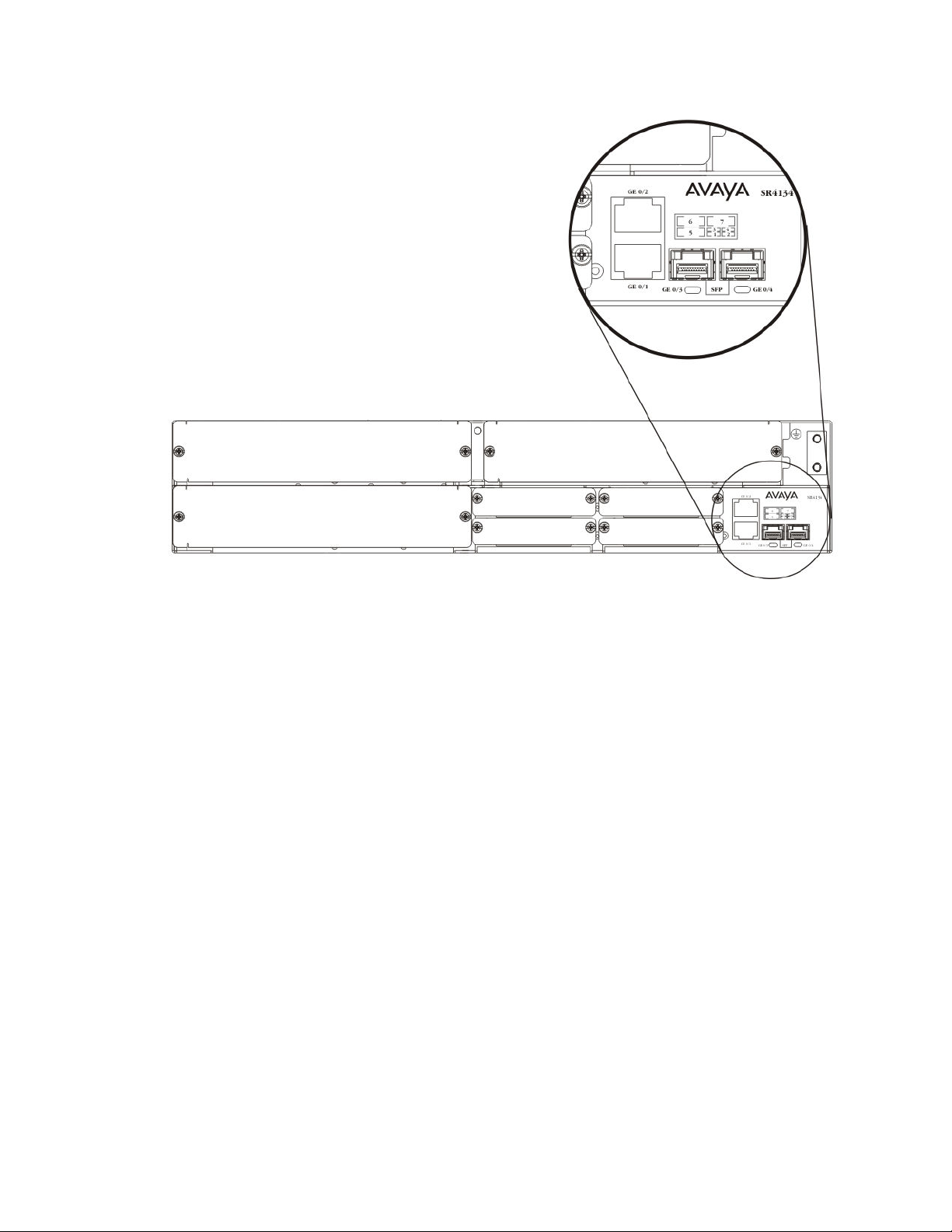
has four chassis Ethernet ports on the front panel:
• GE 0/1 and GE 0/2 ports — 10/100/1000 Base-T ports
• GE 0/3 and GE 0/4 — SFP ports
The following figure shows the location of the chassis Ethernet ports.
18 Configuration — Layer 2 Ethernet July 2013
Comments? [email protected]
Page 19
Ethernet interface fundamentals
Figure 1: Secure Router 2330/4134 chassis Ethernet ports
All Ethernet ports on the Secure Router 2330/4134 (chassis and interface module Ethernet
ports) support MDI and MDI-X.
Ethernet interfaces on the Secure Router 2330/4134 are routed interfaces, by default. To
configure them as Layer 2 interfaces, you use the switchport command.
Configuration — Layer 2 Ethernet July 2013 19
Page 20

Secure Router 2330/4134 Ethernet interface fundamentals
20 Configuration — Layer 2 Ethernet July 2013
Comments? [email protected]
Page 21

Chapter 4: Ethernet Connectivity Fault
Management
Avaya Secure Router 2330/4134 supports the 802.1ag protocol, which provides operation, administration,
maintenance (OAM) functionality for Ethernet. Specifically, IEEE 802.1ag Connectivity Fault Management
(CFM) provides OAM tools for the service layer, which allows you to monitor and troubleshoot an end-toend Ethernet service instance. Ethernet CFM enables the service provider to know if an Ethernet Virtual
Circuit (EVC) fails, and if so, provides the tools to rapidly isolate the failure.
The end-to-end service can be provider edge (PE) to PE device or customer edge (CE) to CE device. The
customer VLAN tag defines a service instance. Based on the customer VLAN, the customer receives
service as defined in their customer agreement. When you initiate CFM frames from the Secure Router
2330/4134, the frames are tagged with the C-VLAN only. CFM is not supported on an interface that uses
stacked VLANs.
Ethernet CFM is the standard for Layer 2 ping, Layer 2 traceroute, and the end-to-end connectivity check
of the Ethernet network.
Avaya supports Ethernet CFM on chassis Gigabit Ethernet (GbE) ports only.
The 802.1ag feature divides or separates a network into administrative domains called Maintenance
Domains (MD). Each MD includes the following attributes:
• Maintenance Associations (MA)
• Maintenance End Points (MEP)
• Maintenance Intermediate Points (MIP)
Maintenance Domain
A Maintenance Domain (MD) is the part of a network that is controlled by a single administrator.
For example, a customer can engage the services of a service provider, who, in turn, can
engage the services of several operators. In this scenario, there can be one MD associated
with the customer, one MD associated with the service provider, and one MD associated with
each of the operators.
The Secure Router 2330/4134 supports up to 64 MDs.
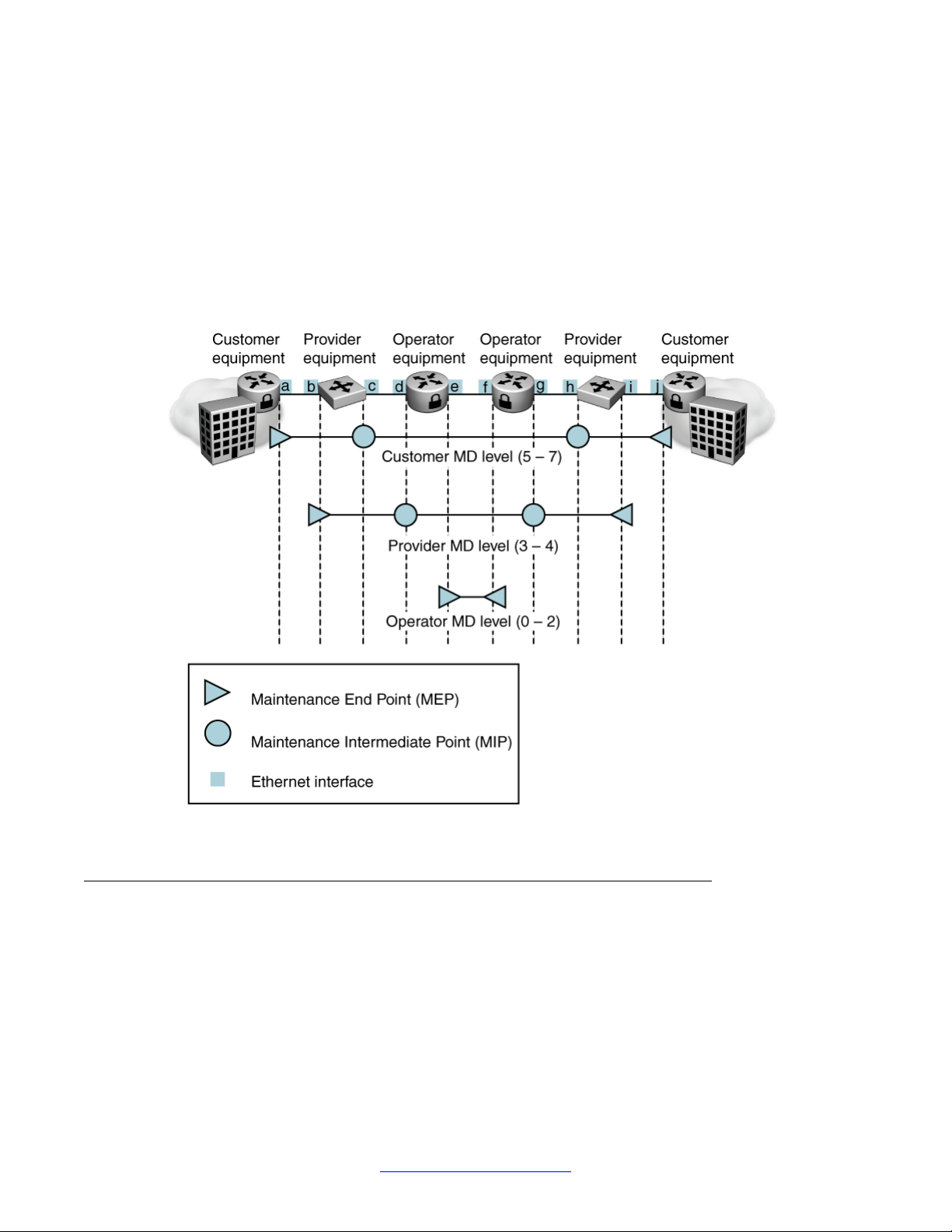
You assign one of the following eight levels to the MD:
• 0–2 (operator levels)
• 3–4 (provider levels)
• 5–7 (customer levels)
Configuration — Layer 2 Ethernet July 2013 21
Page 22
Ethernet Connectivity Fault Management
The levels separate MDs from each other and provide different areas of functionality to different
devices using the network. An MD is characterized by a level and an MD name (optional).
A single MD can contain several MAs. Each MA is defined by a set of Maintenance Points
(MP). An MP is a demarcation point on an interface that participates in CFM within an MD.
There are two types of MP:
• Maintenance End Point (MEP)
• Maintenance Intermediate Point (MIP)
The following figure shows the MD level assignments.
Figure 2: Maintenance Domain levels
Maintenance End Point
MEPs are points at the edge of the MD. They define a boundary and confine connectivity fault
management messages within this boundary.
22 Configuration — Layer 2 Ethernet July 2013
Comments? [email protected]
Page 23

Maintenance Domain
An MEP acts based on the relationship between the level assigned to the connectivity fault
management frame received and the level assigned to the MEP. The possible MEP actions
are the following:
• Drop frames that have a lower level
• Transparently forward all connectivity fault management frames that have a higher level
• For connectivity fault management frames that have the same level as the MEP, the MEP
does one of the following (based on the type of MEP):
- A Down MEP is one residing in a bridge that transmits connectivity fault management
messages towards, and receives them from, the direction of the physical medium.
For example, see
at point a in the Figure is a Down MEP. A Down MEP does the following:
• processes frames received from the wire side
• drops frames received from the relay side
- An Up MEP is one residing in a bridge that transmits connectivity fault management
messages towards, and receives them from, the direction of the bridge relay entity.
For example, see
at point b in the Figure is an Up MEP. An Up MEP does the following:
Figure 2: Maintenance Domain levels on page 22. The interface
Figure 2: Maintenance Domain levels on page 22. The interface
A MEP provides the following functions:
• fault detection
• fault verification
• fault isolation
• path discovery
• fault notification
Fault detection
Fault detection is achieved through the use of Continuity Check Messages (CCM). Failure to
receive three consecutive CCM indicates a fault.
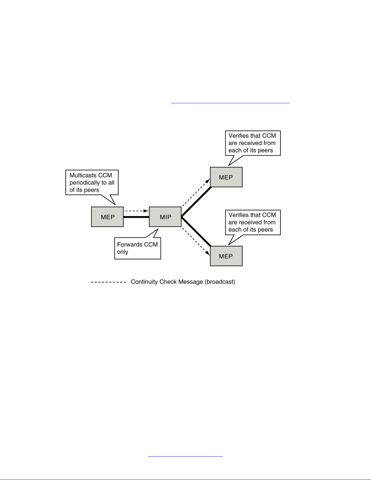
Each MEP periodically transmits multicast CCM. A CCM traverses all the bridges until it
reaches an MEP with the same (or, in an error situation, lower) MD level as the sending
MEP.
• drops frames received from the wire side
• processes frames received from the relay side
Important:
Secure Router 2330/4134 Release 10.1 supports Down MEPs only.
Each MEP maintains a list of its peers and expects to receive CCM from each of its peers
periodically. Each MEP maintains a list of “validity” or “lifetime” timers. There is one timer for
each peer (remote) MEP. All MEPs in a singe MA share one CCM transmit period (that is, you
configure the CCM timer only once for each MA). The IEEE 802.1ag standard defines the
Configuration — Layer 2 Ethernet July 2013 23
Page 24
Ethernet Connectivity Fault Management
"validity" or "lifetime" timer value as 3.5 times greater than the CCM transmit period of a MEP.
Receiving MEPs declare connectivity failures after missing three consecutive CCM from a
peer.
Additionally, transmitting MEPs encode the transmit period in the CCM interval field of the
CCM, which enables the receiving MEP to identify configuration errors and raise an appropriate
alarm. The transmission period is configurable for each MA. Use the cc-interval command to
define the transmission period (see
The following figure shows an MEP sending multicast CCM. Note that all MEPs transmit CCM,
not only the MEP for which the CCM path is shown.
Configuring Continuity Check Messages on page 61).
Figure 3: An MEP transmitting CCM
Fault verification and isolation
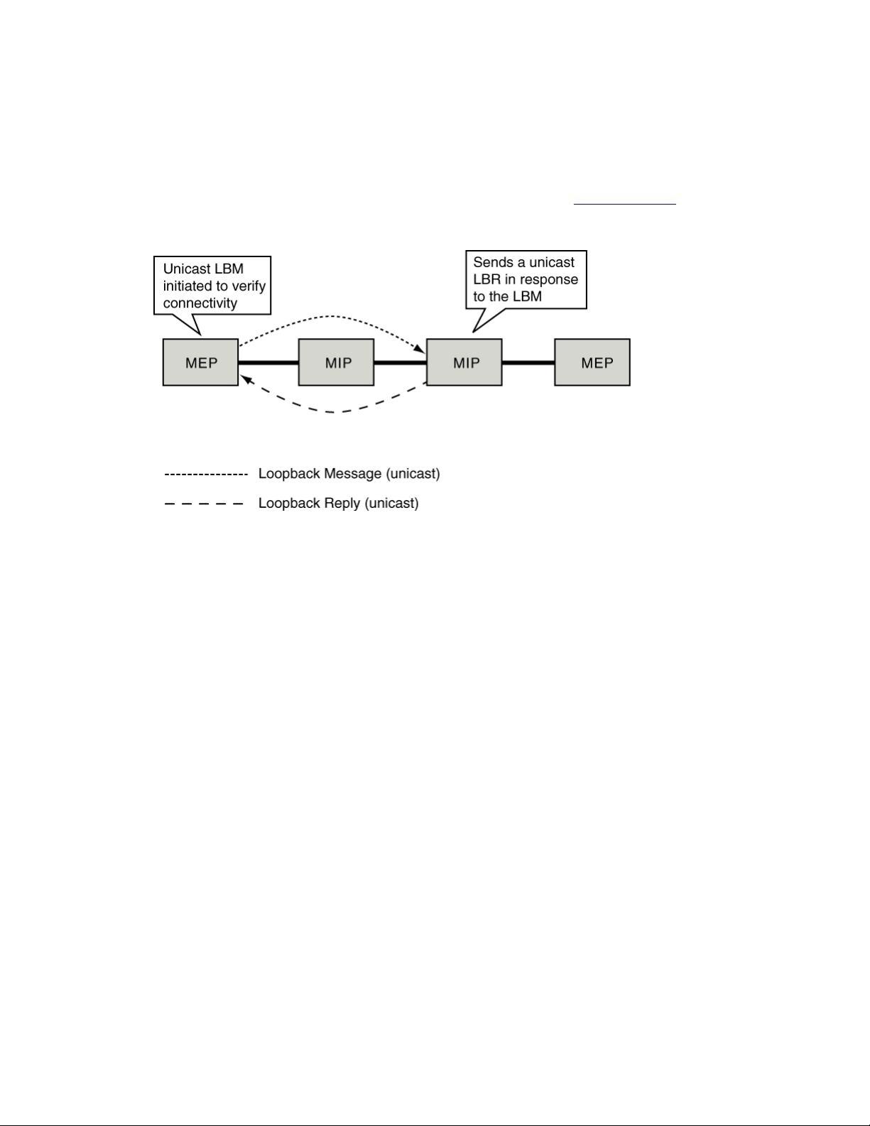
You can use Loopback Messages (LBM) for fault verification and fault isolation. The LBM is a
unicast message you can trigger with a command. LBM can be addressed to either an MEP
or an MIP, but only an MEP can initiate the LBM. You can address a destination MEP with
either its MAC address or its MEP ID, however you can address an MIP only by its MAC
address.
Addressing with the MEP ID is only possible if the MAC address of the remote MEP has
previously been learned. If you use the MEP ID as the address, and the MAC address of the
remote MEP is unavailable, the command fails. You must repeat the command using the MAC
address of the remote MEP.
24 Configuration — Layer 2 Ethernet July 2013
Comments? [email protected]
Page 25
Maintenance Domain
The destination MP responds with a Loopback Reply (LBR). When you issue the command to
send an LBM, the command becomes unavailable until the LBR is received or a timeout
occurs.
You use LBM to discover if the target MP is reachable. LBM does not provide hop-by-hop
discovery of a path. For hop-by-hop discovery of a path, see
The following figure shows the LBM and LBR.
Path discovery on page 25.
Figure 4: Loopback message and reply
Path discovery
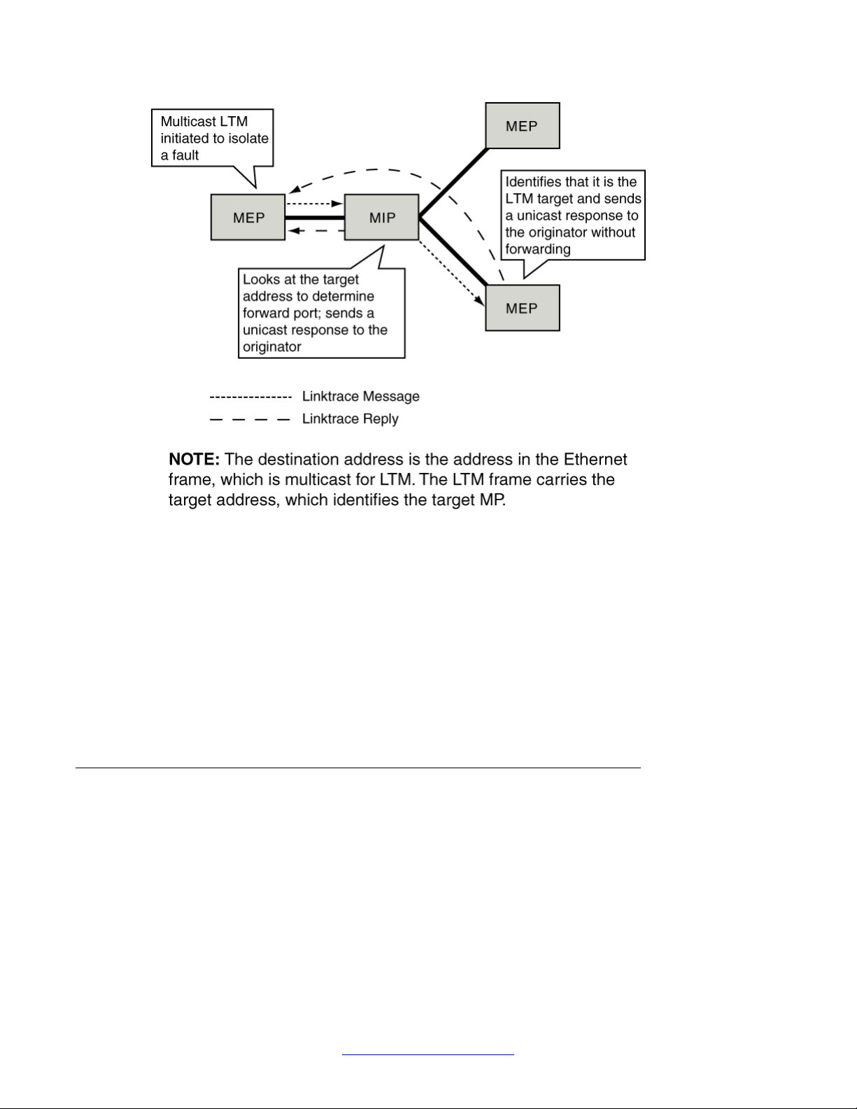
You use Linktrace Messages (LTM) for path discovery. An LTM is a multicast message that
an MEP generates. An LTM frame contains the MAC address of the target MP. The LTM is
intercepted by all MPs that are at the same level as the MEP initiating the LTM to the destination
MP (an LTM can be addressed to either an MEP or an MIP). Each MP that intercepts the LTM
looks at the target address. If the MP determines that it is not the target, the MP performs the
following three actions:
• decrements the “Time To Live” (TTL) field in the LTM frame
• sends a Linktrace Reply (LTR)
• forwards the original LTM to the destination
The LTR is a unicast message addressed to the originating MEP. The LTR is sent only after
a random time delay in the range of 0 to 1 second (as defined in the IEEE 802.1ag protocol).
The LTM is forwarded until it reaches its destination or the TTL value is decremented to 0.
The following figure shows the LTM and LTR.
Configuration — Layer 2 Ethernet July 2013 25
Page 26
Ethernet Connectivity Fault Management
Figure 5: Linktrace message and reply
You initiate the LTM with a command. When you issue the LTM command, the CLI gives the
session ID for that test and exits. The LTRs are appended to this session in the Linktrace cache
based on the transaction ID. Use the show cfm linktrace-cache <session-id>
command to view results.
Fault notification
The Secure Router 2330/4134 provides fault notification through CLI event messages and
error logs.
Maintenance Intermediate Point
MIPs are internal to an MD (that is, MIPs are never at the boundary of an MD). MIPs respond
to connectivity fault management frames only when triggered by linktrace and loopback
messages. MIPs are associated with an MD, and not with any specific MA. An MIP can
participate in connectivity fault management of one service instance, or an MIP can participate
in CFM of many service instances that have the same MD level as the MIP.
MIPs do not initiate any connectivity fault management messages. MIPs passively receive
connectivity fault management messages, process the messages received, and respond to
the originating MEP. By responding to received connectivity fault management messages,
26 Configuration — Layer 2 Ethernet July 2013
Comments? [email protected]
Page 27

MIPs help you to discover the hop-by-hop path between MEPs, which allows you to isolate
connection failures to smaller segments of the network and to discover the location of faults
along the paths.
You can create, enable, and disable MIPs independently of MEPs.
An MIP acts based on the relationship between the level assigned to the connectivity fault
management frame received and the level assigned to the MIP. The possible MIP actions are
the following:
• transparently forwards all connectivity fault management frames that have a higher or
lower MD level than the MIP
• processes frames that have the same MD level as the MIP
Connectivity Fault Management messages
CFM uses standard Ethernet frames distinguished by EtherType or (for multicast messages)
by MAC address. All connectivity fault management messages are confined to an MD. Secure
Router 2330/4134 supports the following connectivity fault management messages:
Maintenance Domain
• CCM—multicast heartbeat messages that MEPs periodically initiate. CCM provide the
following services:
- allow MEPs to discover other MEPs within an MA of a domain
- allow MIPs to discover MEPs
You configure CCM for an MA within a domain, or you configure CCM for a VLAN.
• Loopback messages—unicast frames transmitted by an MEP. Loopback messages are
similar to an Internet Control Message Protocol (ICMP) ping message. You initiate a
loopback message to verify connectivity to a particular MP, which indicates if a destination
is reachable.
• Linktrace messages—multicast frames transmitted by an MEP. CFM linktrace messages
are similar to User Datagram Protocol (UDP) linktrace messages. The administrator
initiates a linktrace message to track the path (hop-by-hop) to a destination MEP.
Configuration — Layer 2 Ethernet July 2013 27
Page 28

Ethernet Connectivity Fault Management
Connectivity Fault Management modes
The Secure Router 2330/4134 supports the following CFM modes:
• Routed mode, in which Secure Router 2330/4134 sends and receives untagged CFM
frames.
• Switched mode, which is, more specifically, one of the following:
- Access mode – Secure Router 2330/4134 can receive both VLAN tagged and
untagged CFM frames, but can send only untagged CFM frames.
- Hybrid mode – Secure Router 2330/4134 can receive both VLAN tagged and
untagged CFM frames. There are two options for sending CFM frames:
• Egress tagged – sends VLAN tagged CFM frames
• Egress untagged – sends untagged CFM frames
- Trunk mode – Secure Router 2330/4134 can receive and send only VLAN tagged
CFM frames.
Connectivity Fault Management errors and statistics
The heartbeat mechanism of CFM (using periodic CCM) makes it possible to detect a number
of errors and accumulate data for statistical purposes.
Inconsistent configuration of the devices in an MD or an MA, or inconsistent configuration of
the MEPs, remote MEPs, and so on in different nodes of the network can result in configuration
errors. The Secure Router 2330/4134 stores configuration errors in a database.
You use the show commands to view the information stored in the databases.
The databases contain data for each MEP in the Secure Router 2330/4134.
28 Configuration — Layer 2 Ethernet July 2013
Comments? [email protected]
Page 29

Chapter 5: Layer 2 fundamentals
Ethernet is one of the most widely deployed Layer 2 Local Area Network (LAN) transport technologies
today. A LAN is a data communications network connecting terminals, computers, and printers within a
building or other geographically limited area. Advantages of Ethernet include:
• Ability to scale in bandwidth and speed — Ethernet switches support high port densities and
forwarding rates in the millions of packets per second
• Support of Class of Service (CoS) that allows up to eight classes of service to be defined
• Ease of deploying multipoint communications
The Avaya Secure Router 2330/4134 Ethernet Layer 2 features support VLAN MAC bridging of traffic
within the LAN, and between LAN to WAN for traffic in and out of the carrier network. The Secure Router
2330/4134 platform uses both the hardware network processor and software forwarding logic for Ethernet
Layer 2 switching. The network processor handles LAN switching. Software forwarding works with the
network processor to achieve LAN to WAN (and WAN to LAN) data switching. The Secure Router
2330/4134 also supports termination of Layer 3 traffic on a VLAN to achieve routing using the Layer 3
engine.
Layer 2 switching and bridging
Local Area Network (LAN) is a data communications network connecting terminals, computers
and printers within a building or other geographically limited areas. These devices could be
connected through wired cables or wireless links. Ethernet and Token Ring are examples of
standard LAN technologies. LAN switching involves examining physical network addresses
that uniquely identify a device in the network.
LAN bridging offers an extension of the LAN by supporting the connection of multiple LAN
segments. MAC addresses of the datagram that flow through bridges are examined to build a
table of known destinations. If the destination of a datagram is on the same segment as the
source of the datagram, the bridge drops the datagram because forwarding is not required.
However, if the destination is on another segment, the bridge transmits the datagram on that
segment only. If the bridge does not know the destination segment, it transmits the datagram
on all segments except the source segment (a technique known as flooding).
MAC bridging
MAC Bridging allows multiple LANs to be connected together. Transparent bridging involves
the creation of MAC address tables, and limits the Ethernet collision domain by filtering data
Configuration — Layer 2 Ethernet July 2013 29
Page 30

Layer 2 fundamentals
sent between LAN segments. This reduces network congestion and allows networks to be
partitioned for administrative purposes.
VLANs
A Virtual LAN (VLAN) is a switched network that is logically segmented on an organizational
basis, by functions, project teams, or applications rather than on a physical or geographical
basis. VLAN segments the physical local-area network (LAN) infrastructure into different
subnets so that packets are switched only between ports within the same VLAN. Devices on
a VLAN are configured so that they can communicate as if they were attached to the same
physical wire, when in fact they are located on a number of different LAN segments. With VLAN
partitioning, traffic stays within the appropriate groups, minimizing wasteful broadcasts.
A VLAN is made up of a group of ports that define a logical broadcast domain. These ports
can belong to a single device, or they can be spread across multiple devices. In a VLAN-aware
device, every frame received on a port is classified as belonging to one and only one VLAN.
Whenever a broadcast, multicast, or unknown destination frame must be flooded by a VLANaware device, the frame is sent out only through all the other active ports that are members of
this VLAN.
The default device configuration groups all ports into the port-based default VLAN 1. This VLAN
cannot be deleted from the system.
The Secure Router 2330/4134 supports port-based and protocol-based VLANs.
A port-based VLAN is a VLAN whose ports are explicitly configured as members. In port-based
VLANs, all ports are always static members. When creating a port-based VLAN, you assign a
VLAN identification number (VID) and specify which ports belong to the VLAN. The VID is used
to coordinate VLANs across multiple devices.
Protocol-based VLANs are an effective way to segment your network into broadcast domains
according to the network protocols in use. Traffic generated by any network protocol can be
automatically confined to its own VLAN.
VLAN tagging is a MAC option. A VLAN-tagged frame is a basic MAC data frame that has had
a 4-byte VLAN header inserted between the SA and Length/Type fields. The VLAN header
consists of the following fields:
• A reserved 2-byte type value, indicating that the frame is a VLAN frame
• Tag Protocol Identifier (TPID) - defined value of 8100 in hex. When a frame has the
EtherType equal to 8100, this frame carries the tag IEEE 802.1Q/802.1P.
• TCI - Tag Control Information field including user priority, Canonical format indicator and
VLAN ID.
VLAN tagging can be enabled or disabled on each interface.
The Secure Router 2330/4134 uses IEEE 802.1Q tagging of frames and coordinates VLANs
across multiple devices. The following figure shows the additional 4-octet (tag) header that is
inserted into a frame after the source address and before the frame type. The tag contains the
VLAN ID associated with the frame.
30 Configuration — Layer 2 Ethernet July 2013
Comments? [email protected]
Page 31

VLANs
Figure 6: VLAN tagging
In the Secure Router 2330/4134, your port level configuration determines whether tagged
frames are sent and received. Tagging is set as true or false for the port and is applied to all
VLANs on that port.
The Secure Router 2330/4134 associates a frame with a VLAN based on the data content of
the frame and the configuration of the destination port. Whether the frame is tagged or
untagged dictates how that frame is treated.
A Secure Router 2330/4134 port with tagging enabled sends frames explicitly tagged with a
VLAN ID. Tagged ports are typically used to multiplex traffic belonging to multiple VLANs to
other IEEE-802.1Q-compliant devices. If tagging is disabled on a Secure Router 2330/4134
port, it does not send tagged frames. An untagged port connects a Secure Router 2330/4134
to devices that do not support IEEE 802.1Q tagging. If a tagged frame is forwarded out a port
on which tagging is set to false, the device removes the tag from the frame before sending it
out the port.
If a tagged frame is received on a tagged port, with a VLAN ID specified in the tag, the Secure
Router directs it to that VLAN, if it is present.
For untagged frames, VLAN membership is implied from the content of the frame itself. For
untagged frames received on a tagged port, you can configure the port to either discard or
accept the frame. If you configure a tagged port to accept untagged frames, the port must be
assigned to a port-based VLAN.
Independent VLAN learning
In the Secure Router 2330/4134, each VLAN has its own, independent, forwarding database.
That is, the same MAC address can be learned in different VLANs; and, based on the VLAN
receiving traffic for this address, the device is able to forward to this MAC address without any
confusion. This means that before the device can look up the source or destination MAC
address in a received frame, or before it can decide whether to bridge or to route a frame, it
must first determine to which VLAN the frame belongs.
Independent VLAN learning mode is used to learn MAC addresses in the context of the VLAN
to which they belong.
Configuration — Layer 2 Ethernet July 2013 31
Page 32

Layer 2 fundamentals
Static multicast MAC filtering
Some network applications, such as mirroring, rely on a Layer 2 multicast MAC mechanism to
send a frame to multiple hosts for processing. Multicast MAC filtering lets you direct MAC
multicast flooding to a specific set of ports.
In Layer 2, a multicast MAC address generally floods to all ports in the VLAN. With multicast
MAC filtering, you can define a separate flooding domain for a given multicast MAC address,
which is a subset of the ports on a VLAN.
To perform multicast MAC filtering, you create the VLAN normally and then manually define a
flooding domain (that is, MAC address and port list) for a specific multicast address. When
specifying the multicast MAC flooding domain, indicate which ports or link aggregation groups
are to be considered for multicast traffic. The actual flooding is then based on whether the
specified ports are active members in the VLAN.
VLAN classification
Each frame received by a VLAN bridge is classified as belonging to exactly one VLAN by
associating a VID value with the received frame. The classification is achieved as follows:
1. If the vlan_identifier parameter carried in a received data indication is the null VLAN
ID (VID), and no VLAN classification rules are configured, then the VID for the frame
is the unique Port VLAN ID (PVID) associated with the port through which the frame
was received. Otherwise:
2. If the vlan_identifier parameter carried in a received data indication is the null VLAN
ID and there are VLAN classification rules configured, then the VID for the frame is
selected from the VID set of the port through which the frame was received. The
VID selected is the member of the VID set for which the associated Protocol Group
Identifier (PGI) is equal to the PGI of the frame. If no matches are found, then the
VID for the frame is the PVID associated with the port. Otherwise:
3. The VID for the frame is the vlan_identifier parameter value.
Important:
The vlan_identifier parameter carries the null VLAN ID if the frame was not VLAN tagged.
There are two cases: either the frame was untagged, or the frame was tagged and the tag
header carried a VID value equal to the null VLAN ID (that is, a priority-tagged frame).
Supported protocols for protocol-based VLAN classification rules
The following table lists the protocols that the Secure Router 2330/4134 supports for VLAN
classification rules.
32 Configuration — Layer 2 Ethernet July 2013
Comments? [email protected]
Page 33

Table 3: Supported protocols for VLAN classification rules
Classification rule parameter Description
ipv4 IPv4
ipv6 IPv6
mpls MPLS
arp ARP
rarp Reverse ARP
vlan-tagged 802.1q VLAN tag
appletalk Appletalk
ipx IPX
pppoe-disc PPPoE discovery
pppoe-session PPPoE session
The supported encapsulations for protocol-based VLAN classification rules are:
VLANs
• Ethernet Type II
• LLC SNAP
• LLC only
VLAN stacking
VLAN stacking refers to the encapsulation of one VLAN within another VLAN. A stacked VLAN
transparently tunnels packets through the stacked VLAN domain by adding an additional 4byte header to each packet.
Stacked VLANs offer the following features:
• VLAN transparency for IEEE 802.1Q tagged or untagged traffic through a service provider
core network
• A solution to VLAN scalability issues—you can summarize customer VLANs into core
stacked VLANs
• Uses a layered architecture to improve scalability
Multiple IP Helper Addresses on a VLAN
The Secure Router 2330/4134 supports multiple IP Helper addresses on a VLAN. The Multiple
IP Helper feature assists in broadcasting network traffic between client machines and servers
residing on different subnets. There are situations in which a user can want to control which
Configuration — Layer 2 Ethernet July 2013 33
Page 34

Layer 2 fundamentals
broadcast packets and protocols should be forwarded by the router. The Multiple IP Helper
feature provides this functionality.
Multiple IP Helper is useful when UDP broadcasts are sent to a DNS server by a network host.
If the network host happens to reside on a segment without a DNS server, the UDP broadcast
fails. A helper address is configured and a protocol assigned to an interface. The exceptions
to this are DHCP and BOOTP broadcasts, which are handled by DHCP Relay.
The Multiple IP Helper feature is implemented on primary ethernet interfaces and VLANenabled ethernet sub-interfaces, with a maximum of six helper addresses can be configured
for each interface.
Spanning Tree Protocol
The operation of the Spanning Tree Protocol (STP) is defined in the IEEE Standard 802.1D.
The STP detects and eliminates logical loops in a bridged or switched network. When multiple
paths exist, the spanning tree algorithm configures the network so that a bridge or switch uses
only the most efficient path. If that path fails, the protocol automatically reconfigures the
network to make another path active. The process maintains network operations. You can
control path redundancy for VLANs by implementing STP.
Multiple Spanning Tree Protocol
The Secure Router 2330/4134 supports Multiple Spanning Tree Protocol (MSTP), and it is
enabled by default. MSTP on the Secure Router 2330/4134 is backward-compatible with STP
and Rapid Spanning Tree Protocol (RSTP). STP and RSTP can be implemented on a per-port
basis on the Secure Router 2330/4134.
MSTP defines an extension to RSTP that further develops the usefulness of VLANs. This "perVLAN" MSTP configures a separate Spanning Tree for each VLAN group and blocks the links
that are redundant within each Spanning Tree.
If there is only one VLAN in the network, single (traditional) STP works appropriately. If the
network contains more than one VLAN, the logical network configured by single STP would
work, but it is possible to make better use of the redundant links available by using an alternate
spanning tree for different (groups of) VLANs. MSTP allows the formation of MST regions that
can run multiple MST instances (MSTI). Multiple regions and other STP bridges are
interconnected using one single common spanning tree (CST).
MSTP on the Secure Router 2330/4134 interoperates with Cisco’s implementation of MSTP.
The Cisco equipment must have IOS v12.2 (25), or newer, installed.
34 Configuration — Layer 2 Ethernet July 2013
Comments? [email protected]
Page 35
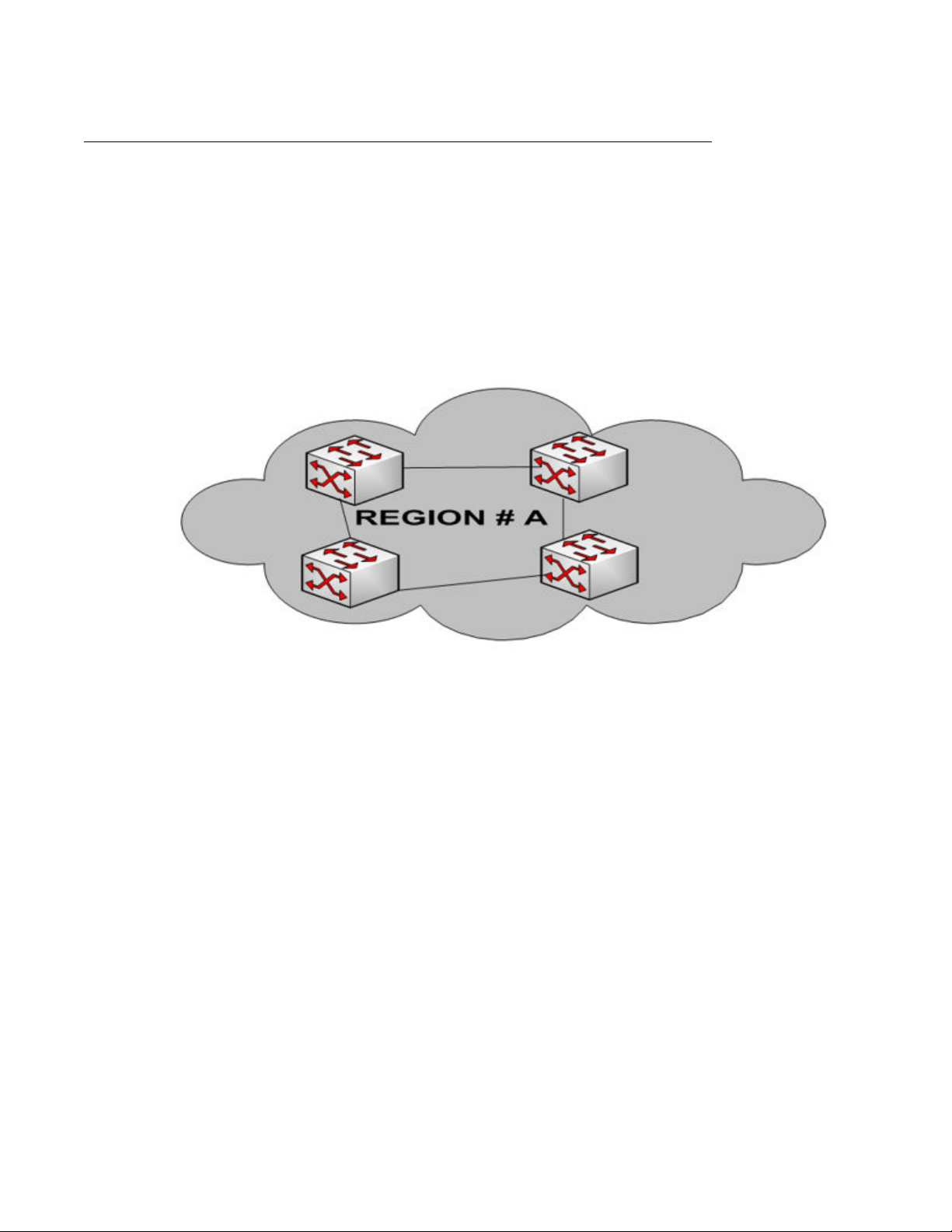
MSTP regions
All devices are said to be in the same region if the following three elements are the same on
all the devices:
• region name (32 bytes)
• revision number (2 bytes)
• configuration digest (the numerical value derived from VLAN to instance mapping)
The following figure shows a single MSTP region.
Spanning Tree Protocol
Figure 7: Single MSTP region
Within a region, there can be multiple spanning trees running for an instance.
All the bridges within a region appear as a single bridge to other regions. Bridges that are
outside the region always have a single point of contact to the region.
The following figure shows the relationship amongst multiple MSTP regions.
Configuration — Layer 2 Ethernet July 2013 35
Page 36
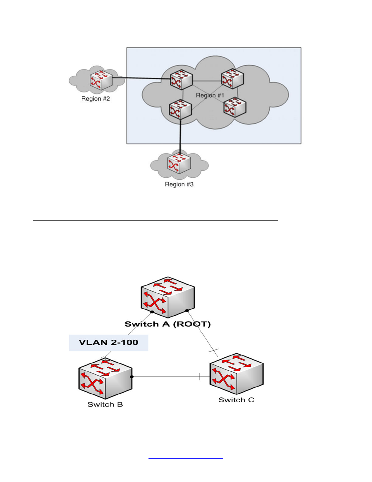
Layer 2 fundamentals
Figure 8: Multiple MSTP regions
Common Spanning Tree
With Common Spanning Tree (CST) there is only one instance of spanning tree for all VLANs.
As shown in the following figure, the traffic for all VLANs (2–100) must travel from Switch B to
Switch A, while the path between Switch C and Switch A is unused.
Figure 9: Common Spanning Tree
36 Configuration — Layer 2 Ethernet July 2013
Comments? [email protected]
Page 37
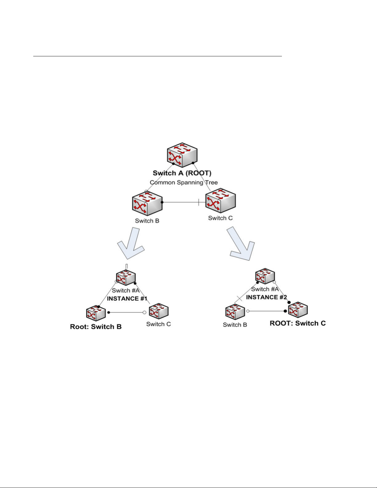
MSTP instance
With MSTP instances, traffic can be load-balanced between all the links. Within a region, each
instance has its own independent spanning tree. It can have its own root bridge. Each bridge
can have a different priority for each instance, so that the bridge can be selected as root in one
instance and non-root in another instance.
In the following figure, Switch B is root in Instance #1. Switch C is the root bridge in Instance
#2. In CST, Switch A is the root.
Spanning Tree Protocol
Figure 10: Network with multiple instances configured
VLANs can be assigned arbitrarily to any instance. Any VLAN can be part of one and only one
instance. The VLAN traffic inside the MSTP region takes the path determined by the Spanning
Tree associated with that particular instance. For example, if VLANs 2–50 are associated with
Instance #1 and VLANs 51–100 are associated with Instance #2, the VLAN traffic (VLAN ID
2–50) never takes the link AC path until and unless the link AB or BC fails. Similarly, the VLAN
traffic (VLAN ID 51–100) never takes the link AB path until and unless link CB or CA fails.
Configuration — Layer 2 Ethernet July 2013 37
Page 38
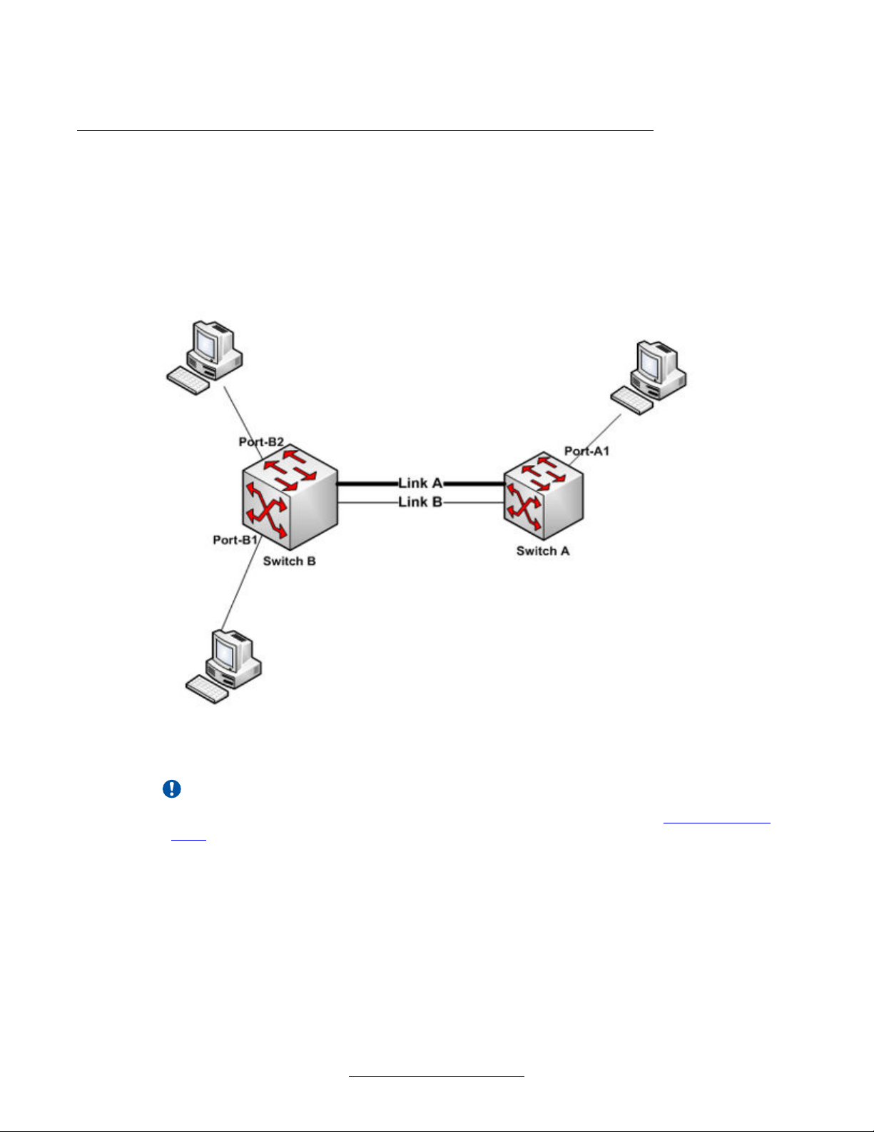
Layer 2 fundamentals
Rapid transitions
On a port connected to no other bridge, Spanning Tree PortFast brings the port up more quickly
following device initialization or a spanning tree change.
For example, in the following figure, ports A1, B1, B2 are connected to end stations. These
ports do not participate in the Spanning Tree port selection. These ports can, therefore, go
directly to the spanning tree forwarding state (skipping the listening and learning states).
Figure 11: Enabling rapid transitions in a network
Important:
Enabling PortFast does not disable spanning tree on an interface. See
PortFast BPDU
Filter on page 39 for more information.
PortFast is intended for access ports where only one device is connected to the router or switch
(as in workstations with no other spanning tree devices). If you configure PortFast on a port
that is connected to another bridge, there is the possibility of forming a loop. This can be
prevented with the help of the Bridge Protocol Data Unit (BPDU) Guard feature.
38 Configuration — Layer 2 Ethernet July 2013
Comments? [email protected]
Page 39

PortFast BPDU Guard
The PortFast BPDU Guard feature prevents loops by moving a port into an "error disable" state
when that port receives a BPDU. When you enable the BPDU guard feature on the port,
Spanning Tree shuts down PortFast-configured interfaces that receive BPDUs, rather than
putting them into the Spanning Tree blocking state.
In a valid configuration, PortFast-configured interfaces do not receive BPDUs. If a PortFastconfigured interface receives a BPDU, an invalid configuration exists, such as the connection
of an unauthorized device.
PortFast BPDU Filter
By default, MSTP sends BPDU packets on all ports regardless of whether or not you have
enabled PortFast. Enabling PortFast BPDU filter on a port results in the following:
• stops sending BPDU packets
• stops processing of incoming BPDU packets
IGMP Snooping
• sets the port to forwarding always
The purpose of the PortFast BPDU Filter command is to filter all incoming BPDUs on an
interface, which effectively disables spanning tree on an interface. You can apply the feature
on ports that connect to an end station or to routers. Although spanning tree is disabled, all
Layer 2 forwarding rules remain the same (in terms of packet flooding within a VLAN domain,
or in terms of supporting VLAN termination) to allow routing of Layer 2 packets.
IGMP Snooping
The Internet Group Management Protocol (IGMP) is a Layer 3 protocol used by IP hosts to
report multicast information to neighboring multicast routers.
IGMP Snooping allows a Layer 2 device to read (snoop) IGMP packets transferred between
IP multicast routers and IP multicast hosts to learn the IP multicast group membership. IGMP
Snooping allows the Layer 2 device to forward group-specific multicast traffic only to ports that
are members of that group. IGMP Snooping dynamically determines to which ports to send
specific multicast group traffic. Without IGMP Snooping, multicast traffic is forwarded to all
ports. IGMP Snooping drops all but one of the host "join" messages for each multicast group
and forwards only this one "join" message to the multicast router when proxy is enabled, which
reduces the number of IGMP messages exchanged between IP multicast routers and hosts.
The Secure Router 2330/4134 IGMP Snooping feature supports both IGMPv1 and IGMPv2.
IGMPv3 packets are silently discarded. Avaya recommends that in a network where IGMPv3
and IGMPv2 hosts co-exist, you configure the multicast router to send IGMPv2 messages so
that all hosts communicate using IGMPv2.
Configuration — Layer 2 Ethernet July 2013 39
Page 40

Layer 2 fundamentals
If IGMP Snooping is disabled, the Secure Router 2330/4134 handles IP multicast traffic in the
same manner as broadcast traffic (forwards frames received on one interface to all other
interfaces). Without IGMP Snooping, there is excessive traffic on the network, which negatively
impacts network performance. IGMP Snooping allows the Secure Router 2330/4134 to monitor
network traffic and to determine which hosts will receive multicast traffic.
For information on how to configure IGMP snooping, see Avaya Secure Router 2330/4134
Configuration — IPv4 Multicast Routing, (NN47263-504).
IGMP proxy
IGMP proxy allows the router to function as proxy for the hosts that are attached downstream
of the router. Upon receiving a query from a multicast router, a proxy-enabled router sends the
reports for all the group MAC addresses it has learned, instead of forwarding the reports to its
ports. When the router learns a new group MAC address, the report is forwarded to all multicast
router interfaces.
When the router receives a leave message from downstream hosts, the protocol data unit
(PDU) is forwarded to all multicast routes.
IGMP querier
You can configure the Secure Router 2330/4134 as a querier or non-querier. The querier
feature allows the Secure Router 2330/4134 to solicit membership information faster.
When you enable the querier feature on a VLAN, the Secure Router initiates IGMP general
queries to all the ports in that VLAN. However, when the Secure Router receives any IGMP
general query from other routers or switches on a VLAN, the querier functionality is
automatically disabled. The Secure Router 2330/4134 remains in the non-querier state as long
as it keeps receiving queries from outside. If no query is received for a period of time that
equals the query interval (the default value is 125 seconds), then the querier functionality is
enabled automatically.
Query interval
The query interval is the time interval between two queries sent by the Secure Router
2330/4134 when the IGMP Snooping querier feature is enabled. The range of query interval
is between 125000 milliseconds and 300000 milliseconds. The default value is 125000
milliseconds. The query interval is also used to calculate the group membership timer interval
and other querier timer interval as follows (IGMPv2 standard):
• Group membership timer interval—The "group membership interval" is the amount of time
that must pass before which an IGMP Snooping module decides there are no more
40 Configuration — Layer 2 Ethernet July 2013
Comments? [email protected]
Page 41

IGMP Snooping
members of a group on a VLAN. Use the following formula to calculate the group
membership timer interval value:
- Group membership timer interval = ((2 x query interval) + maximum response time)
• Other querier timer interval—The "other querier timer interval" is the amount of time that
must pass before which an IGMP Snooping module decides that there is no longer
another multicast router that should be the querier in a VLAN. When the IGMP Snooping
module stops receiving external queries on a VLAN, the module waits for the next query
for a period of time that equals the other querier timer interval. If the module does not
receive any query within this duration of time, the module assumes there is no other
querier present in the VLAN and removes the dynamically-learned mrouter port. If the
querier feature is enabled on the VLAN, the querier feature starts generating general
query packets to all the ports in the VLAN. Use the following formula to calculate the other
querier timer interval value:
- Other querier interval = ((2 x query interval) + (maximum response time)/2)
For example, if the query interval is set to 200 seconds (200000 milliseconds [ms]), and the
maximum response time is set to 10 seconds, then you can calculate the following:
• Group membership timer interval = ((2 x 200 seconds) + 10 seconds) = 410 seconds
• Other querier timer interval = ((2 x 200 seconds) + (10 seconds/2)) = 405 seconds
Last member query interval
The "last member query interval" is the maximum response time inserted into group-specific
queries sent in response to "leave group" messages, and is also the amount of time between
group-specific query messages. The range of values for the last member query interval is 1000
– 25500 ms. The default value is 1000 ms. The last member query interval value can be
configured to modify the "leave latency" of the network. A reduced value results in reduced
time to detect the loss of the last member of a group.
Maximum response time
The maximum response time is inserted into the periodic general queries sent by a querier.
You can control the burstiness of IGMP messages on the subnet by varying the maximum
response time. For example, larger values make the IGMP message traffic less bursty because
the host responses are spread out over a larger interval. The number of seconds for the
maximum response time must be less than the query Interval.
Fast-leave processing
You can configure the Secure Router 2330/4134 to perform fast-leave processing.
Configuration — Layer 2 Ethernet July 2013 41
Page 42

Layer 2 fundamentals
If fast-leave processing is not enabled, when a device receives a "leave group" message for
a group that has members on the host interface, the device sends group-specific queries to
the host for the group being left. The group-specific queries have a maximum response time
set to a "last member query" interval. If no "join" reports are received within the maximum
response time, the device assumes there are no local members in this group and sends a
"leave" report to the multicast router (if available).
When a device receives a "leave group" message with fast-leave processing enabled, the
device does not send group-specific queries to the host. The device immediately updates its
own database and sends a "leave report" to the multicast router if there are no other members
for the group. Fast-leave processing helps stop the multicast traffic flow to the host after
receiving a "leave report".
Multicast router ports
Any Layer 2 port of a Secure Router 2330/4134 can become a multicast router (mrouter) port.
When a port receives an IGMP v1/v2 general query, that port is marked as an mrouter port. If
the Secure Router 2330/4134 stops receiving queries for a specific period of time, the
dynamically-learned mrouter port is removed. This period of time varies based on the
configured IGMP Snooping "query interval" and "maximum response time" settings.
GVRP
You can also specify that an mrouter port be static. The static mrouter port configuration
overrides a dynamic entry.
Generic Attribute Registration Protocol (GARP) VLAN Registration Protocol (GVRP) is an
application defined in the IEEE 802.1Q standard that allows routers to exchange VLAN
information in a network.
GVRP:
• runs only on 802.1Q trunk links
• prunes trunk links so that only active VLANs will be sent across trunk connections. GVRP
ports run in various modes to control how they will prune VLANs.
• expects to hear join messages from the routers or switches before it will add a VLAN to
the trunk
• updates and hold timers can be altered
• can be configured to dynamically add and manage VLANs to the VLAN database for
trunking purposes
42 Configuration — Layer 2 Ethernet July 2013
Comments? [email protected]
Page 43

Link aggregation
Link Aggregation allows one or more links to be aggregated together to form a Link Aggregation
Group (LAG), such that a MAC Client can treat the Link Aggregation Group as if it were a single
link. This allows for faster connections between devices managed as a single connection, load
sharing and load balancing among the individual links within a logical connection, and a failure
mechanism that allows a link to stay up at a reduced peak rate even if some of the physical
ports go out of service.
The Secure Router 2330/4134 supports IEEE 802.3ad-based link aggregation, which, through
the Link Aggregation Control Protocol (LACP), supports a dynamic link aggregation function
that can add links dynamically, as they become available, to a trunk group.
LACP
IEEE 802.3ad-based (IEEE 802.3 2002 clause 43) link aggregation allows you to aggregate
one or more links together to form a link aggregation group (LAG), such that a MAC client can
treat the LAG as if it were a single link.
Link aggregation
LACP dynamically detects whether links can be aggregated into a link aggregation group and
does so when links become available. The main purpose of LACP is to manage device ports
and their port memberships to form link aggregation groups (LAG). LACP can dynamically add
or remove LAG ports, depending on their availability and states.
Aside from automatic link aggregation, a side benefit of LACP is its ability to detect link layer
failure within a service provider network. LACP packets are exchanged end-to-end. Therefore,
if a link in the middle fails and the local ports do not register the failure, LACP times out and
disables the port for traffic.
Load balancing is achieved based on the following prerequisites:
• The MAC addresses of the received packets must be Known Unicast.
• The algorithm is based on 5-tuples, therefore a uniformly changing src mac, dest mac,
src IP, dest IP, and protocol leads to more balanced traffic distribution.
Port mirroring
The Secure Router 2330/4134 has a port mirroring feature that helps you to monitor and
analyze network traffic. The monitoring (destination) port can be connected to a network
analyzer or RMON probe for packet analysis. Unlike other methods that are used to analyze
packet traffic, the packet traffic is uninterrupted and packets flow normally through the mirrored
port.
Configuration — Layer 2 Ethernet July 2013 43
Page 44

Layer 2 fundamentals
The port mirroring feature supports both ingress (incoming traffic) and egress (outgoing traffic)
port mirroring. When port mirroring is enabled, the ingress or egress packets of the mirrored
(source) port are forwarded normally and a copy of the packets is sent out of the mirrored port
to the mirroring (destination) port.
To avoid seeing unintended traffic, remove mirroring (destination) ports from all virtual local
area networks (VLAN) and multiple spanning tree instances (MSTIs). When mirroring ports
where VLAN tagging is enabled, the VLAN tags are not included in the packets received at the
mirroring (destination) port.
The port mirroring feature is supported only on the module Ethernet ports. You can configure
a maximum of one analyzer (destination) port for each module.
Selectable range of ports
With Release 10.2 and later, you can specify a range of Ethernet ports to configure at the same
time. To do so, you must use the interface range ethernet command.
44 Configuration — Layer 2 Ethernet July 2013
Comments? [email protected]
Page 45

Chapter 6: Power over Ethernet
configuration
Use the procedures in this section to configure Power over Ethernet (PoE).
Configuring the PoE port mode
Use the procedure in this section to configure PoE port modes.
Procedure steps
1. To access configuration mode, enter:
configure terminal
2. To specify the PoE port mode, enter:
poe portmode <slot/port> <mode>
Table 4: Variable definitions
Variable
<mode> Specifies the port mode. Valid values for
mode are 1 to 3 (1=auto; 2=static; 3=never.
The default value for mode is 1.
• Auto mode: Enables port power on the
specified port (with a power limit of 16 W).
If you set the port to auto mode, then port
power is enabled to the port, and the
default power of 16 W (maximum) can be
supplied to the device connected to the
specified port.
• Static mode: Sets the power limit for the
specified port to 16 W and enables power
on the port. After setting the port mode to
"static", you can set the port power limit in
the range of 37 to 16000 milliwatts (mW)
using the poe portpowerlimit
command.
• Never mode: Disables power on the
specified port until you change the mode to
Value
Configuration — Layer 2 Ethernet July 2013 45
Page 46
Power over Ethernet configuration
Variable Value
<slot/port> Specifies the slot and port number that
either "auto" or "static". Port power is
always disabled in "never" mode.
Use the no poe portmode <slot/
port> <mode> command to reset the port
mode to the default value of "auto".
You can enable or disable port power at any
time using the poe portpower command
for ports configured in either auto mode or
static mode.
Important:
When the system comes up for the first
time, power is disabled for safety reasons,
even though ports are in auto mode.
identify the port to configure. Valid values for
slot are 5 to 7. Valid values for port are 1 to
24.
Configuring PoE port power
Use the procedure in this section to enable power on a port.
Procedure steps
1. To access configuration mode, enter:
configure terminal
2. To enable power on a port, enter: poe portpower <slot/port>
Table 5: Variable definitions
Variable
<slot/port> Specifies the slot and port number that
Value
identify the port to configure. Valid values for
slot are 5 to 7. Valid values for port are 1 to
24.
• poe portpower <slot/port>
enables power on port <slot/port>. You can
configure this only when the mode of
operation is "auto" or "static" mode. If you
use this command when the mode of
operation is "never", the command has no
46 Configuration — Layer 2 Ethernet July 2013
Comments? [email protected]
Page 47

Configuring PoE port priority commands
Variable Value
impact on the system configuration. For
ports that are in "auto" or "static" mode, the
port power is enabled and powered
devices connected to these ports receive
power.
• no poe portpower <slot/port>
disables power on port <slot/port>. You
can configure this only when the mode of
operation is "auto" or "static" mode. If you
use this command when the mode of
operation is "never", the command has no
impact on the system configuration. For
ports that are in "auto" or "static" mode, the
port power is disabled and powered
devices connected to these ports do not
receive power.
The default value is power disabled on all 24
ports of a PoE card.
Configuring PoE port priority commands
Use the procedure in this section to configure the priority of PoE ports. When available power
falls below the configured value, the lowest priority ports are shut down first.
Procedure steps
1. To access configuration mode, enter:
configure terminal
2. To configure PoE port priority, enter:
poe portpriority <slot/port> <port priority>
Table 6: Variable definitions
Variable
<port priority> Specifies the slot and port number that
identify the port to configure. Valid values for
slot are 5 to 7. Valid values for port are 1 to
24.
<slot/port> Valid values for <port priority> are in the
range of 1 to 3 (1=critical; 2=high; 3=low).
The default value for port priority is 3.
Value
Configuration — Layer 2 Ethernet July 2013 47
Page 48

Power over Ethernet configuration
Variable Value
Use the no poe portpriority
<slot/port> <port priority>
command to reset the port priority to the
default value (3). This command also
removes the port priority configuration for
this port from the running configuration.
Configuring PoE device detection
Use the procedure in this section to enable 802.3af-compliant device detection.
Procedure steps
1. To access configuration mode, enter:
configure terminal
2. To enable 802.3af-compliant device detection, enter:
poe detect3af <slot>
Table 7: Variable definitions
Variable
<slot> Specifies the slot in which the interface
module is installed on which you enable
802.3af-compliant device detection. Valid
values for <slot> are 5, 6, and 7. When
disabled, both 802.3af compliant devices
and legacy devices are detected.
For example, if you configure poe
Value
detect3af <5>, only legacy devices are
detected in the ports of the module inserted
in slot 5.
Use the no poe detect3af <slot>
command to disable 802.3af detection for the
module in slot <slot>.
802.3af is disabled by default.
Configuring PoE port power limits
Use the procedure in this section to configure PoE port power limits.
48 Configuration — Layer 2 Ethernet July 2013
Comments? [email protected]
Page 49
Viewing PoE information
Procedure steps
1. To access configuration mode, enter:
configure terminal
2. To configure the PoE port power limit, enter:
poe portpowerlimit <slot/port> <power limit>
Table 8: Variable definitions
Variable Value
<power limit> Specifies the power limit for a port that is in
static mode. Valid values for the power limit
are 37 to 16000 milliwatts (mW). The default
value is 16000 mW (that is, 16 W).
Use no poe portpowerlimit
<slot/port> <power limit> reset
the power limit to the default value (16000
mW).
<slot/port> Specifies the slot and port number that
Viewing PoE information
Use the procedure in this section to view information related to PoE configuration.
Procedure steps
Important:
The power limit is set with an accuracy of
100mW. For example, if the power limit is
set to any value in the range 37 to 99, the
power limit is set to 0. If the power limit is
set to any value in the range 100 to 199,
the power limit is set to 100 mW. If the
power limit is set to any value in the range
15900 to 15999, the power limit is set to
15900 mW.
identify the port to configure. Valid values for
slot are 5 to 7. Valid values for port are 1 to
24.
1. To view information about the priority and power limit configured for the port, enter:
Configuration — Layer 2 Ethernet July 2013 49
Page 50

Power over Ethernet configuration
show poe portconfig <slot/port>
2. To view information about the total power consumed by the devices connected to
the ports of a PoE module, enter:
show poe totalpower <slot>
3. To view information about the status of port power for the given port, as well as the
reason for the port becoming disabled, enter:
show poe portstatus <slot/port>
4. To view the current power drawn by each device connected to the ports of a PoE
module, enter:
show poe portspower <slot>
5. To view information about the current PoE configurations across slot 5 to 7 and
ports 1 to 24, enter:
show running-config
Table 9: Variable definitions
Variable Value
<slot> Specifies the slot in which the interface
module is installed for which you want to view
PoE-related information.
<slot/port> Specifies the slot and port number that
identify the port to for which you want to view
PoE-related information. Valid values for slot
are 5 to 7. Valid values for port are 1 to 24.
50 Configuration — Layer 2 Ethernet July 2013
Comments? [email protected]
Page 51

Chapter 7: Ethernet Connectivity Fault
Management configuration
By default, all interface ports are transparent to CFM messages (that is, they treat CFM messages as any
other message).
Use the procedures in this section to configure an MD, the MAs, the MEPs, the remote MEPs, the MIPs,
and global parameters for CFM.
Accessing the CFM tools
Use the procedure in this section to access the Ethernet CFM tools on the Avaya Secure Router
2330/4134.
Procedure steps
1. To access configuration mode, enter:
configure terminal
2. To access the Ethernet OAM tools to configure CFM, enter:
oam
3. To configure CFM, enter:
cfm
4. To enable CFM globally, enter:
[no] enable
Table 10: Variable definitions
Variable
[no] Disables CFM globally.
Value
Configuring the number of path trace cache entries
Use the procedure in this section to specify the path trace cache entries in the database.
Configuration — Layer 2 Ethernet July 2013 51
Page 52

Ethernet Connectivity Fault Management configuration
Procedure steps
1. To access configuration mode, enter:
configure terminal
2. To access the Ethernet OAM tools to configure CFM, enter:
oam
3. To configure CFM, enter:
cfm
4. To specify the Linktrace cached entries, enter:
linktrace <cache size>
Table 11: Variable definitions
Variable Value
<cache size> The number of path trace cache entries in the
database. Enter a value in the range 1 to 200.
The default value is 100.
Configuring the CFM frame ethertype
Use the procedure in this section to configure the ethertype for CFM frames.
Procedure steps
1. To access configuration mode, enter:
configure terminal
2. To access the Ethernet OAM tools to configure CFM, enter:
oam
3. To configure CFM, enter:
cfm
4. To specify the ethertype for CFM frames, enter:
ethtype <value>
Table 12: Variable definitions
Variable
<value> The Ethernet type of the CFM frames. Valid
values are 88E6 and 8902. The default value
is 88E6.
Value
52 Configuration — Layer 2 Ethernet July 2013
Comments? [email protected]
Page 53

Enabling CFM event messages
Use the procedure in this section to enable CFM-related event messages globally.
Procedure steps
1. To access configuration mode, enter:
configure terminal
2. To enable CFM-related event messages globally, enter:
[no] system logging console enable [priority <value>]
Table 13: Variable definitions
Variable Value
[no] Enter no system logging console
Enabling CFM event messages
enable to disable CFM-related event
messages. The event messages are
enabled by default.
priority <value> Specifies the console logging priority. The
default value is "critical". Values are the
following:
• emerg (emergency only)
• alert (alert and above)
• crit (critical and above)
• err (error and above)
• warn (warning and above)
• notice (notification and above)
• info (informational and above)
• debug (all messages)
• none (no messages)
Configuration — Layer 2 Ethernet July 2013 53
Page 54

Ethernet Connectivity Fault Management configuration
Creating a Maintenance Domain
Use the procedure in this section to create an MD within which you can manage Ethernet traffic.
Ensure you specify the level for each MD. The levels separate MDs from each other and
provide different areas of functionality.
Procedure steps
1. To access configuration mode, enter:
configure terminal
2. To access the Ethernet OAM tools to configure CFM, enter:
oam
3. To configure CFM, enter:
cfm
4. To create the MD, enter:
md <WORD>
5. To specify the full name for the MD, enter:
name <WORD>
6. To specify the level for the MD, enter:
level <value>
Table 14: Variable definitions
Variable
level <value> The MD level. The default value for this
parameter is 7. To configure the level, enter
a value in the range 0 to 7. The levels define
the MD as follows:
• 0–2 (operator levels)
• 3–4 (provider levels)
• 5–7 (customer levels)
md <WORD> The short name for the MD (up to eight
characters). For example, MD1.
Value
name <WORD> The full name of the MD (up to 31
characters). Place quotation marks around
the full name. For example, name “MD 1-
full name”. The full name is used in
54 Configuration — Layer 2 Ethernet July 2013
Comments? [email protected]
Page 55

Variable Value
CCM, if you configure a full name for the MD.
If you do not configure a full name, the short
name of the MD is used in CCM.
Configuring a Maintenance Association
Use the procedure in this section to define an MA within an MD.
Procedure steps
1. To access configuration mode, enter:
configure terminal
2. To access the Ethernet OAM tools to configure CFM, enter:
oam
Configuring a Maintenance Association
3. To configure CFM, enter:
cfm
4. To create an MD, or to specify a previously created MD, enter:
md <WORD>
5. To create an MA, enter:
ma <WORD>
6. To specify the full name for the MA, enter:
name <WORD>
7. To specify the VLAN with which the MA is associated, enter:
vlan <vid>
Table 15: Variable definitions
Variable
ma <WORD> The short name for the MA (up to eight
characters). For example, MA1.
md <WORD> The short name of the MD (up to eight
characters). For example MD1.
Value
name <WORD> The full name of the MA (up to 31
characters). Place quotation marks around
the full name. For example, name “MA 1-
full name”.
Configuration — Layer 2 Ethernet July 2013 55
Page 56
Ethernet Connectivity Fault Management configuration
Variable Value
vlan <vid> The VLAN ID with which to associate the MA.
The default value is 0 (untagged). Enter a
VID in the range 0 to 4000.
Configuring a Maintenance End Point
Use the procedure in this section to define an MEP within an MA. Each MEP and remote MEP
must have a unique ID within an MA. If two or more MEPs share the same ID, CFM raises an
event indicating a duplicate MEP exists in the MA.
Procedure steps
1. To access configuration mode, enter:
configure terminal
2. To access the Ethernet OAM tools to configure CFM, enter:
oam
3. To configure CFM, enter:
cfm
4. To create an MD, or to specify a previously created MD, enter:
md <WORD>
5. To create an MA, or to specify a previously created MA, enter:
ma <WORD>
6. To create an MEP, enter:
mep <mep id> <interface id> mep-state {enable|disable} [ccstate {enable|disable}]
Important:
The Secure Router 2330/4134 does not support the Fault Notification Generator (FNG) in
Release 10.1. You may see these parameters in the CLI for MEPs, but you cannot configure
this feature.
Table 16: Variable definitions
Variable
Value
cc-state {enable|disable} Enable or disable the transmission of CCM
on the MEP. This parameter is optional. The
default value is enable.
56 Configuration — Layer 2 Ethernet July 2013
Comments? [email protected]
Page 57

Configuring a Maintenance End Point
Variable Value
ma <WORD> The short name for the MA (up to eight
characters). For example, MA1.
md <WORD> The short name of the MD (up to eight
characters). For example MD1.
<mep id> The numerical identifier for the MEP. There
is no default value. Enter a value in the range
from 1 to 8191. For example, mep 101.
<interface id> The interface name. The interface ID can be
up to 16 characters. There is no default
value. For example, ethernet0/1.
mep-state {enable | disable} An MEP is disabled by default. Enter
enable when you create the MEP to ensure
it is activated. If you must later deactivate the
MEP, use this command and enter
disable.
Deleting a Maintenance End Point
Use the procedure in this section if you must delete an MEP.
Procedure steps
1. To access configuration mode, enter:
configure terminal
2. To access the Ethernet OAM tools to configure CFM, enter:
oam
3. To configure CFM, enter:
cfm
4. To specify a previously created MD, enter:
md <WORD>
5. To specify a previously created MA, enter:
ma <WORD>
6. To delete an MEP, enter:
no mep <mep id> <interface id>
Configuration — Layer 2 Ethernet July 2013 57
Page 58

Ethernet Connectivity Fault Management configuration
Configuring a remote Maintenance End Point
Use the procedure in this section to define a remote MEP within an MA. Each MEP and remote
MEP must have a unique ID within an MA. Ensure that no MEP and remote MEP use the same
ID.
Procedure steps
1. To access configuration mode, enter:
configure terminal
2. To access the Ethernet OAM tools to configure CFM, enter:
oam
3. To configure CFM, enter:
cfm
4. To create an MD, or to specify a previously created MD, enter:
md <WORD>
5. To create an MA, or to specify a previously created MA, enter:
ma <WORD>
6. To create a remote MEP, enter:
rmep <rmep id> [mac addr]
Table 17: Variable definitions
Variable
ma <WORD> The short name for the MA (up to eight
characters). For example, MA1.
[mac addr] The MAC address of the host. Enter the MAC
address in the form aa:bb:cc:dd:ee:ff. This
parameter is optional. The Secure Router
2330/4134 can auto-detect remote MEPs.
md <WORD> The short name of the MD (up to eight
characters). For example MD1.
<rmep id> The numerical identifier for the remote MEP.
There is no default value. Enter a value in the
range from 1 to 8191. For example, rmep
Value
111.
58 Configuration — Layer 2 Ethernet July 2013
Comments? [email protected]
Page 59

Deleting a remote Maintenance End Point
Deleting a remote Maintenance End Point
Use the procedure in this section if you must delete a remote MEP.
Procedure steps
1. To access configuration mode, enter:
configure terminal
2. To access the Ethernet OAM tools to configure CFM, enter:
oam
3. To configure CFM, enter:
cfm
4. To specify a previously created MD, enter:
md <WORD>
5. To specify a previously created MA, enter:
ma <WORD>
6. To delete an MEP, enter:
no rmep <rmep id>
Configuring a Maintenance Intermediate Point
Use the procedure in this section to define an MIP.
Procedure steps
1. To access configuration mode, enter:
configure terminal
2. To access the Ethernet OAM tools to configure CFM, enter:
oam
3. To configure CFM, enter:
cfm
4. To create an MD, or to specify a previously created MD, enter:
md <WORD>
5. To create an MIP, enter:
Configuration — Layer 2 Ethernet July 2013 59
Page 60

Ethernet Connectivity Fault Management configuration
mip <mip id>
An MIP is enabled by default when you create it.
6. To specify the MIP interface, enter:
interface <interface id>
7. (Optional) To specify the state (enabled or disabled) for the MIP, enter:
state {enable|disable}
8. To specify the VLAN with which the MIP is associated, enter:
vlan <vid>
Table 18: Variable definitions
Variable Value
<WORD> The short name of the MD (up to eight
<interface id> The interface name. The interface ID can be
characters). For example MD1.
up to 16 characters. There is no default
value. For example, ethernet0/1.
<mip id> The numerical identifier for the MIP. There is
no default value. Enter a value in the range
from 1 to 8191. For example, mip
ethernet0/1 13.
<vid> The VLAN ID with which to associate the
MIP. The default value is 0 (untagged). Enter
a VID in the range 0 to 4000.
Deleting a Maintenance Intermediate Point
Use the procedure in this section if you must delete an MIP.
Procedure steps
1. To access configuration mode, enter:
configure terminal
2. To access the Ethernet OAM tools to configure CFM, enter:
oam
3. To configure CFM, enter:
cfm
4. To specify the MD with which the MIP is associated, enter:
60 Configuration — Layer 2 Ethernet July 2013
Comments? [email protected]
Page 61

Configuring Continuity Check Messages
md <WORD>
5. To delete an MIP, enter:
no mip <mip id>
Configuring Continuity Check Messages
Use the procedure in this section to define continuity check parameters for an MA.
Procedure steps
1. To access configuration mode, enter:
configure terminal
2. To access the Ethernet OAM tools to configure CFM, enter:
oam
3. To configure CFM, enter:
cfm
4. To create an MD, or to specify a previously created MD, enter:
md <WORD>
5. To create an MA, or to specify a previously created MA, enter:
ma <WORD>
6. To configure parameters for CCM, enter:
cc [cc-interval <value>] [cc-priority <value>] [auto-detectrmeps {enable|disable}]
Table 19: Variable definitions
Variable
ma <WORD> The short name for the MA (up to eight
characters). For example, MA1.
md <WORD> The short name of the MD (up to eight
characters). For example MD1.
cc-interval <value> The CCM transmission interval in ms. Enter
one of the following values:
• 1000
Value
• 10000
• 60000
• 600000
Configuration — Layer 2 Ethernet July 2013 61
Page 62

Ethernet Connectivity Fault Management configuration
Variable Value
The default value is 10000 ms.
cc-priority <value> The CCM priority. This value is the 3-bit user
priority field in the VLAN tag. Enter a value in
the range 0 to 7. The default value is 7.
auto-detect-rmeps {enable|disable} Turns the auto-detection of remote MEPs on
or off. The default is disable.
Removing an auto-detected remote Maintenance End Point
Use the procedure in this section to remove auto-detected remote MEPs from an MA.
Procedure steps
1. To access configuration mode, enter:
configure terminal
2. To access the Ethernet OAM tools to configure CFM, enter:
oam
3. To configure CFM, enter:
cfm
4. To create an MD, or to specify a previously created MD, enter:
md <WORD>
5. To create an MA, or to specify a previously created MA, enter:
ma <WORD>
6. To remove auto detected remote MEPs from the MA, enter:
remove-ad-rmeps
Issuing CFM loopback tests
Use the procedures in this section to issue CFM loopback messages and verify that remote
MEPs or MIPs are accessible.
62 Configuration — Layer 2 Ethernet July 2013
Comments? [email protected]
Page 63

Verifying the path to a remote MEP
Use the procedure in this section to verify a successful path to a remote MEP.
Procedure steps
1. To access test mode, enter:
test
2. To access the Ethernet OAM test mode, enter:
oam
3. To access the CFM test mode for the MEP, enter:
cfm <md-short-name> <ma-short-name> <mep id>
4. To initiate the loopback test for the MEP, enter:
lbmmep {rmep-id <remote_identifier>|mac-addr
<remote_macaddr>} [burst-count <burst_count>] [data-size
<data_size>] [pattern-type <pattern_type>] [priority
<priority_indicator>]
Issuing CFM loopback tests
Table 20: Variable definitions
Variable
<md-short-name> The short name of the MD.
<ma-short-name> The short name of the MA.
<mep id> The numerical identifier for the local MEP.
Values are in the range from 1 to 8191.
{rmep-id <remote_identifier> | mac-addr
<remote_macaddr>}
[burst-count <burst_count>] The LBM burst count. The default burst count
[data-size <data_size>] The LBM data size. The default data size is
[pattern-type <pattern_type>] The pattern type for the CFM loopback test.
[priority <priority_indicator>] The user priority field in the VLAN tag. The
Enter either the remote MEP ID or the MAC
address of the host for the remote MEP.
Enter a MAC address in the form
aa:bb:cc:dd:ee:ff.
is 1. The range is 1 to 200.
0. The range is 0 to 504.
The pattern type is applicable only if the data
size is non-zero. The default is a pattern of
all zeroes.
default priority indicator is 7. The range is 0
to 7.
Value
Configuration — Layer 2 Ethernet July 2013 63
Page 64

Ethernet Connectivity Fault Management configuration
Verifying the path to a remote MIP
Use the procedure in this section to verify a successful path to a remote MIP.
Procedure steps
1. To access test mode, enter:
test
2. To access the Ethernet OAM test mode, enter:
oam
3. To access the CFM test mode for the MEP, enter:
cfm <md-short-name> <ma-short-name> <mep id>
4. To initiate the loopback test for the MIP, enter:
lbmmip <remote_macaddr> [burst-count <burst_count>]
[dataSize <data_size>] [pattern-type <pattern_type>]
[priority <priority_indicator>]
Table 21: Variable definitions
Variable
<md-short-name> The short name of the MD.
<ma-short-name> The short name of the MA.
<mep id> The numerical identifier for the MEP. Values
are in the range from 1 to 8191.
<remote_macaddr> The MAC address of the host for the remote
MIP. Enter a MAC address in the form
aa:bb:cc:dd:ee:ff.
[burst-count <burst_count>] The LBM burst count. The default burst count
is 1. The range is 1 to 200.
[dataSize <data_size>] The LBM data size. The default data size is
0. The range is 0 to 504.
[pattern-type <pattern_type>] The pattern type for the CFM loopback test.
The pattern type is applicable only if the data
size is non-zero. The default is a pattern of
all zeroes.
[priority <priority_indicator>] The user priority field in the VLAN tag. The
default priority indicator is 7. The range is 0
to 7.
Value
64 Configuration — Layer 2 Ethernet July 2013
Comments? [email protected]
Page 65

Issuing CFM linktrace tests
Use the procedures in this section to issue CFM path trace messages and to discover the path
to a remote MEP or MIP.
Tracing the path to a remote MEP
Use the procedure in this section to discover the path to a remote MEP.
Procedure steps
1. To access test mode, enter:
test
2. To access the Ethernet OAM test mode, enter:
Issuing CFM linktrace tests
oam
3. To access the CFM test mode for the MEP, enter:
cfm <md-short-name> <ma-short-name> <mep id>
4. To initiate the linktrace test for the MEP, enter:
ltmmep {rmep-id <remote_identifier>|mac-addr
<remote_macaddr>} [ttl <ttl_value>] [priority
<priority_indicator>]
Table 22: Variable definitions
Variable
<md-short-name> The short name of the MD.
<ma-short-name> The short name of the MA.
<mep id> The numerical identifier for the MEP. Values
are in the range from 1 to 8191.
{rmep-id <remote_identifier> | mac-addr
<remote_macaddr>}
[ttl <ttl_value>] The "time to live" value. Similar to the IPv4
Enter either the remote MEP ID or the MAC
address of the host for the remote MEP.
TTL value, the CFM TTL value is
decremented by one unit on every hop. If the
TTL value drops to zero before the LTM
reaches its destination, the linktrace test
terminates. Enter a value from 1 to 255. The
default value is 64.
Value
Configuration — Layer 2 Ethernet July 2013 65
Page 66

Ethernet Connectivity Fault Management configuration
Variable Value
[priority <priority_indicator>] The user priority field in the VLAN tag. The
Tracing the path to a remote MIP
Use the procedure in this section to discover the path to a remote MIP.
Procedure steps
1. To access test mode, enter:
test
2. To access the Ethernet OAM test mode, enter:
oam
3. To access the CFM test mode for the MEP, enter:
default priority indicator is 7. The range is 0
to 7.
cfm <md-short-name> <ma-short-name> <mep id>
4. To initiate the linktrace test for the MIP, enter:
ltmmip <remote_macaddr> [ttl <ttl_value>] [priority
<priority_indicator>]
Table 23: Variable definitions
Variable
<md-short-name> The short name of the MD. Enter the name
of the MD and MA if the MEP identifier is not
unique in the Secure Router 2330/4134 (that
is, if there is more than one MD defined).
<ma-short-name> The short name of the MA. Enter the name
of the MD and MA if the MEP identifier is not
unique in the Secure Router 2330/4134 (that
is, if there is more than one MD defined).
<mep id> The numerical identifier for the MEP. Values
are in the range from 1 to 8191.
<remote_macaddr> The MAC address of the host for the remote
MIP.
[ttl <ttl_value>] The "time to live" value. Similar to the IPv4
TTL value, the CFM TTL value is
decremented by one unit on every hop. If the
TTL value drops to zero before the LTM
reaches its destination, the linktrace test
Value
66 Configuration — Layer 2 Ethernet July 2013
Comments? [email protected]
Page 67
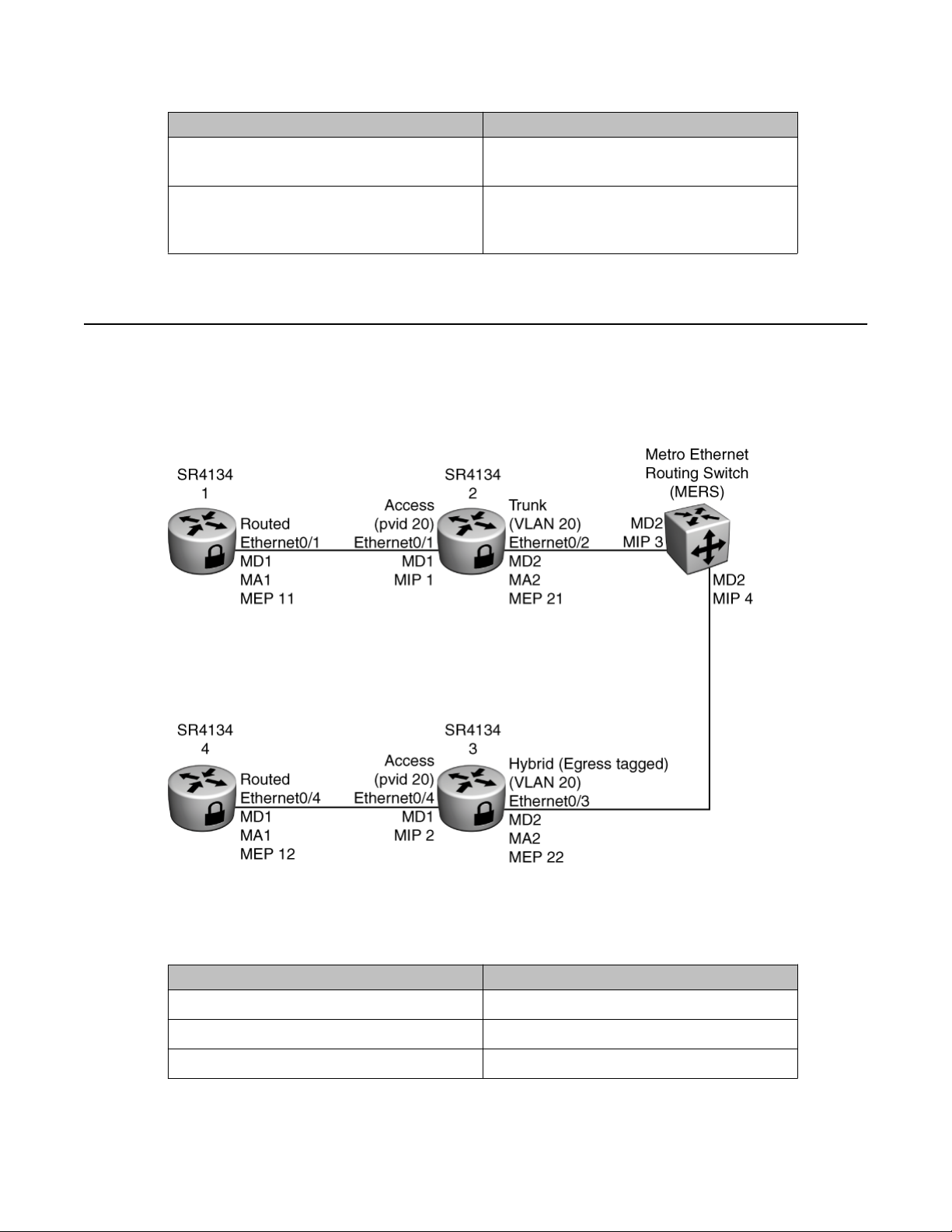
Example of configuring Ethernet Connectivity Fault Management
Variable Value
terminates. Enter a value from 1 to 255. The
default value is 64.
[priority <priority_indicator>] The user priority field in the VLAN tag. The
default priority indicator is 7. The range is 0
to 7.
Example of configuring Ethernet Connectivity Fault
Management
The following figure shows the network setup for the example Ethernet CFM configuration.
Figure 12: Example network for Ethernet CFM
Table 24: Ethernet CFM MAC addresses
Interface MAC address
SR2330/4134 1 Ethernet0/1 00:01:01:01:01:01
SR2330/4134 2 Ethernet0/1 00:01:02:01:01:01
SR2330/4134 2 Ethernet0/2 00:01:02:01:01:02
Configuration — Layer 2 Ethernet July 2013 67
Page 68

Ethernet Connectivity Fault Management configuration
Interface MAC address
SR2330/4134 3 Ethernet0/3 00:01:03:01:01:03
SR2330/4134 3 Ethernet0/4 00:01:03:01:01:04
SR2330/4134 4 Ethernet0/4 00:01:04:01:01:04
Procedure steps
1. To configure SR2330/4134 1, enter:
configure terminal
oam
cfm
ethtype 88e6
linktrace 150
md MD1
level 5
ma MA1
mep 11 0/1 mep-state enable
rmep 12
pop
2. To configure SR2330/4134 4, enter:
configure terminal
oam
cfm
md MD1
level 5
ma MA1
mep 12 0/4 mep-state enable
rmep 11
pop
3. To configure SR2330/4134 2, enter:
configure terminal
oam
cfm
md MD1
level 5
mip 1
interface 0/1
vlan 20
exit
exit
md MD2
level 3
ma MA2
mep 21 0/2 mep-state enable
vlan 20
cc auto-detect-rmeps enable
pop
4. To configure SR2330/4134 3, enter:
configure terminal
oam
cfm
md MD1
level 5
mip 2
interface 0/4
68 Configuration — Layer 2 Ethernet July 2013
Comments? [email protected]
Page 69

Example of configuring Ethernet Connectivity Fault Management
vlan 20
exit
exit
md MD2
level 3
ma MA2
mep 22 0/3 mep-state enable
vlan 20
cc auto-detect-rmeps enable
pop
5. To test the connection from MEP 11 to remote MEP 12, enter:
SR4134 1/test/oam/cfm MD1 MA1 11# lbmmep rmep-id 12
The router returns the following:
Loopback test: MEP ID: 11, RMEP ID: 12, RMEP MAC:
00:01:04:01:01:04,
First Transaction ID Tx: 9173
No.of LBMs sent : 1
No.of Valid LBRs received: 1
LBRs rx in-order: 1
LBRs rx out-of-order: 0
LBRs rx with DataTLV error: 0
No. of packets lost : 0
Loss rate: 0 %
No.of Unexpected LBRs received: 0
6. To perform a linktrace test between MEP 11 and remote MEP 12, enter:
SR4134 1/test/oam/cfm MD1 MA1 11# ltmmep rmep-id 12
The router returns the following:
Linktrace Test Started, Session ID: 1
Use 'show cfm linktrace-cache' command to display results
7. To display results for the linktrace test between MEP 11 and remote MEP 12, enter:
SR4134 1/test/oam/cfm MD1 MA1 11# show cfm linktrace-cache session 1
Link trace session 1: MEP ID: 11, RMEP ID: 12, RMEP MAC:
00:01:02:01:01:01, Transaction ID Tx: 9174
Reply #1
-------------
Errors in LTR: No
Remote MAC addr: 00:01:02:01:01:01
LTM Forwarded? Yes
Configuration — Layer 2 Ethernet July 2013 69
Page 70

Ethernet Connectivity Fault Management configuration
Terminal MP? No
Transaction ID: 9174
Last Egress ID: 00:01:01:01:01:01
Next Egress ID: 00:01:02:01:01:01
Reply TTL: 63
Summary:
-----------------------------------------------
Reply #Remote MACErrors?Forward?TTL
-----------------------------------------------
100:01:02:01:01:01NoY63
-----------------------------------------------
Reply #2 -------------
Errors in LTR: No
Remote MAC addr: 00:01:03:01:01:04
LTM Forwarded? Yes
Terminal MP? No
Transaction ID: 9174
Last Egress ID: 00:01:02:01:01:01
Next Egress ID: 00:01:03:01:01:04
Reply TTL: 62
Summary:
-----------------------------------------------
Reply #Remote MACErrors?Forward?TTL
-----------------------------------------------
200:01:03:01:01:04NoY62
-----------------------------------------------
Reply #3
-------------
Errors in LTR: No
Remote MAC addr: 00:01:04:01:01:04
LTM Forwarded? No
70 Configuration — Layer 2 Ethernet July 2013
Comments? [email protected]
Page 71
Displaying Ethernet CFM information
Terminal MP? Yes
Transaction ID: 9174
Last Egress ID: 00:01:03:01:01:04
Next Egress ID:
Reply TTL: 61
Summary:
-----------------------------------------------
Reply #Remote MACErrors?Forward?TTL
-----------------------------------------------
300:01:04:01:01:04NoY61
-----------------------------------------------
Displaying Ethernet CFM information
Use the procedures in this section to view information related to your CFM configuration.
Displaying information related to Maintenance Domains
Use the commands in this section to view information related to the configuration of MDs.
Procedure steps
1. To display summary information for all MDs, enter:
show cfm mds
2. To display detailed information for a specific MD, enter:
show cfm md <WORD>
Table 25: Variable definitions
Variable
<WORD> The short name of the MD (up to eight
characters). For example MD1.
Value
Configuration — Layer 2 Ethernet July 2013 71
Page 72

Ethernet Connectivity Fault Management configuration
Displaying information related to Maintenance Associations
Use the commands in this section to view information related to the configuration of MAs.
Procedure steps
1. To display summary information for all MAs within an MD, enter:
show cfm mas md <WORD>
2. To display detailed information for a specific MA, enter:
show cfm ma <WORD> [md-name <WORD>]
Table 26: Variable definitions
Variable Value
ma <WORD> The short name of the MA (up to eight
characters). For example, MA1.
md-name <WORD> The short name of the MD (up to eight
characters). For example, MD1.
Displaying information related to MEPs and MIPs
Use the commands in this section to view information related to the configuration of MEPs,
remote MEPs, and MIPs.
Procedure steps
1. To display summary information for all MEPs (including remote MEPs) configured
within a specific MA and MD, enter:
show cfm meps ma <WORD> md <WORD>
2. To display summary information for a remote MEP configured within the specified
MA (and MD), enter:
show cfm rmep <rmep id> ma <WORD> md <WORD>
3. To display detailed information for a specific MEP, enter:
show cfm mep <mep id> [ma <WORD>] [md <WORD>]
4. To display summary information for all MIPs configured in the Secure Router
2330/4134, enter:
show cfm mips [md <WORD>]
5. To display detailed information for a specific MIP, enter:
show cfm mip <mip id> [md <WORD>]
72 Configuration — Layer 2 Ethernet July 2013
Comments? [email protected]
Page 73

Displaying Ethernet CFM information
Table 27: Variable definitions
Variable Value
ma <WORD> The short name of the MA (up to eight
characters). For example MA1.
md <WORD> The short name of the MD (up to eight
characters). For example MD1.
<mep id> The numerical identifier for the MEP. Values
are in the range from 1 to 8191.
<mip id> The numerical identifier for the MIP. Values
are in the range from 1 to 8191.
<rmep id> The numerical identifier for the remote MEP.
Values are in the range from 1 to 8191.
Displaying information related to continuity checks
Use the commands in this section to view information related to CC configuration.
Procedure steps
1. To display information about CC configuration, enter:
show cfm cc-configs
2. To display information about CC configuration for a specific MA within a specific
MD, enter:
show cfm cc-configs ma <WORD> md <WORD>
Table 28: Variable definitions
Variable
ma <WORD> The short name of the MA (up to eight
characters). For example MA1.
md <WORD> The short name of the MD (up to eight
characters). For example MD1.
Displaying information related to CFM errors
Value
Use the commands in this section to view information related to CC errors.
Configuration — Layer 2 Ethernet July 2013 73
Page 74

Ethernet Connectivity Fault Management configuration
Procedure steps
To display information about CC errors logged to the Secure Router 2330/4134 since
the reset or clear of a specific MEP, enter:
show cfm errors mep <mep id> md <WORD> ma <WORD>
Table 29: Variable definitions
Variable Value
<mep id> The numerical identifier for the MEP. Values
are in the range from 1 to 8191.
md <WORD> The short name of the MD (up to eight
characters). For example MD1.
ma <WORD> The short name of the MA (up to eight
characters). For example MA1.
Displaying information related to CFM stats
Use the commands in this section to view information related to CFM statistics.
Procedure steps
1. To display stats for an MEP logged to the Secure Router 2330/4134 since a reset
or clear, enter:
show cfm mep-stats [mep <mep id> md <WORD> ma <WORD>]
2. To display stats for an MIP logged to the Secure Router 2330/4134 since a reset or
clear, enter:
show cfm mip-stats [md <WORD> mip <mip id>]
Table 30: Variable definitions
Variable
<mep id> The numerical identifier for the MEP. Values
are in the range from 1 to 8191.
<mip id> The numerical identifier for the MIP. Values
are in the range from 1 to 8191.
md <WORD> The short name of the MD (up to eight
characters). For example MD1.
ma <WORD> The short name of the MA (up to eight
characters). For example MA1.
Value
74 Configuration — Layer 2 Ethernet July 2013
Comments? [email protected]
Page 75

Displaying Ethernet CFM information
Displaying information related to path trace cache entries
Use the commands in this section to view information related to path trace cache entries.
Procedure steps
To display path trace cache entries logged to the Secure Router 2330/4134 since a
reset or clear, enter:
show cfm linktrace-cache [session <session id>] [mep <mep id>]
[rmep-id <rmep id>] [ma <WORD>] [md <WORD>] [mac-addr <mac
addr>]
Table 31: Variable definitions
Variable Value
<mep id> The numerical identifier for the MEP. Values
are in the range from 1 to 8191.
<rmep id> The numerical identifier for the remote MEP.
Values are in the range from 1 to 8191.
md <WORD> The short name of the MD (up to eight
characters). For example MD1.
ma <WORD> The short name of the MA (up to eight
characters). For example MA1.
<mac addr> The MAC address of the remote host. Enter
a MAC address in the form
aa:bb:cc:dd:ee:ff.
<session id> The linktrace test session ID. Values are in
the range 1 to 4294967295.
Displaying CFM global configuration
Use the commands in this section to view information related to CFM global configuration.
Procedure steps
To display CFM global configuration, enter:
Configuration — Layer 2 Ethernet July 2013 75
Page 76

Ethernet Connectivity Fault Management configuration
show cfm global-config
Clearing Ethernet CFM information
Use the procedure in this section to clear errors or stats related to CFM, or to clear the Linktrace
cache.
Procedure steps
1. To clear CCM errors logged to the Secure Router 2330/4134, enter:
clear cfm errors [md <WORD>] [ma <WORD>] [mep <mep id>]
2. To clear CFM MEP stats logged to the Secure Router 2330/4134, enter:
clear cfm mep-stats [mep <mep id> md <WORD> ma <WORD>]
3. To clear CFM MIP stats logged to the Secure Router 2330/4134, enter:
clear cfm mip-stats [md <WORD> mip <mip id>]
4. To clear the path trace cache entries logged to the Secure Router 2330/4134, enter:
clear cfm linktrace-cache [session <session id>] [mep <mep
id>] [rmep-id <rmep id>] [ma <WORD>] [md <WORD>] [mac-addr
<mac addr>]
Table 32: Variable definitions
Variable
mep <mep id> The numerical identifier for the local MEP.
Values are in the range from 1 to 8191.
mip <mip id> The numerical identifier for the MIP. Values
are in the range from 1 to 8191.
rmep <rmep id> The numerical identifier for the remote MEP.
Values are in the range from 1 to 8191.
ma <WORD> The short name of the MA (up to eight
characters). For example MA1.
md <WORD> The short name of the MD (up to eight
characters). For example MD1.
mac-addr <mac addr> The MAC address of the remote host. Enter
a MAC address in the form
aa:bb:cc:dd:ee:ff.
Value
session <session id> The linktrace test session ID. Values are in
the range 1 to 4294967295.
76 Configuration — Layer 2 Ethernet July 2013
Comments? [email protected]
Page 77

Chapter 8: Secure Router 2330/4134
Ethernet interfaces
configuration
Use the procedures in this section for your basic Ethernet interface configuration.
Configuring Maximum Transmission Unit size
Use the procedure in this section to configure the MTU size for an Ethernet interface.
Important:
The Avaya Secure Router 2330/4134 management Ethernet interface (FE 0/0) on the rear
panel does not support jumbo frames. Therefore, the management port Maximum
Transmission Unit (MTU) can be configured with a value in the range of 64 to 1500 bytes.
Important:
The Secure Router 2330/4134 management Ethernet interface (FE 0/0) is automatically
disabled when you install a Digital Signal Processor (DSP).
Procedure steps
1. To access configuration mode, enter:
configure terminal
2. To select an interface, enter:
interface ethernet <slot/port>
3. To configure the MTU size, enter:
mtu <size>
Table 33: Variable definitions
Variable
<size> Specifies the MTU size. Valid values are 64
to 9216. The default value is 1500.
Value
Configuration — Layer 2 Ethernet July 2013 77
Page 78

Secure Router 2330/4134 Ethernet interfaces configuration
Variable Value
<slot/port> Specifies the slot and port numbers that
Configuring jumbo frames
The Secure Router 2330/4134 supports jumbo frames.
Important:
The Secure Router 2330/4134 management Ethernet interface (FE 0/0) on the rear panel
does not support jumbo frames. Therefore, the management port Maximum Transmission
Unit (MTU) can be configured with a value in the range of 64 to 1500 bytes.
Use the procedure in this section to configure the Secure Router 2330/4134 system settings
to support jumbo frames.
identify the port for configuration. For
example, 6/1.
Procedure steps
1. To access configuration mode, enter:
configure terminal
2. To configure the system settings to support jumbo frames, enter:
system jumbo-mtu-limit <value>
3. Reboot the system.
Table 34: Variable definitions
Variable
<value> Valid values for the jumbo MTU limit are 1500
and 9216 bytes. The default value is 1500
bytes.
Adding comments to an interface
Use the procedures in this section to add comments to an interface.
Value
78 Configuration — Layer 2 Ethernet July 2013
Comments? [email protected]
Page 79

Adding comments to an interface
Adding comments at the beginning of a configuration file
Use the procedure in this section to add comments at the beginning of the Ethernet area of a
configuration file.
Procedure steps
1. To access configuration mode, enter:
configure terminal
2. To select an interface, enter:
interface ethernet <slot/port>
3. To enter a comment:
REM <string>
Table 35: Variable definitions
Variable Value
<string> Specifies the comments. The string length
for comments is 80 characters. You must
enclose comments in quotation marks. For
example, REM "Configured on July
30".
<slot/port> Specifies the slot and port numbers that
identify the port for configuration. For
example, 6/1.
Adding comments at the end of a configuration file
Use the procedures in this section to add comments to an interface. The comments appear at
the end of the Ethernet area of a configuration file.
Procedure steps
1. To access configuration mode, enter:
configure terminal
2. To select an interface, enter:
interface ethernet <slot/port>
3. To enter a comment:
REM_ <string>
Configuration — Layer 2 Ethernet July 2013 79
Page 80

Secure Router 2330/4134 Ethernet interfaces configuration
Table 36: Variable definitions
Variable Value
<string> Specifies the comments. The string length
for comments is 80 characters. You must
enclose comments in quotation marks. For
example, REM_ "Configured on
July 30".
<slot/port> Specifies the slot and port numbers that
identify the port for configuration. For
example, 6/1.
Adding a description to an interface
Use the procedure in this section to configure a description for an Ethernet interface. With
Release 10.2 and later, the description string can be up to 76 characters.
Procedure steps
1. To access configuration mode, enter:
configure terminal
2. To select an interface, enter:
interface ethernet <slot/port>
3. To configure a description, enter:
description <string>
Table 37: Variable definitions
Variable
<string> Specifies the description. The string length
for a description is 76 characters. You must
enclose the description in quotation marks.
For example, description "Main
Value
LAN".
<slot/port> Specifies the slot and port numbers that
identify the port for configuration. For
example, 6/1.
80 Configuration — Layer 2 Ethernet July 2013
Comments? [email protected]
Page 81

Configuring the speed of an interface
Use the procedure in this section to configure the speed of an Ethernet interface.
Procedure steps
1. To access configuration mode, enter:
configure terminal
2. To select an interface, enter:
interface ethernet <slot/port>
3. To configure the speed, enter:
speed {10|100|1000|auto} mode {half_duplex|full_duplex}
Table 38: Variable definitions
Configuring the speed of an interface
Variable Value
{10 | 100 | 1000 | auto} Specifies the speed of the port. The default
value is auto.
{half_duplex | full_duplex} Specifies the operating mode for the port.
The default value is half_duplex.
<slot/port> Specifies the slot and port numbers that
identify the port for configuration. For
example, 6/1.
Configuration — Layer 2 Ethernet July 2013 81
Page 82

Secure Router 2330/4134 Ethernet interfaces configuration
82 Configuration — Layer 2 Ethernet July 2013
Comments? [email protected]
Page 83

Chapter 9: Layer 2 configuration
You configure Layer 2 (data link layer) features to allow traffic to pass between adjacent network nodes
in a WAN, or between devices on the same LAN segment.
With Release 10.2 and later, you can specify a range of Ethernet ports to configure at the same time. To
do so, you must use the interface range ethernet command.
Prerequisites to Layer 2 configuration
• The Avaya Secure Router 2330/4134 must be securely installed in an equipment rack,
and properly grounded.
• You must have commissioned your Secure Router 2330/4134 so it is ready for software
feature configuration.
• You can configure Layer 2 features (with the exception of port mirroring and LACP) on
WAN interfaces that are configured with Point-to-Point Protocol (PPP) or Frame Relay
(FR) encapsulation. Ensure you have planned the relationship between WAN interfaces
and Layer 2 features for your network. For example, if you plan to configure VLAN stacking
on WAN bundles, ensure you have configured the required bundles.
Layer 2 configuration procedures
This task flow shows you the sequence of procedures you perform to configure Layer 2 features
on the Secure Router 2330/4134.
Configuration — Layer 2 Ethernet July 2013 83
Page 84
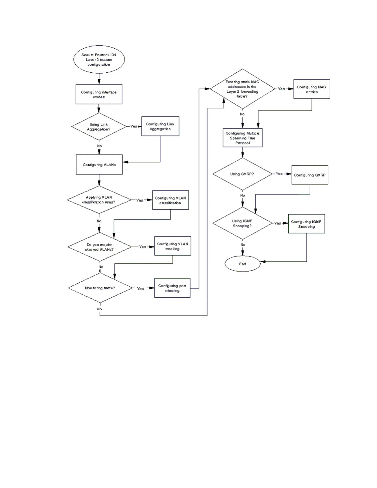
Layer 2 configuration
Figure 13: Layer 2 configuration procedures
84 Configuration — Layer 2 Ethernet July 2013
Comments? [email protected]
Page 85

Chapter 10: Interface mode configuration
You can configure a port on an Avaya Secure Router 2330/4134 as an access port, a trunk port, or a
hybrid port.
You can enable Layer 2 switching on all Ethernet and WAN interfaces. The Secure Router 2330/4134
supports all Layer 2 switching features on WAN interfaces that are configured with PPP or FR
encapsulation. This section describes the supported interface modes and how to configure each mode
on LAN and WAN interfaces.
Configuring trunking on Ethernet interfaces
Trunk links are required to pass VLAN information between devices. You can configure a trunk
port to be a member of all the VLANs that exist on the device. That port then carries traffic for
all the VLANs between the devices. To distinguish between the traffic flows, a trunk port must
mark the frames with special tags as they pass between the devices. You must enable trunking
on both sides of a link. If two devices are connected together, for example, you must configure
both device ports for trunking.
Enabling trunking on an Ethernet port
Use the procedure in this section to enable trunking between the devices.
Procedure steps
1. To access configuration mode, enter:
configure terminal
2. To select an Ethernet interface, enter:
interface [range] ethernet <slot/port>
3. To configure the port as a Layer 2 interface, enter:
switchport
4. To configure the interface as a trunk port, enter:
switchport mode trunk
Configuration — Layer 2 Ethernet July 2013 85
Page 86

Interface mode configuration
Specifying VLANs to trunk
You can configure a trunk link to carry all the VLANs that exist on the device. You can also
selectively add VLANs to and remove VLANs from a trunk link. Use the procedures in this
section to specify the VLANs to add or remove from a trunk link.
Adding all VLANs to a trunk link
Use the procedure in this section to add all VLANs to a trunk link.
Procedure steps
1. To access configuration mode, enter:
configure terminal
2. To select an interface, enter:
interface [range] ethernet <slot/port>
3. To add all VLANs to the selected trunk link, enter: switchport trunk allowed
vlan all
Removing all VLANs from a trunk link
Use the procedure in this section to remove all VLANs from a trunk link.
Procedure steps
1. To access configuration mode, enter:
configure terminal
2. To select an interface, enter:
interface [range] ethernet <slot/port>
3. To remove all VLANs from the selected trunk link, enter:
switchport trunk remove vlan all
Adding a specified VLAN to a trunk link
Use the procedure in this section to selectively add VLANs to a trunk link.
Procedure steps
1. To access configuration mode, enter:
86 Configuration — Layer 2 Ethernet July 2013
Comments? [email protected]
Page 87

configure terminal
2. To select an interface, enter:
interface [range] ethernet <slot/port>
3. To add a specific VLAN to the selected trunk link, enter:
switchport trunk allowed vlan <vid>
Note:
To add multiple VLANs to the selected trunk link, enter each VLAN ID separated
by a comma. For example, switchport trunk allowed vlan 2,3
Removing a specified VLAN from a trunk link
Use the procedure in this section to selectively remove VLANs from a trunk link.
Procedure steps
1. To access configuration mode, enter:
Configuring trunking on Ethernet interfaces
configure terminal
2. To select an interface, enter:
interface [range] ethernet <slot/port>
3. To remove a specific VLAN from the selected trunk link, enter:
switchport trunk remove vlan <vid>
Disabling trunking
Use the procedure in this section to disable trunking on an interface.
Procedure steps
1. To access configuration mode, enter:
configure terminal
2. To select an interface, enter:
interface [range] ethernet <slot/port>
3. To disable trunking on the interface, enter:
no switchport
Configuration — Layer 2 Ethernet July 2013 87
Page 88

Interface mode configuration
Verifying trunks
Use the procedure in this section to verify the successful configuration of trunks. With Release
10.2 and later, the show interface ethernet command displays the highest supported
capability for each interface: FE for Fast Ethernet and GE for Gigabit Ethernet.
Procedure steps
1. To view information related to the interface mode, enter:
show bridge port
2. To view information related to the operation of the trunk port, enter:
show interface ethernet <slot/port>
Example of configuring trunking on a chassis Ethernet interface
Procedure steps
1. To access configuration mode, enter:
configure terminal
2. To select the chassis Ethernet interface (in this example, interface 0/1), enter:
interface ethernet 0/1
3. To configure the interface as a Layer 2 interface, enter:
switchport
4. To configure the interface as a trunk, enter:
switchport mode trunk
Configuring trunking on a WAN interface
Use the procedures in this section to configure trunking on a WAN interface. For detailed
information about how to configure WAN interfaces, see Avaya Secure Router 2330/4134
Configuration — WAN interfaces (NN47263-500).
For an example network scenario that shows the use of trunking, see
VLAN stacking on page 128.
Example of configuring
88 Configuration — Layer 2 Ethernet July 2013
Comments? [email protected]
Page 89

Enabling trunking on WAN interfaces
You can configure trunking on WAN interfaces that are configured with PPP or FR
encapsulation.
Procedure steps
1. To access configuration mode, enter:
configure terminal
2. To select an interface, enter:
interface bundle <bundle-name>
3. To link the interface to the bundle, enter:
link <type> <slot/port>
4. To configure the encapsulation for the bundle, enter:
encapsulation {ppp|fr}
Configuring trunking on a WAN interface
5. To configure the interface as a Layer 2 interface, enter:
switchport
6. To configure the interface as a trunk, enter:
switchport mode trunk
Table 39: Variable definitions
Variable
<bundle-name> Specifies the name of the bundle. For
example, T1IF.
{ppp | fr} Specifies the encapsulation. You can
configure trunking only on WAN interfaces
that are configured with PPP or FR
encapsulation.
<slot/port> Specifies the slot and port numbers that
identify the port on which you enable a trunk.
For example, 7/1.
<type> Specifies the type of WAN interface. For
example, t1. For detailed information on
WAN interfaces that support PPP or FR
encapsulation, see Avaya Secure Router
2330/4134 Configuration — WAN
interfaces (NN47263-500).
Value
Configuration — Layer 2 Ethernet July 2013 89
Page 90

Interface mode configuration
Adding all VLANs to a trunk link
Use the procedure in this section to add all VLANs to a trunk link.
Procedure steps
1. To access configuration mode, enter:
configure terminal
2. To select a WAN interface, enter:
interface bundle <bundle-name>
3. To add all VLANs to the selected trunk link, enter:
switchport trunk allowed vlan all
Removing all VLANs from a trunk link
Use the procedure in this section to remove all VLANs from a trunk link.
Procedure steps
1. To access configuration mode, enter:
configure terminal
2. To select a WAN interface, enter:
interface bundle <bundle-name>
3. To remove all VLANs from the selected trunk link, enter:
switchport trunk remove vlan all
Adding a specified VLAN to a trunk link
Use the procedure in this section to selectively add VLANs to a trunk link.
Procedure steps
1. To access configuration mode, enter:
configure terminal
2. To select a WAN interface, enter:
interface bundle <bundle-name>
3. To add a specific VLAN to the selected interface, enter:
90 Configuration — Layer 2 Ethernet July 2013
Comments? [email protected]
Page 91

Configuring trunking on a WAN interface
switchport trunk allowed vlan <vid>
Removing a specified VLAN from a trunk link
Use the procedure in this section to selectively remove VLANs from a trunk link.
Procedure steps
1. To access configuration mode, enter:
configure terminal
2. To select a WAN interface, enter:
interface bundle <bundle-name>
3. To remove a specific VLAN from the selected trunk link, enter:
switchport trunk remove vlan <vid>
Disabling trunking
Use the procedure in this section to disable trunking on an interface.
Procedure steps
1. To access configuration mode, enter:
configure terminal
2. To select a WAN interface, enter:
interface bundle <bundle-name>
3. To disable trunking on the interface, enter:
no switchport
Verifying trunks
Use the procedure in this section to verify the successful configuration of trunks on WAN
interfaces.
Procedure steps
1. To view information related to the interface mode, enter:
show bridge port
2. To view information related to the operation of the trunk port, enter:
Configuration — Layer 2 Ethernet July 2013 91
Page 92

Interface mode configuration
show interface bundle <bundle-name>
Example of configuring trunking on a WAN interface
Procedure steps
1. To access configuration mode, enter:
configure terminal
2. To select a bundle (in this example, the bundle identified as BRI1IF), enter:
interface bundle BRI1IF
3. To link the bundle to an interface (in this example, the interface is port 1 of the
module in slot 3), enter:
link t1 3/1
4. To configure the encapsulation, enter:
encapsulation ppp
5. To configure the interface as a Layer 2 interface, enter:
switchport
6. To configure the interface as a trunk interface, enter:
switchport mode trunk
Configuring a hybrid link on an Ethernet interface
A hybrid link is a LAN segment that contains both VLAN-aware and VLAN-unaware devices.
Consequently, a hybrid link can carry both VLAN tagged frames and other (untagged or prioritytagged) frames.
Use the procedure in this section to enable a hybrid link between devices.
Procedure steps
1. To access configuration mode, enter:
configure terminal
2. To select an Ethernet interface, enter:
interface [range] ethernet <slot/port>
3. To configure the interface as a Layer 2 interface, enter:
switchport
4. To configure the interface as a hybrid port, enter:
92 Configuration — Layer 2 Ethernet July 2013
Comments? [email protected]
Page 93
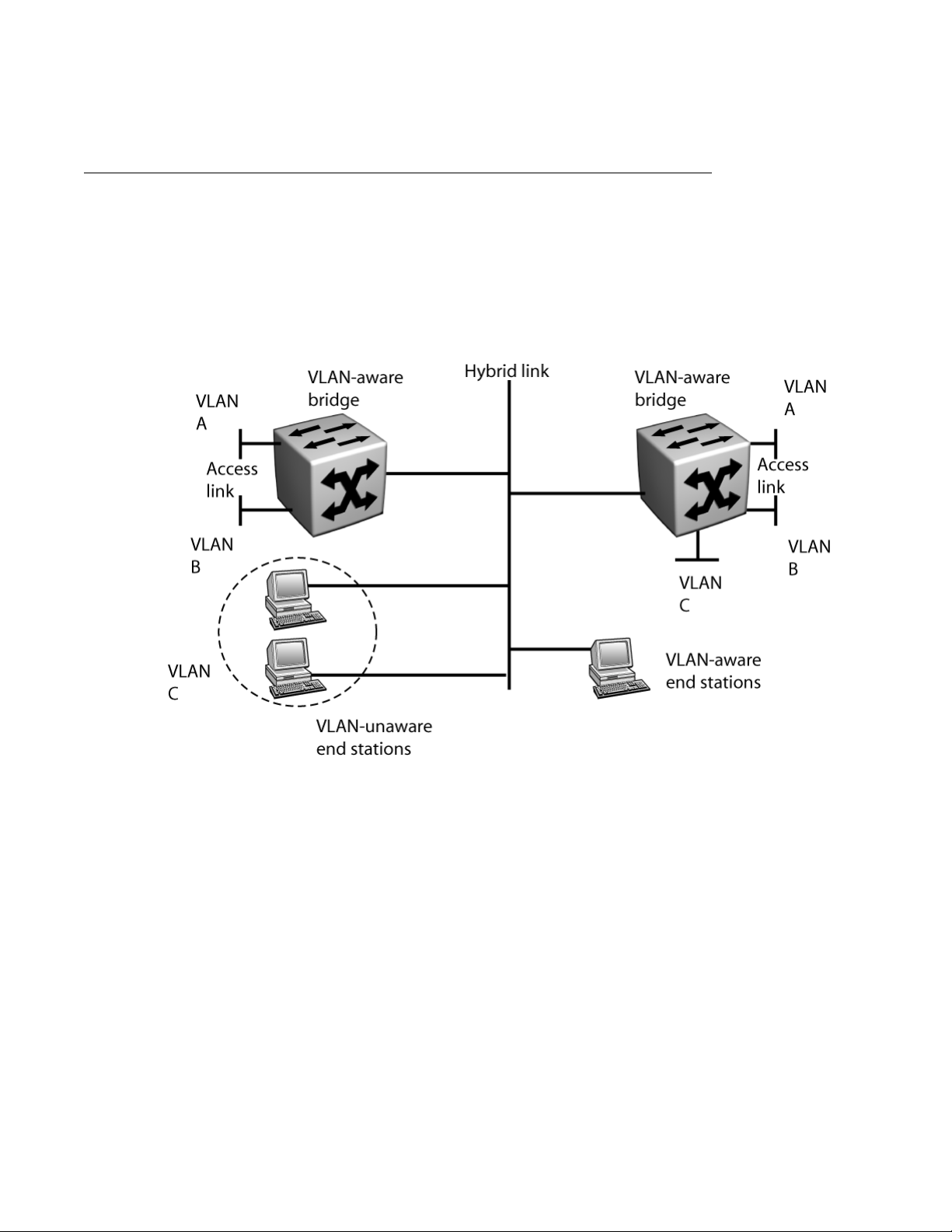
switchport mode hybrid
Associating VLANs with hybrid links
When configuring hybrid links, ensure that all frames transmitted by a bridge on a hybrid link
are tagged in the same way on that link. The frames must be either all tagged, or all tagged
and carrying the same VLAN ID.
A bridge can transmit a mix of VLAN-tagged frames and untagged frames, but the frames must
be for different VLANs. In the following figure, all the frames for VLAN A and VLAN B are tagged
on the hybrid link. All frames for VLAN C on the hybrid link are untagged.
Configuring a hybrid link on an Ethernet interface
Figure 14: Hybrid link network scenario
Adding all VLANs to a hybrid link
Use the procedure in this section to add all VLANs to a hybrid link.
Procedure steps
1. To access configuration mode, enter:
configure terminal
2. To select an interface, enter:
Configuration — Layer 2 Ethernet July 2013 93
Page 94

Interface mode configuration
interface [range] ethernet <slot/port>
3. To add all VLANs to the selected hybrid link, enter:
switchport hybrid allowed vlan all egress {tagged|untagged}
Removing all VLANs from a hybrid link
Use the procedure in this section to remove all VLANs from a hybrid link.
Procedure steps
1. To access configuration mode, enter:
configure terminal
2. To select an interface, enter:
interface [range] ethernet <slot/port>
3. To remove all VLANs from the selected hybrid link, enter:
switchport hybrid remove vlan all egress {tagged|untagged}
Adding a specified VLAN to a hybrid link
Use the procedure in this section to selectively add VLANs to a hybrid link.
Procedure steps
1. To access configuration mode, enter:
configure terminal
2. To select an interface, enter:
interface [range] ethernet <slot/port>
3. To add a specific VLAN to the selected hybrid link, enter:
switchport hybrid allowed vlan <vid> egress {tagged|untagged}
Removing a specified VLAN from a link
Use the procedure in this section to selectively remove VLANs from a hybrid link.
Procedure steps
1. To access configuration mode, enter:
configure terminal
2. To select an interface, enter:
94 Configuration — Layer 2 Ethernet July 2013
Comments? [email protected]
Page 95

interface [range] ethernet <slot/port>
3. To remove a specific VLAN from the selected hybrid link, enter:
switchport hybrid remove vlan <vid> egress {tagged|untagged}
Disabling a hybrid link
Use the procedure in this section to disable a hybrid link.
Procedure steps
1. To access configuration mode, enter:
configure terminal
2. To select an interface, enter:
interface [range] ethernet <slot/port>
3. To disable the hybrid link on the interface, enter:
no switchport
Configuring a hybrid link on an Ethernet interface
Verifying a hybrid link
Use the procedure in this section to verify the successful configuration of a hybrid link. With
Release 10.2 and later, the show interface ethernet command displays the highest
supported capability for each interface: FE for Fast Ethernet and GE for Gigabit Ethernet.
Procedure steps
1. To view information related to the interface mode, enter:
show bridge port
2. To view information related to the operation of the hybrid interface, enter:
show interface ethernet <slot/port>
Example of configuring a hybrid link on a chassis Ethernet interface
Procedure steps
1. To access configuration mode, enter:
configure terminal
2. To select an Ethernet interface (in this example, Ethernet interface 0/1), enter:
interface ethernet 0/1
Configuration — Layer 2 Ethernet July 2013 95
Page 96

Interface mode configuration
3. To configure the interface as a Layer 2 interface, enter:
switchport
4. To configure the interface as a hybrid link, enter:
switchport mode hybrid
Configuring a hybrid link on a WAN interface
Use the procedures in this section to configure and enable a hybrid link on a WAN interface.
Enabling a hybrid link on a WAN interface
Use the procedure in this section to enable a hybrid link between devices.
Procedure steps
1. To access configuration mode, enter:
configure terminal
2. To select an interface, enter:
interface bundle <bundle-name>
3. To link the interface to the bundle, enter:
link <type> <slot/port>
4. To configure the encapsulation for the bundle, enter:
encapsulation {ppp|fr}
5. To configure the interface as a Layer 2 interface, enter:
switchport
6. To configure the interface as a hybrid port, enter:
switchport mode hybrid
Table 40: Variable definitions
Variable
<bundle-name> Specifies the name of the bundle. For
example, T1IF.
Value
{ppp | fr} Specifies the encapsulation. You can
configure a hybrid link only on WAN
interfaces that are configured with PPP or FR
encapsulation.
96 Configuration — Layer 2 Ethernet July 2013
Comments? [email protected]
Page 97
Variable Value
<slot/port> Specifies the slot and port numbers that
<type> Specifies the type of WAN interface. For
Adding all VLANs to a hybrid link
Use the procedure in this section to add all VLANs to a hybrid link.
Procedure steps
1. To access configuration mode, enter:
Configuring a hybrid link on a WAN interface
identify the port on which you enable the
hybrid link. For example, 7/1.
example, t1. For detailed information on
WAN interfaces that support PPP or FR
encapsulation, see Avaya Secure Router
2330/4134 Configuration — WAN
interfaces (NN47263-500).
configure terminal
2. To select an interface, enter:
interface bundle <bundle-name>
3. To add all VLANs to the selected hybrid link, enter:
switchport hybrid allowed vlan all egress {tagged|untagged}
Removing all VLANs from a hybrid link
Use the procedure in this section to remove all VLANs from a hybrid link.
Procedure steps
1. To access configuration mode, enter:
configure terminal
2. To select an interface, enter:
interface bundle <bundle-name>
3. To remove all VLANs from the selected hybrid link, enter:
switchport hybrid remove vlan all egress {tagged|untagged}
Configuration — Layer 2 Ethernet July 2013 97
Page 98

Interface mode configuration
Adding a specified VLAN to a hybrid link
Use the procedure in this section to selectively add VLANs to a hybrid link.
Procedure steps
1. To access configuration mode, enter:
configure terminal
2. To select an interface, enter:
interface bundle <bundle-name>
3. To add a specific VLAN to the selected hybrid link, enter:
switchport hybrid allowed vlan <vid> egress {tagged|untagged}
Removing a specified VLAN from a link
Use the procedure in this section to selectively remove VLANs from a hybrid link.
Procedure steps
1. To access configuration mode, enter:
configure terminal
2. To select an interface, enter:
interface bundle <bundle-name>
3. To remove a specific VLAN from the selected hybrid link, enter:
switchport hybrid remove vlan <vid> egress {tagged|untagged}
Disabling a hybrid link
Use the procedure in this section to disable a hybrid link.
Procedure steps
1. To access configuration mode, enter:
configure terminal
2. To select an interface, enter:
interface bundle <bundle-name>
3. To disable the hybrid link on the interface, enter:
98 Configuration — Layer 2 Ethernet July 2013
Comments? [email protected]
Page 99

Configuring an access port on an Ethernet interface
no switchport
Verifying a hybrid link
Use the procedure in this section to verify the successful configuration of a hybrid link.
Procedure steps
1. To view information related to the interface mode, enter:
show bridge port
2. To view information related to the operation of the hybrid interface, enter:
show interface bundle <bundle-name>
Example of configuring a hybrid link on a WAN interface
Procedure steps
1. To access configuration mode, enter:
configure terminal
2. To select a bundle (in this example, the bundle identified as BRI1IF), enter:
interface bundle BRI1IF
3. To link the bundle to an interface (in this example, the interface is port 1 of the
module in slot 3), enter:
link BRI 3/1
4. To configure the encapsulation, enter:
encapsulation ppp
5. To configure the interface as a Layer to interface, enter:
switchport
6. To configure the interface as a hybrid link, enter:
switchport mode hybrid
Configuring an access port on an Ethernet interface
Access ports belong to a single VLAN and do not provide any identifying marks on the frames
that are passed between devices. Access ports carry traffic that comes only from the VLAN
assigned to the port.
Configuration — Layer 2 Ethernet July 2013 99
Page 100

Interface mode configuration
For an example network scenario that shows the use of trunking, see Example of configuring
VLAN stacking on page 128.
Enabling an access link on an Ethernet port
Use the procedure in this section to enable an access link between the devices.
Procedure steps
1. To access configuration mode, enter:
configure terminal
2. To select an interface, enter:
interface [range] ethernet <slot/port>
3. To configure the interface as an access port, enter:
switchport
Associating VLANs with access links
There can be only one VLAN assigned to an access port. VLAN ID 1 is the default VLAN
assigned to each port. Use the procedures in this section to specify the VLANs to add to or
remove from an access link.
Changing the VLAN on an access port
Use the procedure in this section to change the VLAN assigned to an access link.
Procedure steps
1. To access configuration mode, enter:
configure terminal
2. To select an interface, enter:
interface [range] ethernet <slot/port>
3. To assign a VLAN to the selected access port, enter:
switchport pvid <vid>
Disabling an access port
Use the procedure in this section to disable an access port.
100 Configuration — Layer 2 Ethernet July 2013
Comments? [email protected]
 Loading...