

Page 1

Compact Contact Center
Installation & Maintenance
40DHB0002USBG Issue 1 (11/14/2001)
Page 2

Contents
Contents
Introduction............................................................................................................................................... 3
General .................................................................................................................................................. 3
Overview ................................................................................................................................................ 4
System Specification.............................................................................................................................. 5
Limitations.............................................................................................................................................. 7
PC Configuration ...................................................................................................................................... 9
Overview ................................................................................................................................................ 9
Server PC Setup – NT4 ....................................................................................................................... 10
Server PC Setup – Windows 2000 ...................................................................................................... 14
Client PC Setup - Windows NT Workstation........................................................................................16
Client PC Setup - Windows 95............................................................................................................. 17
Client PC Setup - Windows 98............................................................................................................. 18
Client PC Setup - Windows 2000 Professional.................................................................................... 19
Install CCC Applications........................................................................................................................ 20
Installing CCC ...................................................................................................................................... 20
Trouble Shooting.................................................................................................................................... 21
CCC Installation ................................................................................................................................... 21
CCC Client applications ....................................................................................................................... 21
Report Manager ................................................................................................................................... 21
Wallboard Server/Client ....................................................................................................................... 21
CCC User Access ................................................................................................................................... 22
Starting CCC User Access................................................................................................................... 22
Change Server PC Name ....................................................................................................................... 23
Overview .............................................................................................................................................. 23
NT4 Server PC..................................................................................................................................... 23
Windows 2000 Server.......................................................................................................................... 25
Change Client PC Names....................................................................................................................... 26
General ................................................................................................................................................ 26
Operating Systems .............................................................................................................................. 26
Administering the Database .................................................................................................................. 28
Overview .............................................................................................................................................. 28
Telephone System.................................................................................................................................. 29
Requirements....................................................................................................................................... 29
Wallboard Installation and Maintenance .............................................................................................. 32
Wallboard 22........................................................................................................................................ 32
Wallboard 10........................................................................................................................................ 40
Index ........................................................................................................................................................ 47
Compact Contact Center Installation & Maintenance
40DHB0002USBG Issue 1 (11/14/2001) Page 2
Page 3

Introduction General
Introduction
General
Compact Contact Center Modules (CCC) provide the user with the
necessary tools to facilitate the management of call traffic. They are
designed to provide a tightly integrated real time and historic reporting
package and wallboard support for the eBusiness digital communications
platform. The product consists of a set of fully integrated modules sharing
a common database utilizing Interactive Directory and Database (IDD)
technology.
The suite of modules consists of the following applications:
−
Call Center View (CCV):
Provides a management package for telephone based staff and
supports any size Customer Facing Department (CFD) or contact
center. To effectively control customer service levels, real time human
resource management is essential and the Call Center View has been
specially designed to manage the CFD’s or contact center’s most
valuable and expensive asset – its people.
−
Call Center View Alarm Reporter:
Provides information (for each Contact Center Profile) about alarms
that have occurred within the Compact Contact Center. The detailed
alarm information for each directory number is presented in report
format, which can then be printed.
−
Wallboard Manager:
Real time information from the contact center is essential to react to
constantly changing telephone traffic levels and provide excellent
customer service. Wallboards allow managers and staff to monitor the
service being provided and respond immediately. Wallboards provide
current information on the number of calls waiting, response times and
service levels.
−
PC Wallboard:
The PC Wallboard delivers traditional wall mounted wallboard
functionality to the desktop but with the additional benefit of each PC
Wallboard agent being able to configure and monitor a personalized
view of the contact center. The PC Wallboard also enables agents to
increase their productivity and maintain revenue levels with the added
benefit of managing customer callback requests.
−
Report Manager:
Provides in depth historical reporting on CFD or contact center activity.
In addition to call information, the Report Manager also reports agent
activity. This powerful package allows individual call records to be
stored and reported upon months later.
−
Report Designer:
The Report Designer is a software tool used for querying and reporting.
It enables the user to create reports that contain data from their contact
center database and schedule reports to be updated and printed.
−
CCC User Access:
This allows the user to have security and store their personal view of
the contact center activity.
Compact Contact Center Installation & Maintenance
40DHB0002USBG Issue 1 (11/14/2001) Introduction • Page 3
Page 4
Introduction Overview
Overview
Compact Contact Center provides the user with the necessary tools to
facilitate the management of call traffic. The diagram below shows the
concept:
Telephone System
IP400 Office
Delta Server
Wallboard Manager
Wallboard Server Wallboard Client PC Wallboard
This document describes the equipment (including Software) required and
the procedures to be followed to install the CCC Manager modules on a
customer's site.
The "Installation and Maintenance Manual" covers the installation of the
Telephone System.
Call Centre View
Alarm Reporter
Report Viewer
Report Manager
Report Server Report Designer
Archiver Report Scheduler
Compact Contact Center Installation & Maintenance
40DHB0002USBG Issue 1 (11/14/2001) Introduction • Page 4
Page 5

Introduction System Specification
System Specification
The Server PC will support up to 5 Clients.
The Operating System on the Server PC can be either Windows 2000
server or Windows NT Server 4.0. All UK Hardware will be shipped with
Windows 2000 server installed.
The Operating System of the Client PCs can be either Windows NT
Workstation 4.0, Windows 95/98 or Windows 2000 Professional.
Computer Systems
Each Server PC and Client PC must meet the minimum requirements as
detailed in this section.
Server PC: (Supporting Max 5 Clients):
−
Pentium II 400MHz or higher, with 1 x 10GByte hard disk
−
Minimum 256 MBytes of RAM
Client PC:
−
Pentium II 133MHz or higher, with >1GByte hard disk
−
Minimum 64Mbytes of RAM
Monitor: 15" (or optional 17") SVGA supporting 800x600
Keyboard: Win NT/95/98/2000 Compatible
Floppy Disk Drive A: 3.5
CD ROM Drive
Backup Device: On Stream 30GB Digital Drive (optional).
Expansion Cards
−
Wallboard Comms Card: Advantech PC-LabCard (Model PCI –
1601A)
−
Network Card: 3Com EtherLink 10/100Mbps PCI Combo (Model No:
3C905B-COMBO)
System Software
Software Version Media type
Windows NT Server Version
Windows 2000
Server
Windows NT
Workstation
"
1.44 Mb high density
CD ROM
4.0
Latest CD ROM
Version
4.0
CD ROM
Windows 95 Latest CD ROM
Windows 98 Latest CD ROM
Windows 2000 Latest CD ROM
Application CD Latest CD ROM. incorporating all related CCC
applications and MSDE database.
Note: Windows 2000 Service Pack 1 may be needed during the setup for
Windows 2000. Please read the This can be downloaded from the Internet at:
http://www.microsoft.com/windows2000/downloads/default.asp.
Compact Contact Center Installation & Maintenance
40DHB0002USBG Issue 1 (11/14/2001) Introduction • Page 5
Page 6
Introduction System Specification
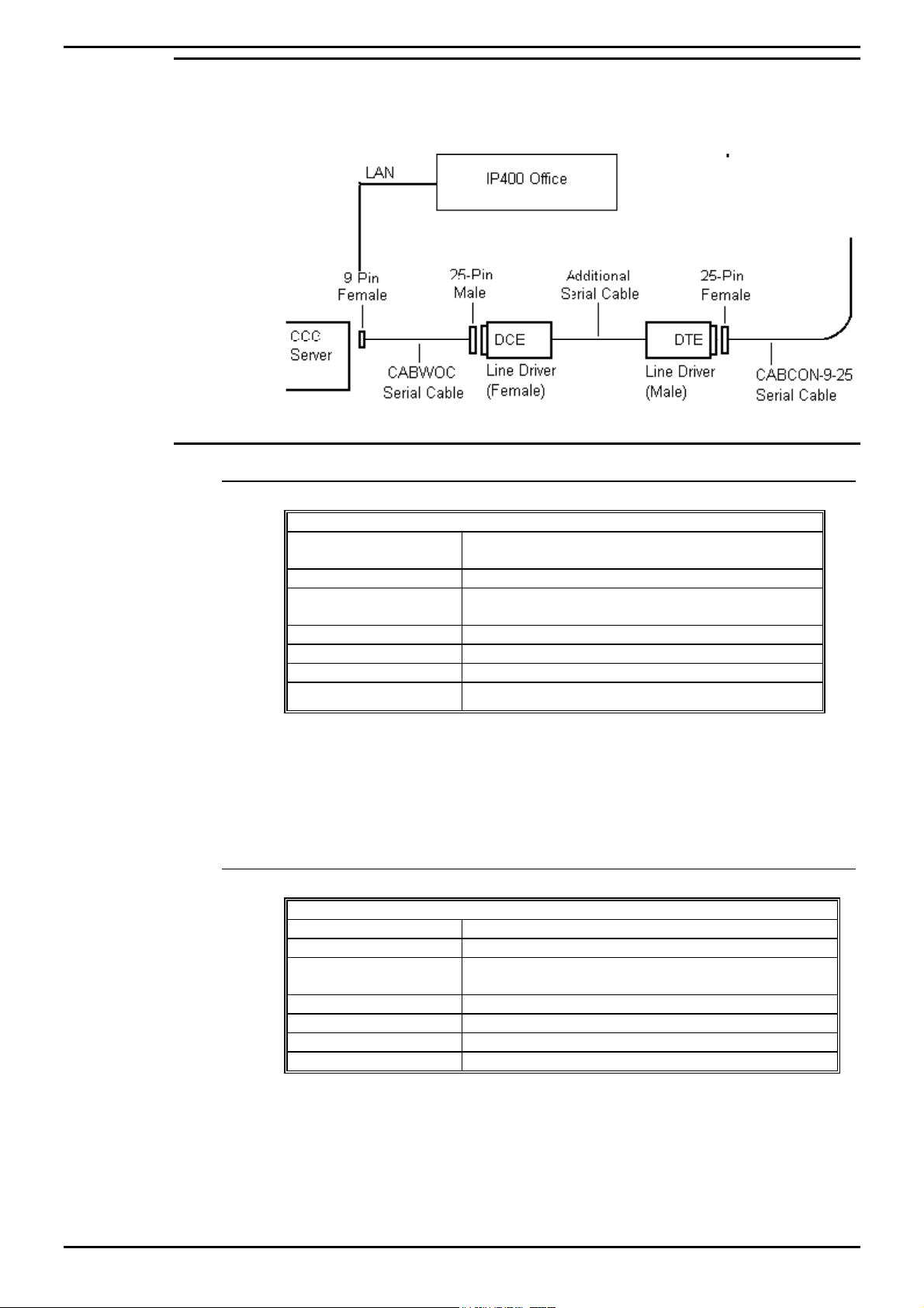
Connecting the CCC Server
The LAN provides connection between the IP400 and the CCC Server. It
will support 10/100 Mbps connection. The length of cable is dependent on
structured cabling and speed.
Wallboard Devices
Wallboard 22
Specification
Voltage
Wattage 108W
Cold Start Inrush
Current
Baud Rate 9600 only
Input RS 485
Weight 6 kg
Dimensions L 1097 x D 75 x H 198 mm
Installation power distribution circuit rating to be greater than 6 amp, any
circuit breakers must be capable of handling the cold start inrush current
without tripping. For details of Wallboard 22 Installation see "Wallboard 22"
on page 6.
Wallboard 10
Specification
Voltage Check label on rear of wallboard
Wattage 35W
Cold Start Inrush
Current
Baud Rate 9600 only
Input RS 485
Weight 4 kg
Dimensions L 469 x D 75 x H 123 mm
220/240V AC OR 110V AC. (Check label on rear of
wallboard)
30A for up to 6ms
30A for up to 6ms
Installation power distribution circuit rating to be greater than 6 amp, any
circuit breakers must be capable of handling the cold start inrush current
without tripping. For details of Wallboard 10 Installation see " Wallboard
10" on page 40.
Compact Contact Center Installation & Maintenance
40DHB0002USBG Issue 1 (11/14/2001) Introduction • Page 6
Page 7

Introduction Limitations
Limitations
15 Agent Systems and below
The Compact Contact Center Manager comprises a suite of tightly
integrated Contact Center Modules installed on a CCC Server PC platform
running Windows 2000 or NT4. The Compact Contact Center Manager
may be installed either with or without Voice Manager Pro. The following
lists the Compact Contact Center modules included within the Compact
Contact Center Manager which are designed to run concurrently on the
CCC Server PC: -
CCC Server PC
−
Call Center View.
−
Wallboard Server.
−
Report Server and Client.
−
Report Designer (optional).
−
Voice Processing Administration (if Voice Manager Pro is present).
The following diagram shows the Compact Contact Center connectivity, for
systems of 15 agents and below, supplied on a standalone PC from Avaya
without a Voice Manager.
The following diagram shows the Compact Contact Center Manager
connectivity, for systems of 15 agents and below, where a Voice Manager
is present.
Compact Contact Center Installation & Maintenance
40DHB0002USBG Issue 1 (11/14/2001) Introduction • Page 7
Page 8

Introduction Limitations
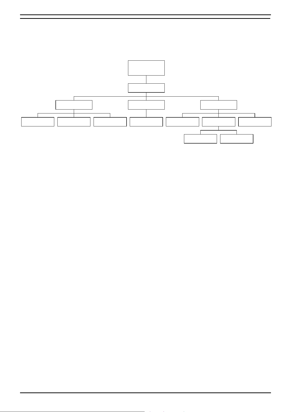
Systems above 15 Agents
Due to the traffic demands of contact centers above 15 agents, the Report
Server and Wallboard Server must reside on a dedicated PC. The product
is offered as a complete solution supplied on 2 PC’s, capable of being
installed on the customer’s existing LAN. The Compact Contact Center
Manager supports 5 concurrent supervisor positions. It may be installed
either with or without a Voice Manager. The following details where the
applications reside:
Client PC Server PC
Call Center View Delta Server
Wallboard Client Report Manager
Report Viewer Wallboard Server
Report Designer (Optional) Report Scheduler
Voice Processing applications Archiver
PC Wallboard
CCV Alarm Reporter
CCC User Access
The diagram below shows the Compact Contact Center Manager without a
Voice Manager being installed.
The diagram below shows the Compact Contact Center Manager where a
Voice Manager is present.
Compact Contact Center Installation & Maintenance
40DHB0002USBG Issue 1 (11/14/2001) Introduction • Page 8
Page 9

PC Configuration Overview
PC Configuration
Overview
The Server PC requires a 4 GB partition for the software applications. The
remaining of the hard drive is used for the Archiver database.
This section details the PC configurations as follows:
1. Server PC configuration using Windows NT 4.0 Server. See "Server
PC Setup – NT4" on page 10.
2. Server PC configuration using Windows 2000. See "Server PC Setup –
Windows 2000" on page 14.
3. Client PC configuration using Windows NT 4.0 Workstation. See
"Client PC Setup - Windows NT Workstation" on page 16.
4. Client PC configuration using Windows 95. See "Client PC Setup Windows 95" on page 17
5. Client PC configuration using Windows 98. See "Client PC Setup Windows 98" on page 18.
6. Client PC configuration using Windows 2000. See "Client PC Setup Windows 2000" on page 19.
Compact Contact Center Installation & Maintenance
40DHB0002USBG Issue 1 (11/14/2001) PC Configuration • Page 9
Page 10

PC Configuration Server PC Setup – NT4
Server PC Setup – NT4
1. Windows NT Server 4.0 Modifications
On a machine with Windows NT4 already installed, you need to check the
following settings.
1 The Computer Name needs to be ARCHIVERSQL.
2 The network protocol is TCP/IP.
3 Windows NT Server Service Pack 6a must have been installed. If you
are in doubt, install the service pack again.
4 Ensure that the Time Zone is set to local time [e.g. for UK set it to
English (United Kingdom)].
5 Make sure that the screen display properties have been set to the
following:
Desktop Area is set to 800 by 600 pixels. Color palette is set to
65536.
1.1 Create the C and SDX Shares
1. Double click on the My Computer Icon.
2. Click the right mouse button on drive C: and select Sharing from the
menu.
3. Click on the New Share button.
4. Enter SDXSHARE (Uppercase) in the Share name and ensure that the
user limit is set at Maximum Allowed.
5. Click on the OK button, then Click on the New Share button.
6. Enter C (Uppercase) in the Share name and ensure that the user limit is
set at Maximum Allowed.
7. Click on the OK button to close the screen.
8. Click on the Apply button and then the OK button.
1.2 Guest Account
1. Click Start; highlight Programs and then Administrative Tools.
2. Click on User Manager for Domains.
3. Double click on the Guest Account. Remove the check from the check
box of "Account Disabled".
4. Click OK and then close the User Manager for Domains screen.
1.3 Event Log Settings
1. Click Start; highlight Programs and then Administrative Tools.
2. Click on Event Viewer. Click Log and then Log Settings.
3. Select System from the drop down list. Select Overwrite Events as
needed.
4. Select Security from the drop down list. Select Overwrite Events as
needed.
5. Select Application from the drop down list. Select Overwrite Events
as needed.
6. Click OK and exit the Event Viewer.
Compact Contact Center Installation & Maintenance
40DHB0002USBG Issue 1 (11/14/2001) PC Configuration • Page 10
Page 11
PC Configuration Server PC Setup – NT4
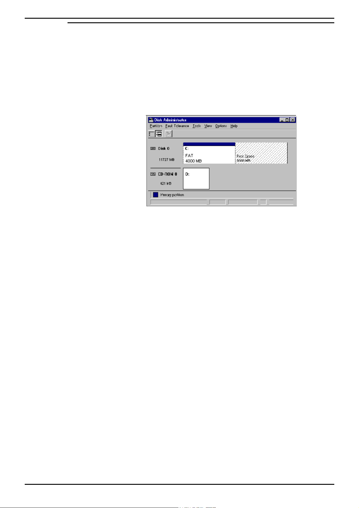
2. Partition the Disk
1. From the Windows Taskbar, click Start, point to Programs, point to
Administrative Tools (Common) and click Disk Administrator.
2. If you are running this application for the first time, a warning screen will
show stating that the system configuration will now be updated. Click
Ok to continue. Click Ok to the confirmations.
3. A graphical representation of all the physical disks connected to your
computer along with their partition appears. A status bar at the bottom
of the window provides basic information on partitions. A color-coded
legend on top of the status bar shows what the different partition colors
and patterns represent.
4. Click the D drive (i.e. CD-ROM).
5. From the Tools menu, click Assign Drive Letter.
6. Click to select Assign Drive Letter, and select letter E.
7. Click OK.
8. From the Confirmation screen, click Yes to continue.
9. From the Partition menu, select Create. Click Yes to continue and
create the partition. The Create Primary Partition screen displays the
size of the partition to be created. This will usually be the maximum
since it will contain all of the free space available. Click OK.
10. From the Partition menu, select Commit Changes Now. Click Yes to
save the changes.
11. Click Yes to save the changes.
12. Click OK to update the Emergency Repair configuration and create a
new Emergency Repair Disk.
13. Click the D drive. From the Tools menu, click Format. Set File System
to NTFS. Click Start to initiate the format request and then click OK to
continue.
14. When the formatting is finished, click OK.
15. From the Format D:\ screen, click Close to return to the Disk
Administrator window.
16. From the Partition menu, click Exit to close the Disk Administrator
application.
Compact Contact Center Installation & Maintenance
40DHB0002USBG Issue 1 (11/14/2001) PC Configuration • Page 11
Page 12

PC Configuration Server PC Setup – NT4
3. Installation of Wallboard Card.
Advantech ISA Wallboard Card Installation
Card Settings: -
JP1 (ch#1) 485
JP2 (ch#2) 485
JP3 (ch#1) IRQ9
JP4 (ch#2) IRQ5
JP5 (ch#1) On
JP6 (ch#2) On
To change the settings:
1. Click Start, highlight Settings and then click Control Panel.
2. Double click the Ports icon.
3. Highlight Port 3 and then click Settings.
4. At the next screen click Advanced.
5. Change Base I/O port address to 3e8.
6. Change IRQ to 5, then click OK.
7. Click Don't restart Now and then click on OK.
8. Highlight Port 4 and click on settings.
9. At the next screen click on Advanced.
10. Change Base I/O Port Address to 2e8.
11. Change IRQ to 9 and then click OK.
12. Click Restart Now.
Advantech PCI Wallboard Card
Card settings: SW1 (CH1) = ON
SW1 (CH2) = ON
JP1 = 485
JP2 = 485
To change the settings:
1. Ensure that the card is not plugged into the PC. If the card is still in the
PC shut down the PC and remove the power leads before removing the
card, otherwise the hard drive may become corrupted.
2. Insert the Advantech PCI drivers utility installation diskette 1 into drive
A.
3. Select Start, and then click on Run.
4. At the next screen type A:\setup.exe and click on OK.
5. At the welcome screen click Next.
6. At the software license screen agreement screen click Yes.
7. At the destination screen accept the defaults and click Next.
8. At program folder accept the defaults and click Next.
9. When prompted insert disk 2 and click on the OK button.
10. At set-up complete screen and click Finish.
11. At Advantech PCI serial Service Manager screen make sure that the
Start/Stop service control is Install and Start Service and then click
OK.
12. Click OK at the next screen.
13. Shut down the computer and install the card into PCI SLOT 4.
Compact Contact Center Installation & Maintenance
40DHB0002USBG Issue 1 (11/14/2001) PC Configuration • Page 12
Page 13

PC Configuration Server PC Setup – NT4
4. Install Database Application
If SQL 2000 is to be installed instead of MSDE, please go to the section
"4.2 Installing Microsoft SQL 2000".
4.1 Installing MSDE 2000
1.
Insert the CCC Installation CD into the drive.
2.
From the Windows taskbar click Start, select Run and then click on the
Browse button.
3.
View the CD drive and double click the MSDE folder. Select
MSDEInst.exe and click on the open button.
4.
Click the OK button to continue.
5.
Select the required language for the installation and then click on the
OK button. The installation could take up to 20 minutes.
6.
Once the setup is complete, reboot the PC when requested.
7.
Once Windows has restarted, installation of service pack 1 for SQL
Server Desktop Engine will automatically begin. Wait for the SQL
Server Desktop Engine screen to show.
8.
Once the service pack installation is complete, reboot the PC when
requested.
4.2 Installing Microsoft SQL 2000
It is possible to install SQL 2000 instead of MSDE. The software is not
supplied as part of CCC and you will need to purchase your own copy, as
Avaya does not supply it.
The following steps will install SQL Server 2000 components:
1.
Insert the SQL Server 2000 compact disc into your CD-ROM drive. If
the compact disc does not auto run, double-click Autorun.exe in the
root directory of the compact disc.
2.
Select SQL Server 2000 Components, select Install Database
Server, and then setup prepares the SQL Server Installation Wizard. If
not installing on Windows NT Server version 4 or Windows 2000
Server a warning message will be displayed stating that only client
components will be available. Click OK. At the Welcome screen, click
Next.
3.
In Computer Name dialog box, Local Computer is the default option
and the local computer name appears in the edit box. Click Next.
4.
In the Installation Selection dialog box, click Create a new instance
of SQL Server, or install Client Tools, and then click Next.
5.
Enter the User Information. Click Next.
6.
Click Yes to accept the software license agreement.
7.
Enter the 25 digit CD-Key. Click Next.
8.
In the Installation Definition dialog, select Client Tools Only.
9.
In the Select Components dialog, select the desired components. It is
recommended that you have Management Tools and Client
Connectivity options selected. Click Next.
10.
In Start Copying Files dialog box. Click Next.
11.
In the Setup Complete dialog box, click Finish.
Compact Contact Center Installation & Maintenance
40DHB0002USBG Issue 1 (11/14/2001) PC Configuration • Page 13
Page 14

PC Configuration Server PC Setup – Windows 2000
Server PC Setup – Windows 2000
1. Windows 2000 Modifications
On a machine with Windows 2000 already installed you need to check the
following:
1 The computer name needs to be ARCHIVERSQL.
2 The network protocol needs to be set to TCP/IP.
3 Ensure that the Regional Options are set to local time [e.g. for UK set it
to English (United Kingdom)].
4 Make sure that the screen display properties have been set to the
following:
•
Desktop area is set to 800 by 600 pixels.
•
Color palette is set to True Color (32 Bit).
5 Install Database Application as detailed in section "4. Install Database
Application" on page 13.
6 Check the Wallboard card jumper settings as given in section "3.
Installation of Wallboard Card." on page 12.
7 Create Shares as described in the section "1.1 Create the C and SDX
Shares" on page10.
2. Guest Accounts
For CCC applications to communicate, the Guest Account on Windows
2000 needs to be enabled. To modify the Guest Account:
1. Click the right mouse button on the My Computer Icon. Select
Manage.
2. Expand the folder Local Users and Groups.
3. Open the Users folder and then double click on Guest.
4. Click on the General Tab. Remove the check by 'Account is disabled'
then click on the Apply button. Click on OK and then close all screens.
3. Event Log Settings
The Event Log settings are altered through the Windows Event Viewer. To
do this:
1. Click the right mouse button on the My Computers Icon. Select
Manage.
2. Expand the Event Viewer folder.
3. Click the right mouse button on Application Log and select properties.
In the Log size section select 'overwrite events as needed'. Click on
Apply and then OK.
4. Click the right mouse button on Security Log and select properties. In
the Log size section select overwrite events as needed. Click on Apply
and then OK.
5. Click the right mouse button on System Log and select properties. In
the Log size section select overwrite events as needed. Click on Apply
and then OK.
6. Close all open windows.
Compact Contact Center Installation & Maintenance
40DHB0002USBG Issue 1 (11/14/2001) PC Configuration • Page 14
Page 15
PC Configuration Server PC Setup – Windows 2000
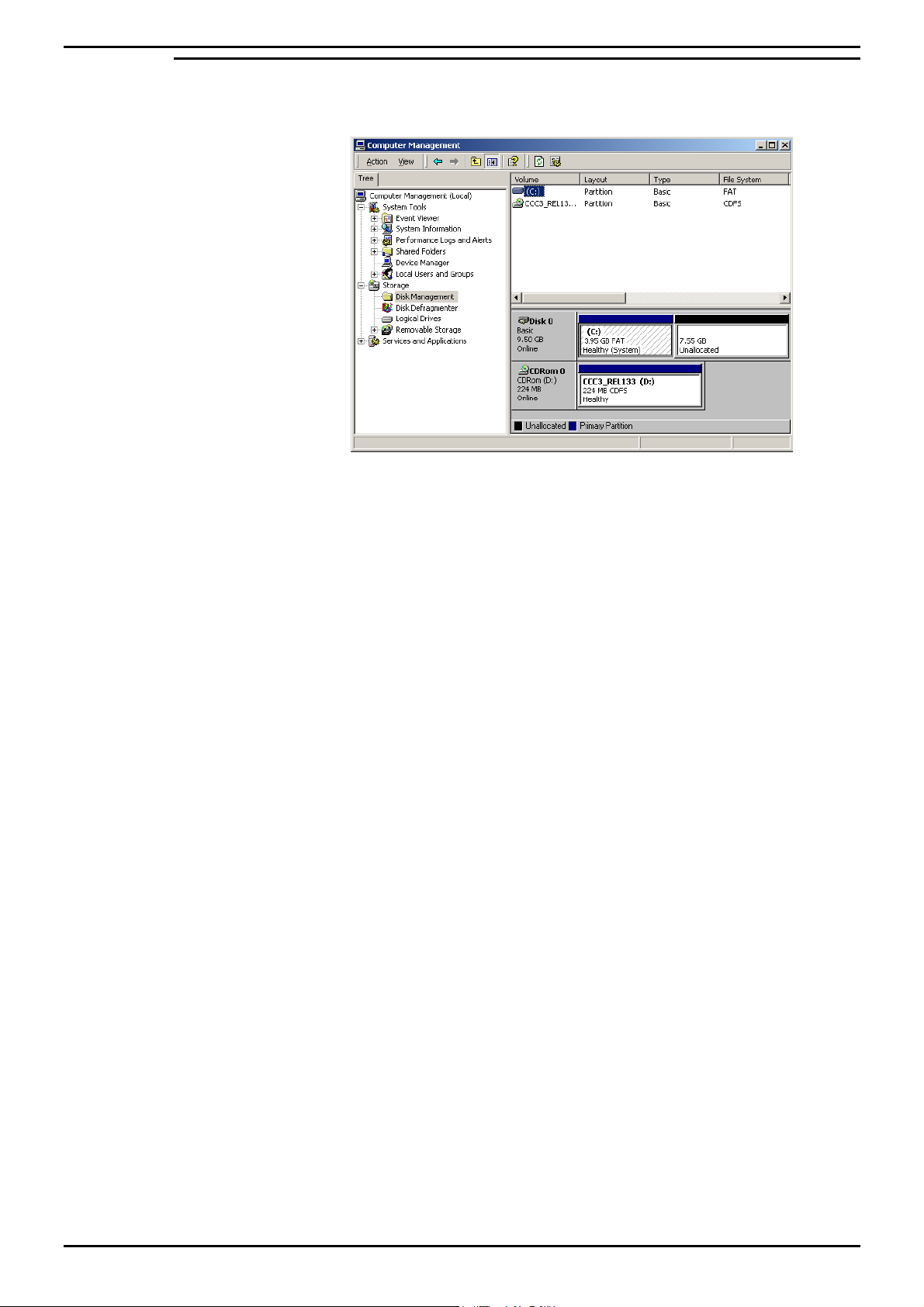
4. Partition the Disk
1.
Click the right mouse button on the My Computer icon. Select Manage
2.
Click on the Disk Management folder.
3.
Click the right mouse button on the CD ROM section, select Change
drive letter and drive path. Click on the edit button.
4.
At the Assign Drive Letter screen, select the drive letter as E. Click on
the OK button to continue.
5.
At the confirmation screen, click Yes to continue.
6.
At the Disk management screen, click Yes.
7.
Click the right mouse button on the unallocated section of Disk O, select
Create Partition.
8.
At the welcome screen click Next.
9.
At the Create Partition type screen select Primary, click on Next to
continue.
10.
At the Specify Partition Size screen accept the default size and click on
Next.
11.
At the Assign Drive letter or Path screen, do not assign a drive letter or
path and click on Next to continue.
12.
At the format partition screen, select Perform a Quick Format and
accept all other defaults. Click on Next to continue.
13.
At the completed screen click on the Finish button.
14.
Click the right mouse button over the new volume, select change drive
letter, and drive path.
15.
Click on Add and assign the letter D.
You are now ready to install CCC applications, see "Install CCC
Applications" on page 20.
Compact Contact Center Installation & Maintenance
40DHB0002USBG Issue 1 (11/14/2001) PC Configuration • Page 15
Page 16

PC Configuration Client PC Setup - Windows NT Workstation
Client PC Setup - Windows NT Workstation
1. Windows NT Workstation Modifications
On a machine with Windows NT4 workstation already installed you need to
check the following:
1.
The Computer Name must NOT be ARCHIVERSQL.
2.
Windows NT Server Service Pack 6a has been installed. If you are in
doubt, install the service pack again.
3.
Ensure that the Time Zone is set to local time [e.g. for US set it to
English (United States)].
4.
Make sure that the screen display properties have been set to the
following:
•
Desktop Area is set to 800 by 600 pixels
•
Color palette is set to 65536.
5.
Ensure that a guest account has been enabled as described in section
"1.2 Guest Account" on page 10.
6.
Amend the Event log settings as described in section "1.3 Event Log
Settings" on page 10.
2. Map Network Drive
1. From the Windows NT desktop, click (using the right mouse button)
Network Neighborhood and select Map Network Drive.
2. Select a Map Drive (e.g. E:), in the Path Type \\ARCHIVERSQL\C,
ensuring Reconnect at logon is also checked.
3. Click OK. This enables you to share the CCC (e.g. Call Center View)
files.
You are now ready to install CCC applications as detailed on "Install CCC
Applications" on page 20.
Compact Contact Center Installation & Maintenance
40DHB0002USBG Issue 1 (11/14/2001) PC Configuration • Page 16
Page 17

PC Configuration Client PC Setup - Windows 95
Client PC Setup - Windows 95
1. Windows 95 Modifications
On a machine with Windows 98 already installed, the following settings are
required:
1.
The Computer Name must NOT be ARCHIVERSQL.
2.
Ensure that the Regional Settings are set to local time [e.g. for UK set it
to English (British)].
3.
Make sure that the screen display properties have been set to the
following:
•
Desktop Area is set to 800 by 600 pixels
•
Color palette is set to 65536.
2. Map Network Drive
1. From the Windows 95 desktop, click (using the right mouse button)
Network Neighborhood and select Map Network Drive.
2. Select a Map Drive (e.g. E:), in the Path Type \\ARCHIVERSQL\C,
ensuring Reconnect at logon is also checked.
3. Click OK. This enables you to share the CCC (e.g. Call Center View)
files.
You are now ready to install CCC applications as detailed on "Install CCC
Applications" on page 20.
Compact Contact Center Installation & Maintenance
40DHB0002USBG Issue 1 (11/14/2001) PC Configuration • Page 17
Page 18

PC Configuration Client PC Setup - Windows 98
Client PC Setup - Windows 98
1. Windows 98 Modifications
On a machine with Windows 98 already installed, the following settings are
required:
1 The Computer Name must NOT be ARCHIVERSQL.
2 Ensure that the Regional Settings are set to local time [e.g. for UK set it
to English (British)].
3 Make sure that the screen display properties have been set to the
following:
•
Desktop Area is set to 800 by 600 pixels
•
Color palette is set to 65536.
2. Map Network Drive
1. From the Windows 98 desktop, click (using the right mouse button)
Network Neighborhood and select Map Network Drive.
2. Select a Map Drive (e.g. E:), in the Path Type \\ARCHIVERSQL\C,
ensuring Reconnect at logon is also checked.
3. Click OK. This enables you to share the CCC (e.g. Call Center View)
files.
You are now ready to install CCC applications as detailed on "Install CCC
Applications" on page 20.
Compact Contact Center Installation & Maintenance
40DHB0002USBG Issue 1 (11/14/2001) PC Configuration • Page 18
Page 19

PC Configuration Client PC Setup - Windows 2000 Professional.
Client PC Setup - Windows 2000 Professional.
1. Windows 2000 Modifications
On a machine with Windows 2000 Professional already installed, the
following settings are required:
1 The Computer Name must NOT be ARCHIVERSQL.
2 Ensure that the regional options are set to local time [e.g. for UK set it
to English (United Kingdom)].
3 Make sure that the screen display properties have been set to the
following:
•
Desktop Area is set to 800 by 600 pixels
•
Color palette is set to 65536.
4 Ensure that the guest account has been enabled. Refer to "2. Guest
Accounts" on page 14.
5 Alter the Event Log settings as described in section "3. Event Log
Settings" on page 14.
2. Map Network Drive
1. From the Windows desktop, Click the right mouse button on the My
Computer icon and select Map Network Drive.
2. Select a Map Drive (e.g. F).
3. In the Folder section type \\ARCHIVERSQL\C
4. Make sure that the Reconnect at logon is also checked. Click on
Finish. This enables you to share the CCC (e.g. Call Center View)
files.
You are now ready to install CCC applications as detailed on "Install CCC
Applications" on page 20.
Compact Contact Center Installation & Maintenance
40DHB0002USBG Issue 1 (11/14/2001) PC Configuration • Page 19
Page 20

Install CCC Applications Installing CCC
Install CCC Applications
Installing CCC
This section describes the procedures of installing the software for the
Compact Contact Center suite. If there is another server called
ARCHIVERSQL on the network, then install the CCC applications without
the server plugged to the network.
Note: If Internet Explorer is on the same PC or server as the delta server software,
you must make sure that where there is an Internet service that there is also an
Internet user.
Listed below are the required CCC applications required depending on your
hardware setup.
Server PC: Client PC Standalone Server
Delta Server Report Client Delta Server
Report Scheduler Wallboard Client Wallboard Server
Report Manager CCV Alarm Reporter Report Manager
Wallboard Server Call Center View Call Center View
PC Wallboard PC Wallboard
Report Client
CCV Alarm reporter
To install the applications:
1.
With Windows running, insert the Application CD into the CD Drive. It
should Autostart. If this does not happen use the My Computer facility
to view the CD drive. Double click on Setup.exe.
2.
Choose the appropriate setup language and click on OK.
3.
At the Welcome screen click on Next to continue.
4.
Select a full installation and click Next to continue.
5.
Select the applications that you want to install. Click Next to continue.
6.
Installation will start. During the process you will be asked, "You are
about to configure an Archiver to 2000MB. Continue?" Click on the
Yes button.
7.
Installation will start. Part way through the installation process a
message will show saying "Installation Complete". Click on the OK
button and then further components will be installed.
8.
A message will show saying that the installation is complete. Click on
the OK button.
9.
At the InstallShield Wizard installation complete screen, select to
Restart the computer and then click on the Finish button.
10.
Re-boot the PC.
Note:
1. After logging onto a newly started Server PC, Delta Server and Archiver will all
start automatically. These are all timed starts and will take 1-2 minutes.
2. If you are using NT4, you will need to install Service Pack 6a level and restart
the PC.
Compact Contact Center Installation & Maintenance
40DHB0002USBG Issue 1 (11/14/2001) Install CCC Applications • Page 20
Page 21

Trouble Shooting CCC Installation
Trouble Shooting
CCC Installation
1. Whenever anything is loaded from the I386 directory on a Windows
NT4 installation CD, re-installation of NT4 Service Pack 6a is
NECESSARY.
2. On the Server PC, ensure that the guest account is enabled. Also,
ensure that the C drive is shared with the names ‘C’ and ‘SDXSHARE’.
Shares must have full permissions.
3. If, for whatever reason, the Server PC has to be renamed from the
default name (ArchiverSQL), be aware that Microsoft SQL cannot be
guaranteed to operate correctly if a name that includes spaces is used.
CCC Client applications
1. It is possible that a Client application will NOT automatically find the
Delta Server, if the Client application and Delta Server are on PCs on
different networks. When this happens, click the ‘Advanced’ button
(from Find Server screen) and select the option to enable the name of
the PC running the Delta Server to be typed in.
2. When using Microsoft Windows 98, for Client applications mapping a
drive to the C drive on the Server PC will speed up Server discovery.
3. When using a Global/Seltek Voice Manager for queuing which uses the
traditional pickup method, the number of calls presented along with the
answer time statistics for an agent/agent group may not be as expected.
Report Manager
1. To be sure that the Archiver is passing information into the database it
is a good idea to keep the status window displayed.
Wallboard Server/Client
1. On the Wallboard Server/Client, a User can only remove scheduled
messages from the schedule with a higher access level than the User
that scheduled the message or by the user that scheduled the
message. It therefore follows that if a user with Administrator access
rights has scheduled a message then only that User can remove that
message from the schedule.
Compact Contact Center Installation & Maintenance
40DHB0002USBG Issue 1 (11/14/2001) Trouble Shooting • Page 21
Page 22

CCC User Access Starting CCC User Access
CCC User Access
Starting CCC User Access
To log on using CCC User Access:
1.
Double click on the CCC User Access Icon showing at the bottom right
of the screen
the desktop and then double click on the Icon which should now be
visible.
2.
A CCC User Access screen will show. Any user name can be entered
to give system supervisor rights. When the update button becomes
active, click on it to update the repository.
If you put the user name as Admin, a password box is displayed. When
you log on as Administrator for the first time, it is recommended that you
change the password. To do this click on the New Password button, enter
your new password and confirm the change.
If this is not visible double click the Icon on
.
Until you change the password, Administrator can be logged on by entering
the following:
Name: Admin
Password: NMYSBH
Administrator Rights System Supervisor
Rights
System Administrator
functions available.
Ability to change ALL
setup screens.
Ability to change the
language in CCV.
CCV Alarm Reporter can
be run.
Ability to change the
language in CCV.
Ability to change some
setup screens.
No Name
No setup
screens
available
Compact Contact Center Installation & Maintenance
40DHB0002USBG Issue 1 (11/14/2001) CCC User Access • Page 22
Page 23

Change Server PC Name Overview
Change Server PC Name
Overview
It is vital that the Server PC used to run the CCC modules is called
ARCHIVERSQL whilst installing the applications. Once the installation is
complete, change the PC name and workgroup name if desired, as detailed
in this section, prior to connecting the PC to the network.
The following procedure has to be performed after the CCC applications
have been installed on the relevant PCs. However you must ensure none
of the CCC applications are running.
NT4 Server PC
Change Server PC Name
Make sure that there are no programs running on the server then follow the
instructions below.
1. From the Windows Taskbar, click Start, point to Settings and select
Control Panel, double click Network,
2. From the Identification tab click Change.
3. Type your computer name as required. Click OK.
4. From the Identification tab, click OK to confirm.
5. When prompted, click Yes to restart the PC.
6. If you are using MSDE you will need to re-install it as detailed in section
"4.1 Installing MSDE 2000" on page 13 and then proceed to the section
"Change ODBC Settings" on page 24.
If you are using SQL 2000 continue to following the instructions given
below.
7. From the Windows Taskbar, click Start, point to Programs, select SQL
Server, and then select SQL Query Analyzer.
8. Enter the new PC name in the SQL Server field.
9. Select the SQL Server Authentication option and enter sa as the Login
name, leaving the password field empty.
10. Click OK
11. Execute the following command
sp_dropserver ARCHIVERSQL
12. Execute the following command
sp_addserver # # # # # # # # # #,LOCAL
(e.g. if the server PC has been renamed as ARCHIVERSQL123 enter
sp_addserver ARCHIVERSQL123,LOCAL.)
13. Re-boot the Server PC.
14. Now proceed to the section "Change ODBC Settings" on page 24.
Compact Contact Center Installation & Maintenance
40DHB0002USBG Issue 1 (11/14/2001) Change Server PC Name • Page 23
Page 24

Change Server PC Name NT4 Server PC
Change ODBC Settings
Ensure you perform the following procedure for both the SDXArchiver and
SDXRepository System Data Sources.
1. From the Windows Taskbar, click Start, point to Settings and select
Control Panel.
2. From the Control Panel, open ODBC, and click System DSN tab. The
ODBC Data Source Administrator screen appears.
3. Select SDXArchiver and then click Configure.
4. In the Description box, enter the new Server name (e.g. if the PC
name has been changed to ARCHIVERSQL123, then in the above
screen, SDXArchiver on server ARCHIVERSQL changes to
SDXArchiver on server ARCHIVERSQL123).
5. In the Server box, enter the new server name (e.g.
ARCHIVERSQL123), click Finish.
6. Click Test Data Source to ensure the configuration is created and then
click OK.
7. Select SDXRepository and then click Configure.
8. In the Description box, enter the new Server name (e.g. if the PC
name has been changed to ARCHIVERSQL123, then in the above
screen, SDXArchiver on server ARCHIVERSQL changes to
SDXArchiver on server ARCHIVERSQL123).
9. In the Server box, enter the new server name (e.g.
ARCHIVERSQL123), click Finish.
10. Click Test Data Source to ensure the configuration is created and then
click OK.
11. From the ODBC Data Source Administrator screen, click OK.
Compact Contact Center Installation & Maintenance
40DHB0002USBG Issue 1 (11/14/2001) Change Server PC Name • Page 24
Page 25

Change Server PC Name Windows 2000 Server
Windows 2000 Server
Change Server PC Name
Make sure that there are no programs running on the server then follow the
instructions below.
1. Click the right mouse button on the My Computer icon. Select
properties.
2. Click on the Network Identification tab.
3. Click on the Properties button.
4. Type your computer name as required. It needs to be 15 characters or
less. Click OK to confirm name change.
5. Re-start your computer.
6. Once the PC has restarted, an error screen may appear stating that you
cannot reach repository database. Click OK.
7. Close all the CCC applications.
8. Click on the Windows Start button; highlight Programs,
Administrative Tools and click Data Sources (ODBC).
9. Click on the Configure button.
10. Click on the System DSN tab.
11. Highlight SDXARCHIVER and click on the Configure button.
12. In the section that asks "Which SQL Server do you want to connect
to?", select the new Computer name from the drop down box.
13. Change the description of the data source to reflect the new name if
required.
14. Click on the Finish button.
15. Click on the OK button.
16. Highlight SDX REPOSITORY and click on the Configure button.
17. In the section which asks "Which SQL Server do you want to connect
to?", select the new Computer name from the drop down box.
18. Change the description of the data source to reflect the new name if
required.
19. Click on the Finish button.
20. Click on the OK button.
21. Close all open screens.
22. Re-boot the computer.
Compact Contact Center Installation & Maintenance
40DHB0002USBG Issue 1 (11/14/2001) Change Server PC Name • Page 25
Page 26

Change Client PC Names General
Change Client PC Names
General
Once the Server PC name has been changed you will need to change the
references to the server PC on the Client PC's. The following sections
details the procedure depending upon the operating system being used on
the client machine.
Operating Systems
Windows NT Workstation
The ODBC settings of the SDXArchiver and SDXRepository databases
need to be changed. This is detailed in the section "Change ODBC
Settings" on page 24.
Windows 95/98
Make sure that there are no programs running on the PC then follow the
instructions below.
1. From the Windows Taskbar, click Start, point to Settings and select
Control Panel.
2. From the Control Panel, double click on ODBC Data Source (32bit)
and click System DSN tab.
3. Select the SDXArchiver and then click Configure.
4. In the Description box, enter the new Server name (e.g. if the PC
name has been changed to ARCHIVERSQL123, then in the above
screen, SDXArchiver on server ARCHIVERSQL changes to
SDXArchiver on server ARCHIVERSQL123).
5. In the Server box, enter the new server name (e.g.
ARCHIVERSQL123), and click OK.
6. Select SDXRepository and then click Configure.
7. In the Description box, enter the new Server name (e.g. if the PC
name has been changed to ARCHIVERSQL123, then SDXArchiver on
server ARCHIVERSQL changes to SDXArchiver on server
ARCHIVERSQL123).
8. In the Server box, enter the new server name (e.g.
ARCHIVERSQL123), and click OK
9. From the ODBC Data Source Administrator screen, click OK.
Compact Contact Center Installation & Maintenance
40DHB0002USBG Issue 1 (11/14/2001) Change Client PC Names • Page 26
Page 27

Change Client PC Names Operating Systems
Windows 2000
Make sure that there are no programs running on the PC then follow the
instructions below.
1. Click on the Windows Start button; highlight Programs,
Administrative Tools and click Data Sources (ODBC).
2. Click on the Configure button.
3. Click on the System DSN tab.
4. Highlight SDXARCHIVER and click on the Configure button.
5. In the section which asks "Which SQL Server do you want to connect
to?" , select the new Computer name from the drop down box.
6. Change the description of the data source to reflect the new name if
required.
7. Click on the Finish button.
8. Click on the OK button.
9. Highlight SDX REPOSITORY and click on the Configure button.
10. In the section which asks "Which SQL Server do you want to connect
to?", select the new Computer name from the drop down box.
11. Change the description of the data source to reflect the new name if
required.
12. Click on the Finish button.
13. Click on the OK button.
14. Close all open screens.
15. Re-boot the computer.
Compact Contact Center Installation & Maintenance
40DHB0002USBG Issue 1 (11/14/2001) Change Client PC Names • Page 27
Page 28

Administering the Database Overview
Administering the Database
Overview
If you have installed the MSDE database, four scheduled tasks are installed
automatically. The parameters cannot be configured, listed below is a
description of each scheduled task's function. If you have purchased and
installed Microsoft SQL 2000 you can use the tools provided to create and
schedule backups etc.
Disk Backup
This task is enabled by default and scheduled to run once a week on a
Sunday at 2 am. It backs up the SDXArchiver database to the default
backup directory, which is d:\microsoft sql\server\mssql\backup. At the
same time any backup that is more than 4 weeks old is deleted.
Tape Backup
This task is disabled by default and cannot be used when only the MSDE
database is installed.
Integrity Check
This task is enabled by default and is scheduled to run once a week on a
Sunday at 1 am. It checks for any problems/corruption in the SDXArchiver
database and automatically fixes any minor faults that are found without
affecting any data.
Optimizations
This task is enabled by default and is scheduled to run once a week on a
Sunday at 1 am. For each table in SDXArchiver, a 10% sample of the data
is taken and used to update the statistics used by the query optimize (an
engine used to analyze queries and determine the quickest way to return
the data being queried for).
Restore
If needed to restore from a backup created above, please contact your field
engineer for help.
Compact Contact Center Installation & Maintenance
40DHB0002USBG Issue 1 (11/14/2001) Administering the Database • Page 28
Page 29

Telephone System Requirements
Telephone System
Requirements
This section assumes that the installer is familiar with the basic
programming of the Telephone System and the Programming manual is
available.
•
Telephone System Software must be Level 3.0 or higher.
•
When using CCC applications, you can only use
4600/4400/2050/20CC handsets with ACD Agents logged on and
Turret devices. However, Report Client obtains information on all
devices.
•
Server Licenses are required for the applications. Listed below are the
software license names as shown within manager.
Names in Manager Description
CCC Server Allows CCC to operate with the first 5 agents and
the first supervisor position. With this license you
get:
1 x Call Center View
1 x Wallboard Server
1 x Archiver
1 x Report Designer
1 x Report Viewer
1 x PC Wallboard.
CCC Agents Required for each additional 10 agents
CCC Supervisor Required for each extra supervisor position giving
CCC Soft Agent Enables PC Wallboard to be used
Naming Directory Numbers
Since the Telephone System programming is reflected within the Compact
Contact Center Manager applications, it is important to name the directory
numbers (i.e. Agents, Groups, Trunks, DIDs, etc.).
It is also highly recommended that the directory names be unique to aid
identification of specific directory number within the Standard Reports.
Where directory numbers of a specific type are unnamed, or when more
than one directory number as a specific type has the same name, the
Standard Reports will group data for those directory numbers as a single
entity (e.g. all unnamed agents will be grouped together as a single agent
called "No Name", and all DIDs named "Company DID" will be grouped
together as a single DID called "Company DID, etc.).
If the directory numbers have not been named, then the terminology for the
directory numbers implemented in the Contact Center Manager
applications is:
access to report viewer and call center view.
•
Agent – ACD Agent (XXXX*) – XXXX
•
Group – Agt Group (XXXX) – XXXX
•
Trunk Grp – Trunk GP (XXXX) – XXXX
•
Tie Line (Trunk) – Tie Line (XXXX) – XXXX
•
DPNSS (Trunk) – DPNSS (XXXX) – XXXX
•
DASS (Trunk) – DASS (XXXX) – XXXX
•
POTS(TWC) – Alog (TWC) (XXXX) – XXXX
* Where XXXX is the directory number.
Compact Contact Center Installation & Maintenance
40DHB0002USBG Issue 1 (11/14/2001) Telephone System • Page 29
Page 30

Telephone System Requirements
Group Reporting
When configuring it is important to understand how calls are attributed to
groups on the Call Center View, Wallboards and Report Manager.
IP400 in the Contact Center Environment
Staff Management is a LOCAL issue hence all real time and historic
analysis for teams will require local CCC’s.
Traffic Management is a GLOBAL issue. Therefore in an IP400
configuration calls waiting across an entire network (queued) are displayed
on all Call Center View implementations across IP400.
Call Center View and Wallboard Manager
The Call Center View and Wallboard Manager products report on groups
directly derived from the Database. Agents and Trunks may be reported on
in as many groups as they are members of within the database. It is
important however to understand how statistics for these groups are
derived and it is important for the user of the system to understand these
reporting structures. These are defined below
Call Totals and average durations for Groups are calculated by totalling
the statistics for the members of group. Should an agent or group be a
member of multiple groups, their call totals will appear in multiple groups.
Lost Calls are only attributed to the initial target agent group i.e. Initial ring
group. Lost calls are also attributed to Trunk Lines, and Trunk Groups.
Agent Status Information for a group shows the number of agents or
trunks within a given group, which are in each state.
Agent Statistics for:
Calls Waiting, PCA, GOS, Longest Wait, LWait (Ans), L Wait (Lost),
Overflowed to/From statistics are only incremented for calls which are
directly presented to that agent group. That is they only increment
where the agent group is used for Call routing purposes.
Trunk Statistics for:
Calls waiting and Lost are calculated by totalling the statistics for the
members of the trunk group.
PCA and GOS are calculated for each trunk group after totaling
answered calls (plus lost for GOS) for the members of the trunk group.
LWait (Lost) and LWait (Ans) reflect the longest wait of all those
logged against any member of the trunk group.
Report Manager
The CCC has two concepts for historic reporting that cater for different
views a supervisor may require of their contact center. One type of report
referred to as ‘Target’ reports provides analysis based on where the call
was presented and relates closely to the manner in which the call routing
has been configured. The second type of report, referred to as ‘collective’
reports, is based on arbitrary sets of agents and need not necessarily
correspond to the manner in which switch call routing is programmed.
Compact Contact Center Installation & Maintenance
40DHB0002USBG Issue 1 (11/14/2001) Telephone System • Page 30
Page 31

Telephone System Requirements
CCC reporting characteristics associated with Voice Manager
The following conditions apply to the initial answer/ lost segment of calls
which were first presented to the Voice Manager (VM) (e.g. Voice Mail front
ended systems):
1. Trunk/DID – Call remains unanswered until answered by non-Voice
Manager device or if terminated within 3
rd
party Voice Mail, or
encountered an "Answered" flag in Voice Manager.
rd
2. 3
Party Voice Mail – Answered if Voice Mail connects, lost by Voice
Mail if caller hangs up before Voice Mail can answer.
3. Voice Manager – Calls will only be registered as answered when the
Voice Manager has successfully processed the call (passed an
"Answered" flag in Call Flow)
4. Agent/Agent Group – Designation of answered and lost calls is directly
dependent upon clause 1.
5. If a call was lost whilst being transferred by Voice Manager, the lost call
statistics will be designated to the transfer target. Calls lost whilst
alerting or connected to Voice Manager will be deemed lost by the
Voice Manager device or group.
6. A call successfully transferred by Voice Manager will be treated as a
new incoming call by trunks, DID and Agents, but transferred by Voice
Manager devices.
Note: A call, which is first connected to Voice Manager but not deemed answered
by VM, will be considered lost, but not refused if terminated during first connection
to VM.
Compact Contact Center Installation & Maintenance
40DHB0002USBG Issue 1 (11/14/2001) Telephone System • Page 31
Page 32

Wallboard Installation and Maintenance Wallboard 22
Wallboard Installation and Maintenance
Wallboard 22
Introduction
The Wallboard 22 is a two line by 22-character tri-color Wallboard. It
connects via a multi-drop circuit to the host PC running the Wallboard
Server application.
The display wallboard consists of the following assemblies.
Housing: A housing that is manufactured from an aluminum extrusion with
anti reflective polycarbonate screen and removable plastic end caps.
Power Supply: 9V DC switch mode power supply assembly incorporating
an RJ45 chassis mounted data connector. The power supply is
configurable for use from either 120V AC or 240V AC (NOMINAL
VOLTAGES) supplies.
Installation
Logic Control Board: Logic control board that receives RS485 serial data
from the data RJ45 connector.
Display Board Assembly: Tri-color display board assembly, which
consists of three display boards which, are connected one to the other by a
fiber optic link. The left-hand display board receives display data from the
logic control board, via a fiber optic link and it outputs data to the next
display board etc.
Each display board consists of decoding and LED row and column circuitry
which drives the LED matrix consisting of 18 5x8 LED blocks.
Before commencing installation, please check from the packing list that all
parts are included.
Packing List:
1 x Wallboard 22
2 x Wall mount brackets
2 x Spun hanging wires
4 x Cavity rawl plugs
4 x Screws
2 x Eyehole bolts
2 x Masonry rawl plugs
2 x Housing clamps
1 x RJ45 Terminal Box
1 x IEC Power lead
Before commencing installation, please take a couple of minutes ensuring
that the final location of the display will be both safe and practical for the
customer. Also check that the power socket provided is suitable for this
type of display.
Compact Contact Center Installation & Maintenance
40DHB0002USBG Issue 1 (11/14/2001) Wallboard Installation and Maintenance • Page 32
Page 33

Wallboard Installation and Maintenance Wallboard 22
Wall Mounting
Once a location has been decided upon, mark its location on the wall with a
pencil through the two holes in the brackets. Before drilling the holes, a
suitable utility detector should be used. Once this has been done, the
holes may be drilled and the brackets mounted using the relevant fixings
provided.
Before mounting the display onto the brackets, the network address should
be assigned. The power lead should also be attached prior to mounting.
To mount the display, first hook the bottom of the two brackets into the
bottom rear recess channel of the display. See the diagram shown below.
Push the wallboard flat against the wall and push upward to fully locate the
bottom half into the recess. Now allow the display to fall approximately one
inch. The display should now be safely located onto the two brackets.
To remove a wall mounted display then reverse the above paragraph.
Note: The wallboard position can be adjusted by sliding sideways in either
direction.
Ceiling Mounting
Using the mounting kit provided, firstly, drill the 6-mm holes for the eyehole
bolts and secure them into the ceiling. Pass the spun wire chain through
the eyeholes and through the housing clamps and tighten at the required
height.
Remove the right hand end cheek of the wallboard by unscrewing the two
fixing screws.
Slide the two nipples on the end of the spun wire chain into the middle
groove of the display housing and replace the end cheek. Center the
display on the hanging wires. Adjustments can be made by sliding the
display to achieve the final level.
Warning
Ensure the ceiling can support the weight of the wallboard prior to fixing.
Compact Contact Center Installation & Maintenance
40DHB0002USBG Issue 1 (11/14/2001) Wallboard Installation and Maintenance • Page 33
Page 34

Wallboard Installation and Maintenance Wallboard 22
RS485 Serial Connection
The RJ45, RS485 flying lead is one meter long. It cannot be removed from
the Wallboard; therefore, this must be taken into consideration for the
location of the RJ45 terminal box.
Fit the RJ45 terminal box within one meter of the center of the Wallboard.
The Wallboard should be connected to the host system by utilizing a drop
off wiring configuration (See the diagram below).
All RJ45 sockets should be wired identically with the terminated RJ45 plug
on the final socket with the supplied RJ45 doubler.
Network Addressing
Each display can be configured to display different messages. This is
achieved by allocating each display its own network address. Within each
display, there is a board containing eight dip-switches. For more
information see the section entitled "Serial Connection & Dip-Switch
Details" on page 37.
Compact Contact Center Installation & Maintenance
40DHB0002USBG Issue 1 (11/14/2001) Wallboard Installation and Maintenance • Page 34
Page 35

Wallboard Installation and Maintenance Wallboard 22
Additional Equipment
External Alarm Device for connection to Wallboard 22 only.
An external alarm device is available to supplement the in-built buzzer.
This interface allows a DC powered device to be attached to a couple of
pins provided by a 6-pin DIN connector, which is mounted on the rear of the
display. This 6-pin DIN port provides the ability to connect the additional
device in addition to the internal buzzer.
Connection Details
The external 6-pin DIN connector is located adjacent to the Mains Power
Lead (IEC Connector). The pins are numbered on the connector from 1-6.
Port 1 will replicate the internal buzzer, and should be used for buzzers.
Ports 2 and 3 are not used at this point.
Socket View
6 Pin Mini-DIN
The overall connection schematic looks like this:
Compatible External Devices
All of the devices below are available from the Farnell Electronics
Catalogue, and have been tested by Ferrograph and are recommended as
suitable for connection to the external interface.
Note: This external interface has been designed for connection of DC Voltage
devices ONLY.
Continuous/Pulsed Single Tone Sounders – 12V & 24V DC
Farnell Reference: FEC143-400
FEC143-402
FEC143-403
Compact Contact Center Installation & Maintenance
40DHB0002USBG Issue 1 (11/14/2001) Wallboard Installation and Maintenance • Page 35
Page 36

Wallboard Installation and Maintenance Wallboard 22
Periodic Maintenance and Inspection
Cleaning Display Screen
Time periods between cleaning depend upon local conditions and are at
the discretion of the operator. This routine cleaning can be carried out in
the normal way using a damp and/or dry cloth.
Note: This screen is specially coated to reduce reflections and although this
coating is very durable misuse or incorrect cleaning, procedures can damage it.
LED Illumination Test Inspection
The purpose of this test is to ensure no LED fails to illuminate and should
be checked annually.
Remove the left-hand end cheek and carefully slide out the logic control
board so that the dip-switches are accessible. Set switch 8 to ON, inspect
the LED display that will run blocks of Green, Red and Yellow across the
display. Look for any LED's that fail to illuminate.
Return switch 8 to the OFF position to stop this test.
LED Matrix Scanning Inspection
The purpose of this inspection is to ensure the LED matrix is being scanned
correctly. Remove the left-hand end cheek and carefully slide out the logic
control board so that the dip-switches are accessible.
Set switch 7 to ON, Yellow diagonal stripes will run across the display.
Check that these stripes are straight and that Yellow is the only color
displayed. Having completed this visual inspection return switch 7 to OFF
and ensure that all switch settings comply with system requirements for
baud rate and wallboard network address number. See Section D for dipswitch details.
Compact Contact Center Installation & Maintenance
40DHB0002USBG Issue 1 (11/14/2001) Wallboard Installation and Maintenance • Page 36
Page 37

Wallboard Installation and Maintenance Wallboard 22
Serial Connection & Dip-Switch Details
Wallboard Terminal Box RJ45 Connector Pin Out Details
Pin
2 Signal Ground
3 Sign Rx+ Input
4 Sign Tx+ Output
5 Sign Tx- Output
6 Sign Rx- Input
7–
Pin out Connections
Wallboard x RJ45 Socket Wallboard x+1 RJ45 Socket
Pins from 2 to 7 should be connected identically from all RJ45 boxes to all
others.
Dip-Switch Details
Network Address
OFF Position Represents 0
ON Position Represents 1
SW4 SW3 SW2 SW1 ADDRESS
00000
00011
00102
00113
01004
01015
01106
01117
10008
10019
101010
101111
110012
110113
111014
111115
Compact Contact Center Installation & Maintenance
40DHB0002USBG Issue 1 (11/14/2001) Wallboard Installation and Maintenance • Page 37
Page 38

Wallboard Installation and Maintenance Wallboard 22
Baud Rate
Dip Switch Settings are:
SW5 SW6 DATA BIT/SEC
OFF OFF 19200
ON OFF 9600
OFF ON 2400
ON ON 1200
Ensure the Baud rate is set to 9600.
Test Functions
SW7 SW8 FUNCTION
OFF OFF Normal Running
ON OFF Diagonal Stripe Test
OFF ON Full Screen LED Test
ON ON Information Screen
(Only on power up)
The information screen shows three pages where the following text is
displayed. The dip switches must be set with the display powered down,
then switch power on to achieve information screen.
Yellow Text Software Version
Sign Type
Green Text Network
Number
Red Text Baud
Rate
Compact Contact Center Installation & Maintenance
40DHB0002USBG Issue 1 (11/14/2001) Wallboard Installation and Maintenance • Page 38
Page 39

Wallboard Installation and Maintenance Wallboard 22
RS485 Communication Systems
This standard officially allows 30 wallboards to be connected via a RS485
transmission cable of up to 1200 meters to a PC RS485 port.
The PC TX+ is connected to the wallboard RX+; similarly, the PC TX- is
connected to the wallboard RX-. The recommended technique is to run a
cable from the PC to the nearest wallboard then from this wallboard to the
next nearest wallboard etc.
At the last wallboard on the bus it is necessary to connect a 120Ω
terminating resistor between the wallboard RX+ and RX- connections using
the supplied terminated RJ45 Plug and the RJ45 doubler.
The cable specification must include a twisted pair with an overall screen
and characteristic impedance of 100 ohms.
Ground Loops
Proper operation of RS485 requires a signal return path. A third wire
should connect all the system signal grounds together and is most often an
additional shield conductor.
Distributed power systems in industrial applications may have differences in
the AC power line grounds of several volts as measured from location to
location. Ground differences that are greater than 5V RMS can destroy the
RS485 transceivers. Loop currents can exist within the shield conductor
because of these voltage potentials, causing data errors. Loop currents
can be minimized by installing 100 ohm resistor in series with the cable
shield and the RS485 Line Driver ground connection or by ensuring that the
screen of the cable does not make contact with the wallboard frame earth.
Spurs, which lead off from the main RS485 cable to a wallboard, should be
kept to less than one meter long.
Compact Contact Center Installation & Maintenance
40DHB0002USBG Issue 1 (11/14/2001) Wallboard Installation and Maintenance • Page 39
Page 40

Wallboard Installation and Maintenance Wallboard 10
Wallboard 10
Introduction
The Wallboard 10 is a single line display consisting of 10 tri-color
characters. It connects via a multi-drop circuit to the host PC running the
Wallboard Server application.
The display wallboard consists of the following assemblies.
Housing: A housing, which is manufactured from an aluminum extrusion
with anti reflective polycarbonate screen and removable aluminum end,
caps.
Power Supply: This display has an in-built DC power. This power supply
has been set to the required AC voltage for the country of use.
Logic Control Board: Logic control board that receives RS485 serial data
from the data RJ45 connector.
Installation
The display is supplied with 2 wall mounting brackets, ceiling mounting kit,
PC connection plugs and wall fixings.
The Wallboard 10 displays all come with a 2-meter power cable provided
for mains supply. Ensure the voltage requirement is compatible with the
intended mains supply, and that the supply rating is greater than 5 Amp.
There are two methods of hanging the displays.
Wall Mounting
Fix the 2 wall mounting brackets using the cavity fixings provided. The
bracket is angled to allow a 10 degree downward tilt to the display. Please
ensure the brackets are the correct way up. See the diagram below.
Compact Contact Center Installation & Maintenance
40DHB0002USBG Issue 1 (11/14/2001) Wallboard Installation and Maintenance • Page 40
Page 41

Wallboard Installation and Maintenance Wallboard 10
To mount the display, first hook the bottom of the two wall brackets into the
bottom rear channel recess of the display. See the diagram below.
Push display flat against the wall and upward to fully locate the bottom half
of the bracket. Allow display to then drop down onto the top edge of the 2
brackets to obtain a locked fixing. To remove, reverse the above
procedure.
Note: The display can be adjusted by sliding sideways in both directions.
Ceiling Mounting
From the mounting kit provided, fix the ceiling hanging wires and adjust to
the height required. See the diagram below.
Ensure the ceiling can support the weight of the wallboard prior to fixing.
Slide in the 2 ends of the hanging wires into the top groove of the display
housing through the pre-drilled center hole. Center the display on the
hanging wires. See the diagram below.
Warning
Compact Contact Center Installation & Maintenance
40DHB0002USBG Issue 1 (11/14/2001) Wallboard Installation and Maintenance • Page 41
Page 42

Wallboard Installation and Maintenance Wallboard 10
Serial Connection and Configuration
An RJ45 junction box is provided as standard, alternatively if required an
RJ45 coupler and 2 way adapter can be used. The serial cable is normally
connected to the logic board for RS485 operation, check label on rear of
display for specific configuration. The serial communications lead from the
PC is connected to the junction box as shown later in this manual.
Following section 2.3 below, but changing the dip-switch settings as per the
diagram below can do modifications to the network numbers and baud
rates.
1. RS232 Connection 2. RS485 Connection 3. Dip-Switches
To set the network number requires access to the Wallboard 10 logic board
as explained above.
To address individual displays in a network, a network number can be set
on the dip-switch on the logic board. Network 0 is a general address and
will accept all data from the host system. The network number is set using
switches 1,2,3 and 4.
Dip-switch Number
OFF OFF OFF OFF 0
OFF ON OFF OFF 2
OFF OFF ON OFF 4
OFF ON ON OFF 6
1234Network
ON OFF OFF OFF 1
ON ON OFF OFF 3
ON OFF ON OFF 5
ON ON ON OFF 7
OFF OFF OFF ON 8
ON OFF OFF ON 9
ETC….
Compact Contact Center Installation & Maintenance
40DHB0002USBG Issue 1 (11/14/2001) Wallboard Installation and Maintenance • Page 42
Page 43

Wallboard Installation and Maintenance Wallboard 10
Baud Rate
The Baud Rate can be changed to 1200, 2400, 9600 or 19200 using the
dip-switch. The Baud Rate is set using switches 5 and 6.
5 6 Baud Rate
ON ON 1200
OFF ON 2400
ON OFF 9600
OFF OFF 19200
Ensure the Baud rate is set to 9600.
Test Functions
Test functions are provided to assist installation engineers. These are
selected on the dips-witches. Test functions are selected using switches 7
and 8.
If switch 7 and 8 are OFF at power reset:
78
ON ON Freeze Display
OFF ON Alternating ON/OFF Blocks of LED's
ON OFF Stripes
OFF OFF Normal Operation
If switch 7 and 8 are ON at a power reset:
78
ON ON Information Screen
OFF ON Stripes
ON OFF Alternating ON/OFF Blocks of LED's
OFF OFF Freeze Display
Compact Contact Center Installation & Maintenance
40DHB0002USBG Issue 1 (11/14/2001) Wallboard Installation and Maintenance • Page 43
Page 44

Wallboard Installation and Maintenance Wallboard 10
System Wiring
The principle for wiring up your display wallboards is that the PC output port
is connected to the input of each wallboard. See Figure 7.
The connection is RS485 and the screen of the cable is connected to the
wallboard signal ground, which is floating.
The wallboard housing frame ground is connected to earth by the power
cable
RS485
This standard officially allows 30 wallboards to be connected via a RS485
transmission cable of up to 1200 Meters to a PC RS485 port.
The PC TX+ is connected to the wallboard RX+; similarly, the PC TX- is
connected to the wallboard RX-. The recommended technique is to run a
screened cable from the PC to the nearest wallboard, then from this
wallboard to the next nearest wallboard etc. At the last wallboard on the
bus, it is necessary to connect a 120Ω terminating resistor between the
wallboard RX+ and RX- connections within the RJ45 connection box. See
the diagram below.
The installation technique is that data input of each display is electronically
connected to the transmit output of the PC.
Compact Contact Center Installation & Maintenance
40DHB0002USBG Issue 1 (11/14/2001) Wallboard Installation and Maintenance • Page 44
Page 45

Wallboard Installation and Maintenance Wallboard 10
Periodic Maintenance & Inspection
Cleaning Display Screen
Time periods between cleaning depend upon local conditions and are at
the discretion of the operator. This routine cleaning can be carried out in
the normal way using a damp and/or dry cloth.
Note: This screen is specially coated to reduce reflections and although this
coating is very durable misuse or incorrect cleaning procedures can damage it.
Led Illumination Test Inspection
The purpose of this test is to ensure no LED fails to illuminate and should
be checked annually.
Remove the right hand end cheek and carefully slide out the logic control
board so that the dip-switches are accessible. Set switch 8 to ON, inspect
the LED display that will run blocks of Green, Red and Yellow across the
display. Look for any LED's that fail to illuminate.
Return switch 8 to the OFF position to stop this test.
Led Matrix Scanning Inspection
The purpose of this inspection is to ensure the LED matrix is being scanned
correctly. Remove the right hand end cheek and carefully slide out the
logic control board so that the dip-switches are accessible.
Set switch 7 to ON, Yellow diagonal stripes will run across the display.
Check that these stripes are straight and that Yellow is the only color
displayed. Having completed this visual inspection return switch 7 to OFF
and ensure that all switch settings comply with system requirements for
baud rate and wallboard network address number.
Compact Contact Center Installation & Maintenance
40DHB0002USBG Issue 1 (11/14/2001) Wallboard Installation and Maintenance • Page 45
Page 46

Wallboard Installation and Maintenance Wallboard 10
This page has deliberately been left blank.
Compact Contact Center Installation & Maintenance
40DHB0002USBG Issue 1 (11/14/2001) Wallboard Installation and Maintenance • Page 46
Page 47

Index
Index
C
Call Center View............................................................... 3
CCC Applications ........................................................... 20
CCC User Access.............................................................. 3
CCV Alarm Reporter ........................................................ 3
Client PC
PC Name ..................................................................... 26
Client PC Win98
CCC............................................................................. 20
Map Network Drive .............................................. 17, 18
Client PC WinNT
CCC............................................................................. 20
Map Network Drive .............................................. 16, 19
Configuration
Server PC ...................................................................... 9
I
Install
CCC Applications ....................................................... 20
Install Wizard .................................................................. 20
L
Limitations
Above 15 Agents........................................................... 8
Below 15 Agents ........................................................... 7
O
Overview
CCC Applications ....................................................... 20
Compact Contact Center ............................................... 4
PC Configuration .......................................................... 9
Server PC Name Change............................................. 23
P
PC Configuration .............................................................. 9
PC Name Change ............................................................ 23
PC Wallboards .................................................................. 3
R
Report Designer ................................................................ 3
Report Manager................................................................. 3
S
Server PC
CCC .............................................................................20
PC Name ......................................................................23
Server Components......................................................20
Software Applications
Server PC .....................................................................20
Specification
Wallboard Devices.........................................................6
System Specification
Computer Systems .........................................................5
Connecting to the CCC Server.......................................6
Expansion Cards ............................................................5
System Software ............................................................5
T
Telephone System............................................................29
Group Reporting ..........................................................31
Naming Dns .................................................................29
Reporting Voice Manager...........................................32
Requirements ...............................................................29
W
Wallboard 10
Ceiling Mounting .........................................................42
Connection ...................................................................43
Installation ...................................................................41
Introduction..................................................................41
Maintenance.................................................................46
Specification ..................................................................6
System Wiring .............................................................45
Wall Mounting.............................................................41
Wallboard 22
Ceiling Mounting .........................................................34
Connection ...................................................................38
External Devices ..........................................................36
Installation ...................................................................33
Introduction..................................................................33
Maintenance.................................................................37
RS485 Communication................................................40
Specification ..................................................................6
Wall Mounting.............................................................34
Wallboard Manager ...........................................................3
Compact Contact Center Installation & Maintenance
40DHB0002USBG Issue 1 (11/14/2001) Index • Page 47
Page 48

Performance figures and data quoted in this document are typical, and
must be specifically confirmed in writing by Avaya before they become
applicable to any particular order or contract. The company reserves the
right to make alterations or amendments to the detailed specifications at its
discretion. The publication of information in this document does not imply
freedom from patent or other protective rights of Avaya, or others.
Intellectual property related to this product (including trademarks) and
registered to Lucent Technologies has been transferred or licensed to
Avaya.
This confidential document is the property of Avaya and without its prior
written consent may not be disclosed to a third party nor copied.
Any comments or suggestions regarding this document should be sent to
"gsspublishing@avaya.com".
© Copyright 2001 Avaya
Avaya Global SME Solutions
Sterling Court
15 - 21 Mundells
Welwyn Garden City
Hertfordshire
AL7 1LZ
England
Tel: +44 (0) 1707 392200
Fax: +44 (0) 1707 376933
Email: contact@avaya.com
Web: http://www.avaya.com
Compact Contact Center Installation & Maintenance
40DHB0002USBG Issue 1 (11/14/2001) Index • Page 48
 Loading...