


User Manual
Product name: Bladder Scanner
Trademark: AvantSonic
Model: PadScan Z5
Table of Contents |
|
CHAPTER ONE INTRODUCTION ................................................................................................................................................ |
1 |
1.1 BRIEF INTRODUCTION........................................................................................................................................................ |
1 |
1.2 INTENDED USE................................................................................................................................................................... |
1 |
1.3 STANDARDS ....................................................................................................................................................................... |
2 |
1.4 SERVICE LIFE ...................................................................................................................................................................... |
3 |
1.5 OPERATIONAL ENVIRONMENT ........................................................................................................................................... |
3 |
1.6 DECLARATION OF ELECTROMAGNETIC COMPATIBILITY ....................................................................................................... |
4 |
1.7 DECLARATION OF MANUFACTURER.................................................................................................................................... |
4 |
1.8 CONTRAINDICATIONS ........................................................................................................................................................ |
4 |
1.9 HEAT INDEX AND MECHANICAL INDEX ............................................................................................................................... |
5 |
CHAPTER TWO CAUTIONS AND WARNINGS ............................................................................................................................. |
6 |
2.1 EQUIPMENT CHECKS .......................................................................................................................................................... |
6 |
2.2 PRE SCAN CHECKS.............................................................................................................................................................. |
6 |
2.3 SCANNING CHECKS ............................................................................................................................................................ |
6 |
2.4 POST SCAN CHECKS............................................................................................................................................................ |
6 |
2.5 CONDITIONS TO AVOID...................................................................................................................................................... |
7 |
2.6 NOTICE OF USING PROBE ................................................................................................................................................... |
7 |
2.7 HANDLING THE EQUIPMENT .............................................................................................................................................. |
7 |
2.8 OPERATION FOR EQUIPMENT FAILURE ............................................................................................................................... |
7 |
2.9 MAINTENANCE OF EQUIPMENT ......................................................................................................................................... |
6 |
2.10 MAINTAIN EQUIPMENT AND PROBE SAFETY..................................................................................................................... |
6 |
2.11 STARTING UP ................................................................................................................................................................... |
6 |
CHAPTER THREE INTRODUCTION OF EQUIPMENT .................................................................................................................... |
9 |
3.1 FIGURATION ...................................................................................................................................................................... |
9 |
3.2 TECHNICAL SPECIFICATION............................................................................................................................................... |
10 |
3.3 BLOCK DIAGRAM ............................................................................................................................................................. |
11 |
3.4 BASIC PRINCIPLE .............................................................................................................................................................. |
12 |
3.5 EQUIPMENT CONFIGURATION.......................................................................................................................................... |
13 |
CHAPTER FOUR DEVICE INSTALLATION................................................................................................................................... |
15 |
4.1 UNPACKING ..................................................................................................................................................................... |
15 |
4.2 INSTALLATION.................................................................................................................................................................. |
15 |
4.3 POWER SUPPLY................................................................................................................................................................ |
16 |
4.3.1 Power Supply from Power Adapter .................................................................................................................................. |
16 |
4.3.2 Power Supply from Battery .............................................................................................................................................. |
16 |
4.3.3 Battery Charging.............................................................................................................................................................. |
16 |
CHAPTER FIVE OPERATION INTERFACE ................................................................................................................................... |
19 |
5.1 START UP INTERFACE ....................................................................................................................................................... |
19 |
5.2 MAIN INTERFACE ............................................................................................................................................................. |
20 |
5.2.1Ultrasound Mode.............................................................................................................................................................. |
20 |
5.2.2 Easy Mode........................................................................................................................................................................ |
21 |
5.3 PATIENT INFORMATION INTERFACE .................................................................................................................................. |
22 |
5.4 BLADDER SCAN INTERFACE .............................................................................................................................................. |
23 |
5.4.1Ultrasound Scan................................................................................................................................................................ |
23 |
5.4.2 Easy Scan ......................................................................................................................................................................... |
24 |
5.5 PATIENT INFORMATION REVIEW ...................................................................................................................................... |
25 |
5.6 SYSTEM SETUP................................................................................................................................................................. |
26 |
5.7 TIME AND DATE SETUP..................................................................................................................................................... |
27 |
5.8 POWER MANAGEMENT ................................................................................................................................................... |
27 |
5.9 SERVICE ........................................................................................................................................................................... |
27 |
5.9.1 Mode Selection ................................................................................................................................................................ |
28 |
5.9.2 Calibration Value Reset.................................................................................................................................................... |
30 |
5.9.3 System Reset .................................................................................................................................................................... |
31 |
5.10 FIRMWARE UPGRADE .................................................................................................................................................... |
32 |
5.11 SYSTEM INFORMATION .................................................................................................................................................. |
33 |
5.12 LANGUAGE SELECTION................................................................................................................................................... |
34 |
5.13 DISPLAY MODE SETUP.................................................................................................................................................... |
34 |
5.13.1 Image Color Setup.......................................................................................................................................................... |
35 |
5.13.2 Display Style Setup......................................................................................................................................................... |
36 |
5.13.3 Operation Mode Setup................................................................................................................................................... |
36 |
5.14 GENERAL SETUP............................................................................................................................................................. |
37 |
5.14.1 Hospital and Department Names Input ......................................................................................................................... |
38 |
CHAPTER SIX OPERATION PROCEDURE................................................................................................................................... |
39 |
6.1 BLADDER SCANNING........................................................................................................................................................ |
39 |
6.1.1 Gender Selection.............................................................................................................................................................. |
39 |
6.1.2 Bladder Pre scan.............................................................................................................................................................. |
39 |
6.1.3 Bladder Scan .................................................................................................................................................................... |
39 |
6.2 IMAGE REVIEW................................................................................................................................................................ |
39 |
6.3 PATIENT INFORMATION INPUT......................................................................................................................................... |
40 |
6.4 PRINT .............................................................................................................................................................................. |
40 |
6.5 PATIENT DATA SAVE.......................................................................................................................................................... |
40 |
6.6 PATIENT INFORMATION REVIEW ...................................................................................................................................... |
40 |
6.6.1 Patient Data Load .......................................................................................................................................................... |
41 |
6.6.2 Patient Data Export ........................................................................................................................................................ |
41 |
6.6.3 Patient Data Deletion ..................................................................................................................................................... |
41 |
6.7 SYSTEM SETUP................................................................................................................................................................. |
41 |
6.7.1 Time and Date setup........................................................................................................................................................ |
42 |
6.7.2 Power Management ........................................................................................................................................................ |
42 |
6.7.3 Service.............................................................................................................................................................................. |
42 |
6.7.4 Firmware Upgrade........................................................................................................................................................... |
44 |
6.7.5 System Information.......................................................................................................................................................... |
45 |
6.7.6 Language ......................................................................................................................................................................... |
45 |
6.7.7 Display Mode Setting....................................................................................................................................................... |
45 |
6.7.8 General Setting ................................................................................................................................................................ |
46 |
6.8 PC TRANSMISSION........................................................................................................................................................... |
46 |
6.8.1 Interface........................................................................................................................................................................... |
46 |
6.8.2 Data Synchronization....................................................................................................................................................... |
48 |
6.8.3 Option .............................................................................................................................................................................. |
49 |
6.8.4 Print ................................................................................................................................................................................. |
49 |
6.8.5 Save to PDF ...................................................................................................................................................................... |
51 |
6.9 SCAN AND BLADDER LOCATION ....................................................................................................................................... |
52 |
CHAPTER SEVEN CLEAN AND MAINTENANCE ......................................................................................................................... |
53 |
7.1 SYSTEM CLEANING AND MAINTENANCE........................................................................................................................... |
53 |
7.1.1 System Cleaning............................................................................................................................................................... |
53 |
7.1.2 System Maintenance........................................................................................................................................................ |
53 |
7.2 PROBE CLEANING AND MAINTENANCE ............................................................................................................................ |
53 |
7.2.1 Cleaning and Disinfect the Probe..................................................................................................................................... |
53 |
7.2.2 Probe Maintenance.......................................................................................................................................................... |
54 |
7.3 BATTERY USE AND MAINTENANCE ................................................................................................................................... |
54 |
7.4 DISPOSAL OF ELECTRONIC WASTE .................................................................................................................................... |
54 |
CHAPTER EIGHT TRANSPORTATION AND STORAGE................................................................................................................. |
55 |
8.1 ATTENTION WHEN TRANSPORTING THE SYSTEM .............................................................................................................. |
55 |
8.2 TRANSPORTATION AND STORAGE CONDITIONS................................................................................................................ |
55 |
8.3 SYSTEM TRANSPORTATION .............................................................................................................................................. |
55 |
8.4 SYSTEM STORAGE ............................................................................................................................................................ |
55 |
CHAPTER NINE INSPECTING AND TROUBLESHOOTING............................................................................................................ |
56 |
9.1 INSPECTING ..................................................................................................................................................................... |
56 |
9.2 TROUBLESHOOTING......................................................................................................................................................... |
56 |
9.3 IF PROBLEMS CONTINUE, PLEASE CONTACT AVANTSONIC TECHNOLOGY CO., LTD..............................................................56 |
|
9.4 REPAIR............................................................................................................................................................................. |
56 |
APPENDIX A LABELING GRAPHIC............................................................................................................................................ |
57 |
Z5 MAIN UNIT LABELING ....................................................................................................................................................... |
57 |
Z5 PROBE LABELING .............................................................................................................................................................. |
56 |
Z5 BASE LABELING................................................................................................................................................................. |
56 |
Z5 POWER ADAPTER LABELING.............................................................................................................................................. |
58 |
Z5 PACKAGING BOX LABELING ............................................................................................................................................... |
59 |
APPENDIX B ACOUSTIC OUTPUT REPORT ............................................................................................................................ |
60 |

Chapter One Introduction
Statement:
The power of interpretation of this document is the property of Avantsonic Technology Co., Ltd.
Without permission from our company, this document must not be photocopied, reproduced or translated into other languages.
We preserve the right of revising the content and items on this document without any further notice.
Some operations on this document are explained by pictures and these pictures are used only for indicating without any other purpose.
is the trademark of Avantsonic Technology Co., Ltd.
Any abuse of these trademarks without permission will be sued to assume legal responsibility according to laws.
1.1 Brief Introduction
The PadScan Z5 by Avantsonic Technology Co., Ltd. provides non invasive volume measurement of the bladder by utilizing real time ultrasound imaging and measuring. The equipment consists of main unit, 3D probe, battery and adapter.
It features:
Two Operation Modes: Ultrasonic Mode and Easy Mode. During the ultrasonic mode, the real time 2 dimensional ultrasound image will be displayed on the screen. Doctors can decide if the location and measurement result is right or not according to the cross section image of the bladder. During the easy mode, 2 dimensional ultrasound image will not be displayed on the screen. The equipment instructs the operator to move the probe to find the right location. (No sonographer is required during the easy mode.)
Non invasive, comfortable, correct, reliable, fast and simple operation. When the operator releases the scanning button, multiple 2D plane ultrasound images are acquired in a few seconds. The equipment adopts sophisticated image processing techniques to restore stereo image, adopts sophisticated algorithm to measure bladder volume and displays the measurement result on the screen.
Printouts with ultrasound images and various parameters
Touch screen keyboard operation
Jet molding enclosure with flat structure and adopting 8 inch LCD screen (800x600 pixels)
Combined power supply with AC adapter and a built in battery.
1.2 Intended Use
The equipment is used for bladder volume measurement in medical units. It provides the basis for the implementation of clinical catheterization, and makes evaluation of residual volume after patients’ voiding and assists the diagnosis of the bladder and renal function diseases. This
1
equipment also helps the disabled and people who lost the function of automatic micturition to know the time of urination.
1.3 Standards
This equipment is designed and manufactured in strict accordance with:
IEC60601 1:2005 “Medical electrical equipment Part 1: General requirements for safety”
IEC 60601 2 2:2007 “Medical electrical equipment Part 1 2: Particular requirements for the safety of high frequency surgical equipment”
IEC60601 2 37 2001 Medical electrical equipment Part 2 37: Ultrasound Diagnosis and
Monitor Equipment Safety Specific Requirement
ISO10993 5 2009 Part 5: Evaluation of Biological Properties of Medical Equipment
NEMA UD 2 2004: Measurement Standard of Acoustic Output Ultrasound Diagnosis
Equipment Revised Version 3
ISO 14971 2007 Risk Management
ISO10993 10 2010 Stimulation and Skin Sensitization Experiment
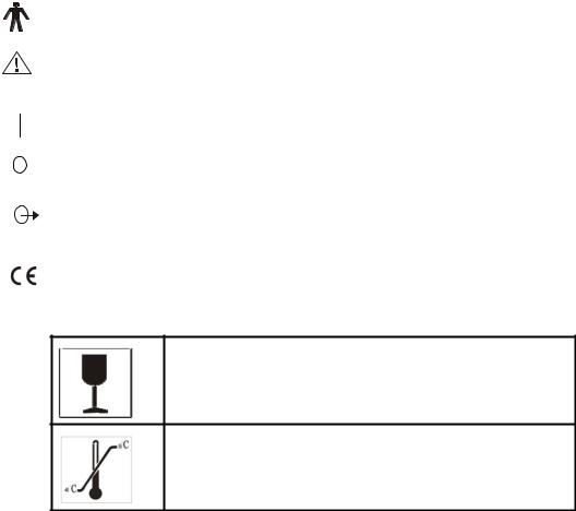
Symbols
Type B device
Attention! Consult accompanying documents
Switch On (general power)
Switch Off (general power)
Signal output
0482 CE mark and code of certification body
Handle with care
Temperature limit
2

Upwards
Limited layers of storage
Keep dry
Keep away from sunlight
1.4 Service Life
The service life of the product is six years. Constant use of the equipment after service life will increase the risk of failure and unpredictable risk.
Warning: Users will assume responsibility of the risks associated with the use of the equipment after recommended service life.
Warning: The disposal of the products should comply with the local regulations. Don’t scrap the product with household refuse.
1.5 Operational Environment
Temperature: +5 to +40
Relative humidity: 30% to 75%
Pressure: 70kPa to 106kPa
1.6 Declaration of Electromagnetic Compatibility
PadScan Z5 in operation will not interfere with the wired, wireless or other electrical equipment. It works properly under specified electromagnetic environment.
3

Warning: Using the PadScan Z5 under strong electromagnetic environment, close to generator, X-ray equipment, dentistry and physiotherapy equipment, broadcasting station or buried cable, etc... will introduce interference signals in the image. This will influence the measurement. Please stop using the equipment at the moment to prevent improper measurement. Use the equipment until the interference of preclusion.
Warning: Sharing power supply with other equipments may produce abnormal image. Eliminate the electromagnetic coupling interference of any equipment by verification.
Warning: Replacing with the substandard spare parts of equipment may cause unpredictable electromagnetic compatibility problems, influencing the location of measurement and causing improper measurement. Only the companies and departments appointed by manufacturer are allowed to replace the spare parts of equipment.
1.7 Declaration of Manufacturer
Users will assume all the risks of modifications for the equipment without the manufacturer’s permission.
Warning: It is prohibited to perform any modifications to the equipment without the manufacturer’s permission.
Warning: Modifications to the equipment must be tested by appointed department of the nation to ensure the safety of using the equipment.
1.8 Contraindications
Do not use the equipment on patients with sores or wounds to prevent cross infection.
This equipment is not suitable for the bladder scan of pregnant women and fetus. Do not use the equipment on patients with ascites.
If you scan a patient with a catheter in his/her bladder or with scars in his/her abdomen, measurement accuracy will be affected.
1.9 Heat and Mechanical Indexes
Heat index: PI0.1
Mechanical index: MI 0.1
4

Chapter Two |
Cautions and Warning |
To ensure safety, please read the |
following instructions before using the equipment. The |
equipment shall only be used by the professionals affirmed or authorized by associated medical institution.
2.1Equipment Checks
1.Make sure all the cables are properly connected.
2.Make sure the equipment is working properly.
3.Keep the equipment away from sunlight and keep dry.
Warning: If the equipment or cable is damaged, it is prohibited to use the equipment.
2.2 Pre scan Checks
Check if the probe is properly connected. Make sure no water, chemicals or other material spattered on the equipment. During using the equipment, pay attention to the main parts of it. If there is strange sound or smell, stop using the equipment right away; do not use the equipment until the authorized engineer solves the problem.
2.3 Operation Instructions
Warning: Do not insert nor pull out the probe while the equipment is power on in order not to damage the machine and probe.
1.During using the equipment, please protect the surface of probe and do not clash. Apply the ultrasound gel on the surface of probe to ensure the probe and body is well contacted.
2.Pay attention to the equipment and patient. If the equipment broke down, turn off the power right away and then unplug the power cord.
3.Patients are prohibited to touch the equipment or other electrical equipment.
4.Do not cover the air vent of the equipment.
2.4 Post scan Checks
1.Turn off the power.
2.Unplug the power cord
3.Clean the equipment and the probe
5
2.5 Conditions to Avoid
The equipment should avoid the following:
1.Splash
2.High humidity
3.Poor draught
4.Direct sunlight
5.Dust
6.Gas with salt or sulfur
7.Chemical medicines or gas
8.Strong vibration and clash
9.Our company takes no responsibility for any risks caused by disassembling, refitting of the equipment.
2.6Notice of Using Probe
1.Do not immerse the probe into any liquid.
2.Do not heat the probe.
3.Do not pull or bend the cable of probe in order not to damage it.
4.Use national standard ultrasound gel. Other substance (for example: oil) will damage the probe and the cable of probe.
5.Keep the probe clean. Use neutral detergent or water to clean the ultrasound gel on the probe.
2.7Handling the Equipment
1.Unplug the power cord
2.Do not drop, vibrate or clash the machine and probe.
2.8In case of Equipment Failure
If equipment is not working properly, turn off the power and unplug the power cord. Contact qualified maintenance staff.
2.9Maintenance of Equipment
2.10Maintain Equipment and Probe Safety
2.11Starting up
Assemble the power adapter firstly. Then connect its AC input plug with power outlet and insert its DC output plug into the DC 13.5V port on the right side of the main unit. If the left indicator
6
light on the main unit turns green, it means the DC 13.5V output voltage of the power adapter is working properly.
When you press the power button on the main unit as the right indicator light on the panel turns green, it enters the Power On interface.
7
Chapter Three |
Device Introduction |
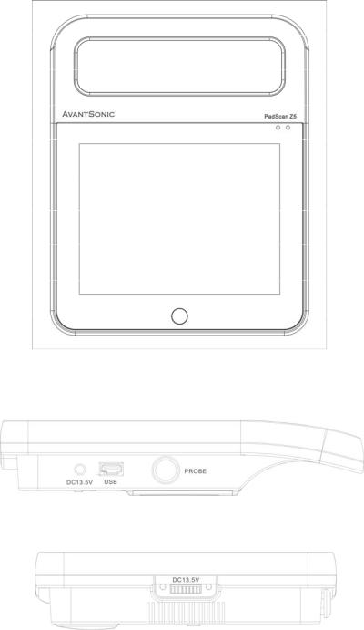
3.1 Figuration
Figure 3 1 PadScan Z5 Front Diagram
Figure 3 2 PadScan Z5 Diagram of Connection Port Side
Figure 3 3 PadScan Z5 Bottom Diagram
8
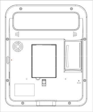
Figure 3 4 PadScan Z5 Back Diagram
3.2Technical Specification
●Probe: 3D mechanical sector
●Standard ultrasonic frequency of operation: 2.5MHz
●Volume measurement range: 0ml 999ml
●Volume measurement accuracy: ±10%
●Volume display resolution: 1ml
●Scan time: 5 seconds
●Ba ery capacity: 2600mA
●Opera on methods: touch screen
●Tissue Harmonic Imaging
●Information storage
●Information print
●Multicolored image display selection ●Multicolored screen style selection
● USB port: connecting PC and user information storage
9
●Bluetooth module: connecting PC by wireless
●Dimension of monitor: 8 inch TFT LCD
●Consumption: 50W
●Dimension of equipment 210*260*50 mm
●Weight: about 1500g (including the probe)
●Power at the state of charging: 30 120VA
●Power supplied by AC when battery is full or by the battery: 30 40VA
●Battery charging time: less than 2 hours
●Battery life: more than 4 hours
10

3.3 Block Diagram
Figure 3 5 PadScan Z5 Principle of Electricity Block Diagram
11
3.4 Basic Principle
The equipment utilizes 3D mechanical sector probe to scan the bladder, and form into multiple 2D ultrasound images on the basis of detected bladder information. After sophisticated image processing, getting the area of multiple bladder sections, projecting 3D imaging, then it measures the bladder volume by sophisticated algorithm.
Operating principle: 1. Transmits the pulse signal to the 3D probe, emit the ultrasound to the human body by the transducer of probe. When the ultrasound passes the tissue plane of human body, it produces reflected wave and scattered wave and locates the tissues and organs according to the return period. And it detects the feature of tissue according to the acoustic intensity. Transmit such pulses can only acquire one signal of one plane, meaning to produce a sectional 2D image it needs to emit ultrasound at least 96 or 128 times to form one section. Then the emitted and received images will be displayed on the screen. Modulate the grey scale of signal intensity of acoustic beam and a sectional plane image will be displayed. The electrical signal will be transmitted to digital scan converter for filtering, detecting and compressing after amplification.
The reflected ultrasound converts the acoustic energy into electric energy. Due to the difference of method and display direction of scan imaging and the difference of imaging speed. There is a digital scan converter in the equipment to switch the emission scan into imaging scan in order to realize 2D sectional real time imaging. A series of imaging processing will be carried out in the digital scan converter then form a sectional image with high definition.
The 3D probe is driven by two electric motors, driving the rotation and swing of crystal at top of the probe. The lower step motor drives 180 degree rotation of the crystal whereas the upper step motor drives 120 degree swing of the crystal. When the lower step motor reaches the edge and become fixed, the upper step motor waggles 120 degree. And we get the first ultrasound image at this moment. Then the lower step motor rotates 15 degree and become fixed. The upper step motor swing 120 degree and we get the second ultrasound image. Then the lower step motor rotate 15 degree and the upper step motor rescan. The lower step motor rotates and upper step motor swings again and again until the lower step motor rotate 180 degree and ends. 13 images are acquired. Then the equipment processes and calculates 12 images of the 13 images, getting the bladder volume.
12
3.5 Equipment Configuration
A main unit
A power adapter AC100 240V±24V 50/60Hz, 1.2A 120VA 13.5VD.C 5A Main unit: DC13.5V±0.5V
A MP2/2.5MHZ 3D mechanical sector probe
A bottle of ultrasound gel
A User Manual
A Li ion battery: model: SNLB 325
A Certificate
A Warranty Certificate
A Packing List
A carrying case
13
Chapter Four |
Device Installation |
4.1 Unpacking
Please make sure there is no shipping damage once you unpack the device. Check all the parts and components in accordance with the Packing List and install it based on the requirements and methods described in "4.2".
4.2 Installation
Check the power adapter and insert its AC input plug into a power outlet after making sure adapter’s power supply is within the stipulated power range.
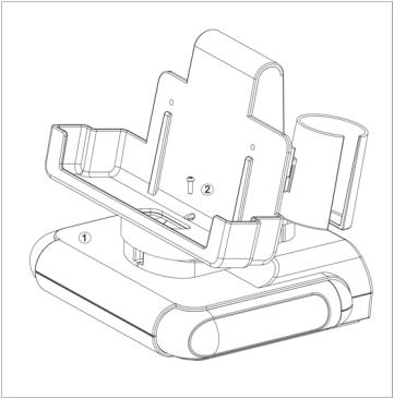
Connect the main unit with the docking station. Align the socket on the bottom of the main unit with the connector of the docking station and then put the main unit onto the docking station.
The installation is proceeded as below: (as figure 4 1) Step 1: put the backrest on the base
Step 2: tighten the screw
14

Figure 4 1 PadScan Z5 Docking Station and Main Unit Connection Diagram Connect the probe to the main unit. Align the red dot on the probe with the red dot on
the back of the main unit (Identifier of Probe), and insert the probe into probe socket on right side of the main unit as figure 4 2.
Lock slot: any notebook security lock is applied to this lock slot as figure 4 2.
Figure 4 2 PadScan Z5 Probe and Main unit Connection Diagram
● Battery installation and removal
Battery installation:
Insert the alignment plate of the battery into the alignment hole of the battery slot, and move the locking key of the battery following the direction of arrow. Insert the battery into the slot slowly. After that move the locking key to the opposite direction of arrow. Show as figure 4 3:
Figure 4 3 PadScan Z5 Battery Installation Diagram
Battery removal Move the locking key of the battery following the direction of arrow, pull out of
the battery at the side seam between the battery and the equipment. Show as figure 4 4.
15
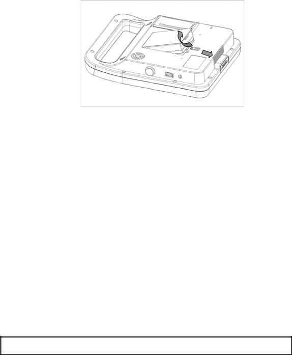
Figure 4 4 PadScan Z5 Battery Removal Diagram
4.3 Power Supply
The device is powered by power adapter and built in battery, both of which are interchangeable.
4.3.1 Power Supply from Power Adapter
1.Check if the adapter is working properly; verify if the EPS is in the specified range. Insert the AC input plug of the adapter into the socket of the power supply. The output voltage of the adapter is DC 13.5V.
2.Connect the DC output plug of the adapter to the DC 13.5V port on the right side of the main unit. If the left indicator light on the main unit turns green, then the DC 13.5V output voltage of adapter is working properly. Press the power button on the main unit and the right indicator light turns green, entering the working status.
Warning: It is prohibited to use the adapter which is not supplied by manufacturer.
4.3.2 Power Supply from Battery
1. Insert the battery into the main unit as described in “4.2”. The power indicator light on the left turns green.
2. Press the power button to turn on the machine. The indicator light on the right turns green. The power is on and the machine enters the working status.
4.3.3 Battery Charging
1. Insert the battery into the main unit
16
 Loading...