


Flush Wood Insert
Owner's Manual
Masonry Fireplace Insert
Save these instructions for future reference
SAFETY NOTICE: If this appliance is not properly installed, a house fire may result. For your safety, follow the installation directions. Contact local building or fire officials about restrictions and installation inspection requirements in your area.
Travis Industries, Inc. |
|
Copyright 2007, Travis |
|
|
Industries, Inc. |
||
4800 Harbour Pointe Blvd SW |
|
||
|
|
|
|
Mukilteo, WA 98275 |
|
$10.00 |
100-01157 |
|
|
||
Listed
4041116 |
Tested to: U.L. 1482 |

2 |
Introduction |
Introduction
We welcome you as a new owner of a Travis Industries Flush Wood wood-burning fireplace insert. In purchasing a Flush Wood you have joined the growing ranks of concerned individuals whose selection of an energy system reflects both a concern for the environment and aesthetics. The Flush Wood is one of the finest appliances the world over. This manual will explain the installation, operation, and maintenance of this appliance. Please familiarize yourself with the Owner's Manual before operating your appliance and save the manual for future reference. Included are helpful hints and suggestions which will make the installation and operation of your new appliance an easier and more enjoyable experience. We offer our continual support and guidance to help you achieve the maximum benefit and enjoyment from your appliance.
Important Information
No other Flush Wood appliance has the same serial number as yours. The serial number is stamped onto the label on the back of the appliance.
This serial number will be needed in case you require service of any type.
Model: |
Flush Wood Insert |
Serial Number:
Purchase Date:
Purchased From:
Register your warranty online at:
traviswarranty.com
Or, mail your warranty card to:
Travis Industries House of Fire
4800 Harbour Pointe Blvd. SW
Mukilteo, WA 98275
Save Your Bill of Sale.
To receive full warranty coverage, you will need to show evidence of the date you purchased your heater. Do not mail your Bill of Sale to us.
We suggest that you attach your Bill of Sale to this page so that you will have all the information you need in one place should the need for service or information occur.
|
|
|
|
|
|
|
|
|
|
|
|
|
|
|
|
|
|
|
|
|
|
|
|
|
|
|
|
|
|
|
|
|
|
|
|
|
|
|
|
|
|
|
|
|
|
|
|
|
|
|
|
|
|
|
|
|
|
|
|
|
|
|
|
|
|
|
|
|
|
|
|
|
|
|
|
|
|
|
|
|
|
|
|
|
|
|
|
|
|
|
|
|
|
|
|
|
|
|
|
|
|
|
|
|
|
|
|
|
|
|
|
|
|
|
|
|
|
|
|
|
|
|
|
|
|
|
|
|
|
|
|
|
|
|
|
|
|
|
|
|
|
|
|
|
|
|
|
|
|
|
|
|
|
|
|
|
|
|
|
|
|
|
|
|
|
|
|
|
|
|
|
|
|
|
|
|
|
|
|
|
|
|
|
|
|
|
|
|
|
|
|
|
|
|
|
|
|
|
|
|
|
|
|
|
|
|
|
|
|
|
|
|
|
|
|
|
|
|
|
|
|
|
|
|
|
|
|
|
|
|
|
|
|
|
|
|
|
|
|
|
|
|
|
|
|
|
|
|
|
|
|
|
|
|
|
|
|
|
|
|
|
|
|
|
|
|
|
|
|
|
|
|
|
|
|
|
|
|
|
|
|
|
|
|
|
|
|
|
|
|
|
|
|
|
|
|
|
|
© Travis Industries |
100-01157 |
|
|
4041116 |
||||||||||||||||||

Table of Contents |
3 |
General Information |
|
Introduction ...................................................... |
2 |
Important Information ......................................... |
2 |
Safety Precautions............................................. |
4 |
Features & Specifications .................................... |
6 |
Fireplace Insert Installation |
|
Planning The Installation ..................................... |
7 |
Preparation for Installation .............................. |
7 |
Packing List ................................................. |
7 |
Additional Accessories Needed for Installation .... |
7 |
Suggested Order of Installation ........................ |
7 |
Installation Considerations .............................. |
8 |
Masonry Fireplace Requirements.......................... |
8 |
Hearth Requirements ......................................... |
8 |
Insert Placement Requirements ............................ |
9 |
Face Dimensions............................................... |
9 |
Drafting Performance ......................................... |
10 |
Leveling Bolt Installation...................................... |
10 |
Flue Installation ................................................. |
10 |
Block-Off Plate Installation................................... |
11 |
Surround Panel Installation .................................. |
12 |
Face Installation ................................................ |
14 |
Re-Routing the Electrical Cord to the Left Side ........ |
15 |
Insert with Positive Connection ............................. |
16 |
Insert with Direct Connection................................ |
16 |
Operating Your Appliance |
|
Safety Notice: ................................................... |
17 |
Before Your First Fire ......................................... |
17 |
Door Operation ................................................. |
18 |
Bypass Operation .............................................. |
19 |
Starting a Fire ................................................... |
19 |
Adjusting the Burn Rate ...................................... |
21 |
Ash Removal .................................................... |
21 |
Blower Operation .............................................. |
22 |
Re-Loading the Stove ......................................... |
22 |
Overnight Burn.................................................. |
22 |
Normal Operating Sounds ................................... |
22 |
Hints for Burning................................................ |
23 |
Selecting Wood ................................................. |
23 |
Troubleshooting ................................................ |
24 |
Maintaining Your Appliance |
|
Daily Maintenance (while stove is in use) ................ |
25 |
Remove Ash (if necessary).............................. |
25 |
Clean the Glass (if necessary) ......................... |
25 |
Monthly Maintenance (while appliance is in use)....... |
26 |
Door and Glass Inspection .............................. |
26 |
Creosote - Formation and Need for Removal ...... |
2 |
Yearly Maintenance............................................ |
27 |
Touch Up Paint ............................................. |
27 |
Cleaning the Air Duct and Blower ..................... |
27 |
Firebrick and Baffle Inspection ......................... |
27 |
Door Parts ........................................................ |
28 |
Replacing the Glass....................................... |
28 |
Replacing the Door Gasket.............................. |
28 |
Replacing the Door Handle.............................. |
28 |
Blower and Electrical Parts .................................. |
29 |
Firebox Parts .................................................... |
29 |
Baffle Parts .................................................. |
29 |
Baffle Removal ............................................. |
29 |
Air Tube Removal & Replacement .................... |
30 |
Brick Removal & Replacement................................. |
31 |
Warranty |
|
Warranty .......................................................... |
32 |
Listing Information |
|
Listing Label ..................................................... |
33 |
Index |
|
Index ............................................................... |
34 |
© Travis Industries |
100-01157 |
4041116 |

4 |
Safety Precautions |
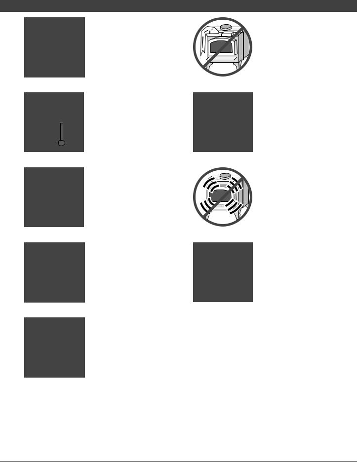
The viewing door must be closed and latched during operation.
Never block free airflow through the air vents on this appliance.
This appliance is designed and approved for the burning of cord wood only. Do not attempt to burn any other type of fuel other than cord wood in this appliance, it will void all warranties and safety listings.
Do not touch the appliance while it is hot and educate all children of the danger of a hightemperature appliance. Young children should be supervised when they are in the same room as the appliance.
This appliance must be properly installed to prevent the possibility of a house fire. The instructions must be strictly adhered to. Do not use makeshift methods or compromise in the installation.
ASHES
36"
Ok
Gasoline or other flammable liquids must never be used to start the fire or "Freshen Up" the fire. Do not store or use gasoline or other flammable liquids in the vicinity of this appliance.
Ashes must be disposed in a metal container with a tight lid and placed on a noncombustible surface well away from the home or structure.
Keep furniture, drapes, curtains, wood, paper, and other combustibles a minimum of 36" away from the front of the appliance.
Contact your local building officials to obtain a permit and information on any installation restrictions or inspection requirements in your area. Notify your insurance company of this appliance as well.
Inspect the chimney connector and chimney at least twice monthly and clean if necessary. Creosote may build up and cause a house fire.
Do not connect this appliance to any chimney serving another appliance.
|
|
This appliance must be |
|
|
|
Type |
|
connected to a listed high |
Clay |
temperature (UL 103 HT) |
|
HT |
Liner |
residential type chimney or an |
|
|
approved masonry chimney with |
|
|
a standard clay tile, or stainless |
|
|
steel liner. |
© Travis Industries |
100-01157 |
4041116 |
Safety Precautions
Never try to repair or replace any part of this appliance unless instructions are given in this manual. All other work must be done by a trained technician.
Allow the appliance to cool before carrying out any maintenance or cleaning.
Maintain the door and glass seal and keep them in good condition.
Avoid placing wood against the glass when loading. Do not slam the door or strike the glass.
Do not throw this manual away. This manual has important operating and maintenance instructions that you will need at a later time. Always follow the instructions in this manual.
Travis Industries, Inc. grants no warranty, implied or stated, for the installation or maintenance of your appliance, and assumes no responsibility of any consequential damage(s).
5
Do not place clothing or other flammable items on or near this appliance
Do not make any changes or modifications to an existing masonry fireplace or chimney to install this appliance.
Do not make any changes to the appliance to increase combustion air.
Overfiring the appliance may cause a house fire. If a unit or chimney connector glows, you are overfiring.
Do not use a grate or other device to elevate the fire off of the firebox floor. Burn the fire directly on the bricks.
© Travis Industries |
100-01157 |
4041116 |

6 |
Features & Specifications |
Installation Options:
•Masonry Fireplace Insert
WARNING: Do not install this fireplace insert into a factory-built metal (Z.C.) fireplace.
Features:
•EPA Phase II Approved
•2.9 Cubic Foot Firebox Volume
•Single Operating Control
•Accepts Logs Up to 24" Long
•Steel Plate Construction (5/16" & 1/4")
•Heavy Duty Refractory Firebrick
•Standard High-Tech Blower
•Five Sided Convection Chamber
Heating Specifications:
Approximate Maximum Heating Capacity (in square feet)* |
1,200 to 2,000 |
Maximum BTU's per Hour (Cord Wood Calculation) |
73,300 |
Overall Efficiency (Oregon Method) |
71.1 % |
Maximum Burn Time |
Up to 12 Hours |
* Heating capacity will vary depending on the home's floor plan, degree of insulation, and the outside temperature. It is also affected by the quality and moisture level of the fuel.
Dimensions:
6" Diameter Flue Vent
NOTE:
Clearances are measured from the base of the fireplace insert.
Weight 450 Lbs.
28-7/8"
5-5/8"
21-1/4"
21-1/2"
11-1/8"
Electrical Line 20-1/2" (may be re-routed
to opposite side)
1-1/4” |
Fireplace Opening |
|
Figure 1
Emissions:
4.1 Grams Per Hour (EPA Phase II Approved)
© Travis Industries |
100-01157 |
4041116 |

Installation (for qualified installers only) |
7 |
SAFETY NOTICE:
Please read this entire manual before you install and use yournew roomheater. Failure to follow instructions may result in property damage, bodily injury, oreven death. Contact local building orfire officials about restrictions and installation inspection requirements in yourarea.
Planning The Installation
We suggest that you have an authorized Travis Industries dealer install your fireplace insert. If you install the fireplace insert yourself, your authorized dealer should review your installation plans.
Check with local building officials for any permits required for installation of this fireplace insert and notify your insurance company before proceeding with installation.
Preparation for Installation
•Check for damage to the exterior of the fireplace insert (dents should be reported, scratches can be fixed by applying touch up paint).
•Check the interior of the firebox (replace cracked firebrick and make sure baffle is in place).
The fireplace insert can be lightened by removing the firebricks and baffle (pg 29) - replace before operation.
Packing List
•Touch-Up Paint
•Leveling Bolts
•(3) Chimney Brackets with (6) Tek Self-drilling screws (for attaching the flue to the fireplace insert)
•(6) 10-24 x 1/2" Type F Screws (for surround panels)
•(7) Spring Clips (for surround panels)
•Rheostat (for blower)
•Pull Tool for Bypass
Additional Accessories Needed for Installation
1 Face (see your dealer for details - see pg 14)
2Surround Panels (see page 12)
Suggested Order of Installation
1Remove the firebrick and baffle components from the fireplace insert (see pages 29 and 31).
2Place the fireplace on the hearth 12" from the fireplace (on top of cardboard to prevent scratching). If power is on the left side, switch the power cord at this time (see page 15).
3Install the side suround panels (see page 12).
4Slide the insert into place (it should portrude 1-1/4" from the fireplace opening).
5Hook up the flue (with the baffle components removed - this allows for access from within the firebox).
6 Install the top panel and trim. Then replace the firebrick and baffle components.
7 Install the face (see page 14).
© Travis Industries |
100-01157 |
4041116 |
8 |
Installation (for qualified installers only) |
Installation Considerations
NOTE: Face Seal Connections are not allowed with this fireplace insert.
Installation Type |
Considerations |
|
|
|
|
Insert with Positive Flue (Full Reline) |
• Provides best draft |
|
(Page 16) |
• Easiest to clean |
|
• Easiest to install |
||
|
||
Insert with Direct Connect Flue |
• Provides good draft |
|
(Page 16) |
• Requires fireplace block-off plate - see page 11 |
|
|
||
|
|
Masonry Fireplace Requirements
•Chimney must have a clay tile liner or a stainless steel liner (positive connection)
•Entire fireplace, including chimney, must be clean and undamaged. Any damage must be repaired prior to installation of the insert
•Chimney height: 15' minimum; 33' maximum.
•Entire fireplace, including chimney, must meet local building requirements
•Figure 2 shows the minimum size requirements for the type of fireplace used.
j
i
Combustible |
Mantel |
||
|
|
|
|
Non- |
|
h |
|
Combustible |
Facing |
||
b |
|
|
|
a |
|
|
|
|
|
|
d |
Non |
c |
e |
|
|
|
||
|
|
|
|
- |
|
|
|
Combustible |
|
|
|
g |
|
Hearth |
|
|
|
||
f
Minimum Fireplace Size |
Masonry |
||
Fireplace |
|||
|
|
||
a |
Height (front) |
21-1/2" |
|
b |
Height (rear) |
21-1/2" |
|
c |
Width (front)* |
30-7/8" |
|
d |
Width (rear) |
21-1/4" |
|
e |
Depth |
20-1/2" |
|
f |
Hearth Depth |
17-1/4" |
|
g |
Hearth Width |
44-7/8" |
|
h |
Facing Width |
46-7/8" |
|
i |
Facing Height |
39" |
|
j |
Mantel Height |
41-1/2" |
|
* Includes 2" for power cord.
Figure 2
Hearth Requirements
•The fireplace insert must be placed on the masonry hearth built to UBC standards.
•The non-combustible extension in front of the insert must extend 16" in front of the insert and 8" to both sides.
© Travis Industries |
100-01157 |
4041116 |

Installation (for qualified installers only) |
9 |
Insert Placement Requirements
•The insert must be placed so that no combustibles are within, or can swing within (e.g. drapes, doors), 36" of the front of the insert
•Insert and hearth must be installed on a level, secure floor
•The minimum clearances, facing, and hearth requirements in Figure 3 must be met.
Side
Wall
k
l
p
|
Combustible |
Mantel |
|
|
|
|
|
|
|
n |
Combustible |
Top |
|
|
|
|
Facing |
||
|
|
|
||
|
|
|
|
|
m |
Facing |
|
Minimum Clearances
k |
Sidewall to Insert |
9" |
l |
Side Facing |
9" |
m |
Top Facing* |
39" |
n |
Mantel to Insert* |
41-1/2" |
o |
Hearth (Front) |
16" |
p |
Hearth (Side) |
8" |
q |
Front of Insert |
36" |
x |
Extension onto Hearth |
1-1/4" |
q
Non-
HearthCombustible
|
x |
* Measure from the base of the |
|
|
|
o |
|
fireplace insert. |
Figure 3
Face Dimensions
Avalon Victorian Lace |
Fireplace Xtrordinair Arched |
Lopi Wilmington |
33” |
33-3/8” |
33-1/2” |
|
 2-7/8”
51-1/2” Radius
23-1/4” |
23-7/8” |
23-1/4” |
Figure 4
© Travis Industries |
100-01157 |
4041116 |

10 |
Installation (for qualified installers only) |
Drafting Performance
This appliance relies upon natural draft to operate. External forces, such as wind, barometric pressure, topography, or factors of the home (negative pressure from exhaust fans, chimneys, air infiltration, etc.), may adversely affect draft. Travis Industries can not be responsible for external forces leading to less than optimal performance.
Leveling Bolt Installation
Two leveling bolts are included to level the insert if the fireplace has a stepped-up hearth. To install, raise the rear of the insert up and insert the leveling bolts into the holes in the rear corners of the insert. Adjust the bolts until they extend the same height as the hearth steps up. After the insert is installed, fine-tune the leveling bolts to level the insert (see Figure 5).
The leveling bolts
go into the holes
at the rear corners
of the insert.
The leveling bolts should stick out this far from the base of the insert.
Fireplace |
Hearth |
Figure 5
Flue Installation
Flue (flexible or rigid)
Included in the owner’s pack are three “flue brackets” and six self-
drilling screws. Use these
Flue Bracket
components to secure the flue to the fireplace insert.
Self-Drilling Screws
Flue Opening
Figure 6
© Travis Industries |
100-01157 |
4041116 |
Installation (for qualified installers only) |
11 |
Block-Off Plate Installation
Whenever this appliance is installed with a direct connection a block-off plate, or other non-combustible seal-off device (e.g. damper adapter), will need to be installed. This device is used to seal the chimney, insuring no smoke enters the home and providing the chimney system with a seal to promote draft. The directions below detail the steps for construction and installation of a block-off plate.
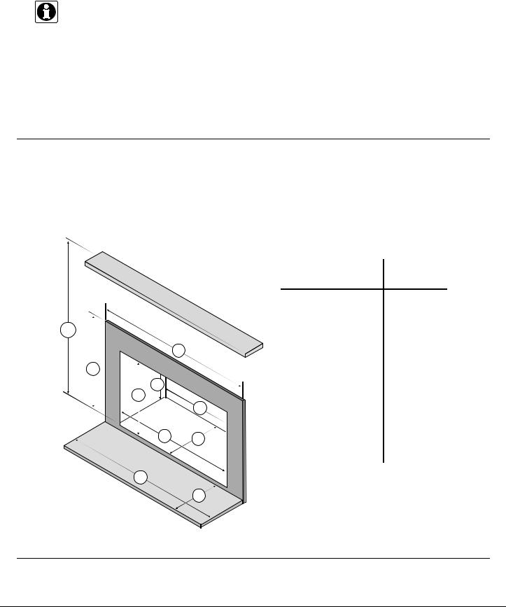
1.Determine a location for the block-off plate at the top of the firebox below the damper area (make it high enough to allow installation of the connection pipe). The location should be level and in an area where it can be mounted easily. Measure the width at the rear ("A") and front ("B") of the firebox at the height where the block-off plate will be installed (see Figure 7). Then measure the depth of the location where the block-off plate will be installed ("C").
2.Make a cardboard template of the measurements, but add a 2" flange to each side. This flange will be used to mount the block-off plate to the inside of the firebox. Bend the flanges downwards on the template and place it inside the fireplace. If the template fits correctly in its planned location, go to the next step. If it does not, make a new template with the appropriate corrections until it fits correctly.
3.With the template in place, mark the location of the flue (see “Dimensions” on page 6). This location approximates the center of the flue when the insert is in place (a slight offset may occur based upon insert and block-off plate placement). Remove the template and cut a 6 1/4" diameter hole centered on this mark.
4.Make the block-off plate of 24 gage or thicker steel to match the template. Drill two holes in each flange for mounting the plate.
5.Mount the block-off plate using masonry screws.
6.Insulate the block-off plate using high-temperature fiberglass insulation (Kaowool® or equivalent) and furnace cement (allow the cement to dry for at least 24 hours before burning).
7.After placing the appliance and installing the pipe through the block-off plate, use high-temperature fiberglass insulation and furnace cement to seal any cracks between the pipe and block-off plate.
|
|
|
Block-Off Plate Template |
|
|
|
|
2" Flanges |
Measurement |
|
|
Damper |
(for attaching |
"A" |
|
|
|
|
|
|
|
|
the block-off |
|
|
|
|
plate) |
|
|
|
|
|
Measurement |
|
|
|
|
"C" |
See the |
B |
|
|
|
dimensions to |
|
|
|
|
|
|
|
|
|
determine the |
C |
A |
|
|
location of the |
|
Measurement "B" |
||
|
|
|
||
center of the |
|
|
|
|
Firebox |
|
|
||
|
|
|
||
flue. |
|
|
See the dimensions to determine the location of |
|
|
|
|
||
|
|
|
the center of the flue. |
|
Figure 7
© Travis Industries |
100-01157 |
4041116 |
 Loading...