

Page 1

ZC Kit – Large Pellet Insert
(99200149)
Compatibility
• Astoria Bay Pellet Insert
• Yankee Bay Pellet Insert
Packing List
• ZC Can Rear Panel
• ZC Can Top/Side Panel
• ZC Can Rear Vent Shield
• (26) # 8 x 3/8” Type A Screws
Overview
This kit allows an installer to build the above pellet heaters into the framing of a home.
Installation Overview
The minimum framing dimensions and clearances listed in this instruction sheet must be maintained.
Failure to follow all of the instructions in this instruction sheet, and in the manual, will void the listing and
warranty of the pellet heater, and may create a serious fire hazard.
This kit is approved for use in a mobile home.
1 Determine the vent configuration (see “Vent Requirements” and “Vent Termination Requirements”)
2 Prepare the enclosure (see “Minimum Enclosure Dimensions”).
3 Install the floor protection and hearth (see “Minimum Floor Protection”).
If venting to the rear (most common)
Place the 90° onto the insert starter collar and measure the height of the center of the vent. This will
determine the center height of the wall thimble installed behind the insert in the wall. NOTE: The vent is
located 7.5” left of center of the appliance. Install the thimble into the wall, making sure the 3” clearance to
combustibles is met (refer the directions included with the thimble for additional details). Remove the starter
collar from the pellet heater and install it onto the elbow (seal with silicone). Determine the correct length for
the horizontal section of vent (the center of the starter collar is 11.25” behind the enclosure opening) and
attach it to the elbow (seal with silicone). Place this flue section aside until after the zc can is installed. Then
insert the flue section through the can and thimble. Once the insert is in place, attach the starter section to
the insert (it is attached with a latch – make sure the gasket is correctly positioned). Attach the additional vent
components to finalize the vent installation (termination, elbow, etc.).
If venting upwards
When installing with vertical vent, the area above the insert must be accessible after the zc can and insert
have been installed (note: the vent is located 11.25” behind the enclosure opening, 7.5” left of center).
Remove the starter collar from the pellet heater and install it onto the vent (seal with silicone). Insert this vent
through the zc can and attach the starter section to the insert (it is attached with a latch – make sure the
gasket is correctly positioned). Attach the additional vent components to finalize the vent installation
(additional vent lengths, elbows, terminations, etc.).
3 Construct and Install the ZC Can (see “ZC Can Construction and Placement”)
4 Prepare the insert in place it into the ZC Can (see “Insert Preparation and Placement”)
Page 1 of 8 10/9/06 © Travis Industries, Inc.
Page 2

ZC Kit – Large Pellet Insert
(99200149)
Vent Requirements
• Must be 4" diameter Type "L" (except for masonry fireplace installations) - or - connect the vent to a
factory built type "A" chimney. All vent joints (including adapters, elbows, etc…) must be sealed with 500°
F. RTV silicone.
• Pellet vent must maintain a minimum 3" clearance to any combustible (install vent at clearances specified
by the vent manufacturer).
• Do not connect the pellet vent to a vent serving any other appliance or stove.
• The maximum venting distance is
shown in the illustration to the right.
• Do not install a flue damper in the
exhaust venting system of this unit.
33 Feet
(max.)
30 Feet
• Use an approved wall thimble when
passing the vent through walls and a
ceiling support/fire stop spacer when
passing the vent through ceilings
(make sure to maintain 3" clearance to
any combustibles.
• No more than 180° of elbows (two 90°
elbows, one 90° and two 45° elbows,
etc.).
• Pellet vent connections must be
sealed airtight with 500° F. RTV
silicone and screwed together with at
least three sheet metal screws.
Seal each vent section (including
adapters, elbows, etc...) by
500° F. RTV
Silicone
injecting a liberal amount of 500°
F. RTV silicone into the gap
between sections.
• Vent must have a support bracket
every 5' of pellet vent when exterior of
structure
The vent height and run
must not exceed the
distance shown in the
shaded region shown to the
right.
Venting into this shaded
area may require restrictor
adjustments. See the
section “Restrictor
Adjustment” for details.
NOTE: To achieve optimum
performance, we
recommend keeping the
vent as short as possible
(horizontal run especially).
25 Feet
20 Feet
15 Feet
10 Feet
5 Feet
0 Feet
• Horizontal sections must have a 1/4"
rise every 12" of travel.
0 Feet
5 Feet
10 Feet
(max.)
Page 2 of 8 10/9/06 © Travis Industries, Inc.
Page 3

ZC Kit – Large Pellet Insert
(99200149)
Vent Termination Requirements (See the illustration below)
• Must have an approved cap (to prevent water from entering) or a 45° downturn.
• If the termination is located on a windy side of the house, an approved house shield is
recommended to prevent soot from building up on the side of the house.
• Must not be located where it will become plugged by snow or other material.
• Horizontal terminations must protrude 12" from the wall, vertical terminations require 24".
X
A
B
C
NOTE: Measure clearances to the nearest edge of the exhaust hood.
A Minimum 4' clearance below or beside any door or window that opens
B Minimum 1' clearance above any door or window that opens
C Minimum 2' clearance from any adjacent building
D Minimum 7' clearance above any grade when adjacent to public walkways
NOTE: Vent may not terminate in covered walkway or breezeway.
E Minimum 2' clearance above any grass, plants, or other combustible materials
F Minimum 3' clearance from any forced air intake of any other appliance
G Minimum 2' clearance below eaves or overhangs
H Minimum 1' clearance horizontally from combustible wall
X Must be a minimum of 2' above the roof
H
A
F
E
G
F
D
Page 3 of 8 10/9/06 © Travis Industries, Inc.
Page 4
ZC Kit – Large Pellet Insert
(99200149)
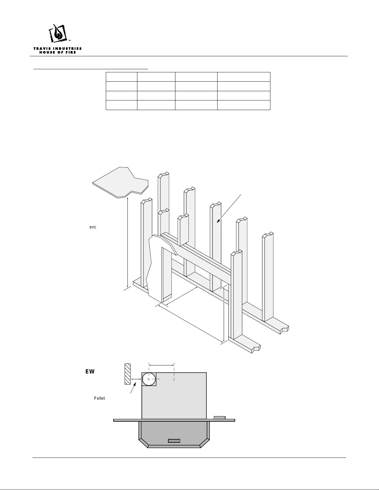
Minimum Enclosure Dimensions
Min. Max. Recommended
Height* 29” 31” ** 30”
Width 36” 43” ** 40”
Depth*** 18” 22” **** 20”
* The enclosure height must be raised the same amount as the floor protection (e.g. if you are using 1” floor
protection, the min. height is 30” above the sub-floor).
** The maximum height is determined by the surround panel size (the surround panels are 32” tall).
*** When determining depth, include the facing material (drywall, tile, etc.) – see the illustration below.
**** When venting vertically, there is no maximum depth.
When determining the position of the insert, consider
Ceiling
the position of the framing behind the insert relative to
the vent - see the illustration below.
NOTE: The enclosure may be
raised. The minimum
distance from the base of the
enclosure to the ceiling is 72”
TOP VIEW
Pellet vent requires 3”
clearance to combustibles.
Depth*
Height
Width
* When determining the depth, include
the facing material (drywall, tile, etc.).
7.5”
Page 4 of 8 10/9/06 © Travis Industries, Inc.
Page 5
ZC Kit – Large Pellet Insert
(99200149)
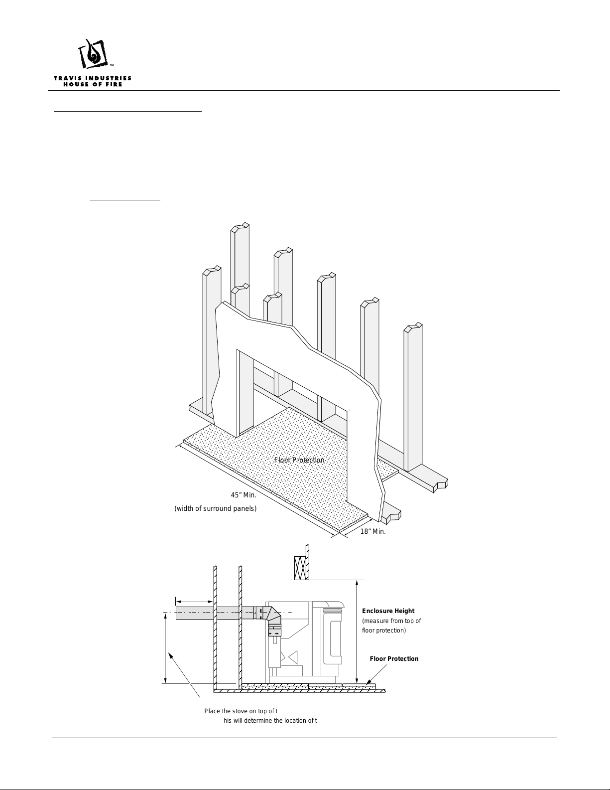
Minimum Floor Protection
• The insert must be placed on a non-combustible floor protector (cement board, sheet metal, etc.) a
minimum .018” thick (26 gauge). This floor protection must extend the full width and depth of the
enclosure and must protrude 6” in front of the door opening (1
width of the surround panels (45” min. width).
• HEARTH NOTE: If you wish to install a hearth greater than 1/2” thick, you will need to raise the insert and
enclosure height the equivalent amount. The leveling bolts may be used on the insert for adjustments.
8” from the enclosure opening) and the full
Floor Protection
45” Min.
(width of surround panels)
18” Min.
12”
Minimum
Enclosure Height
(measure from top of
floor protection)
Floor Protection
Rear Vent Installations
Place the stove on top of the floor protection and measure the center of the
flue. This will determine the location of the wall thimble.
Page 5 of 8 10/9/06 © Travis Industries, Inc.
Page 6
ZC Kit – Large Pellet Insert
A
A
A
(99200149)
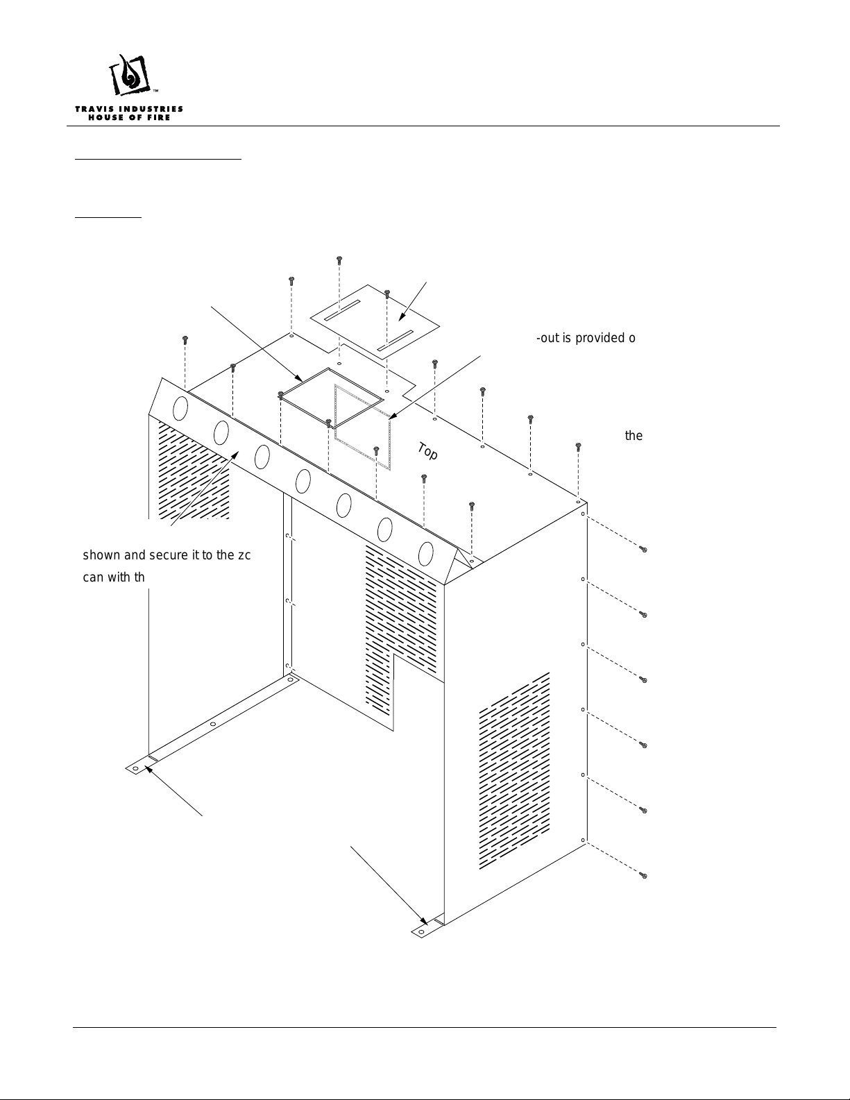
ZC Can Construction
Construct the zc can as shown below.
WARNING: The sheet metal edges are sharp. Use gloves when handling the zc can.
Knock-out for top
vent applications
Bend the top stand-off as
AAAAA
shown and secure it to the zc
can with the included screws.
Rear Vent Shield (not required for top-vent applications)
A knock-out is provided on the rear panel
for rear vent applications.
Top of ZC Can
Use the included screws to
secure the zc can sides and
top to the zc can rear panel.
Bend the mounting flange as shown.
Page 6 of 8 10/9/06 © Travis Industries, Inc.
Page 7
ZC Kit – Large Pellet Insert
(99200149)
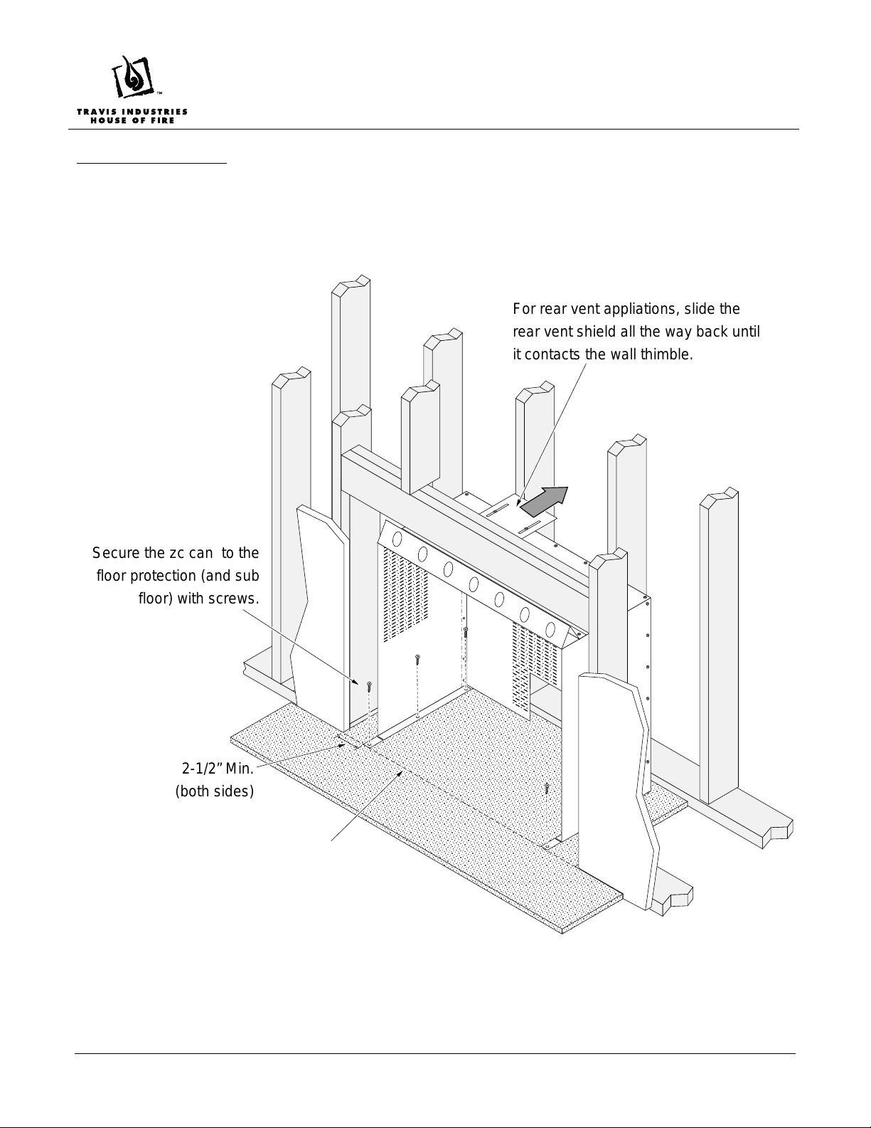
ZC Can Placement
• Place the zc can inside the enclosure. The zc can must be placed so the front edge of the mounting flanges
are flush with the enclosure opening. Secure the enclosure to the floor protection (and sub-floor) with screws.
• When venting horizontally the rear vent shield must be installed over the top of the zc can. When installed,
the rear vent shield should contact the thimble (it acts as a heat shield above the vent.
For rear vent appliations, slide the
rear vent shield all the way back until
it contacts the wall thimble.
Secure the zc can to the
floor protection (and sub
floor) with screws.
2-1/2” Min.
(both sides)
When in place these tabs
must be flush with the
enclosure opening.
Floor Protection
Page 7 of 8 10/9/06 © Travis Industries, Inc.
Page 8
ZC Kit – Large Pellet Insert
(99200149)
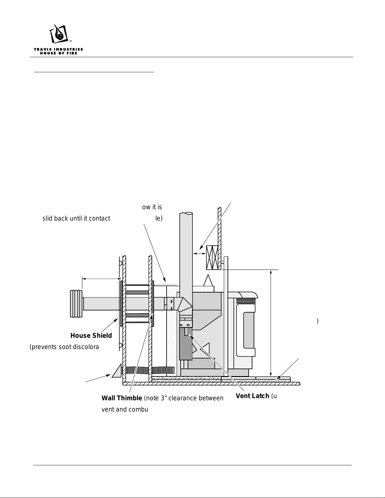
Insert Preparation and Placement
• Place the extending hopper into its highest position (see the manual for details). This increases the pellet
capacity of the heater.
• Install the surround panels onto the insert and slide it into place. The surround panels must maintain a
3/8” gap from the enclosure opening (the stand-offs on the surround panels provide the 3/8” spacing).
• After the insert is in place, attach the vent starter section to the insert (it is attached with a latch – make
sure the gasket is correctly positioned).
• The leveling bolts may be used to level the insert.
• We recommend the use of the Insert Wiring Kit when installing this kit (SKU 97200315). This kit allows
for the power cord to be hard-wired behind the walls, eliminating the need for a visible power cord.
Rear Vent Shield (used only on inserts
venting directly to the rear - note how it is
slid back until it contacts the wall thimble)
12”
Minimum
House Shield
(prevents soot discoloration)
HIGHLY RECOMMENDED
Vent Clearances (make sure
all vent maintains 3” clearance
to any combustible)
Enclosure Height
(measure from top of
floor protection)
Floor Protection
Outside Air
Connection
(recommended)
Page 8 of 8 10/9/06 © Travis Industries, Inc.
Wall Thimble (note 3” clearance between
vent and combustibles)
Vent Latch (used to connect and
disconnect the vent )
 Loading...