

Page 1
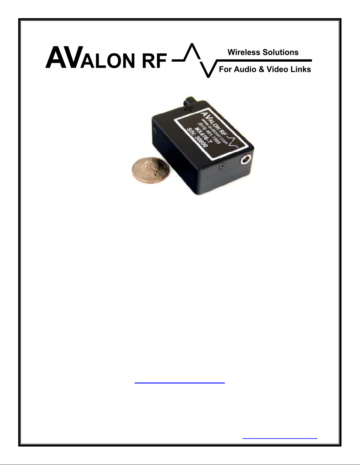
MX416
Wireless Digital Microphone
User's Guide & Operating Manual
REV. X0 25 June 25, 2007
http://www.avalonrf.com/
Avalon RF, Inc. • 344 Coogan Way • El Cajon, CA 92020
Phone: (619) 401-1969 • Fax: (619) 401-1971 • Email: sales@avalonrf.com
Page 2

AVALON RF, INC. Page ii
MX416 User’s Guide & Operating Manual
Table of Contents
1. General................................................................................................1
Figure A – MX416 Controls and Connectors........................................2
Charging Port ......................................................................................3
RF Output/Antenna Connector.............................................................3
I/O Connector......................................................................................3
RF Input/ Antenna Connector..............................................................3
2. Specifications.......................................................................................4
User Interface......................................................................................4
Setup...................................................................................................4
Electrical Interface...............................................................................4
Interconnecting....................................................................................5
Figure B – Battery Charger Connections .............................................5
Figure C – I/O Interface .......................................................................6
Mechanical ..........................................................................................7
Mounting..........................................................................................7
Mechanical Data ..............................................................................8
Figure D – MX416 Mechanical Outline.................................................8
Environmental Conditions....................................................................9
3. Operating the transceiver...................................................................10
4. Ordering information..........................................................................11
Base models......................................................................................11
Options..............................................................................................12
Recommended Accessories..............................................................12
Page 3

AVALON RF, INC. Page 1
MX416 User’s Guide & Operating Manual
1. General
The MX416 rugged digital microphone is intended for use in short
range wireless audio transmission applications for police, homeland
security etc. The RF output power is approx. 250mW and typical lineof-sight operating range is over 3 miles (depends on various factors).
The MX416 works as a pair. The transmitter is very small and
completely self-contained with a microphone and a Li-Ion battery
built-in. The battery is capable of running the MX416 continuously for
over 7 hours. The receiver is powered by an external dc supply and
has a output for driving a 16 ohm headset speaker.
The MX416 offers the following features:
• A secure digital audio link with very short delay.
• UHF frequencies that provide better radio signal penetration
through walls and obstacles
• Low Power and light weight
Page 4
AVALON RF, INC. Page 2
MX416 User’s Guide & Operating Manual
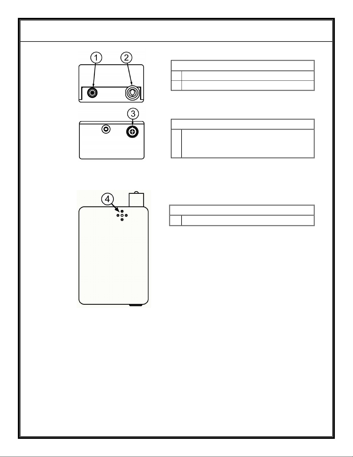
Top View
1 Antenna – MCX Connector
2 Power On/Off switch
Bottom View
3 Transmitter - Battery Charger
Connector
Receiver - I/O Connector
Front View
4 Microphone (Transmitter only)
Figure A – MX416 Controls and Connectors
Page 5

AVALON RF, INC. Page 3
MX416 User’s Guide & Operating Manual
MX416-T (Transmitter)
1.1 Charging Port
The charging connector is a 4-pin size 00B LEMO connector. A
separate wall mount charger is provided thereby avoiding the need
for a cradle.
1.2 RF Output/ Antenna
The MX416 has a 50 Ohm RF output through a MCX jack. An
antenna is included for each unit.
MX416-R (Receiver)
1.3 I/O Connector
This is also a 4-pin size 00B LEMO connector. It has 2 pins for power
and speaker/audio output.
1.4 RF Input/ Antenna
This MCX jack is an rf input connector for an antenna. A short omni
whip (supplied) can be used for short distances up to a few hundred
feet or a high gain omni (or directional antenna if the application
permits) can be connected using a adaptor cable (optional).
Page 6

AVALON RF, INC. Page 4
MX416 User’s Guide & Operating Manual
2. Specifications
2.1 User Interface - On/Off Switch.
The MX416 has an on/off switch. This shuts off power to the entire
transmitter/ receiver.
2.2 Setup.
Since the MX416 works as a pair, it is shipped with a sticker
indicating the operating frequency e.g- 650 MHz. If you have ordered
multiple sets, please ensure the correct pair is used. The user has to
connect the antennas, power & audio cables & the link is ready to
work. There is no specific setup procedure.
2.3 Electrical Interface.
The transmitter has the following interfaces:
2.3.1 Charger Input
a) The charger input is actually a battery charger connection. The
external wall mount battery charger is connected to this jack.
b) This input is switched and protected against reverse polarity.
c) Charging is performed in the power “off” position.
2.3.2 Microphone
a) The MX416 uses an electret microphone and is built into the case.
b) For volume orders, provision for connection of an external
microphone can be made.
2.3.3 RF output to antenna.
a) The RF output connector is a 50
b) The RF output power is approx. 250 mW (transmit).
ΩΩΩΩ
(ohm) MCX receptacle.
Page 7

AVALON RF, INC. Page 5
MX416 User’s Guide & Operating Manual
The receiver has the following interfaces:
2.3.4 Power Input
a) The receiver works on unregulated dc power of 6 – 14 V DC.
Current consumption is only 150 mA.
2.3.5 Speaker Output
a) The MX416 receiver is capable of supplying 30mW into a 16 ohm
headset speaker.
b) If an external amplifier will be used, the speaker/audio signal
should be terminated by a parallel combination of a 22 ohm
resistor and a 0.1uF capacitor. If you need assistance with this
arrangement, please call Avalon RF Engineering and we will
gladly help.
2.4 Interconnecting.
The interface to the transmitter is:
Pin
Function
Number
1 Power/Charge Return (-)
2 N/C (No Connection)
3 N/C (No Connection)
4 Power/Charger Input (+)
Figure B – Battery Charger Input
Page 8

AVALON RF, INC. Page 6
MX416 User’s Guide & Operating Manual
The receiver interface is:
Pin
Function
Number
1 Power/Signal Return (-)
2 Speaker/ Audio output
3 N/C (No Connection)
4 Power Input (+)
Figure C – I/O Interface
Page 9

AVALON RF, INC. Page 7
MX416 User’s Guide & Operating Manual
2.5 Mechanical
2.5.1 Mounting.
Mounting can be done in one of the following methods:
a) Clamping.
Clamping (or hard mounting) is the recommended method and the
only method of mounting in all fixed installations or when operating
from >10V.
Clamping is also the preferred method of mounting in mobile
installations where most electrical interfaces are used.
b) Velcro® to a flat surface.
The MX416 may be mounted using Velcro® if it is required to be
detached frequently. However, in this case it must be operated
from a 9V battery.
Page 10

AVALON RF, INC. Page 8
MX416 User’s Guide & Operating Manual
2.5.2 Mechanical Data.
a) Size 2.37” x 1.68” x 0.97 (see Figure D)
60mm x 43mm x 25mm
b) Weight <5.6 oz.
<158 gram
c) Shipping weight <32 oz.
<900 gram
Figure D – MX416 Mechanical Outline
Page 11

AVALON RF, INC. Page 9
MX416 User’s Guide & Operating Manual
2.6 Environmental Conditions.
The RT423 is designed to meet the following environmental
conditions:
2.6.1 Operating temperature -4° to 122° F
-20° to 50° C
2.6.2 Storage temperature -13° to 150° F
-25° to 65° C
2.6.3 Vibration 1.5G, from 10Hz to 2KHz, sine wave, 3 axis
2.6.4 Shock 15G, 25msec, half sine wave, three axis
2.6.5 Humidity 5 to 95%, non-condensing
2.6.6 Inclination Any
2.6.7 Altitude -1500 feet to 15,000 feet
-450 meter to 4,500 meters
Page 12

AVALON RF, INC. Page 10
MX416 User’s Guide & Operating Manual
3. Operating the transceiver.
Before applying power, make sure all connectors and all antennas
are properly connected.
NOTE
The transmitter will not transmit unless it has an antenna.
The transmitter has only 1 operator control (the on/off switch) and no
indicators (to allow for covert applications). The receiver also has the
same control and no indicators.
This product was primarily designed for covert/ secure
communication applications and therefore may seem to be lacking
some features. For OEM applications, please contact Avalon RF with
your requirements.
Follow the guidelines below to optimize the operating distance/range:
a) The transmit antenna’s location is vital to a radio link. Keep the
transmit antenna completely clear of any metal object or carbon
composite materials. If the transmitter is placed on a person’s
body, the transmit antenna should be placed to clear the body,
particularly the head.
b) To get the optimum range, the transmit antenna should be located
as high above the ground as the application permits.
c) The receive antenna should be generally in view of the transmit
antennas radiation pattern. If you have any doubts or concerns,
please call Avalon RF Engineering at (619) 401-1967.
d) Do not place the antennas in the vicinity of other antennas even
though they may be on different bands.
Page 13

AVALON RF, INC. Page 11
MX416 User’s Guide & Operating Manual
4. Ordering information
4.1 Base model.
MX416
The user may order this set with a allocated frequency by specifically
requesting it or the unit will be shipped with a frequency in the ISM
band.
All units come with the following standard accessories:
4.1.1 Omni directional ¼ wavelength whip antenna
4.1.2 A wall mount battery charger for the transmitter and a 3 ft cable with
flying leads for the power and audio output.
4.1.3 User guide & operating manual (this manual).
Page 14

AVALON RF, INC. Page 12
MX416 User’s Guide & Operating Manual
4.2 Options.
4.2.1 T.B.D
4.3 Recommended accessories.
4.3.1 Antennas
a) AX402 – 2 dBi Half Wave Omni antenna for mounting on external
equipment (also improves range)
b) AX410LP - 10 dBi UHF Log Periodic antenna for receive/ transmit
for fixed installation or if the direction of the mobile unit will be known.
4.3.2 Cables
T.B.D.
4.3.3 Battery packs
a) BAT80 – 14.4V/80WH Li-Ion battery pack with charger and power
cable to transceiver. It will run an MX416-T (transmitter) for 16
hours.
b) BAT92 – 14.4V/92WH Li-Ion battery pack with charger and power
cable to transceiver. It will run an MX416-T for 20 hours.
 Loading...