

Page 1

49660-00B
MegaRAID® SAS 9260CV-4i and SAS
9260CV-8i RAID Controllers
Quick Installation Guide
49660-00, Revision B
July 2011
Page 2

Revision History
Version and Date Description of Changes
49660-00 Rev. B, July 2011 Second release of document.
49660-00 Rev. A, December 2010 Initial release of document.
LSI and the LSI logo are trademarks or registered trademarks of LSI Corporation or its subsidiaries. All other brand and product names may be trademarks of their respective companies.
LSI Corporation reserves the right to make changes to the product(s) or information disclosed herein at any time without notice. LSI Corporation does not assume any responsibility or liability arising
out of the application or use of any product or service described herein, except as expressly agreed to in writing by LSI Corporation; nor does the purchase, lease, or use of a pr oduct or service from
LSI Corporation convey a license under any patent rights, copyrights, trademark rights, or any other of the intellectual property rights of LSI Corporation or of third parties.
This document contains proprietary information of LSI Corporation. The information contained herein is not to be used by or disclosed to third parties without the express written permission of LSI
Corporation.
Corporate Headquarters Email Website
Milpitas, CA globalsupport@lsi.com www.lsi.com
800-372-2447
Document Number: 49660-00 Revision B
Copyright © 2011 LSI Corporation
All Rights Reserved
Page 3
MegaRAID SAS 9260CV-4i and SAS 9260CV-8i RAID Controller Quick Installation Guide
Quick Installation Guide
MegaRAID SAS 9260CV-4i RAID Controller and SAS 9260CV-8i RAID Controller
Thank you for purchasing the LSI™ MegaRAID® 6Gb/s SAS 9260CV-4i RAID controller or
the LSI MegaRAID
provides reliability, high performance, and fault-tolerant drive subsystem
management.
Before you install your RAID controller, please take a few minutes to read this quick
installation guide. This guide documents how to install the RAID controller and connect
the CacheVault Flash Module (CVFM01)to the remote CacheVault Power Module
(CVPM01). If you need more information about any topic covered in this guide, refer to
the related documents on your MegaRAID Universal Software Suite CD.
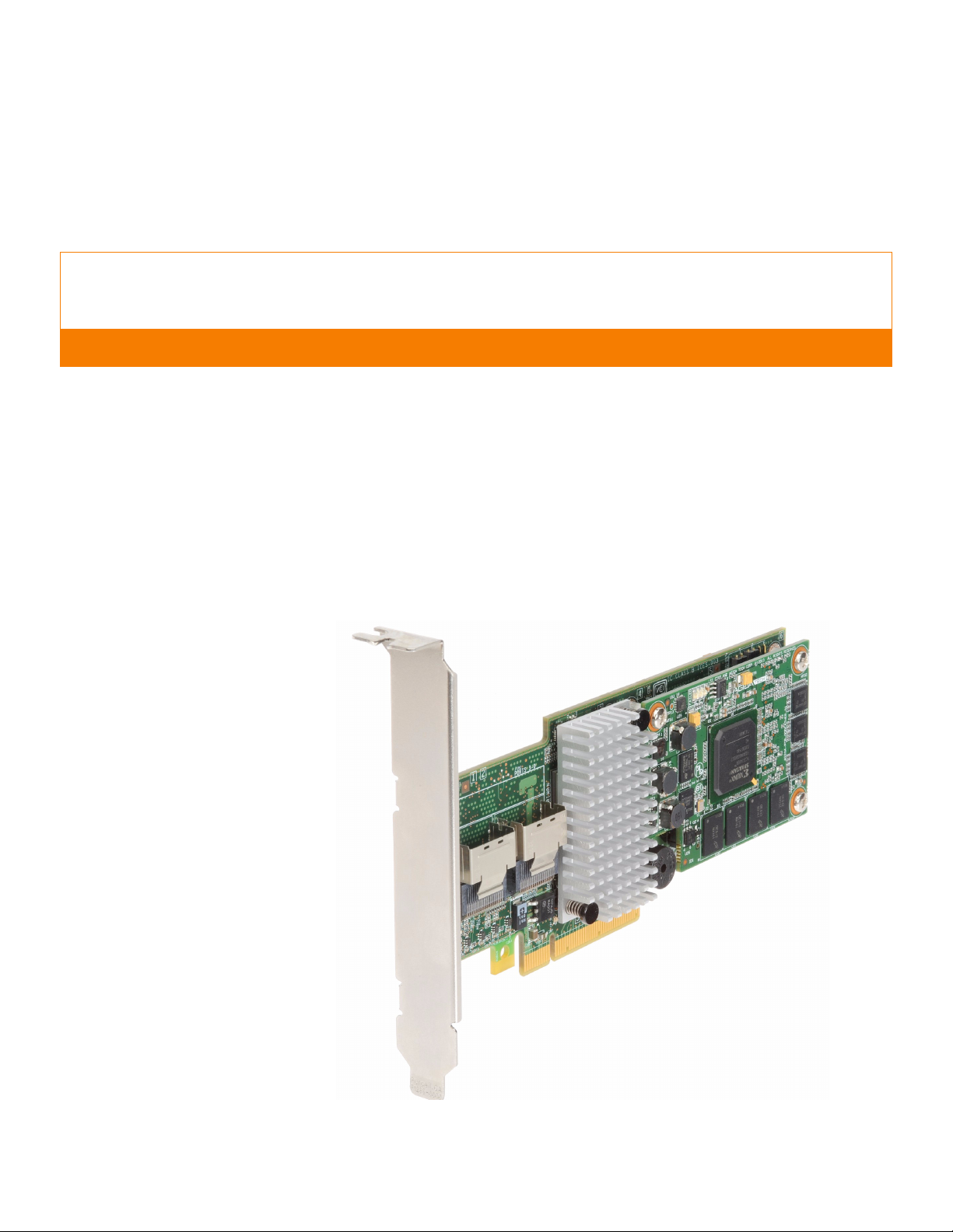
Figure1 shows the MegaRAID SAS 9260CV-8i RAID controller.
Figure 1: MegaRAID SAS 9260CV-8i RAID Controller
6Gb/s SAS 9260CV-8i RAID controller. Your MegaRAID controller
| July 2011 Page 3
Page 4

MegaRAID SAS 9260CV-4i and SAS 9260CV-8i RAID Controller Quick Installation GuideProduct Overview
!
CAUTION
Product Overview This MegaRAID SAS 9260CV RAID controller is a SAS2108 RAID-on-Chip (ROC)-based,
low-profile, PCIe 2.0 internal RAID Host Bus Adapter (HBA) with vertical internal HDD
connectors and non-volatile memory module with cache offload.
The controller offers a 6-Gb/s data transfer rate with the following options:
The SAS 9260CV-4i RAID controller controls four internal SAS or SATA ports through
one SFF-8087 x4 internal connector.
The SAS 9260CV-8i RAID controller controls eight internal SAS or SATA ports
through two SFF-8087 x4 internal connectors.
The MegaRAID SAS RAID controller has a CacheVault Flash Module. This includes
on-board 512MB non-volatile DDR2 800MT/s memory. The CVFM01 connects to a
remote CVPM01 power module. The CVPM01 provides power while the contents of the
DRAM cache are being transferred to NAND flash in the event of power or server failure.
The CVPM01 unit is an intelligent backup power supply solution. It provides capacitor
charge maintenance and capacitor health monitoring functions similar to those of an
intelligent Battery Backup Unit (iBBU). The CVPM01 unit provides sufficient energy to
transfer the cache memory contents from DRAM to a non-volatile flash memory array
on the CVFM01 for cache data retention up to three years.
Installing the RAID Controller
NOTE: Record your controller serial number in a safe location in case you need to
contact LSI.
NOTE: SATA II is the only type of SATA supported by this RAID controller.
Back up your data before changing your system configuration.
Otherwise, you might lose data.
1. Unpack the RAID Controller
Unpack the RAID controller in a static-free environment. Remove it from the
antistatic bag, and inspect it for damage. If the RAID controller appears to be
damaged, or if the MegaRAID Universal Software Suite CD is missing, contact LSI or
your MegaRAID OEM support representative.
The CD contains utility programs, device drivers for various operating systems, and
the following documentation:
— MegaRAID 6Gb/s SAS RAID Controllers User Guide
— MegaRAID SAS Software User Guide
— MegaRAID Advanced Services Hardware Key Quick Installation Guide
— MegaRAID SAS Device Driver Installation User Guide
— Cache Backup Products for MegaRAID SAS RAID Controllers User Guide
— Software license agreement
2. Prepare the Computer
Page 4 | July 2011
Page 5
MegaRAID SAS 9260CV-4i and SAS 9260CV-8i RAID Controller Quick Installation Guide Installing the RAID Controller
!
CAUTION
85081-00
JT1A1
JT1A2
JT1A3
Ports 3-0Ports 7-4
JT1A4
JT1B1
JT2B1
JT2B2
JT1B2
JT6A1
JT6A2
JT6A3
J5A1
Turn off the computer, and unplug the power cords from the rear of the power
supply. Remove the cover from the computer.
Before you install the RAID controller, make sure that the computer is
disconnected from the power and from any networks.
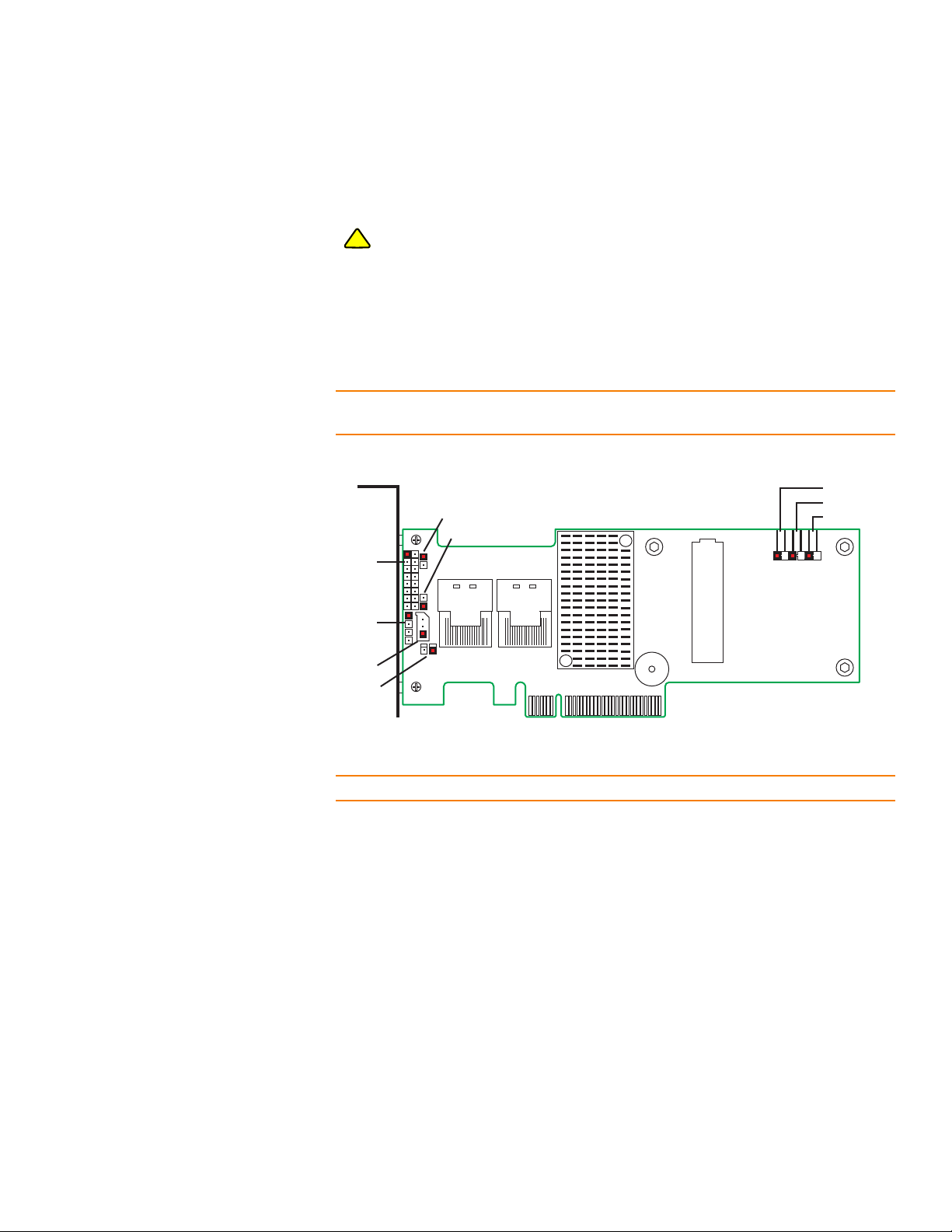
3. Review the Jumpers and the Connectors
Figure2 shows the location of the jumpers and the connectors on the RAID
controller. The jumpers are set at the factory, and you do not usually need to change
them.
NOTE: The SAS 9260CV-4i RAID controller does not contain the JT2B1 connector, which
supports ports 4–7. The SAS 9260CV-8i RAID controller contains the JT2B1 connector.
Figure 2: Layout of the MegaRAID SAS 9260CV-8i RAID Controller
Tab le 1 describes the jumpers and the connectors on the RAID controller.
NOTE: Pin 1 on the headers and connectors is highlighted in red in Figure2.
LSI Corporation Confidential | July 2011 Page 5
Page 6

MegaRAID SAS 9260CV-4i and SAS 9260CV-8i RAID Controller Quick Installation GuideInstalling the RAID Controller
JT1A1
PORT 0
PORT 7
+ve
-ve
ak
Table 1: Jumpers and Connectors
Jumper/
Connector
J5A1 Board-to-board mezzanine
connector
JT1A1 LED Locate and Fault Indication
header
Ports 3-0
Ports 7-4
Type Description
Non-volatile memory module interface
The RAID controller is attached directly to
CVFM01 non-volatile memory
the
module using the J5A1 board-to-board
mezzanine connector.
2x8-pin header
Connects to an LED array that indicates
whether a drive is in a fault condition.
There is one LED per port. When lit, each
LED indicates that the corresponding
drive has failed or is in the
Unconfigured-Bad state.
The LEDs function in a direct-attach
configuration (there are no SAS
expanders). Direct attach is defined as a
maximum of one drive connected directly
to each port.
NOTE: This is a 2x4 pin header on the
SAS 9260CV-4i RAID controller, for
ports 3-0.
JT1A2 LSI Internal use header Reserved for LSI internal use.
JT1A3 SBR Firmware Recovery header 2-pin header
The SBR FW recovery header is used when
SBR corruption is suspected. Installing the
jumper allows the unit to boot while
bypassing the SBR information. You can
then reprogram the SEEPROM using
external utility software. No jumper is
present for normal operation.
Page 6 | July 2011
JT1A4 Serial UART header Reserved for LSI internal use.
JT1B1 SEP Enclosure Support header 3-pin header
Used for connection to the Port0
enclosure.
JT1B2 RAID Key Socket 2-pin header
The RAID Key socket is used when a
feature upgrade requires the use of a
modular RAID Key to be installed to
activate the feature.
Page 7

MegaRAID SAS 9260CV-4i and SAS 9260CV-8i RAID Controller Quick Installation Guide Installing the RAID Controller
JT6A1
ak
+ve
-ve
JT6A2
+ve
ak
-ve
JT6A3
ak
+ve -ve
Table 1: Jumpers and Connectors (Continued)
Jumper/
Connector
JT2B1 x4 SAS Ports 7–4 Mini-SAS 4i internal
connector
Type Description
SFF-8087 x4 internal mini SAS connector
Connects the controller by cable to SAS
drives or SATA 2 drives.
NOTE: The SAS 9260CV-4i RAID
controller does not contain the
JT2B1 connector.
JT2B2 x4 SAS Ports 3–0 Mini-SAS 4i internal
connector
JT2B3 Standard edge card connector The RAID controller interfaces with the
JT6A1 Global drive fault LED header 2-pin connector
SFF-8087 x4 internal mini SAS connector
Connects the controller by cable to SAS
drives or SATA 2 drives.
host system though a standard edge card.
This interface provides power to the
controller and an I
to the I2C bus for IPMI.
Connects to an LED that indicates whether
a drive is in a fault condition.
2
C interface connected
JT6A2 Hard disk drive activity LED header 2-pin connector
Connects to an LED that indicates activity
on the drives connected to the controller.
JT6A3 Write pending LED header 2-pin connector
Connects to an LED that indicates when
the data in the cache has yet to be written
to the storage devices. Used when the
write-back feature is enabled.
4. Connect the RAID Controller to the CVFM01
To connect the CVFM01 flash memory module on the RAID controller to a remote
CVPM01 unit, follow these steps.
a. Mount the CVFM01 unit to the chassis of your computer based on the location
and the type of mounting option.
LSI Corporation Confidential | July 2011 Page 7
Page 8

MegaRAID SAS 9260CV-4i and SAS 9260CV-8i RAID Controller Quick Installation GuideInstalling the RAID Controller
85081-03
T/N
221038 00135
T/N 221038 00135
S/N
021038 00000140
S/N021038 00000140
NOTE: Because server and workstation chassis vary from vendor to vendor, no standard
mounting option for the CVPM01 unit exists that is compatible with the various system
configurations. Authorized resellers and chassis manufacturers can customize the
location of the power module to provide the most flexibility within various
environments.
b. With the controller on a flat, clean, static-free surface, ground yourself, and make
sure the system is grounded.
c. Remove the cable included in the RAID controller box.
d. Insert one end of the cable into the 15-pin P3 cable connector on the CVFM01
and the other end into the 15-pin P1 cable connector on the remote CVPM01, as
shown in Figure3.
Align the recessed triangle indicators on the connectors to make sure
they are connected properly.
NOTE: The cable connectors are polarized. You can insert them into the connectors on
the flash module and the remote power module only if the rails on the cable connectors
align with the slots on the other connectors. Do not force the cable into the 15-pin
connectors. The cable end inserts into the connector with minimal resistance.
Figure 3: Connecting the CVFM01 Flash Module to the Remote CVPM01 Power Module
5. Install the RAID Controller
Page 8 | July 2011
To install and secure the RAID controller, follow these steps.
Page 9

MegaRAID SAS 9260CV-4i and SAS 9260CV-8i RAID Controller Quick Installation Guide Installing the RAID Controller
85081-04
Screw
PCI Socket
Edge of
Motherboard
Press
Here
Press
Here
T/N 221038 00135T/N 221038 00135
S/N021038 00000140S/N021038 00000140
a. Insert the controller into a PCI Express® slot on the motherboard, as shown in
Figure4.
b. Press down gently, but firmly, to seat the card correctly in the slot.
c. Secure the RAID controller to the computer chassis with the bracket screw.
NOTE: The MegaRAID SAS 9260CV-4i RAID controller and the MegaRAID SAS 9260CV-8i
RAID controller are PCI Express x8 cards and they can operate in x8 or x16 slots. However,
some PCIe slots support only PCIe graphics cards, and if you install a RAID controller, it
will not function. Refer to the guide for your motherboard for information about the
PCIe slot.
Figure 4: Installing the MegaRAID SAS 9260CV-8i RAID Controller
6. Configure and Install the SAS Devices, SATA II Devices, or Both in the Host
Computer Case
Refer to the documentation for the devices for any preinstallation configuration
requirements.
7. Connect the RAID Controller to the SAS Devices, SATA II Devices, or Both in the
Host Computer Case
Use SAS cables to connect the RAID controller to SAS devices, SATA II devices, or
both. See Figure2 to view the connector locations.
LSI Corporation Confidential | July 2011 Page 9
Page 10

MegaRAID SAS 9260CV-4i and SAS 9260CV-8i RAID Controller Quick Installation GuideInstalling the RAID Controller
NOTE: Refer to the MegaRAID 6Gb/s SAS RAID Controllers User Guide on the
MegaRAID Universal Software Suite CD for detailed information about the SAS cables.
8. Turn on the Power to the Computer
Reinstall the computer cover, and reconnect the power cords. Turn on the power to
the computer.
Make sure that the power is turned on to the SAS devices and the SATA II devices
before or at the same time that the power to the host computer is turned on. If the
power is turned on to the computer before it is turned on to the devices, the
computer might not recognize the devices.
The firmware takes several seconds to initialize. During this time, the controller
scans the ports.
9. Run the WebBIOS Configuration Utility
Run the WebBIOS Configuration Utility to configure the groups and the virtual
drives. When the message Press <Ctrl><H> for WebBIOS appears on the
screen, immediately press CTRL+H to run the utility.
NOTE: Refer to the MegaRAID SAS Software User Guide on the MegaRAID Universal
Software Suite CD for detailed steps on configuring groups and virtual drives.
10. Install the Operating System Driver
The controller can operate under various operating systems, but you must install
the software drivers first.
The MegaRAID Universal Software Suite CD includes the software drivers for the
supported operating systems, along with documentation. You can view the
supported operating systems and download the latest drivers for RAID controllers
from the LSI web site at: http://www.lsi.com/cm/DownloadSearch.do. Access the
download center, and follow the steps to download the driver.
NOTE: Refer to the MegaRAID SAS Device Driver Installation User Guide on the
MegaRAID Universal Software Suite CD for more information about installing the driver.
Make sure you use the latest service packs that are provided by the operating system
manufacturer and review the readme file that accompanies the driver..
Page 10 | July 2011
Page 11

MegaRAID SAS 9260CV-4i and SAS 9260CV-8i RAID Controller Quick Installation Guide LEDs on the CVFM01 Flash Module
LEDs on the CVFM01 Flash Module
The LEDs on the CVFM01 flash module identify various system conditions and states,
such as power states, activity states, and system condition. Tab le 2 identifies these
conditions and states.
Table 2: LED Status on the CVFM01 Flash Module
LED Name and
Color
DS1 - green On CVFM01 power is present.
DS2 - blue Fast blink A Power-on Restore action or a Force Restore action is in
DS5 - yellow On Fault indicated on CVFM01 cache offload system.
LED State LED Meaning
Off CVFM01 power is not present.
progress.
Fast b link A Power-off Save action or a Force Save action is in
progress.
On When the Restore operation is complete, SDRAM has
switched to host control
Slow blink The backup is complete and the residual capacitor
charge is bleeding off.
Off The Save operation is complete.
Off Normal operation.
LEDs on the CVPM01 Power Module
The LEDs on the CVPM01 power module identify various system conditions and states,
such as power states, activity states, and system condition. Tab le 3 identifies these
conditions and states.
Table 3: LED Status on the CVPM01 Power Module
LED Name and
Color
D3 - green On 12 volts of power are present.
DS2 - green Fast blink The CVPM01 unit is charging.
DS5 - yellow On Fault indicated on CVPM01 power module.
LED State LED Meaning
Off 12 volts of power are not present.
On The CVPM01 unit has completed charging.
Slow blink The Save action is complete and residual energy is
bleeding off.
Off The CVPM01 unit has completed discharging.
Off Normal Operation.
Supported RAID Levels This RAID controller supports drive groups using the following RAID levels:
RAID 0 (data striping): Data is striped across all drives in the group, enabling very
fast data throughput. There is no data redundancy. All data is lost if any drive fails.
LSI Corporation Confidential | July 2011 Page 11
Page 12

MegaRAID SAS 9260CV-4i and SAS 9260CV-8i RAID Controller Quick Installation GuideTechnical Support
RAID 1 (drive mirroring): Data is written simultaneously to both drives in the drive
group, providing complete data redundancy if one drive fails. RAID 1 supports an
even number of drives from 2 to 32 in a single span.
RAID 5 (drive striping with distributed parity): Data is striped across all drives in
the group. Part of the capacity of each drive stores parity information that
reconstructs data if a drive fails. RAID 5 provides good data throughput for
applications with high read request rates.
RAID 6 (drive striping with distributed parity across two drives): Data is striped
across all drives in the group and two parity drives are used to provide protection
against the failure of up to two drives. In each row of data blocks, two sets of parity
data are stored.
RAID 00 (data striping across RAID 0 drive groups): RAID 00 is a spanned drive
group that creates a striped set from a series of RAID 0 drive groups.
RAID 10 (RAID 1 and RAID 0 in spanned groups): RAID 10 uses mirrored pairs of
drives to provide complete data redundancy. RAID 10 provides high data
throughput rates.
RAID 50 (RAID 5 and RAID 0 in spanned groups): RAID 50 uses both parity and
drive striping across multiple drives to provide complete data redundancy. RAID 50
provides high data throughput rates.
RAID 60 (RAID 6 and RAID 0 in spanned groups): RAID 60 uses both distributed
parity across two parity drives and drive striping across multiple drives to provide
complete data redundancy and high fault tolerance.
NOTE: Refer to the MegaRAID SAS Software User Guide on the MegaRAID Universal
Software Suite CD for more information about RAID levels
Technical Support For assistance in installing, configuring, or running the your RAID controller, or the flash
module, contact an LSI Technical Support representative.
Click the following link to access the LSI Technical Support page for storage and
controller support:
http://www.lsi.com/support/storage/tech_support/index.html
From this page, you can send an email or call Technical Support, or submit a new
service request and view its status.
Support Request:
http://www.lsi.com/support/support_form.html
Phone Support:
http://www.lsi.com/support/storage/phone_tech_support/index.html
1-800-633-4545 (North America)
00-800-5745-6442 (International)
NOTE: The international toll-free number does not require country-specific access
codes.
Page 12 | July 2011
Page 13

Page 14

 Loading...