

Page 1

AcceleRAID 160
Quick Installation Guide
DB11-000021-00 First Edition
08P5510
Page 2

Electromagnetic Compatibility Notices
This device complies with Part 15 of the FCC Rules. Operation is subject to
the following two conditions:
1. This device may not cause harmful interference, and
2. This device must accept any interference received, including interference
that may cause undesired operation.
This equipment has been tested and found to comply with the limits for a
Class B digital device, pursuant to part 15 of the FCC Rules. These limits are
designed to provide reasonable protection against harmful interference in a
residential installation. This equipment generates, uses, and can radiate radio
frequency energy and, if not installed and used in accordance with the
instructions, may cause harmful interference to radio communications.
However, there is no guarantee that interference will not occur in a particular
installation. If this equipment does cause harmful interference to radio or
television reception, which can be determined by turning the equipment off
and on, the user is encouraged to try to correct the interference by one or
more of the following measures:
Reorient or relocate the receiving antenna.
Increase the separation between the equipment and the receiver.
Connect the equipment into an outlet on a circuit different from that to
which the receiver is connected.
Consult the dealer or an experienced radio/TV technician for help.
Shielded cables for SCSI connection external to the cabinet are used in the
compliance testing of this Product. LSI Logic is not responsible for any
radio or television interference caused by unauthorized modification of this
equipment or the substitution or attachment of connecting cables and
equipment other than those specified by LSI Logic. The correction of
interferences caused by such unauthorized modification, substitution, or
attachment will be the responsibility of the user.
The LSI Logic Mylex AcceleRAID 160 is tested to comply with FCC
standards for home or office use.
Page 3
This Class B digital apparatus meets all requirements of the Canadian
Interference-Causing Equipment Regulations.
Cet appareil numérique de la classe B respecte toutes les exigences du
Règlement sur le matériel brouilleur du Canada.
This is a Class B product based on the standard of the Voluntary Control
Council for Interference from Information Technology Equipment (VCCI).
If this is used near a radio or television receiv er in a domestic en vironment, it
may cause radio interference. Install and use the equipment according to the
instruction manual.
LSI Logic Corporation
North American Headquarters
Milpitas, CA
408.433.8000
Page 4

Declaration of Conformity
Per FCC Part 2, Section 2.1077(a)
Manufacturer’s Name: LSI Logic Corporation
Manufacturer’s Address:
Declares that the product:
Product Name: AcceleRAID 160 PCI to Ultra 160 SCSI RAID
Model Number(s): A160-1-16NB
Year of Manufacture: 2000
Conforms to the following Product Specification(s):
FCC: CFR 47 Part 15, Subpart B, Section 15.107(e)
Supplementary Information:
This device complies with part 15 of the FCC Rules. Operation is subject to
the following two conditions: (1) This device may not cause harmful
interference, and (2) this device must accept any interference received,
including interference that may cause undesired operation.
North American Headquarters
Milpitas, CA
USA
Controller
and Section 15.109(g) Class B Digital Device
tested per ANSI C63.4–1992 procedures
Page 5

Declaration of Conformity
Per 89\336\EEC
Responsible Party
Name:
Address:
Trade Name: AcceleRAID 160 PCI to Ultra 160 SCSI RAID
Model Number(s):A160-1-16NB
Standards: EN 50081-1:1992, Emissions
LSI Logic Corporation
North American Headquarters
Milpitas, CA
U.S.A.
hereby declares that the product
Controller
Fab 550167-01 Rev A
conforms to the following specifications
EN 55022:1998 Class B ITE radiated and conducted
emissions
EN 50024:1998, Immunity
EN 61000-4-2:1998 Electrostatic Discharge
EN 61000-4-3:1998 Radiated Immunity
EN 61000-4-4:1995 Electrical Fast Transients/Burst
EN 61000-4-5:1995 Surges
EN 61000-4-6:1996 Conducted Immunity
EN 61000-4-11:1994 Supply Dips and Variations
Page 6

Community of Europe
CE mark is rated for the AceleRAID 160 as follows:
CISPR 22 Radiated Emission
EN55022, Generic immunity standard for the following:
IEC 801-2 ESD, IEC 801-3 Radiated, and IEC 801-4 EFT/Burst
Warning!
This is a Class B product. In a residential environment this product may
cause radio interference, in which case the user may be required to take
adequate measures.
Achtung!
Dieses ist ein Gerät der Funkstörgrenzwertklasse B. In Wohnbereichen
können bei Betrieb dieses Gerätes Rundfunkstörungen aufreten, in welchen
Fällen der Benutzer für entsprechende Gegenmaßnahmen verantwortlich ist.
Avertissement!
Cet appareil est un appareil de Classe B. Dans un environnement résidentiel
cet appareil peut provoquer des brouillages radioélectriques. Dans ce cas, il
peut être demandé à l’utilisateur de prendre des mésures appropriées.
Page 7

Underwriters Laboratories Statement and Warning
Page 8

Proprietary Rights Notice
This document contains proprietary information of LSI Logic
Corporation. The information contained herein is not to be used by
or disclosed to third parties without the express written permission
of an officer of LSI Logic Corporation. Any product(s) described
herein is/are a licensed product of LSI Logic Corporation.
Document Description
Document DB11-000021-00 First Edition. November 2002
This document describes the LSI Logic Corporation’s Mylex
AcceleRAID 160 product for Software Kit 5.20 and will remain the
official reference source for all revisions/releases of this product
until rescinded by an update.
Disclaimer
It is the policy of LSI Logic to improve products as new technology ,
components, software, and firmware become available. LSI Logic
Corporation reserves the right to make changes to any products
herein at any time without notice. All features, functions, and
operations described herein may not be marketed by LSI Logic in
all parts of the world. In some instances, photographs and figures
are of equipment prototypes. Therefore, before using this
document, consult your LSI Logic representative for information
that is applicable and current. LSI LOGIC DOES NOT ASSUME
ANY RESPONSIBILITY OR LIABILITY FOR THE USE OF
ANY PRODUCT(S) DESCRIBED HEREIN EXCEPT AS
EXPRESSLY AGREED TO IN WRITING BY LSI LOGIC.
License Restriction
The purchase or use of an LSI Logic product does not convey a
license under any patent, copyright, trademark, or other intellectual
property right of LSI Logic or third parties.
Copyright Notice
Copyright © 2001, 2002. LSI Logic Corporation. All rights
reserved.
Page 9

Trademark Acknowledgments
LSI Logic, the LSI Logic logo, MORE, Mylex, and SANmapping
are trademarks or registered trademarks of LSI Logic Corporation.
All other brand and product names may be trademarks of their
respective companies.
Page 10

Page 11

Contents
Hardware Installation
Introduction ........................................................................................ 1-1
Performing an Installation ..................................................................1-1
PCI Hot Plug ............................................................. ... ..............1-1
Connectors, LEDs, and Jumpers ...............................................1-2
Installing the AcceleRAID 160 into a Standard Chassis ............. 1-5
Installing the AcceleRAID 160 into a 2U Chassis ....................... 1-9
What to Do Next ..............................................................................1 -13
SOFTWARE LICENSE AND WARRANTY POLICY
Manual No. DB11-000021-00 1
Page 12

2 AcceleRAID 160 Installation Guide
Page 13

Hardware Installation
Introduction
The AcceleRAID 160 is a versatile single channel PCI to Ultra 160 SCSI,
Low Voltage Differential (LVD) RAID controller with many possible
hardware configurations. This quick installation guide assumes that the user
is familiar with controller, disk drive, and RAID terminology.
Performing an Installation
☛Note
A PCI 2.2 compliant slot is required to operate the
AcceleRAID 160 controller. However, a PCI 2.1
compliant slot that supplies 5V power is acceptable.
WARNING
To avoid electrical shock, do not attempt to
perform this hardware installation with the power
on. Disconnect the system from the electrical wall
outlet.
PCI Hot Plug
Please refer to Appendix C in the AcceleRAID 160 PCI to Ultra 160 SCSI
RAID Controller Installation Guide for instructions on how to use the PCI
Hot Plug feature.
Manual No. DB11-000021-00 1
Page 14

Performing an Installation
Connectors, LEDs, and Jumpers
There is one external and one internal connector supported on the
AcceleRAID 160 controller. The locations of the SCSI connectors are sho wn
in Figure 1 and Figure 2 and are labeled as CH 0.
There are two types of brackets: Standard PCI bracket (Figure 1) and Low
Profile PCI bracket (Figure 2).
CH 0
CH 0
Figure 1. AcceleRAID 160 Controller with Channel 0 Connectors and
CH 0
Figure 2. AcceleRAID 160 Controller with Channel 0 Connectors and
2 AcceleRAID 160 Quick Installation Guide
Standard PCI Bracket
CH 0
Low Profile PCI Bracket
Page 15
Hardware Installation
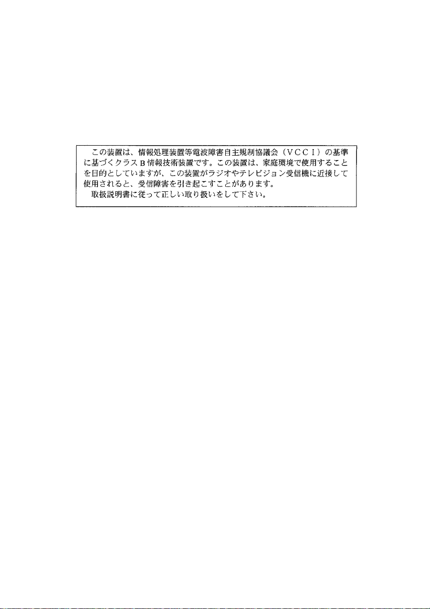
The front side of the controller has four LEDs that are illustrated in Figure 3
and described in Table 1.
D1 D2 D3 D4
Figure 3. AcceleRAID 160 LEDs (front)
Table 1. LED Descriptions (front)
D1 FAIL (Processor Self Test)
D2
D3 S0_LVD Mode
D4 S0_SE (Single Ended) Mode
Manual No. DB11-000021-00 3
TERM_LED (Terminator Enabled)
Page 16
Performing an Installation
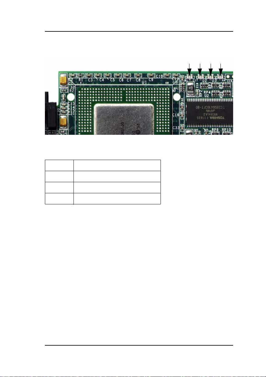
All the jumpers should normally be set to their default settings. Jumper
locations are illustrated in Figure 4 and described in Table 2.
JP1
Figure 4. AcceleRAID 160 Jumper Locations
Table 2. AcceleRAID 160 Jumper Descriptions
JP1 SCSI Activities LED Header
JP3 Maintenance Mode
J1
JP3 JP4
JP4 Cache dirty (monitor cache write back) — LED Header
J1 Debug serial edge connector
If you have any diff iculty with the operation or diagnostics of this controller,
contact Customer Support to see if any of the above jumpers need to be
adjusted.
4 AcceleRAID 160 Quick Installation Guide
Page 17
Hardware Installation
Installing the AcceleRAID 160 into a Standard Chassis
If your system has a 2U chassis, please go to “Installing the AcceleRAID
160 into a 2U Chassis” on page 9.
Caution
Be sure to wear a ground wrist strap at all times.
☛Note
If the controller has the Low Profile Bracket attached,
replace it with the Standard PCI bracket for this
installation.
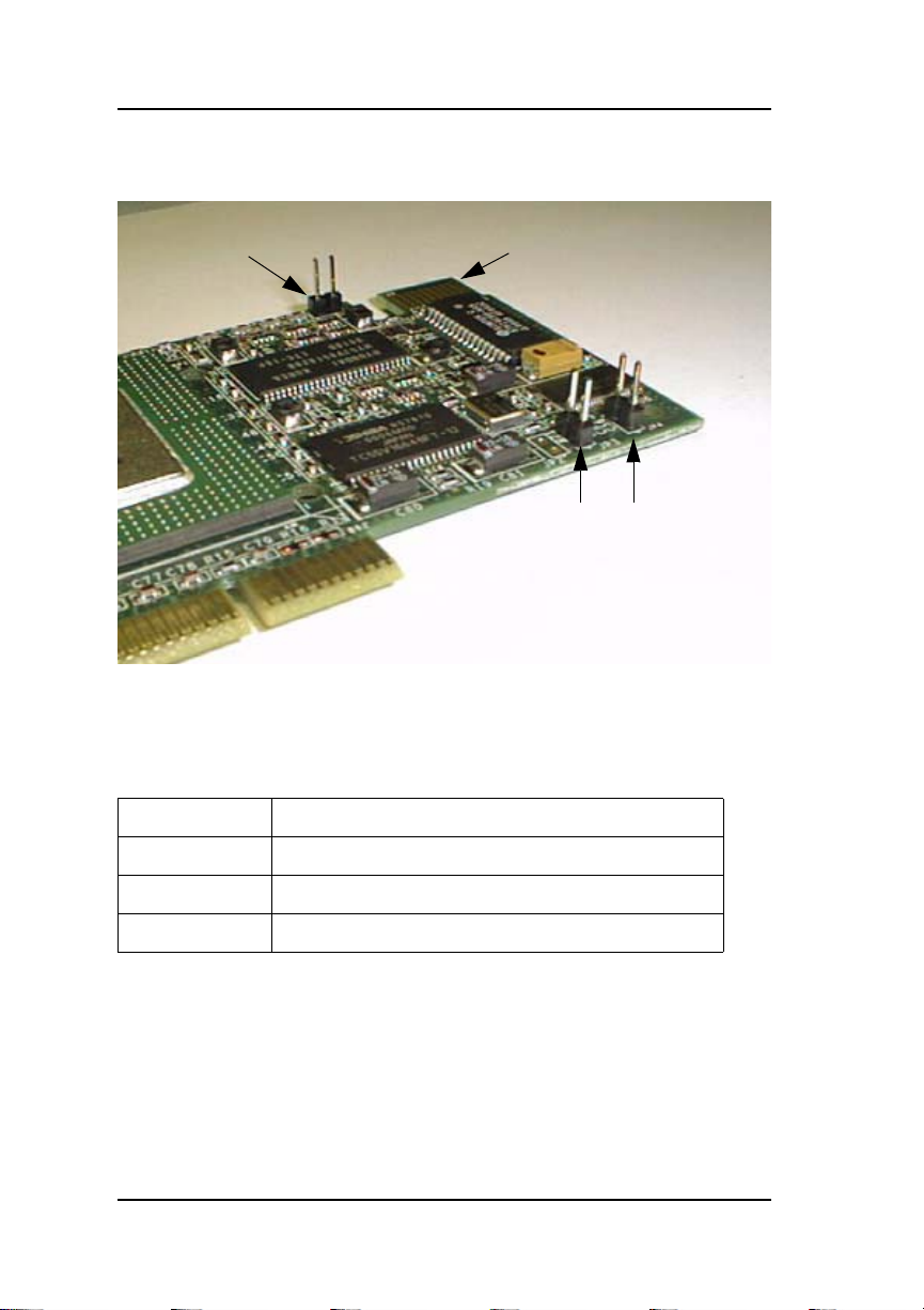
1. With the power off, plug the AcceleRAID 160 controller into an
available 32-bit PCI slot on the system board (see Figure 5); the 32-bit
slot is short.
32-bit PCI
Ground
Wrist
Strap
Figure 5. Plugging the AcceleRAID 160 into a PCI Slot
2. Set the SCSI ID on each internal drive to a unique address between
0 and 15, but do not use address 7, as it is reserved for the controller.
See the documentation that comes with your drives for instructions on
how to set the SCSI ID address.
AcceleRAID
160
Ground Clip
Caution
If internal and external drives are used, be sure that
drive addresses are NOT duplicated. External SCSI
cabinets usually automatically assign drive addresses
according to the drives’ location in the cabinet.
Manual No. DB11-000021-00 5
Page 18
Performing an Installation
3. Be sure termination is disabled on all SCSI drives connected to the
controller. See the documentation that comes with your drives for
instructions on how to do this. (T ermination must be enabled on the last
device, if not using an active terminator.)
4. Be sure that termination power is enabled on all SCSI drives connected
to the controller. See the documentation that comes with your dri ves for
instructions on how to do this.
Connecting Internal SCSI Devices
5. If you are installing internal SCSI devices to the controller, connect a
wide, high-density, 68-pin SCSI ribbon cable to the internal SCSI
connector on the AcceleRAID 160 controller and connect the other
cable connectors to any SCSI devices as required (see Figure 6).
Termination is automatic on the AcceleRAID 160.
6. Connect an active terminator to the last device at the end of the SCSI
ribbon cable (see Figure 6).
Figure 6. Connecting Internal SCSI Devices
6 AcceleRAID 160 Quick Installation Guide
Page 19

Hardware Installation
Connecting External SCSI Devices
7. If you are installing external SCSI devices to the controller,
individually or in an external drive cabinet, connect a cable, with the
68 pin VHDCI, to the external SCSI connector on the AcceleRAID 160
controller. Connect the other end of the cable connector to other
devices or to a SAF-TE external drive cabinet, as required
(see Figure 7).
8. External drive cabinets usually have termination built into the end of
the SCSI bus. Check the documentation that comes with your drive
cabinet to be sure this is the case. If not, use an active terminator at the
end of the bus.
☛Note
AcceleRAID 160 termination is enabled by default,
but will be automatically disabled if necessary.
Figure 7. Connecting External SCSI Devices
Manual No. DB11-000021-00 7
Page 20

Performing an Installation
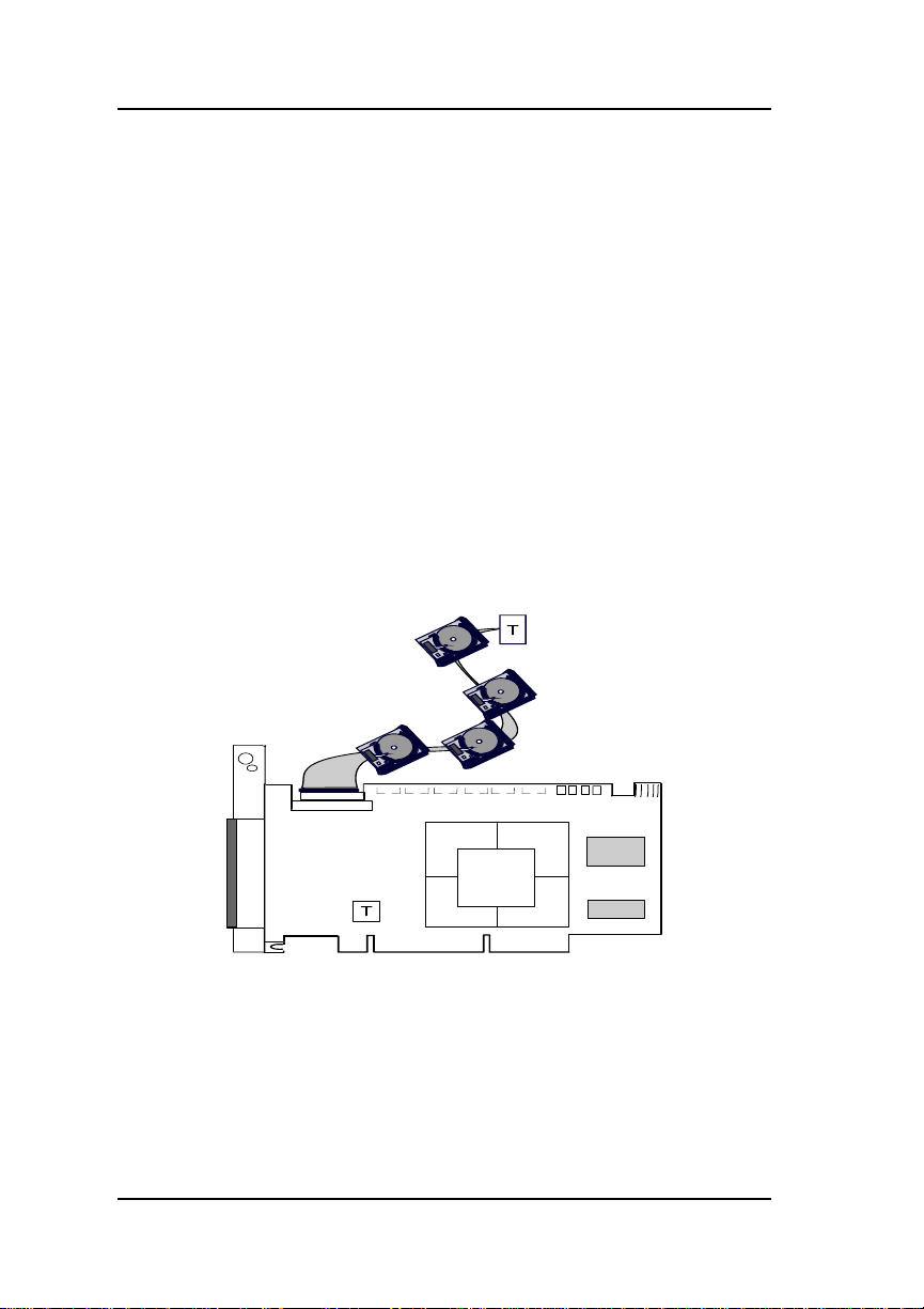
Connecting Both Internal and External SCSI Devices
A combined installation showing internal and external devices with proper
termination is illustrated in Figure 8.
☛Note
A combined configuration using both internal and
external connectors works best with high quality
cables. It is recommended that you use an
Amphenol® Fast LVD an d a Hitachi ® twisted pair,
flat cable in this unique setup.
Figure 8. Connecting Both Internal and External SCSI Devices
The hardware portion of the installation is complete.
Please see the section called “What to Do Next,” at the end of this manual.
8 AcceleRAID 160 Quick Installation Guide
Page 21

Hardware Installation
Installing the AcceleRAID 160 into a 2U Chassis
You may need to check the manufacturer’s installation instru ctions for your
particular 2U chassis.
Caution
Be sure to wear a ground wrist strap at all times.
☛Note
If the controller has the Standard PCI bracket
attached, replace it with the Low Profile PCI bracket
for this installation.
1. Choose the riser adapter with an available PCI slot. In this case, it is
presented on an angle, as shown in Figure 9.
2. Plug (install) the controller board firmly into the 32-bit PCI slot, and
snap it into place, as shown in Figure 9.
Figure 9. Plug the Controller into a 32-bit PCI Slot on the 2U Chassis
Manual No. DB11-000021-00 9
Page 22

Performing an Installation
In the finished installation, the controller will be in a flat, horizontal
position, as shown in Figure 10.
Figure 10. AcceleRAID 160 Installed into a 2U Chassis
32-Bit PCI
Low Profile
Bracket
AR160
3. Set the SCSI ID on each internal drive to a unique address between
0 and 15, but do not use address 7, as it is reserved for the controller.
See the documentation that comes with your drives for instructions on
how to set the SCSI ID address.
Caution
If internal and external drives are used, be sure that
drive addresses are NOT duplicated. External SCSI
cabinets usually automatically assign drive addresses
according to the drives’ location in the cabinet.
10 AcceleRAID 160 Quick Installation Guide
Page 23

Hardware Installation
4. Be sure termination is disabled on all SCSI drives connected to the
controller. See the documentation that comes with your drives for
instructions on how to do this. (T ermination must be enabled on the last
device, if not using an active terminator.)
5. Be sure that termination power is enabled on all SCSI drives connected
to the controller. See the documentation that comes with your dri ves for
instructions on how to do this.
Connecting Internal SCSI Devices
6. If you are installing internal SCSI devices to the controller, connect a
wide, high-density, 68-pin SCSI ribbon cable to the internal SCSI
connector on the AcceleRAID 160 controller and connect the other
cable connectors to any SCSI devices as required (see Figure 11).
Termination is automatic on the AcceleRAID 160.
7. Connect an active terminator to the last device at the end of the SCSI
ribbon cable (see Figure 11).
Figure 11. Connecting Internal SCSI Devices
Manual No. DB11-000021-00 11
Page 24

Performing an Installation
Connecting External SCSI Devices
8. If you are installing external SCSI devices to the controller,
individually or in an external drive cabinet, connect a cable, with the
68 pin VHDCI, to the external SCSI connector on the AcceleRAID 160
controller. Connect the other end of the cable connector to other
devices or to a SAF-TE external drive cabinet, as required
(see Figure 12).
9. External drive cabinets usually have termination built into the end of
the SCSI bus. Check the documentation that comes with your drive
cabinet to be sure this is the case. If not, use an active terminator at the
end of the bus.
☛Note
AcceleRAID 160 termination is enabled by default,
but will be automatically disabled if necessary.
Figure 12. Connecting External SCSI Devices
12 AcceleRAID 160 Quick Installation Guide
Page 25

Hardware Installation
Connecting Both Internal and External SCSI Devices
A combined installation showing internal and external devices with proper
termination is illustrated in Figure 13.
☛Note
A combined configuration using both internal and
external connectors works best with high quality
cables. It is recommended that you use an
Amphenol® Fast LVD and a Hitachi® tw isted pair,
flat cable in this unique setup.
Figure 13. Connecting Both Internal and External SCSI Devices
The hardware portion of the installation is complete.
Please see the following section titled “What to Do Next.”
What to Do Next
1. Use RAID EzAssist to create an automatic or a custom RAID
Configuration.
Refer to the RAID EzAssist Configuration Utility Quick Configuration
Guide or RAID EzAssist Configuration Utility User Reference Guide.
2. Install the AcceleRAID 160 controller drivers appropriate for your
server’s network operating system.
Refer to the PCI Disk Array Controller Driver s Installation Guide and
Manual No. DB11-000021-00 13
Page 26

What to Do Next
User Manual.
14 AcceleRAID 160 Quick Installation Guide
Page 27

LSI LOGIC CORPORATION
SOFTWARE LICENSE AND WARRANTY POLICY
Limited Warranty
LSI warrants to the original purchaser of the product enclosed herein
(“Customer”) that (a) for a period of three (3) years from the date of
Customer’s purchase of the Product (excluding batteries and
memory) (the “Product Warranty Period”), and (b) for a period of one
(1) year from the date of purchase of the Product by Customer (the
“Battery/Memory Warranty Period”), the batteries and memory
included in the Product will (i) be free from defects in workmanship
and materials, and (ii) substantially conform to the documentation or
other specifications for the Product. The limited warranties herein
shall not apply to and shall be void for any Product that has been
misused (including static discharge, improper installation, or
accident), abused, modified, damaged a s a result of actions on the
part of Customer or its agents or its processes, unauthorized service
or parts, used in a manner inconsistent with normal computer
operations (including but not limited to electrical irregularities,
lightning or power line related damage, or other abnormal
occurrences), or to normal wear and tear of the Product. The
warranty herein is made to and for the benefit of the original
purchaser of this Product and is non-transferable.
This warranty will not apply to, and LSI provides no warranty for any
BIOS, software, ROM-based firmware or other product developed or
manufactured b y an y third party whether including with this Product or
not. Such warranty or warranties are provided by third parties and, to
the extent permitted thereby, shall be made available and are hereby
assigned by LSI to Customer.
Customer may obtain warranty service during the Product Warranty
Period or Battery/Memory Warranty Period, as the case may be, if (a)
Customer has contacted LSI at the telephone num ber listed LSI’s web
site at www.lsilogic.com to obtain a Returned Material Authorization
(“RMA”) number and appropriate instructions from LSI, (b) after
obtaining LSI’s au thorization, Customer has returned the Product if so
instructed to an authorized LSI service facility or to LSI in accordance
Page 28

with LSI’s instructions and the terms of this Agreement, shipping
costs to be borne by LSI, and (c) Customer has provided proof of
purchase price and date for unregistered Product. LSI shall bear
one-way shipping, packing and insurance costs and all other costs,
excluding labor and parts, necessary to effectuate repair or
replacement under this warranty. All Product repaired or replaced
under this warranty shall be returned to Customer at Customer’s
expense. Repair or replacement Product provided under this limited
Product warranty will be furnished on an exchange basis and may be
new or reconditioned. All Product returned under this warranty shall
become the property of LSI. LSI shall notify Customer in the event
that the Product returned under the warranty does not, in LSI’s sole
determination, comply with the conditions and requirements set for th
herein and, unless disposition instructions are given by Customer for
the Product within thirty (30) days of such notification, the Product
shall be returned to Customer freight collect.
Warranty Disclaimer
EXCEPT AS SET FORTH IN THIS DOCUMENT, LSI MAKES NO
WARRANTIES, WHETHER EXPRESS, IMPLIED, OR STATUTORY
REGARDING OR RELATING TO THE PRODUCT, OR ANY
MATERIALS OR SERVICES FURNISHED OR PROVIDED TO OEM
UNDER THIS AGREEMENT, INCLUDING MAINTENANCE AND
SUPPORT. LSI SPECIFICALLY DISCLAIMS ALL IMPLIED
WARRANTIES, INCLUDING, WITHOUT LIMITATIO N, THE IMPLIED
WARRANTIES OF NON-INFRINGEMENT, MERCHANTABILITY
AND FITNESS FOR A PARTICULAR PURPOSE WITH RESPECT
TO THE PRODUCT AND ANY OTHER MATERIALS AND
SERVICES, AND WITH RESPECT TO THE USE OF ANY OF THE
FOREGOING.
THE REMEDIES STATED IN THIS DOCUMENT CONSTITUTE
CUSTOMER’S EXCLUSIVE REMEDIES AND LSI’S SOLE
LIABILITY FOR BREACH OF THE LIMITED WARRANTIES SET
FORTH HEREIN.
Software License
Subject to the terms and conditions of this Agreement, LSI grants
Customer a non-exclusive, worldwide, non-transferable, revocable,
royalty-free license to use, perform and display the LSI software that
Page 29

is a part of the Product (“ LSI Software”) solely as par t of the Produc t
incorporated into the OEM Products that and not on a standalone
basis. Customer may not ( a) sell, lease, license, or sublicense the LSI
Software, (b) de-compile, disassemble, reverse engineer, or
otherwise attempt to derive source code from the LSI Software, in
whole or in part, except to the extent such restriction is prohibited by
applicable law, (c) modify or create derivative works from the LSI
Software, or (d) use the LSI Software to provide processing services
to third parties or otherwise use the LSI Software on a service bureau
basis, electronically distribute or timeshare the LSI Software or
market the LSI Software by interactive cable or remote processing
services.
Limitation of Liability
IN NO EVENT SHALL LSI’S TOTAL, CUMULATIVE LIABILITY
ARISING FROM THE SALE, USE AND DISPOSITION OF THE
PRODUCT AND/OR THE LICENSING OF THE LSI SOFTWARE
EXCEED THE AMOUNT PAID BY CUSTOMER FOR THIS
PRODUCT. IN NO EVENT SHALL LSI BE LIABLE TO CUSTOMER
OR ANY THE OTHER FOR ANY PUNITIVE, INCIDENTAL,
INDIRECT, CONSEQUENTIAL OR SPECIAL DAMAGES,
INCLUDING LOSS OF PROFITS, INCURRED BY THAT PARTY,
HOWEVER CAUSED AND UNDER ANY THEORY OF LIABILITY,
WHETHER BASED IN CONTRACT, TORT (INCLUDING, WITHOUT
LIMITATION, NEGLIGENCE OR PRODUCT LIABILITY) OR
WARRANTY, IN CONNECTION WITH THE SALE, USE AND
DISPOSITION OF THE PRODUCT AND/OR THE LICENSING OF
THE LSI SOFTWARE, EVEN IF ADVISED OF THE POSSIBILITY OF
SUCH DAMAGES.
Page 30

Manual No. DB11-000021-00
08P5510
LSI Logic Corporation
North American Headquarters
Milpitas, CA
408.433.8000
 Loading...