

HDLx-2416 Series
Four Character 5.0 mm (0.2 inch) Smart 5x7
Alphanumeric Displays
Data Sheet
Description
These are 5.0 mm (0.2 inch) four character 5 x 7 dot matrix
displays driven by an on-board CMOS IC. These displays are
pin for pin compatible with the HPDL-2416. The IC stores
and decodes 7 bit ASCII data and displays it using a 5 x 7
font. Multiplexing circuitry, and drivers are also part of the
IC. The IC has fast setup and hold times which makes it easy
to interface to a microprocessor.
Absolute Maximum Ratings
Supply Voltage, V
Input Voltage, Any Pin to Ground -0.5 V to VDD + 0.5 V
Free Air Operating Temperature Range, TA -40°C to +85°C
Storage Temperature, TS -40°C to 100°C
CMOS IC Junction Temperature, TJ (IC) +150°C
Relative Humidity (non-condensing) at 65°C 85%
Soldering Temperature [1.59 mm (0.063 in.) Below Body]
Solder Dipping 260°C for 5 secs
Wave Soldering 250°C for 3 secs
ESD Protection, R = 1.5 kΩ, C = 100 pF VZ = 2 kV (each pin)
Note:
1. Maximum Voltage is with no LEDs illuminated.
to Ground
DD
[1]
-0.5 V to 7.0 V
Features
• Enhanced drop-in replacement to HPDL-2416
• Smart alphanumeric display
Built-in RAM, ASCII decoder, and LED drive circuitry
• CMOS IC for low power consumption
• Software controlled dimming levels and blank
• 128 ASCII character set
• End-stackable
• Categorized for luminous intensity; Yellow and Green
categorized for color
• Low power and sunlight viewable AlGaAs versions
• Wide operating temperature range
-40°C to +85°C
• Excellent ESD protection
• Wide viewing angle (50° typ.)
Devices:
AlGaAs Red High Eciency Red Orange Yellow Green
HDLS-2416 HDLO-2416 HDLA-2416 HDLY-2416 HDLG-2416
HDLU-2416 HDLO-2416-DE000 HDLG-2416-FG000
ESD WARNING: Standard CMOS handling precautions should be observed with the HDLX-2416.
25.15
(0.990)
TYP.
6.35
(0.250)
3.05
(0.120)
10.03
(0.395)
20.07
(0.790)
5.08
(0.200)
3.43
(0.135)
0.51 ± 0.13
(0.020 ± 0.005)
TYP.
6.60
(0.260)
2.41
(0.095)
2.54
(0.100)
TYP.
REF.
DATE CODE (YEAR, WEEK)
4.06
(0.160)
10.16
(0.400)
2.41
(0.095)
TYP.
0.38
(0.015)
15.24
(0.600)
0.25 ± 0.13
(0.010 ± 0.005)
TYP.
REF.
1.52
(0.060)
IMAGE PLANE
REF.
REF.
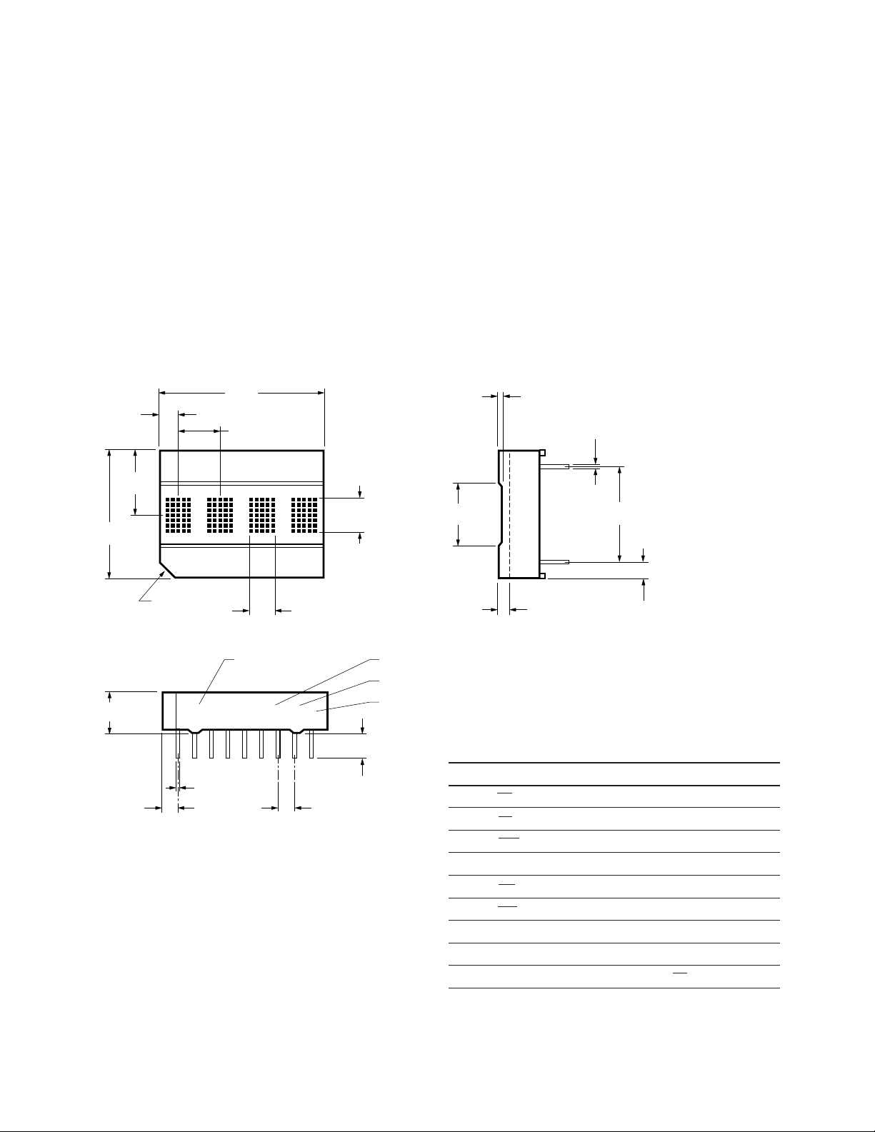
NOTES:
1. UNLESS OTHERWISE SPECIFIED, THE TOLERANCE
ON ALL DIMENSIONS IS ± 0.254 mm (± 0.010).
2. ALL DIMENSIONS ARE IN MILLIMETERS (INCHES).
3. FOR YELLOW AND GREEN DISPLAYS ONLY.
PIN 1 IDENTIFIER
HDLX-2416 YYWW X Z
PART NUMBER
LUMINOUS INTENSITY
COLOR BIN (3)
The address and data inputs can be directly connected to
the microprocessor address and data buses.
The HDLX-2416 has several enhancements over the HPDL-
2416. These features include an expanded character set,
internal 8 level dimming control, external dimming capability, and individual digit blanking. Finally, the extended
functions can be disabled which allows the HDLX-2416 to
operate exactly like an HPDL-2416 by disabling all of the
enhancements except the expanded character set.
Package Dimensions
The dierence between the sunlight viewable HDLS2416 and the low power HDLU-2416 occurs at power-on
or at the default brightness level. Following power up,
the HDLS-2416 operates at the 100% brightness level,
while the HDLU-2416 operates at the 27% brightness
level. Power on sets the internal brightness control (bits
3-5) in the control register to binary code (000). For the
HDLS-2416 binary code (000) corresponds to a 100%
brightness level, and for the HDLU-2416 binary code (000)
corresponds to a 27% brightness level. The other seven
brightness levels are identical for both parts.
Pin No. Function Pin No. Function
1 CE1 Chip Enable 10 GND
2 CE2 Chip Enable 11 D0 Data Input
3 CLR Cle ar 12 D1 Data Input
4 CUE Cursor Enable 13 D2 Data Input
5 CU Cursor Select 14 D3 Data Input
6 WR Write 15 D6 Data Input
7 A1 Address Input 16 D5 Data Input
8 A0 Address Input 17 D4 Data Input
9 VDD 18 BL Display Blank
2
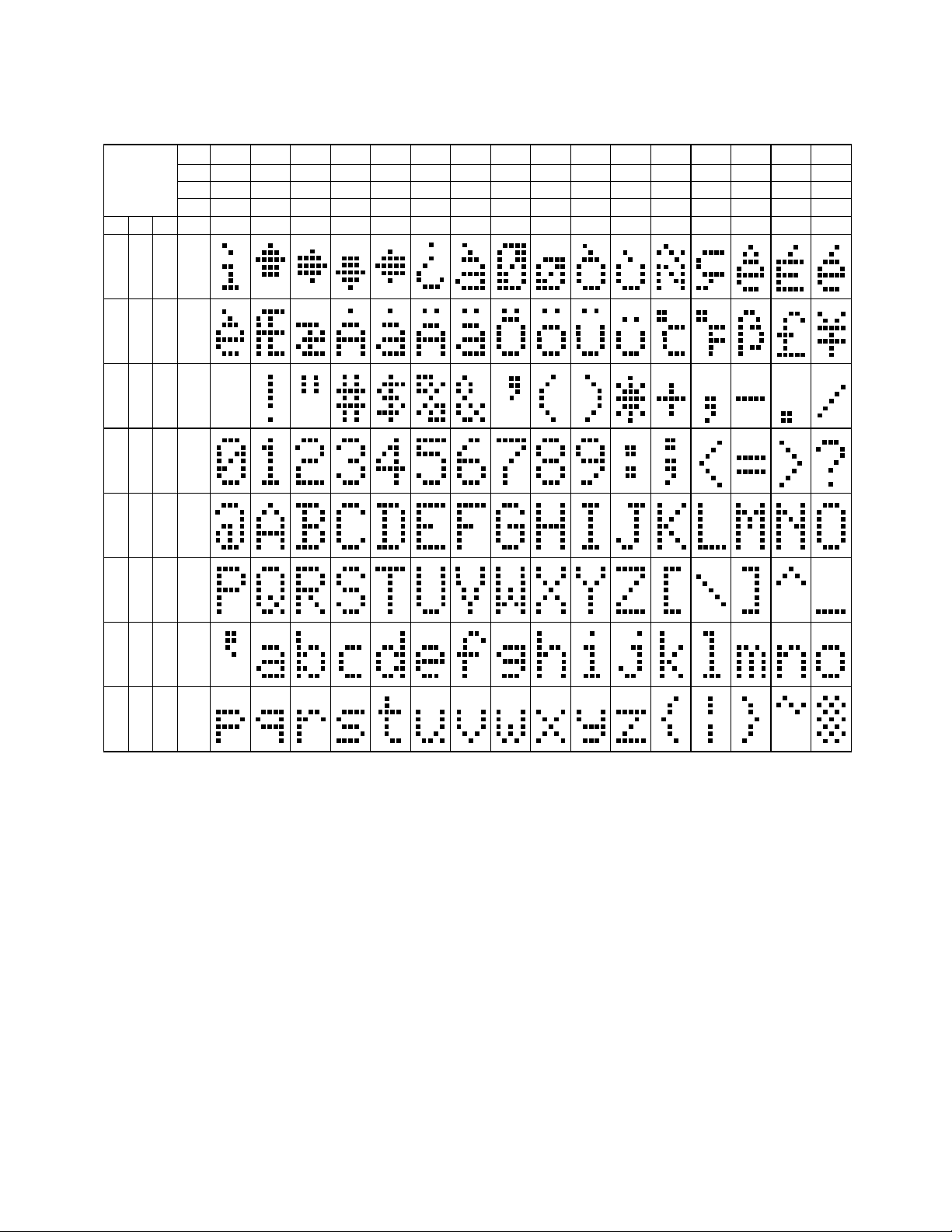
Character Set
ASCII
CODE
D0
D1
D2
D3
HEX
0
0
0
0
0D6 D5 D4
1
0
0
0
1
0
1
0
0
2
1
1
0
0
3
0
0
1
0
4
1
0
1
0
5
0
1
1
0
6
1
1
1
0
7
0
0
0
1
8
1
0
0
1
9
0
1
0
1
A
1
1
0
1
B
0
0
1
1
C
1
0
1
1
D
0
1
1
1
E
1
1
1
1
F
0 0 0 0
0 0 1 1
0 1 0 2
0 1 1 3
1 0 0 4
1 0 1 5
1 1 0 6
1 1 1 7
NOTES: 1 = HIGH LEVEL
0 = LOW LEVEL
3
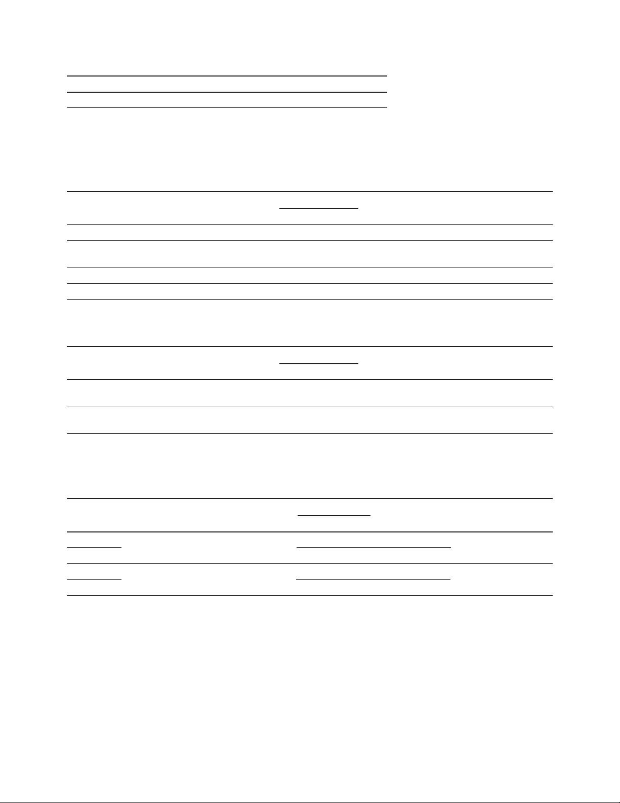
Recommended Operating Conditions
Parameter Symbol Min. Typ. Max. Unit
Supply Voltage VDD 4.5 5.0 5.5 V
Electrical Characteristics over Operating Temperature Range
4.5 < V
< 5.5 V (unless otherwise specied)
DD
All Devices
25°C
[1]
Parameter Symbol Min. Typ. Max. Max. Units Test Conditions
I
Blank I
DD
Input Current II -40 10 µA V
(blnk) 1.0 4.0 mA All Digits Blanked
DD
= 0 V to VDD
IN
VDD = 5.0 V
Input Voltage High VIH 2.0 VDD V
Input Voltage Low VIL GND 0.8 V
HDLO/HDLA/HDLY/HDLG-2416
25°C
[1]
Parameter Symbol Min. Typ. Max. Max. Units Test Conditions
IDD 4 digits IDD(#) 110 135 160 mA “#” ON in All
20 Dots/Character
IDD Cursor All IDD (CU) 92 110 135 mA Cursor ON in All
Dots ON @ 50% Four Locations
[2, 3]
Four Locations
HDLS/HDLU-2416
25°C
[1]
Part Number Parameter Symbol Typ. Max. Max. Units Test Conditions
HDLS-2416 IDD 4 digits IDD(#) 125 146 180 mA Four “#” ON in All
HDLU-2416
20 dots/character
[2,3]
34 42 52
Four Locations
HDLS-2416 IDD Cursor all dots IDD(CU) 105 124 154 mA Four Cursors ON in
HDLU-2416
Notes:
1. VDD = 5.0 V.
2. Average IDD measured at full brightness. Peak I
3. IDD(#) max. = 130 mA for HDLO/HDLA/HDLY/HDLG-2416, 146 mA for HDLS-2416, and 42 mA for HDLU-2416 at default brightness, 150°C IC
junction temperature and VDD = 5.5 V.
ON @ 50%
29 36 45
= 28/15 x Average IDD(#).
DD
All Four Locations
4

Optical Characteristics at 25°C
[1]
VDD = 5.0 V at Full Brightness
HDLS/HDLU-2416
Part Number Parameter Symbol Min. Typ. Units Test Conditions
HDLS-2416 Average Luminous Intensity per IV 4.0 12.7 mcd ‘’*’’ Illuminated in All Four
HDLU-2416
Digit, Character Average
1.2 3.1 mcd
All Peak Wavelength l
Dominant Wavelength
[2]
ld 637 nm
645 nm
PEAK
Digits, 19 Dots ON per Digit
HDLO-2416
Parameter Symbol Min. Typ. Units Test Conditions
Average Luminous Intensity per IV 1.2 3.5 mcd ‘’*’’ Illuminated in All Four Digits.
Digit, Character Average 19 Dots ON
Peak Wavelength l
Dominant Wavelength
[2]
ld 626 nm
635 nm
PEAK
HDLA-2416
Parameter Symbol Min. Typ. Units Test Conditions
Average Luminous Intensity per IV 1.2 3.5 mcd ‘’*’’ Illuminated in All Four Digits.
Digit, Character Average 19 Dots ON
Peak Wavelength l
Dominant Wavelength
[2]
ld 602 nm
600 nm
PEAK
HDLY-2416
Parameter Symbol Min. Typ. Units Test Conditions
Average Luminous Intensity per IV 1.2 3.7 mcd ‘’*’’ Illuminated in All Four Digits.
Digit, Character Average 19 Dots ON
Peak Wavelength l
Dominant Wavelength
[2]
ld 585 nm
583 nm
PEAK
HDLG-2416
Parameter Symbol Min. Typ. Units Test Conditions
Average Luminous Intensity per IV 1.2 5.6 mcd ‘’*’’ Illuminated in All Four Digits.
Digit, Character Average 19 Dots ON
Peak Wavelength l
Dominant Wavelength
[2]
ld 574 nm
568 nm
PEAK
Notes:
1. Refers to the initial case temperature of the device immediately prior to the light measurement.
2. Dominant wavelength, ld, is derived from the CIE chromaticity diagram, and represents the single wavelength which denes the color of the
device.
5

AC Timing Characteristics over Operating Temperature Range at VDD = 4.5 V
CE
1
t
CES
t
AS
t
W
t
AH
t
CEH
2.0 V
0.8 V
2.0 V
0.8 V
2.0 V
0.8 V
2.0 V
0.8 V
t
DS
t
DH
t
CLRD
t
CLR
2.0 V
0.8 V
CE
2
A0 – A1, CU
WR
D0 – D
6
CLR
0.80 (0.031)
TYP.
5.08
(0.200)
0.80 (0.031)
TYP.
0.25 (0.010)
TYP.
3.43 (0.135)
NOTES:
1. UNLESS OTHERWISE SPECIFIED, THE
TOLERANCE ON ALL DIMENSIONS IS
± 0.254 mm (0.010").
2. DIMENSIONS ARE IN mm (INCHES).
Parameter Symbol Min Units
Address Setup tAS 10 ns
Address Hold tAH 40 ns
Data Setup tDS 50 ns
Data Hold tDH 40 ns
Chip Enable Setup t
Chip Enable Hold t
0 ns
CES
0 ns
CEH
Write Time tW 75 ns
Clear t
Clear Disable t
10 µs
CLR
1 µs
CLRD
Timing Diagram Enlarged Character Font
6

Electrical Description
Pin Function Description
Chip Enable (CE1 and CE1 and CE2 must be a logic 0 to write to the display.
CE2, pins 1 and 2)
Clear (CLR, pin 3) When CLR is a logic 0 the ASCII RAM is reset to 20hex (space) and the Control
Register/Attribute RAM is reset to 00hex.
Cursor Enable CUE determines whether the IC displays the ASCII or
(CUE pin 4) the Cursor memory. (1 = Cursor, 0 = ASCII).
Cursor Select CU determines whether data is stored in the ASCII RAM
(CU, pin 5) or the Attribute RAM/Control Register. (1 = ASCII, 0 = Attribute RAM/Control Register).
Write (WR, pin 6) WR must be a logic 0 to store data in the display.
Address Inputs A0-A1 selects a specic location in the display memory.
(A1 and A0, Address 00 accesses the far right display location.
Pins 8 and 7) Address 11 accesses the far left location.
Data Inputs D0-D6 are used to specify the input data for the
(D0-D6, Pins 11-17) display.
V
(pin 9) VDD is the positive power supply input.
DD
GND (pin 10) GND is the display ground.
Blanking Input BL is used to ash the display, blank the
(BL, pin 18) display or to dim the display.
Display Internal Block Diagram
Figure 1 shows the HDLX-2416 display internal block
diagram. The CMOS IC consists of a 4 x 7 Character
RAM, a 2 x 4 Attribute RAM, a 5 bit Control Register, a
128 character ASCII decoder and the refresh circuitry
necessary to synchronize the decoding and driving of
four 5 x 7 dot matrix displays.
Four 7 bit ASCII words are stored in the Character RAM.
The IC reads the ASCII data and decodes it via the 128
character ASCII decoder. The ASCII decoder includes the
64 character set of the HPDL-2416, 32 lower case ASCII
symbols, and 32 foreign language symbols.
A 5 bit word is stored in the Control Register. Three elds
within the Control Register provide an 8 level brightness
control, master blank, and extended functions disable.
For each display digit location, two bits are stored in
the Attribute RAM. One bit is used to enable a cursor
character at each digit location. A second bit is used to
individually disable the blanking features at each digit
location.
The display is blanked and dimmed through an internal
blanking input on the row drivers. Logic within the IC
allows the user to dim the display either through the BL
input or through the brightness control in the control
register. Similarly the display can be blanked through the
BL input, the Master Blank in the Control Register, or the
Digit Blank Disable in the Attribute RAM.
7

CHARACTER RAM ASCII DECODER
CHARACTER/CURSOR
MULTIPLEXER
WRITE
ADDRESS
A0 – A
1
2
D0 – D
6
7
DATA IN
DATA
OUT
7
CHARACTER
SELECT
COLUMN
DATA
5
0
3
ROW
SELECT
OSC + 32 + 7
DIGITAL
DUTY
CONTROL
ROW
DRIVERS
DISPLAY
COLUMN
DRIVERS
ROW
SELECT
BLANK
CLR
ATTRIBUTE RAM
DIGIT CURSORD
0
D
1
DIGIT BLANK
DISABLE
CLR
CONTROL REGISTER
MASTER
BLANK
D
2
D3 – D
5
3
BRIGHTNESS
LEVELS
CLR
D
6
EXTENDED
FUNCTIONS
DISPLAY
WRITE
CLR
CLR
CLR
WRITE
2
READ
ADDRESS
5
1
CURSOR
CHARACTER
CHARACTER/
CURSOR
MULTIPLEXER
SELECT
CUE
DC
n
(4 x 7)
CE
1
CE
2
WR
CU
CE
1
CE
2
WR
CU
WRITE
WRITE ADDRESSA0 – A
1
READ ADDRESS
2
(2 x 4)
1 x 5
3
4 (LSBs)
2 (MSBs)
3
EFD
EFD
EFD
DBD
n
MB
BL
Figure 1. Internal block diagram.
8

Display Clear
Cursor
Data stored in the Character RAM, Control Register, and
Attribute RAM will be cleared if the clear (CLR) is held
low for a minimum of 10 µs. Note that the display will be
cleared regardless of the state of the chip enables (CE1,
CE2). After the display is cleared, the ASCII code for a space
(20hex) is loaded into all character RAM locations and
00hex is loaded into all Attribute RAM/Control Register
memory locations.
Data Entry
Figure 2 shows a truth table for the HDLX-2416 display.
Setting the chip enables (CE1, CE2) to logic 0 and the
cursor select (CU) to logic 1 will enable ASCII data
loading. When cursor select (CU) is set to logic 0, data
will be loaded into the Control Register and Attribute
RAM. Address inputs A0-A1 are used to select the digit
location in the display. Data inputs D0-D6 are used to load
information into the display. Data will be latched into
the display on the rising edge of the WR signal. D0-D6,
A0-A1, CE1, CE2, and CU must be held stable during the
write cycle to ensure that correct data is stored into the
display. Data can be loaded into the display in any order.
Note that when A0 and A1 are logic 0, data is stored in the
right most display location.
When cursor enable (CUE) is a logic 1, a cursor will be
displayed in all digit locations where a logic 1 has been
stored in the Digit Cursor memory in the Attribute RAM.
The cursor consists of all 35 dots ON at half brightness.
A ashing cursor can be displayed by pulsing CUE. When
CUE is a logic 0, the ASCII data stored in the Character
RAM will be displayed regardless of the Digit Cursor
bits.
Blanking
Blanking of the display is controlled through the BL input,
the Control Register and Attribute RAM. The user can
achieve a variety of functions by using these controls
in dierent combinations, such as full hardware display
blank, software blank, blanking of individual characters,
and synchronized ashing of individual characters or
entire display (by strobing the blank input). All of these
blanking modes aect only the output drivers, maintaining the contents and write capability of the internal
RAMs and Control Register, so that normal loading of
RAMs and Control Register can take place even with the
display blanked.
CUE BL CLR CE1 CE2 WR CU A1 A0 D6 D5 D4 D3 D2 D1 D
0 1 1 Display ASCII
1 1 1 Display Stored Cursor
X X X X X X X X X X X X X
X X 0 Reset RAMs
Blank Display but do not reset
X 0 1 RAMS and Control Register
Ex tended Intensity Master Digit Digit Write to Attribute RAM
0 0 0 Functions Control Blank Blank Cursor and Control Register
Disable Disable 0 0
0 = 000 = 100%* 0 = Digit Digit DBDn = 0, Allows Digit n to be
0 0 1 Enable 001 = 60% Display Blank Cursor blanked
D1-D5 010 = 40% ON Disable 1 1
011 = 27% DBDn = 1 Prevents Digit n from
X X 1 0 0 0 1 = 100 = 17% 1 = Digit Digit being blanked.
0 1 0 Disable 101 = 10% Display Blank Cursor
D1-D5 110 = 7% Blanked Disable 2 2 DCn = 0 Removes cursor from
111 = 3% Digit n
D0 Digiit Digit
0 1 1 Always Blank Cursor DCn = 1 Stores cursor at Digit n
Enabled Disable 3 3
1 0 0 Digit 0 ASCII Data (Right Most Character)
1 0 1 Digit 1 ASCII Data
X X 1 0 0 0 Write to Character RAM
1 1 0 Digit 2 ASCII Data
1 1 1 Digit 3 ASCII Data (Left Most Character)
1 X X
X X 1 X 1 X X X X X X X X X X X No Change
X X 1
Function
0
0 = Logic 0; 1 = Logic 1; X = Do Not Care; * 000 = 27% for HDLU-2416
Figure 2. Display truth table.
9

Figure 3 shows how the Extended Function Disable
(bit D6 of the Control Register), Master Blank (bit D2 of
the Control Register), Digit Blank Disable (bit D1 of the
Attribute RAM), and BL input can be used to blank the
display.
When the Extended Function Disable is a logic 1, the
display can be blanked only with the BL input. When the
Extended Function Disable is a logic 0, the display can be
blanked through the BL input, the Master Blank, and the
Digit Blank Disable. The entire display will be blanked if
either the BL input is logic 0 or the Master Blank is logic
1, providing all Digit Blank Disable bits are logic 0. Those
digits with Digit Blank Disable bits a logic 1 will ignore
both blank signals and remain ON. The Digit Blank Disable
bits allow individual characters to be blanked or ashed
in synchronization with the BL input.
EFD MB DBDn BL
0 0 0 0 Display Blanked by BL
0 0 X 1 Display ON
Display Blanked by BL. Individual characters
0 X 1 0
“ON” based on “1” being stored in DBD
0 1 0 X Display Blanked by MB
Dimming
Dimming of the display is controlled through either the
BL input or the Control Register. A pulse width modulated
signal can be applied to the BL input to dim the display.
A three bit word in the Control Register generates an
internal pulse width modulated signal to dim the display.
The internal dimming feature is enabled only if the
Extended Function Disable is a logic 0.
Bits 3-5 in the Control Register provide internal brightness
control. These bits are interpreted as a three bit binary
code, with code (000) corresponding to the maximum
brightness and code (111) to the minimum brightness.
In addition to varying the display brightness, bits 3-5 also
vary the average value of IDD. IDD can be specied at any
brightness level as shown in Table 1.
n
Display Blanked by MB. Individual characters
0 1 1 1
“ON” based on “1” being stored in DBD
1 X X 0 Display Blanked by BL
1 X X 1 Display ON
Figure 3. Display blanking truth table.
n
Table 1. Current Requirements at Dierent Brightness Levels
Symbol D5 D4 D3 Brightness 25°C Typ. 25°C Max. Max. over Temp. Units
IDD(#) 0 0 0 100% 110 130 160 mA
0 0 1 60% 66 79 98 mA
0 1 0 40% 45 53 66 mA
0 1 1 27% 30 37 46 mA
1 0 0 17% 20 24 31 mA
1 0 1 10% 12 15 20 mA
1 1 0 7% 9 11 15 mA
1 1 1 3% 4 6 9 mA
10

Figure 4. Intensity modulation control using an astable
+ V
DD
555
BL
(PIN 18)
10 kHz
OUTPUT
1 k
250 k
LOG
400 pF
6
2 1
1 k
1N914
7
8 4
3
multivibrator (reprinted with permission from Electronics
magazine, Sept. 19, 1974, VNU Business pub. Inc.)
Figure 4 shows a circuit designed to dim the display from
98% to 2% by pulse width modulating the BL input. A
logarithmic or a linear potentiometer may be used to
adjust the display intensity. However, a logarithmic potentiometer matches the response of the human eye and
therefore provides better resolution at low intensities. The
circuit frequency should be designed to operate at 10
kHz or higher. Lower frequencies may cause the display
to icker.
Extended Function Disable
Extended Function Disable (bit D6 of the Control Register)
disables the extended blanking and dimming functions
in the HDLX-2416. If the Extended Function Disable is a
logic 1, the internal brightness control, Master Blank, and
Digit Blank Disable bits are ignored. However the BL input
and Cursor control are still active. This allows downward
compatibility to the HPDL-2416.
Mechanical and Electrical Considerations
The inputs to the CMOS IC are protected against static
discharge and input current latchup. However, for best
results standard CMOS handling precautions should be
used. Prior to use, the HDLX-2416 should be stored in
anti-static tubes or conductive material. During assembly
a grounded conductive work area should be used, and
assembly personnel should wear conductive wrist straps.
Lab coats made of synthetic material should be avoided
since they are prone to static charge build-up.
Input current latchup is caused when the CMOS inputs
are subjected either to a voltage below ground (Vin <
ground) or to a voltage higher than VDD (V
> VDD) and
in
when a high current is forced into the input. To prevent
input current latchup and ESD damage, unused inputs
should be connected either to ground or to VDD. Voltages
should not be applied to the inputs until VDD has been
applied to the display. Transient input voltages should
be eliminated.
Soldering and Post Solder Cleaning Instructions for the
HDLX-2416
The HDLX-2416 may be hand soldered or wave soldered
with SN63 solder. When hand soldering it is recommended that an electronically temperature controlled
and securely grounded soldering iron be used. For best
results, the iron tip temperature should be set at 315°C
(600°F). For wave soldering, a rosin-based RMA ux can be
used. The solder wave temperature should be set at 245°C
±5°C (473°F ±9°F), and dwell in the wave should be set
between 1 1/2 to 3 seconds for optimum soldering. The
preheat temperature should not exceed 110°C (230°F) as
measured on the solder side of the PC board.
For further information on soldering and post solder
cleaning, see Application Note 1027, Soldering LED Com-
ponents.
The HDLX-2416 is an 18 pin DIP package that can be
stacked horizontally and vertically to create arrays of any
size. The HDLX-2416 is designed to operate continuously
from -40°C to +85°C for all possible input conditions.
The HDLX-2416 is assembled by die attaching and wire
bonding 140 LEDs and a CMOS IC to a high temperature
printed circuit board. A polycarbonate lens is placed over
the PC board creating an air gap environment for the
LED wire bonds. Backll epoxy environmentally seals the
display package. This package construction makes the
display highly tolerant to temperature cycling and allows
wave soldering.
Contrast Enhancement
The objective of contrast enhancement is to provide good
readability in the end user’s ambient lighting conditions.
The concept is to employ both luminance and chrominance contrast techniques. These enhance readability by
having the OFF-dots blend into the display background
and the ON-dots vividly stand out against the same background. For additional information on contrast enhancement, see Application Note 1015.

Intensity Bin Limits for HDLS-2416
Intensity Range (mcd)
Bin Min. Max.
E 3.97 6.79
F 5.55 9.50
G 7.78 13.30
H 10.88 18.62
I 15.24 26.07
J 21.33 36.49
Note:
Test conditions as specied in Optical Characteristic table.
Intensity Bin Limits for HDLX-2416
Intensity Range (mcd)
Bin Min. Max.
A 1.20 1.77
B 1.25 2.47
C 2.02 3.46
D 2.83 4.85
E 3.97 6.79
F 5.55 9.50
G 7.78 13.30
Note:
Test conditions as specied in Optical Characteristic table.
Color Bin Limits
Color Range (nm)
Color Bin Min. Max.
Yellow 3 581.5 585.0
4 584.0 587.5
5 586.5 590.0
6 589.0 592.5
Green 1 576.0 580.0
2 573.0 577.0
3 570.0 574.0
4 567.0 571.5
Note:
Test conditions as specied in Optical Characteristic table.
For product information and a complete list of distributors, please go to our website: www.avagotech.com
Avago, Avago Technologies, and the A logo are trademarks of Avago Technologies Limited in the United States and other countries.
Data subject to change. Copyright © 2008 Avago Technologies Limited. All rights reserved. Obsoletes 5989-3190EN
AV02-0662EN - March 6, 2008
 Loading...