

AVAGO ASMT-Ax00 Service Manual

ASMT-Ax00
1W Power LED Light Source
Data Sheet
Description
This 1W Power LED Light Source is a high performance
energy ecient device which can handle high thermal
and high driving current. The exposed pad design enables
excellent heat transfer from the package to the motherboard. Option with electrically isolated metal slug is also
available.
The White Power LED is available in the range of color
temperature from 2700K to 10000K
The low prole package design is suitable for a wide variety
of applications especially where height is a constraint.
The package is compatible with reow soldering process.
This part has a foot print that is compatible to most of the
high power LED in the market today.
Features
• Available in Red, Amber, Green, Blue, Cool White,
Neutral White and Warm White color
• Energy ecient
• Exposed metal slug for excellent heat transfer
• Compatible with reow soldering process
• High current operation
• Long operation life
• Wide viewing angle at 130°
• Silicone encapsulation
• Non-ESD sensitive (threshold > 16 kV)
• MSL 2a products
Applications
• Architectural lighting
• Channel backlighting
• Contour lighting
• Retail Display lighting
• Decorative lighting
• Garden lighting
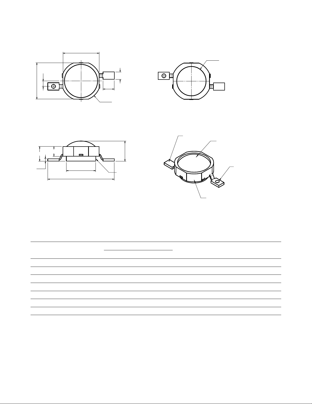
Package Dimensions
7.4
2.3
Ø 8.0
7.4
1.1
1.5
Ø 6.0
Metal Slug
Anode
Lead
Lens
Cathode
Lead
Body
Metal Slug
13.6
0.5
4.1 (ref:)
6.0
TOP VIEW
BOTTOM VIEW
3.0
2.0
Notes:
1. All dimensions in millimeters.
2. Metal slug is connected to anode for electrically non-isolated option.
Device Selection Guide (Tj = 25°C)
Color
Red ASMT-AR00 30.6 43.0 51.7 350 AllnGaP No
Amber ASMT-AA00 30.6 43.0 51.7 350 AllnGaP No
Blue ASMT-AB00 10.7 15.0 23.5 350 InGaN Yes
Green ASMT-AG00 51.7 65.0 87.4 350 InGaN Yes
Cool White ASMT-AW00 51.7 65.0 87.4 350 InGaN Yes
Neutral White ASMT-AN00 51.7 65.0 87.4 350 InGaN Yes
Warm White ASMT-AY00 51.7 60.0 87.4 350 InGaN Yes
Notes:
1. ΦV is the total luminous ux output as measured with an integrating sphere at 25ms mono pulse condition.
2. Flux tolerance is ±10%.
3. Electrically isolated metal slug option is also available. Please contact your Avago sale representative.
Part Number
Luminous Flux, Φ
[1,2]
V
(lm)
Test Current
(mA)
Dice
Technology
Electrically Isolated
Metal Slug Min. Typ. Max.
[3]
[3]
2
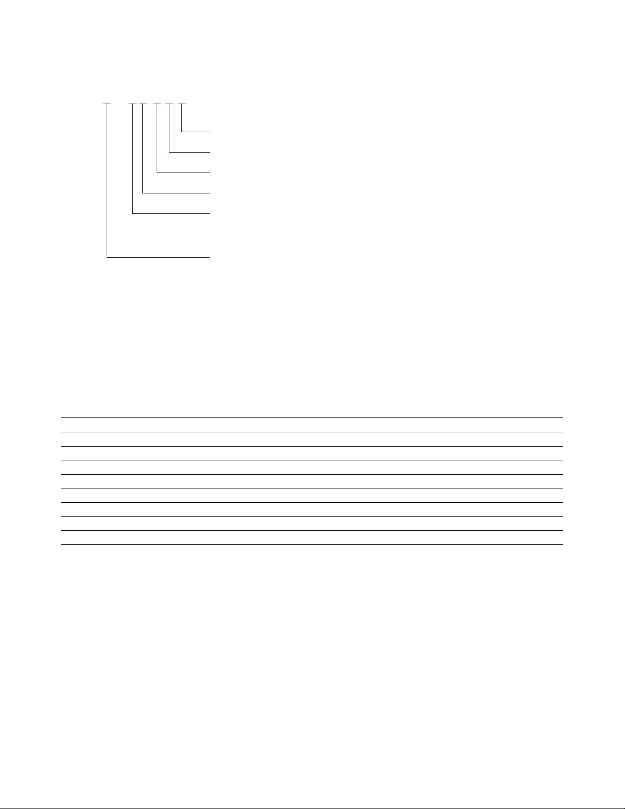
Part Numbering System
ASMT – A– A A x 00 – x x1 x
Note:
1. Please refer to Page 6 for selection details.
2 x3 x4
Packaging Option
Color Bin Selection
Maximum Flux Bin Selection
Minimum Flux Bin Selection
Dice Type
N – InGaN
A – AlInGaP
Color
R – Red
A – Amber
G – Green
B – Blue
W – Cool White
N – Neutral White
Y – Warm White
Absolute Maximum Ratings
Parameter AllnGaP InGaN Units
DC Forward Current
Peak Pulsing Current
Power Dissipation 1085 1400 mW
Reverse Voltage 5 5 V
LED Junction Temperature 125 135 °C
Operating Metal Slug Temperature Range at 350 mA -40 to +115 -40 to +120 °C
Storage Temperature Range -40 to +120 -40 to +120 °C
Soldering Temperature Refer to Figure 20
Notes:
1. Derate linearly based on Figure. 7 for AlInGaP and Figure. 17 for InGaN.
2. Pulse condition duty factor = 10%, Frequency = 1 kHz.
[1]
[2]
350 350 mA
500 500 mA
3

Optical Characteristics at 350 mA (TJ = 25°C)
Peak Wavelength,
λ
(nm)
PEAK
Part Number Color
ASMT-AR00 Red 635 625 130 48
ASMT-AA00 Amber 598 590 130 48
ASMT-AG00 Green 519 525 130 44
ASMT-AB00 Blue 460 470 130 12
Typ. Typ. Typ. Typ.
Correlated Color Temperature,
CCT (Kelvin)
Part Number Color
ASMT-AW00 Cool White 4500 10000 130 49
ASMT-AN00 Neutral White 3500 4500 130 49
ASMT-AY00 Warm White 2700 3500 130 45
Notes:
1. The dominant wavelength, lD, is derived from the CIE Chromaticity Diagram and represents the color of the device.
2. q½ is the o-axis angle where the luminous intensity is ½ the peak intensity.
Min. Max. Typ. Typ.
Dominant Wavelength,
[1]
λ
(nm)
D
Viewing Angle,
[2]
2θ
(°)
½
Viewing Angle,
[2]
2θ
(°)
½
Electrical Characteristic at 350 mA (TJ = 25°C)
Forward Voltage,
VF (Volts) at IF = 350mA
Dice Type
AllnGaP 1.9 2.4 3.1 10
InGaN 2.8 3.5 4.0 10
Notes:
1. Rθ
is Thermal Resistance from LED junction to metal slug.
j-ms
Min. Typ Max. Typ.
Thermal Resistance,
(°C/W)
[1]
Rθ
j-ms
Luminous Eciency
(lm/W)
Luminous Eciency
(lm/W)
4

0.0
0.1
0.2
0.3
0.4
0.5
0.6
0.7
0.8
0.9
1.0
380 430 480 530 580 630 680 730 780
WAVELENGTH - nm
RELATIVE INTENSITY
RED
AMBER
0
0.2
0.4
0.6
0.8
1
1.2
1.4
0 50 100 150 200 250 300 350 400 450 500
DC FORWARD CURRENT - mA
RELATIVE LUMINOUS FLUX
(NORMALIZED AT 350 mA)
0
50
100
150
200
250
300
350
400
450
500
0 0.5 1 1.5 2 2.5 3
FORWARD VOLTAGE - V
FORWARD CURRENT - mA
0
0.1
0.2
0.3
0.4
0.5
0.6
0.7
0.8
0.9
1
-90 -60 -30 0 30 60 90
ANGULAR DISPLACEMENT - DEGREES
NORMALIZED INTENSITY
AlInGaP
Figure 1. Relative Intensity vs. Wavelength. Figure 2. Relative Luminous Flux vs. Mono Pulse Current.
Figure 3. Forward Current vs. Forward Voltage. Figure 4. Radiation Pattern Red and Amber.
5
 Loading...