


ASW-09A4/EBR1
AUX ASW-09A4/EBR1, ASW-12B4/EE, ASW-H12A4/EI, ASW-09A4/EA, ASW-H12B4/EAR Service Manual
...
Service Manual
Contents
1.Important Notice.............................................1
2.Technical Specification................................2-9
3.Operation Details.....................................10-13
4.Wiring Diagram.......................................14-15
5.Troubleshooting Guide.............................16-23
6.Explosion View And Parts List..................24-31
7.Refrigeration Cycle Diagram........................32
8. Control Functions Exposition..................33-42
Split type Wall Mounted Air Conditioner
E series

This service manual is intended for use by individuals possessing adequate
backgrounds of electrical, electronic and mechanical experience. Any
attempt to repair the appliance may result in personal injury and property
damage. The manufacturer or seller cannot be responsible for the
interpretation of this information, nor can it assume any liability in
connection with its use.
The information, specifications and parameter are subject to change due
to technical modification or improvement without any prior notice. The
accurate specifications are presented on the nameplate label.
How to order spare parts
To have your order filled promptly and correctly, please furnish the
following information:
1. Model No. with Indoor or Outdoor
2. No. in the Explosion View
3. Part Name
4. The quantity you ordered
IMPORTANT NOTICE
1
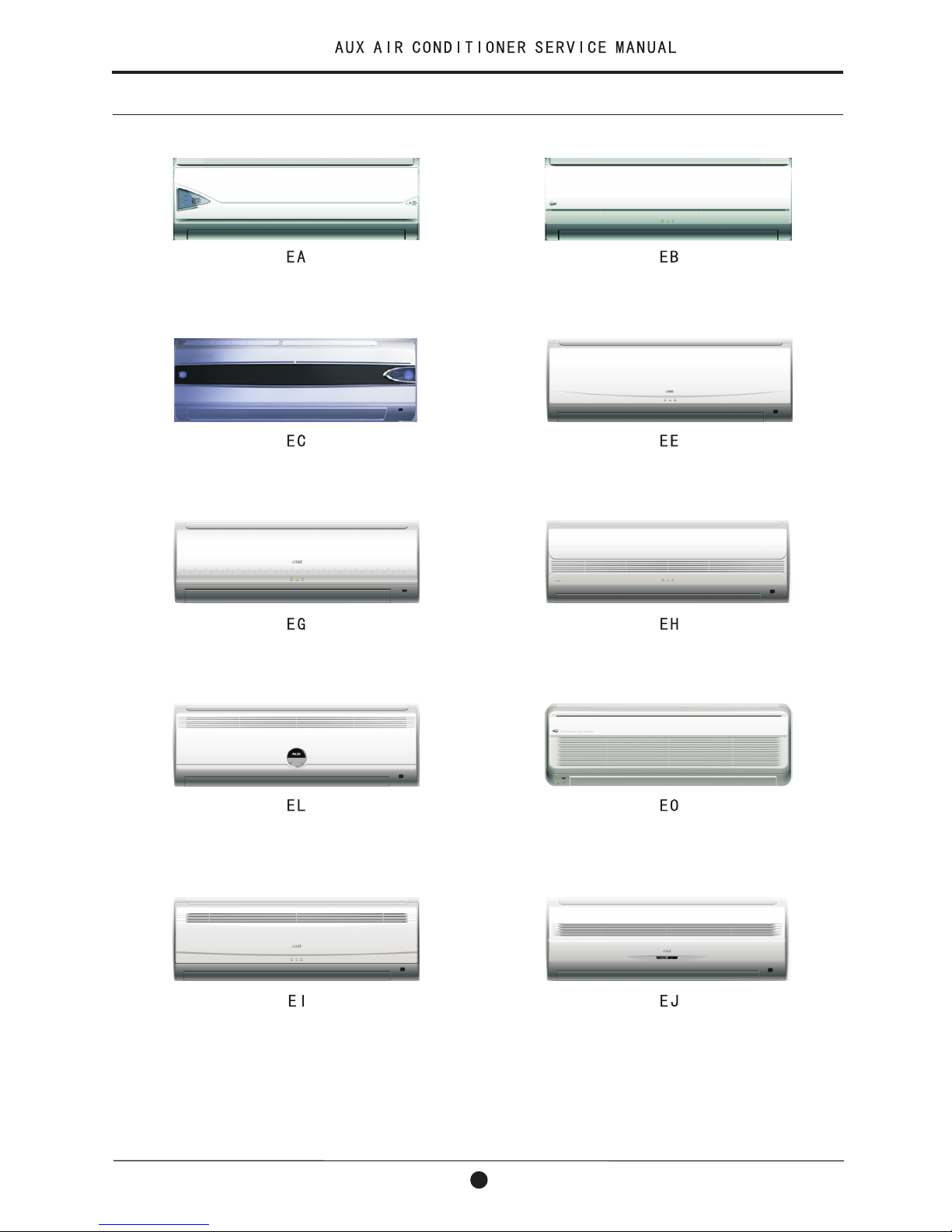
2-1 Appearance
2.Technical Specification
2
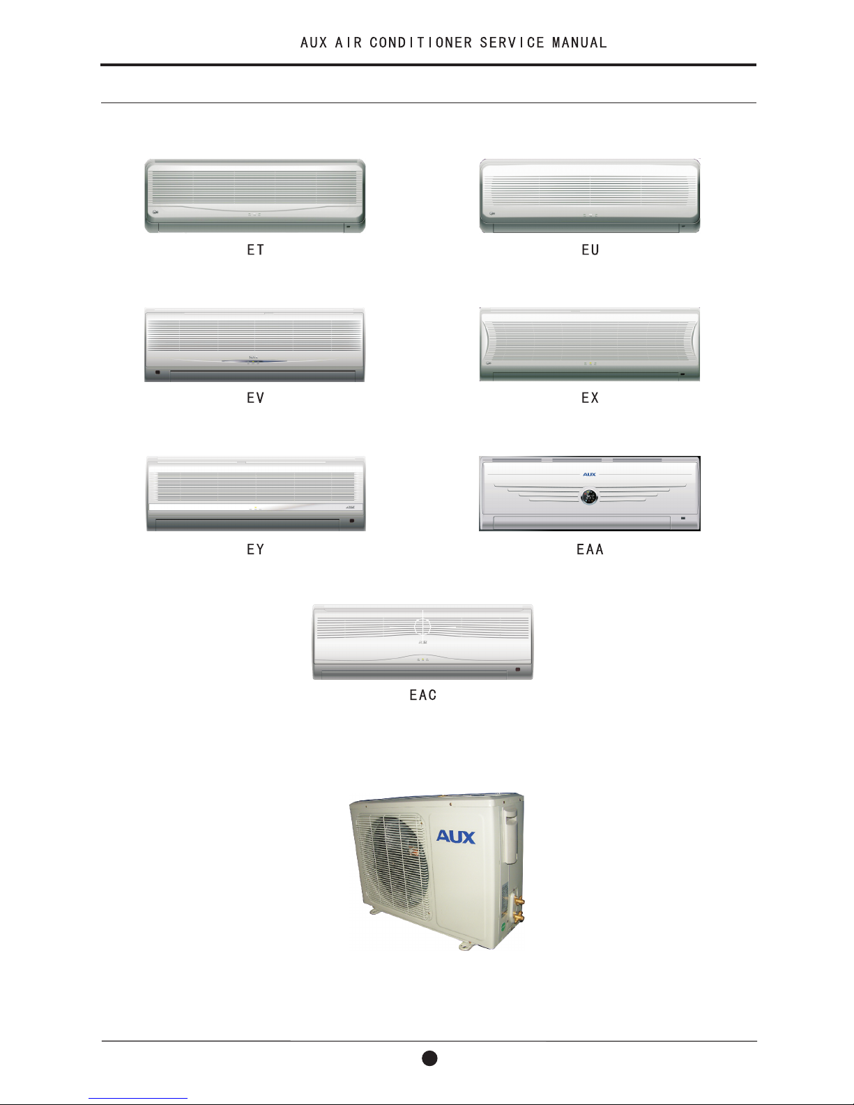
OUTDOOR UNIT
INDOOR UNIT
2-1 Appearance(continue)
2.Technical Specification
3
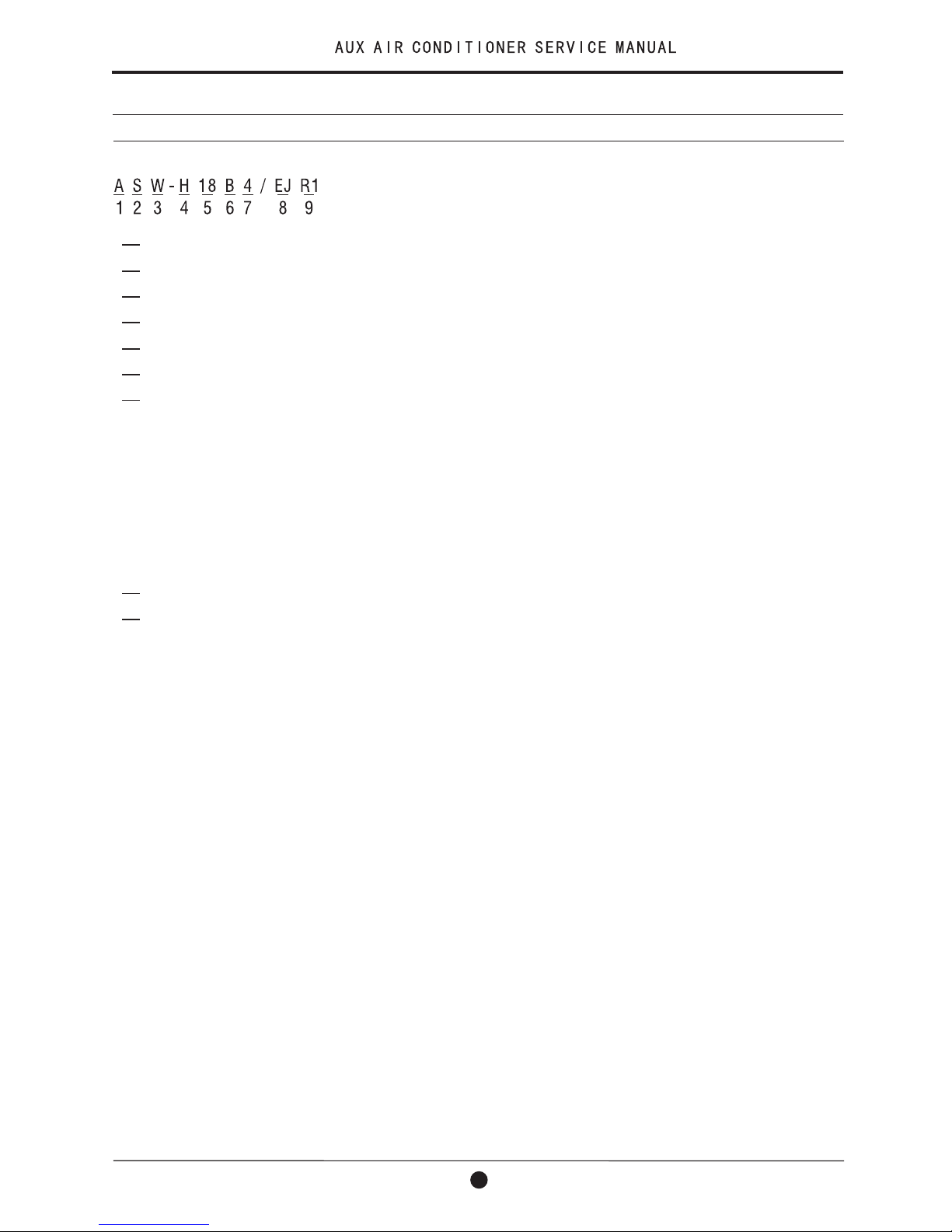
2-2 Nomenclature
1 AUX
2 Split-type
3 Wall mounted
4 Heat pump(only for heat pump)
5 Rated cooling capacity
6 The lever code of same cooling capacity
7 Power supply
1 for 220V~/50Hz
2 for 208V-230V~/60Hz
3 for 110V~/50Hz
4 for 220V-240V~/50Hz
5 for 380V-415V-3~/50Hz
6 for 380V-3~/60Hz
7 for 208V-230V~/50Hz
8 Type(For more details refer to 1-1)
9 Refrigerant
Default for R22
R for R407c
R1 for R410a
4
2.Technical Specification
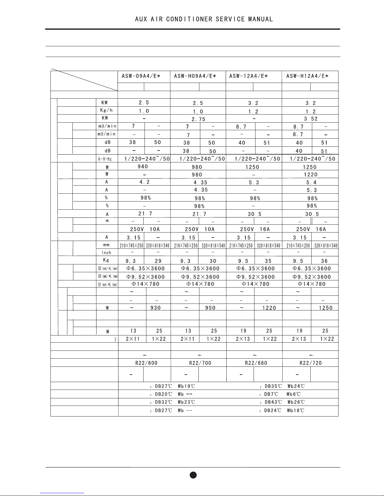
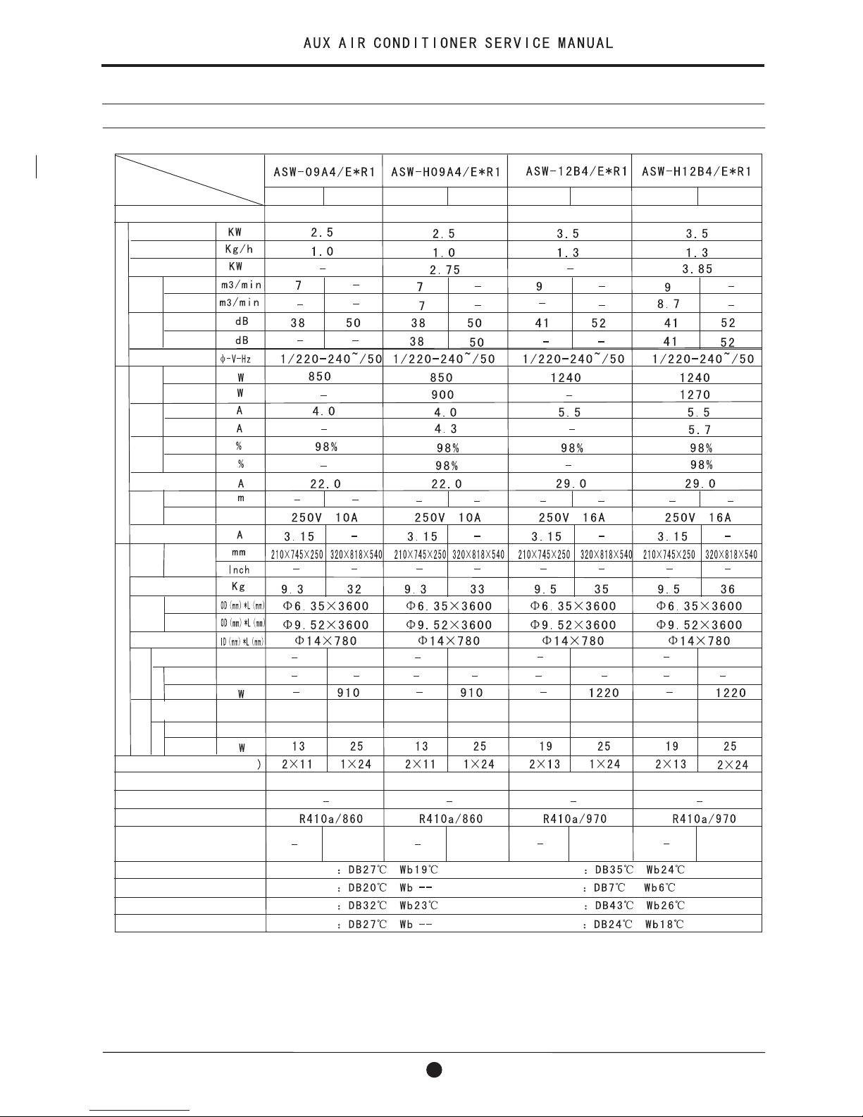
2-3 Product Technical Specification Diagram
Item
Model
Type
Performance
Cooling
Dehumidifying
Heating
Air Flow
Volume
Noise
Power supply
Rated
input
Rated
current
Input
factor
Starting current
Power
supply
cord
Length
Type
Fuse capacity
dimension
D*W*H
Net weight
Connection
pipe
Liquid
Gas
Drain pipe
Compressor
Type
MotorMotor
Type
Rated input
Rated input
Fan motor
Type
Type
Heat exchanger(row*line
Refrigerant controller
Freezed oil capacity
Refrigerant/Charge(g)
Protection equipment
Cooling test condition
Max.Cooling test condition
Heat ing test condition
Max.Heat ing test condition
Input
Dimension
Indoor Indoor Indoor Indoor
Outdoor Outdoor Outdoor Outdoor
Wall mounted Wall mounted Wall mounted Wall mounted
Rotary
Plastic-sealed
Iron-shell
Capillary
Inner
Indoor unit Outdoor unit
Indoor unit Outdoor unit
Indoor unit Outdoor unit
Indoor unit Outdoor unit
5
Cooling
Cooling
Cooling
Cooling
Cooling
Heating
Heating
Heating
Heating
Heating
Inner Inner Inner
Capillary Capillary Capillary
Rotary Rotary Rotary
Plastic-sealed Plastic-sealed Plastic-sealed
Through-flow
fan leaves
Through-flow
fan leaves
Axial-flow
fan leaves
Axial-flow
fan leaves
Through-flow
fan leaves
Through-flow
fan leaves
Axial-flow
fan leaves
Axial-flow
fan leaves
Iron-shell Iron-shell Iron-shell
2.Technical Specification
2-3 Product Technical Specification Diagram
2.Technical Specification
Item
Model
Type
Performance
Cooling
Dehumidifying
Heating
Air Flow
Volume
Noise
Power supply
Rated
input
Rated
current
Input
factor
Starting current
Power
supply
cord
Length
Type
Fuse capacity
dimension
D*W*H
Net weight
Connection
pipe
Liquid
Gas
Drain pipe
Compressor
Type
MotorMotor
Type
Rated input
Rated input
Fan motor
Type
Type
Heat exchanger(row*line
Refrigerant controller
Freezed oil capacity
Refrigerant/Charge(g)
Protection equipment
Cooling test condition
Max.Cooling test condition
Heat ing test condition
Max.Heat ing test condition
Input
Dimension
Indoor Indoor
Outdoor Outdoor
Wall mounted Wall mounted
Rotary
Plastic-sealed
Iron-shell
Capillary
Inner
Indoor unit Outdoor unit
Indoor unit Outdoor unit
Indoor unit Outdoor unit
Indoor unit Outdoor unit
Cooling
Cooling
Cooling
Cooling
Cooling
Heating
Heating
Heating
Heating
Heating
Inner
Capillary
Rotary
Plastic-sealed
Through-flow
fan leaves
Through-flow
fan leaves
Axial-flow
fan leaves
Axial-flow
fan leaves
Iron-shell
6
7
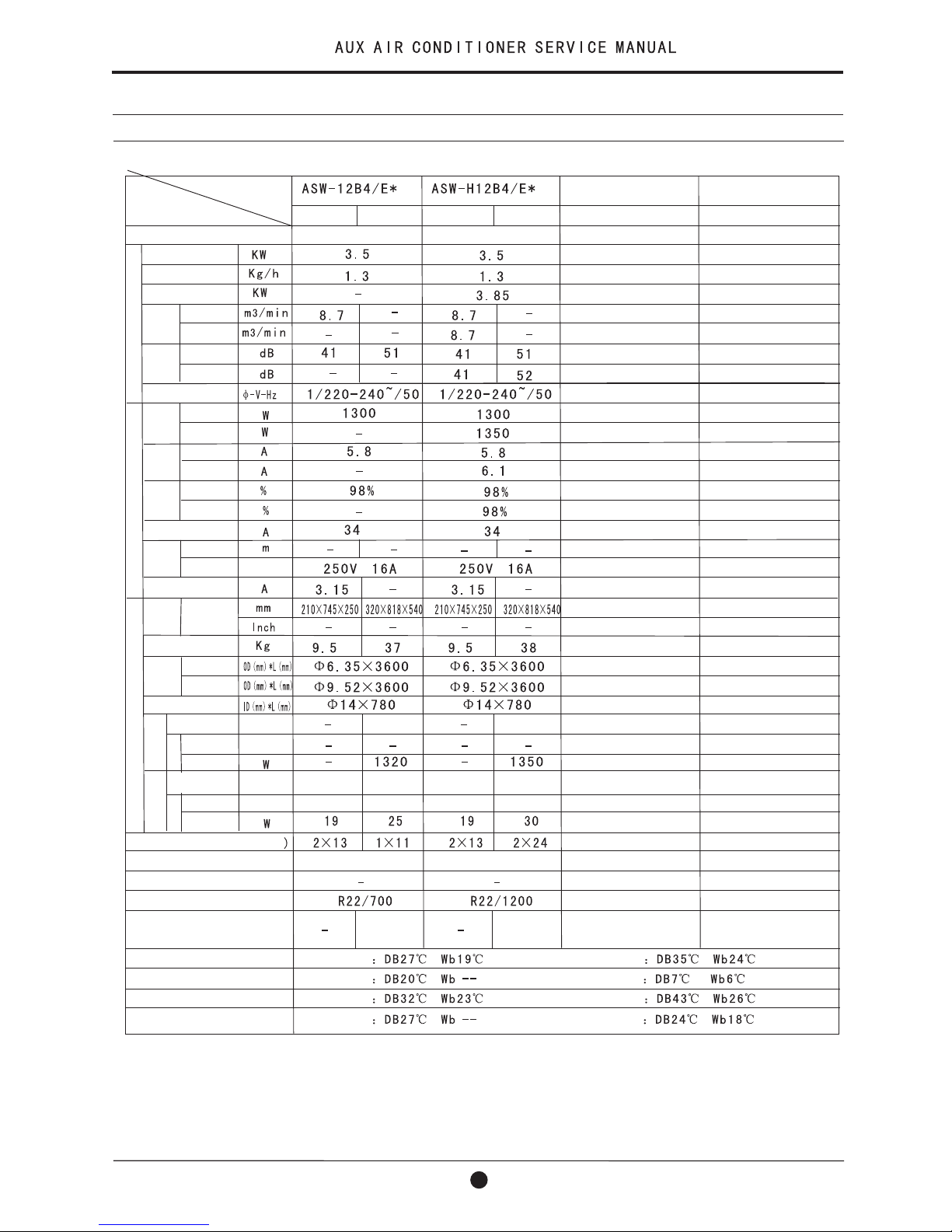
2-3 Product Technical Specification Diagram(continue)
Type
Performance
Cooling
Dehumidifying
Heating
Air Flow
Volume
Noise
Power supply
Rated
input
Rated
current
Input
factor
Starting current
Power
supply
cord
Length
Type
Fuse capacity
dimension
D*W*H
Net weight
Connection
pipe
Liquid
Gas
Drain pipe
Compressor
Type
MotorMotor
Type
Rated input
Rated input
Fan motor
Type
Type
Heat exchanger(row*line
Refrigerant controller
Freezed oil capacity
Refrigerant/Charge(g)
Protection equipment
Cooling test condition
Max.Cooling test condition
Heat ing test condition
Max.Heat ing test condition
Input
Dimension
Indoor Indoor Indoor Indoor
Outdoor Outdoor Outdoor Outdoor
Wall mounted Wall mounted Wall mounted Wall mounted
Rotary
Plastic-sealed
Iron-shell
Capillary
Indoor unit Outdoor unit
Indoor unit Outdoor unit
Indoor unit Outdoor unit
Indoor unit Outdoor unit
Cooling
Cooling
Cooling
Cooling
Cooling
Heating
Heating
Heating
Heating
Heating
Capillary Capillary Capillary
Rotary Rotary Rotary
Plastic-sealed Plastic-sealed Plastic-sealed
Through-flow
fan leaves
Through-flow
fan leaves
Axial-flow
fan leaves
Axial-flow
fan leaves
Through-flow
fan leaves
Through-flow
fan leaves
Axial-flow
fan leaves
Axial-flow
fan leaves
Iron-shell Iron-shell Iron-shell
Inner Inner Inner Inner
2.Technical Specification
Item
Model
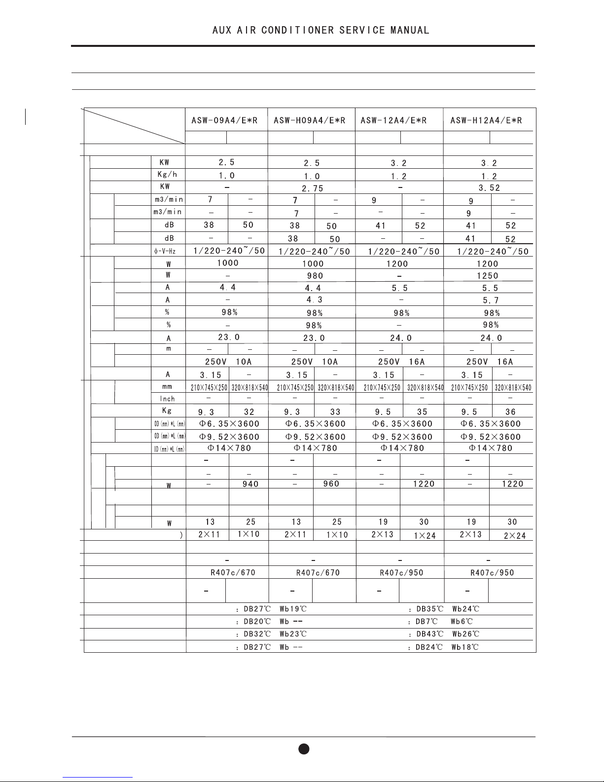
2-3 Product Technical Specification Diagram
2.Technical Specification
Item
Model
Type
Performance
Cooling
Dehumidifying
Heating
Air Flow
Volume
Noise
Power supply
Rated
input
Rated
current
Input
factor
Starting current
Power
supply
cord
Length
Type
Fuse capacity
dimension
D*W*H
Net weight
Connection
pipe
Liquid
Gas
Drain pipe
Compressor
Type
MotorMotor
Type
Rated input
Rated input
Fan motor
Type
Type
Heat exchanger(row*line
Refrigerant controller
Freezed oil capacity
Refrigerant/Charge(g)
Protection equipment
Cooling test condition
Max.Cooling test condition
Heat ing test condition
Max.Heat ing test condition
Input
Dimension
Indoor Indoor
Outdoor Outdoor
Wall mounted Wall mounted
Rotary
Plastic-sealed
Iron-shell
Capillary
Inner
Indoor unit Outdoor unit
Indoor unit Outdoor unit
Indoor unit Outdoor unit
Indoor unit Outdoor unit
Cooling
Cooling
Cooling
Cooling
Cooling
Heating
Heating
Heating
Heating
Heating
Inner
Capillary
Rotary
Plastic-sealed
Through-flow
fan leaves
Through-flow
fan leaves
Axial-flow
fan leaves
Axial-flow
fan leaves
Iron-shell
8
9
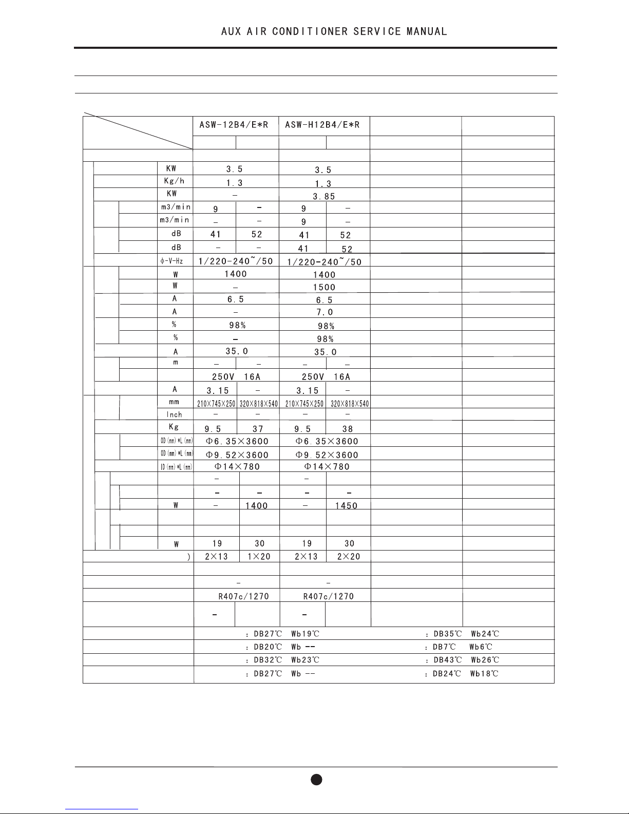
2-3 Product Technical Specification Diagram(continue)
Type
Performance
Cooling
Dehumidifying
Heating
Air Flow
Volume
Noise
Power supply
Rated
input
Rated
current
Input
factor
Starting current
Power
supply
cord
Length
Type
Fuse capacity
dimension
D*W*H
Net weight
Connection
pipe
Liquid
Gas
Drain pipe
Compressor
Type
MotorMotor
Type
Rated input
Rated input
Fan motor
Type
Type
Heat exchanger(row*line
Refrigerant controller
Freezed oil capacity
Refrigerant/Charge(g)
Protection equipment
Cooling test condition
Max.Cooling test condition
Heat ing test condition
Max.Heat ing test condition
Input
Dimension
Indoor Indoor Indoor Indoor
Outdoor Outdoor Outdoor Outdoor
Wall mounted Wall mounted Wall mounted Wall mounted
Rotary
Plastic-sealed
Iron-shell
Capillary
Indoor unit Outdoor unit
Indoor unit Outdoor unit
Indoor unit Outdoor unit
Indoor unit Outdoor unit
Cooling
Cooling
Cooling
Cooling
Cooling
Heating
Heating
Heating
Heating
Heating
Capillary Capillary Capillary
Rotary Rotary Rotary
Plastic-sealed Plastic-sealed Plastic-sealed
Through-flow
fan leaves
Through-flow
fan leaves
Axial-flow
fan leaves
Axial-flow
fan leaves
Through-flow
fan leaves
Through-flow
fan leaves
Axial-flow
fan leaves
Axial-flow
fan leaves
Iron-shell Iron-shell Iron-shell
Inner Inner Inner Inner
2.Technical Specification
Item
Model
3. Operation Details
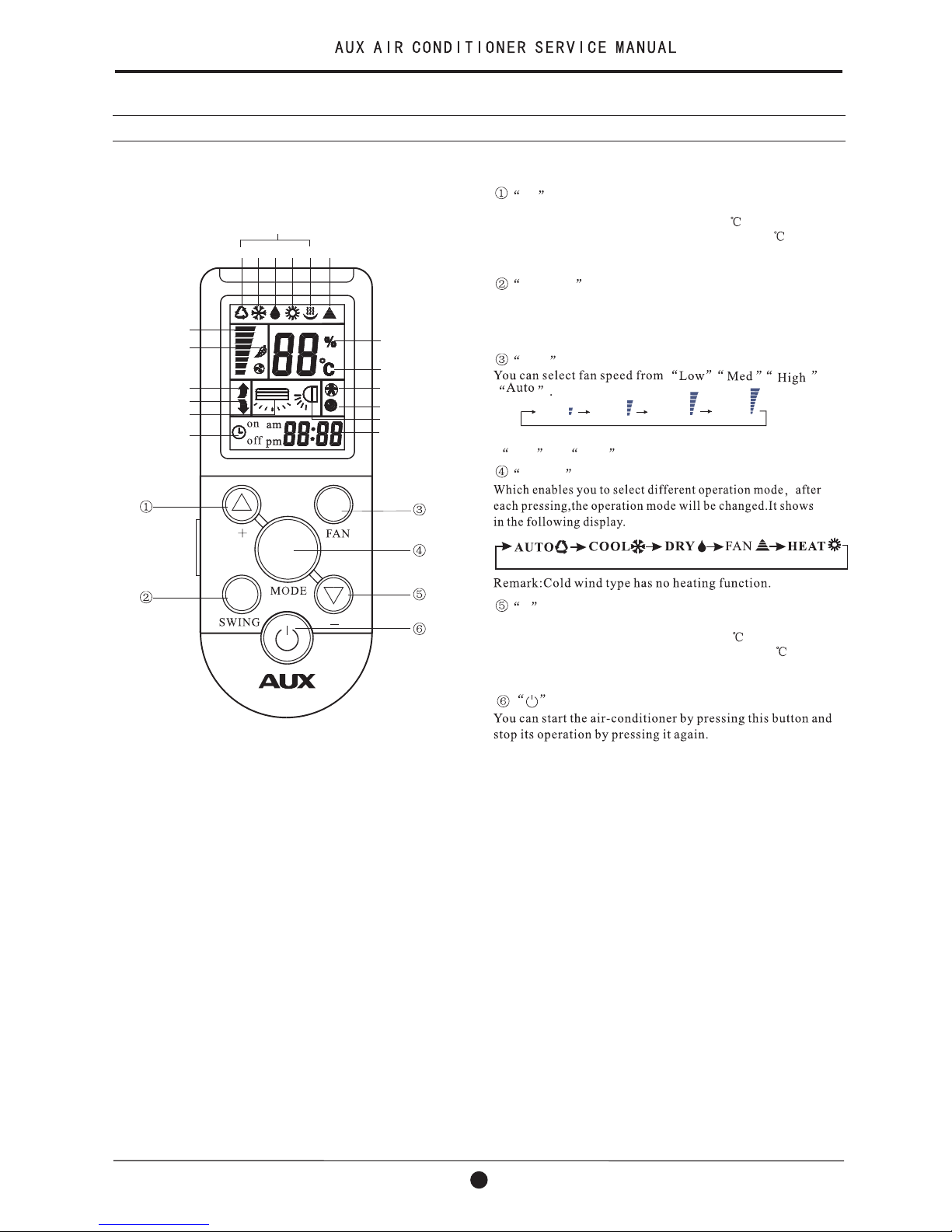
3-1 Remote Controller
10
+ button
This button can set room temperature.
Press it once ,the temperature increases 1 .Press it continuously, the temperature increases at the speed of 4 /s.
This function is invalid when the appliance at the Fan and
Auto mode.
Press the button, the horizontal airflow direction plate can
adjust automatically. When you have the desired wind
direction, please press it again, the airflow direction plate
will stop at the situation.
SWING button
FAN button
Remark: The floor standing type select fan speed only from
Low to High .
- button
MODE button
This button can set room temperature.
Press it once ,the temperature decreases 1 .Press it continuously, the temperature decreases at the speed of 4 /s.
This function is invalid when the appliance at the Fan and
Auto mode.
Button
High
Low
Auto
Med
The closing state of remote controller:
Auto
Humidity display
Temperature display
Sleep display
Timer/Clock display
Fan speed display
Power display
Quiet display
Cool Dry Heat Wet
Emission display
Mode display
Anion function display
Feeling display
Up/Down wind display
Left/Right wind display
Timer On/Off display
HEALTH
SLEEP
HUMIDITY
FEELING/LOUVER
POWER
/QUIET
TIMER/CLOCK
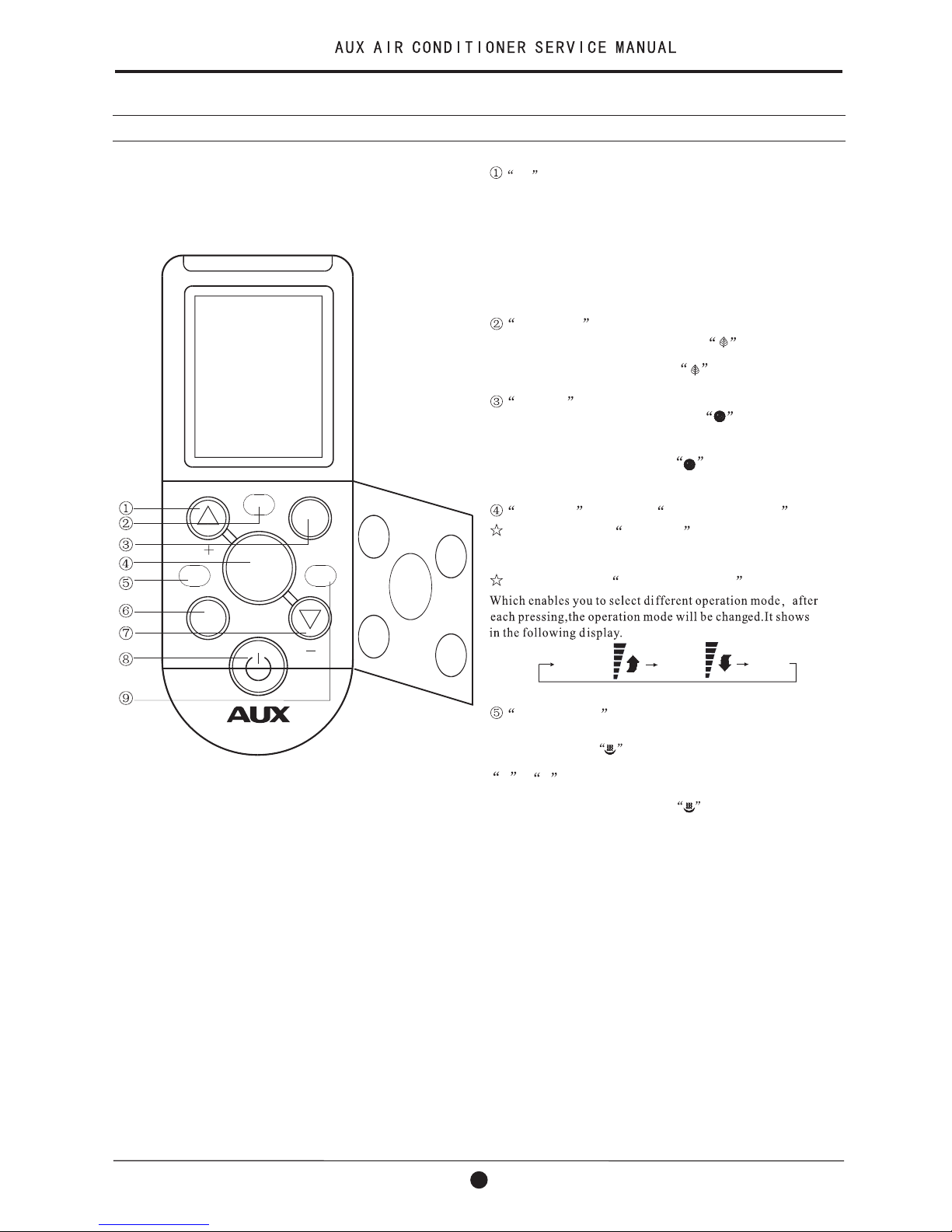
The opening state of remote controller:
+ button
This button not only can adjust clock time and the timer time
but also can set room humidity.
Adjusting clock time and timer time
Press it once ,the time increases one minute. Press it for 1 to
3 seconds, time display will increase at the speed of 2min/s.
For 3 to 5 seconds, it will increase at the speed of 10min/s.
For more than 5 seconds, it will increase at the speed of 10min/s.
Setting room temperature and room humidity
Press it once ,the humidity increases 5%.
HEALTH button
Press this button ,the LCD shows the symbol, the anion
emission function of the air conditioner is started.
Press the button once again, The symbol disappears, the
function is cancelled at the same time.
SLEEP button
Press this button ,the LCD shows the symbol, the sleeping
function of the air conditioner is started. After 7 hours of setting
this function ,the air conditioner will beoff automatically.
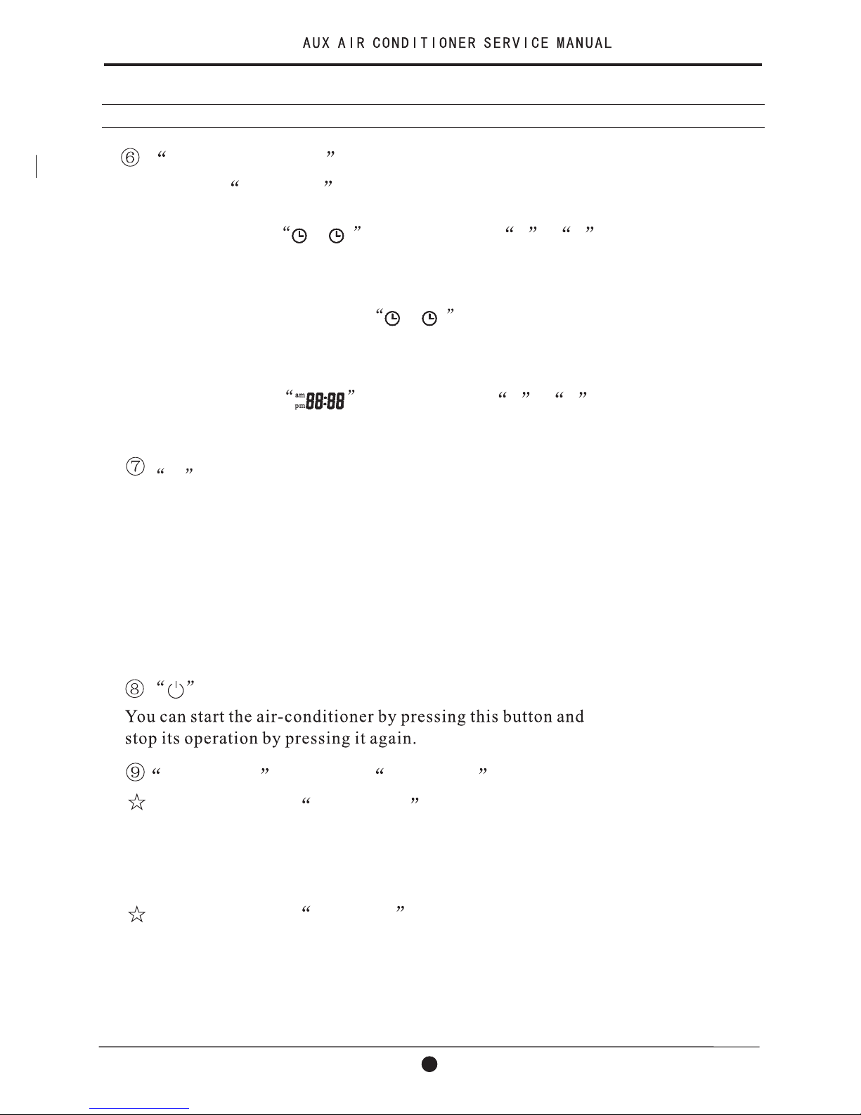
POWER button or POWER/QUIET button
POWER
QUIT
QUIET
HUMIDITY button
Only under the mode of Heat and Fan, Press this button once ,
the LCD shows the symbol, the wetting function of the air
conditioner is started. The initial humidity is 60%. Press the
+ or - button once ,the humidity increases or decreases
5%. The setting range is 30%~60%.
Press the button once again, The symbol disappears, the
function is cancelled at the same time.
Press the button once again, The symbol disappears, the
function is cancelled at the same time.
This function is invalid when the appliance under the Fan mode.
This function is only suitable for frequency variable appliance.
When it displays POWER button:
When it displays POWER/QUIET button :
Press this button, the fan speed reach the highest , press it again
it resume the foregoing fan speed.
3. Operation Details
3-1 Remote Controller(continue)
11
3. Operation Details
3-2 Operation Method
Press the button once more, The symbol disappears,
the function is cancelled at the same time.
Adjusting the clock time
/
off
on
Press this button in 5 seconds Under the state of no timer setting ,
the LCD flickers the symbol. Press the + or -
button to set the timer time. After finishing it, press this button
again in 10 seconds to affirm. If not, this operation is invalid.
- button
Adjusting clock time and timer time
Press it once ,the time decreases one minute. Press it for 1 to
3 seconds, time display will decrease at the speed of 2min/s.
For 3 to 5 seconds, it will decrease at the speed of 10min/s.
For more than 5 seconds, it will decrease at the speed of 10min/s.
Setting room temperature and room humidity
Press it once ,the humidity decreases 5%.
button
Press this button can be used to set the feeling function.
The LCD shows the actual room temperature when the function
set and it shows the setting temperature when the function cancelled.
This function is invalid when the appliance at the Fan mode.
FEELING button or LOUVER button
When it displays FEELING button:
When it displays LOUVER button:
Press this button, the vertical wind direction vanes can rotate automatically, when you have the desired horizontal wind direction, press it
again, the vertical wind direction vanes will be stopped at the situation
of your choice.
TIMER/CLOCK button
Setting the ON/OFF timer time
When remote controller is at the on/off state, Press this button ,
the LCD flickers the symbol. Press the + or -
button to set the timer time. After finishing it, press this button
again in 10 seconds to affirm. If the setting time is the same as
the current time, this setting is invalid.
/
off
on
This button not only can adjust clock time and the timer time
but also can set room humidity.
1
12
3. Operation Details
3-2 Operation Method(continue)
3.Press the + or - button, you can set the temperature
range from 16 to 32 .
4.Press the FAN button, you can select fan speed from
Low , Med , High , Auto .
1.
2.
2.Press the + or - button, you can set the temperature
range from 16 to 32 .
3.Press the FAN button, you can select fan speed from
Low , Med , High , Auto .
2.Press the FAN button, you can select fan speed from
Low , Med , High .
1
13
 Loading...