

Page 1
ZoningZoning
Zoning
ZoningZoning
Design GuideDesign Guide
Design Guide
Design GuideDesign Guide
Page 2

Zone
Zone
8500 NW River Park Drive • Parkville , MO 64152
PH: (816) 505-1100 • FX: (816) 505-1101 • E-mail: mail@wattmaster.com
Visit our website at www.wattmaster.com
Form: WM-AZA-ZDG-01B Copyright 2001 WattMaster Controls, Inc.
Auto-Zone & System Manager are registered trademarks of WattMaster Controls, Inc.
WattMaster Controls assumes no responsibility for errors, or omissions.
This document is subject to change without notice. All rights reserved.
Page 3

Table Of Contents
How Auto-Zone Works ..........................................................................................................5
Why Should I Use Auto-Zone?..............................................................................................6
What Is Unique About Auto-Zone? ....................................................................................6-8
Zoning Systems Versus True VAV Systems .......................................................................... 9
Basics Of Designing A Zoning System................................................................................ 10
Design Considerations ................................................................................................... 11-12
Zoning Design Procedures.............................................................................................13-21
System Installation .........................................................................................................22-26
Application Notes ................................................................................................................27
Table Of Figures & Tables
Figure 1-1: Auto-Zone Plus System Overview .................................................................... 5
Figure 1-2: Zones Affected By Outdoor Load...................................................................13
Figure 1-3: Zone Layout With External Zones Only ......................................................... .14
Figure 1-4: Zones With North And South Exposures ....................................................... .14
Figure 1-5: Zoning And Constant Volume Units ................................................................14
Figure 1-6: Round Bypass Damper.................................................................................. .16
Figure 1-7: Rectangular Bypass Damper & Kit ................................................................ .16
Figure 1-8 Preferred Sensor Location ..............................................................................1 7
Figure 1-9: Acceptable Sensor Location ........................................................................... 17
Figure 1-10: Least Desirable Sensor Location .................................................................... 17
Figure 1-11: Pressure Dependent Damper .........................................................................1 8
Figure 1-12: Pressure Independent Damper.......................................................................1 8
Figure 1-13: WattMaster Communications Wire ................................................................. 23
Figure 1-14: Auto-Zone Basic System Communications Loop Wiring ................................2 4
Figure 1-15: Auto-Zone Plus System Communications Loop Wiring .................................. 24
Figure 1-16: Transformer & Wire Sizing Considerations.....................................................26
Table 1-1: Round Damper Selection Data.......................................................................... 19
Table 1-2: Rectangular Damper Selection Data .................................................................2 0
Page 4

Page 5
How Auto-Zone Works
Zoning Design Guide
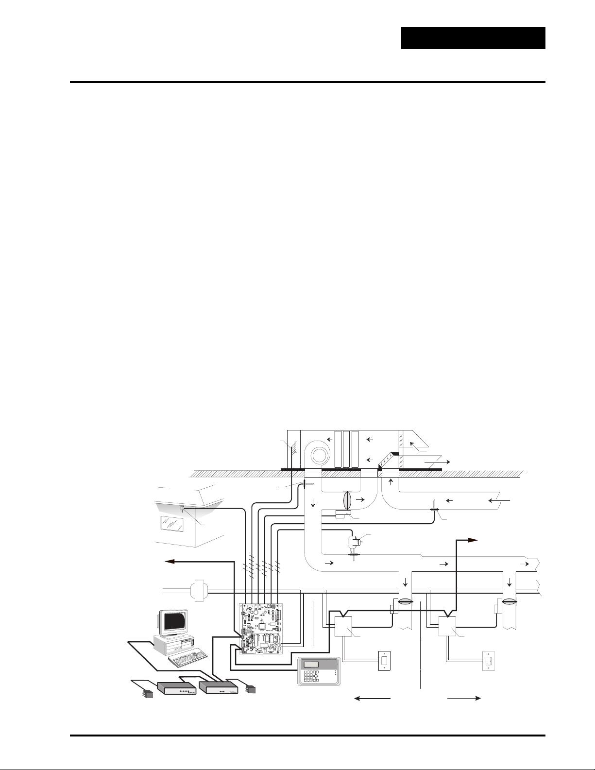
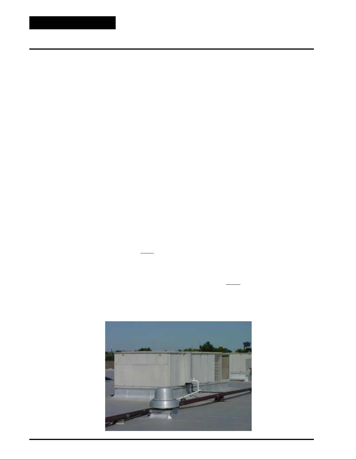
The Auto-Zone control system converts single-zone
constant volume rooftop packaged or split system
HVAC units into variable air volume/variable temperature multiple zone systems. The microprocessor based
Zone Manager calculates the heating and cooling requirements for each zone based on real time information received from each Zone Controller/Damper. The
Zone Manager then directs the HVAC unit to provide
the appropriate amount of heating, cooling, and ventilation to satisfy each zone’s requirements. A bypass
damper controlled, by a static air pressure sensor, modulates a bypass damper to maintain constant duct pressure.
The Auto-Zone system uses a unique 3 tier approach to
controlling the system:
• Voting Zones
• System Demand
• Priority
This 3 tier system works in an integrated fashion to
maintain proper control of the equipment and effective
control of comfort in the zone.
First the zone must initiate a vote to the HVAC unit.
This occurs when a zone becomes more than 1 degree
off setpoint. At this time a vote is placed for heating or
cooling. Next the controller evaluates the total cooling
demand or heating demand within the entire building
to see which requirement is more critical. Finally, the
system looks for any priority conditions, which would
take precedence over other zones. All three of these
elements working together provide accurate and stable
control of comfort.
Additional control features are taken into account to
provide a very effective control of the system. Some of
these include priority override, supply air temperature
limits, outside air temperature lockouts, and min./max.
control over damper position.
Substantial savings can be realized using the Auto-Zone
Zoning system instead of having to install multiple rooftop units to accommodate multiple zone requirements.
The Auto-Zone Zoning system is versatile and can be
used with any packaged roof top unit or split system. It
controls a variety of terminal unit functions including
single duct pressure dependent, pressure independent,
series fan and parallel fan terminals.
CONNECT TO OTHER
ZONE MANAGERS
120/9 VAC
TRANSFORMER
AVOID
DIRECT
SUNLIGHT
NETWORK COMM LOOP
AC LINE
VOLTAGE
COMPUTER
(OPTIONAL)
RemoteLink
CONTROLS
REMOTE LINK
(OPTIONAL MODEM)
2 CONDUCTOR
24 GA.
OUTSIDE AIR
SENSOR
24 VAC
GROUND
COMMLINKII
CONTROLS
COMM LINK II
INTERFACE
( OPTIONAL )
CONTROL CABLE
SUPPLY AIR
TEMPERATURE
SENSOR
2 CONDUCTOR
ZONE MANAGER
LOCAL COMM LOOP
120/24 VAC
TRANSFORMER
24 GA.
SYSTEM MANAGER
FAN
0
1
4
7
c.
e
D
*
H
C
F
E
O
I
A
L
O
MIXED
T
T
L
I
I
AIR
E
N
N
R
G
G
OUTSIDE AIR
EXHAUST AIR
RETURN AIR
MODULATING
3 CONDUCTOR
24 GA.
LO
BYPASS DAMPER
STATIC PRESSURE SENSOR
& PICKUP TUBE
HI
2 CONDUCTOR
24 GA.
RETURN AIR SENSOR
CONNECT TO OTHER
ZONE CONTROLLERS
OR CV UNITS
SUPPLY AIR DUCT
MODULATING
DAMPER
ZONE
CONTROLLER
V
C
e
n
o
Z
-
o
t
u
A
N
O
M
M
P
8
3
:
2
0
8
9
/
0
2
/
7
D
E
I
P
U
C
C
O
S
M
R
A
L
A
O
N
SYSTEM
MANAGER
m
r
la
A
sc
E
u
n
e
M
2
3
n
o
ti
a
ic
n
u
m
m
o
C
e
d
i
r
r
e
v
O
6
5
8
9
s
u
in
M
r
te
n
E
r
a
le
C
0
.
C
N
I
S
L
O
R
T
N
O
C
R
E
T
S
A
M
T
T
A
W
ZONE 1
TEMPERATURE SENSOR
MODULATING
DAMPER
ZONE
CONTROLLER
WARMER
NORMAL
COOLER
OVR
ZONE 2
TEMPERATURE SENSOR
W/OVERRIDE AND SETPOINT ADJUST
UP TO 16 ZONES
Figure 1-1: Auto-Zone Plus System Overview
Auto-Zone Systems 5
Page 6
Zoning Design Guide
Why Should I Use Auto-Zone?
Auto-Zone is a proven system with a long history of
successful installations. Our systems have been refined
over the years with the help of feedback from people in
the field who work and live with these systems on a
daily basis. Our success is greatly due to the fact that
we have implemented changes and enhancements based
on real world experience not from tinkering with equipment in an isolated lab environment. This real world
approach provides engineers, contractors, and end users with a zone control system that is efficient, reliable,
and most importantly, keeps the customers comfortable!
What Is Unique About Auto-Zone?
Auto-Zone is unique because it has many features not
found on other systems. These features include
Non-Proprietary Design
Auto-Zone will work on any manufacturers HVAC
equipment that will accept a standard thermostat connection. This protects the end user from being locked in
to one source for service and support. In addition, AutoZone Systems include very comprehensive documentation, which was written in a format specifically for a
“non-controls technician”. Because the manuals are so
user friendly, it prevents the end user from being
“locked-in” to one contractor for service. Any new contractor needs only a copy of the system manual to have
as much technical information as any previous contractor.
Pre-Engineered Software
System design, software, and documentation has already
been done for you. This eliminates the costly expense
usually associated with conventional DDC systems,
making the Auto-Zone system more competitive and
easier to install and operate.
One System for Zoned or Single Zone
Systems
Not only does Auto-Zone provide a networked zone
control system for one or multiple zoned HVAC units,
you can also connect individual single zone units to the
system eliminating the need to use programmable thermostats.
Easy to Configure
Since Auto-Zone components are grouped into packages, configuring a system has been simplified. This
reduces the chance of ordering errors and makes system layout effortless!
User Friendly Set Up
Since the Auto-Zone comes with menu driven, fill in
the blank programming, system setup is simple. The
system manual takes you step by step through the set
up process. Default parameter values are programmed
into permanent memory so the system can be operational at start-up. Specialized training is not required.
6 Auto-Zone Systems
Page 7

Zoning Design Guide
True Network Communications
The Auto-Zone uses a three wire, RS-485 loop for communication between all controllers in the system. This
provides a very reliable form of communication with
flexibility of installation. The loop can be wired in a
“daisy chain” or “star” configuration. Many other zoning systems utilize “home run” wiring that requires all
communication cables to be brought back to a central
point adding additional cost to the project and complicating wiring.
High Integrity Communications
Many communicating control systems are susceptible
to electrical interference. One major manufacturer of
zoning systems recommends that their communication
cable should not be strapped to conduit because of potential interference. The Auto-Zone Systems have a
communication bus that is almost immune to any noise
problems that may be found in most commercial facilities.
Microprocessor Controllers
All controllers in the Auto-Zone have an on board
microprocessor. This is what gives the Auto-Zone its
powerful features and capabilities not found in other
systems.
Stand Alone Systems
All Auto-Zone Systems are true stand-alone and do not
require a computer to operate. Unit controllers maintain their own 7 day time clock, 365 day holiday scheduling, and setpoints within each controller.
Menu Driven Operators’ Interface
All Auto-Zone systems have an operators’ keypad and
display terminal. This gives you access to system status and parameter values without the need for a computer. The 4 line by 20 character display is backlighted
making it easy to read even in low light environments.
Menu driven programming makes the system extremely
user friendly. In addition, the interface panel is password protected to keep unauthorized users from accessing the system.
Communications Via Optional Modem
The Remote Link is used for achieving remote communications with the Auto-Zone system. It connects to the
CommLink II communications interface and a local
phone line. With the Remote Link, the Auto-Zone system can be monitored and controlled from a remote location, using a computer and the ZoneView AZ or Plus
software packages.
Memory Backup
Instead of batteries, which have to be replaced, AutoZone utilizes super capacitors to provide power for
memory backup during power outages. The major advantages to this approach is that super capacitors are
more reliable than batteries and they recharge in a matter of seconds instead of hours. T ypical memory backup
is good for a minimum of 10 days.
Modulating, Heavy Duty Actuators with
Real Time Feedback
All Auto-Zone actuators utilize true modulating control unlike many systems, which are two position. This
gives the system-improved control, which translates, to
better comfort levels. Our actuators are also rated for
2-½ million cycles, making our actuators some of the
most reliable in the industry. One other critical feature
is the real time feedback. Many other systems have no
feedback at all. They blindly estimate the travel time of
their actuator, which, in the real world, is not a very
repeatable estimate. To help correct the problems inherent with this approach, they recycle all the actuators
in the system once or twice a day . They may save a few
dollars by not including feedback but they sacrifice system performance. Not so with Auto-Zone.
Commercial Grade – Insulated Round
Zone Dampers
Auto-Zone only uses commercial grade zone dampers,
not cheap, flimsy, “light commercial” or “residential”
style dampers like many other manufacturers. Our round
damper is ARI certified and comes from the factory
fully insulated. Why? When many zone dampers are
installed they are improperly insulated or not insulated
at all. This can cause problems with the damper “sweating” from condensation. With factory insulated zone
dampers, we eliminate a common problem for the contractor while insuring the end user will not have problems with condensation dripping down onto the ceiling.
Auto-Zone Systems 7
Page 8
Zoning Design Guide
What Is Unique About Auto-Zone?
Rectangular Dampers
Auto-Zone uses only top of the line, aluminum air foil
rectangular control dampers. No other zone system on
the market today utilizes a damper of this quality and
performance!
Patented Flush Mount Room Sensors
Our flush mount room sensors are so unique, they are
patented (U.S. Patent No. 4,659,236). Even though part
of the sensor is recessed into the wall to provide an
attractive yet tamper proof flush mounting, internal wall
temperatures do not influence the sensor. A special plate
on the face of the sensor accurately senses space temperature. Even though the attractive off white plastic
housing is a preferred color, the sensor housing can be
painted or wallpapered to blend with room decor without affecting sensor performance. The sensors are offered in four different configurations:
• Sensor
• Sensor w/override
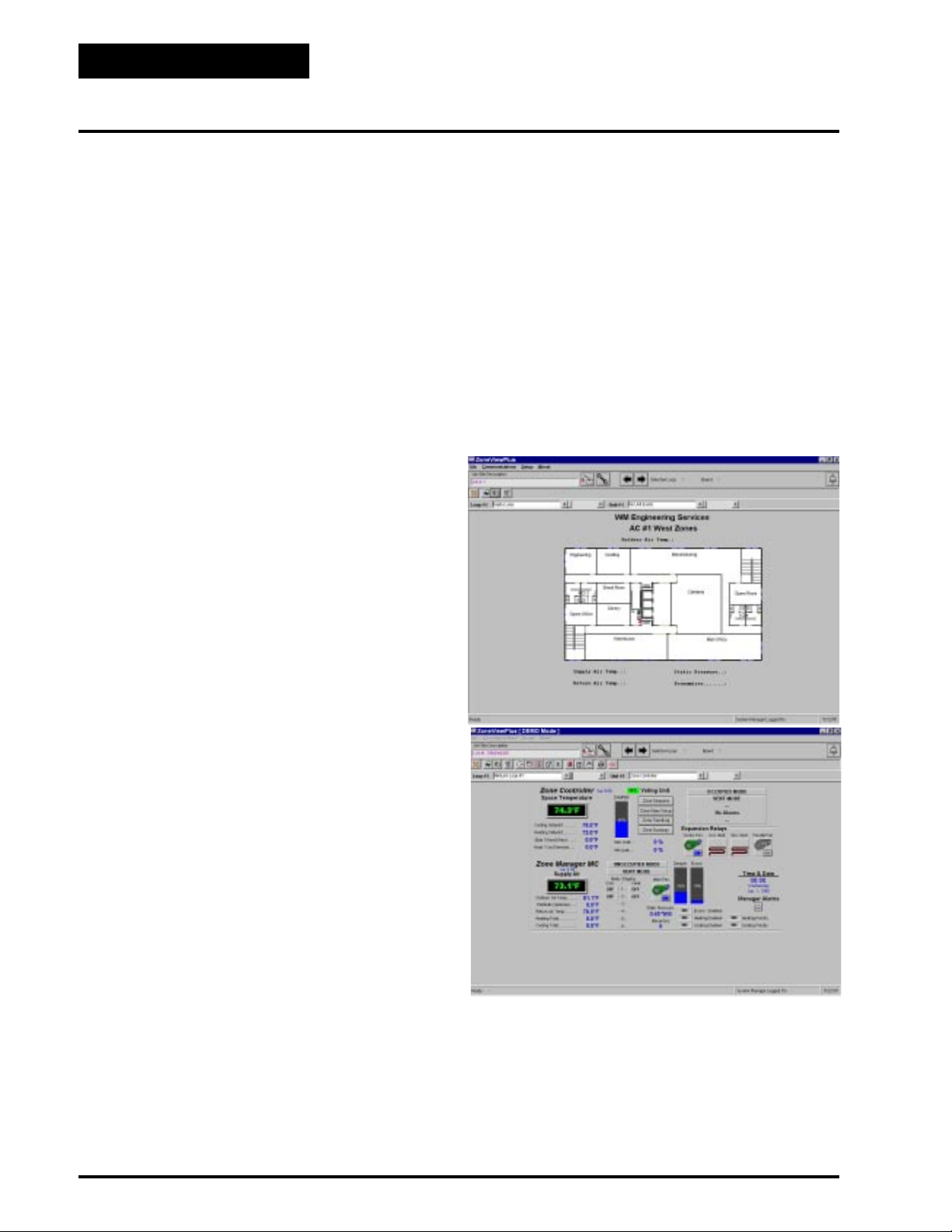
hundreds. ZoneView is not copy protected so it can be
installed on multiple PC’s’ without additional expense.
Just some of its many features include but are not limited to:
• Pre-designed status screens for all controllers
• Alarm dial out capability
• Programming of all system parameters
• Trend logging to Excel™ spreadsheets
• Alarm Handling
• Custom graphics capability
• Sensor w/setpoint adjustment
• Sensor w/setpoint adjustment & override
Modular Connections
Many Auto-Zone auxiliary devices are connected to the
controllers via modular plugs like the ones used on telephones. This simplifies installation and eliminates the
possibility of wiring errors. The devices, which utilize
this method, are damper actuators for zone and bypass
control, auxiliary relay boards, and static pressure/air
flow sensors. There is one interesting side note about
the auxiliary relay board and airflow sensors. These
devices are typically used on the zone controllers in the
Auto-Zone Basic & Plus systems. When the system is
powered up, it automatically looks to see if these devices are connected to the controller. If they are, the
controller automatically reconfigures itself to utilize
these devices and activates the appropriate set up screens
back at the operators interface. Pretty neat don’t you
think!
FREE! Windows™ Graphics Software
Each Auto-Zone system can be monitored on site or
remotely using a PC and our ZoneView Plus™ Windows 98 software. This full-featured package is very
user friendly and can be used to monitor one system or
Open Protocol System
Auto-Zone is an open protocol based system allowing
other manufacturers to develop direct interfaces to the
communications loop. This gives you the ability to integrate the Auto-Zone system into products from other
vendors. Our engineering staff will be glad to assist any
vendor in this process.
8 Auto-Zone Systems
Page 9

Zoning Design Guide
Zoning Systems Versus True VAV Systems
General
Even though there are some similarities between zone
control systems and Variable Air Volume (VAV) systems, there are some major differences. In many cases
systems will be called VAV when in fact they are really
a zoning system or are referred to as a zoning system
when they are really a VAV system. Always make sure
that you do not try to adapt a zoning system to a VAV
design system. Understanding the differences will help
you to prevent misapplication of the Auto-Zone zoning
system. In the paragraphs that follow we will try to explain the differences, advantages and disadvantages of
each and explain their operation.
V AV Systems
These systems consist of an HVAC unit that is generally a cooling only unit and VAV terminal units located
in the downstream ductwork that are used to control
the amount of constant temperature air delivered to the
various building zones. Sometimes the HV AC unit may
have gas or electric heat, but it is typically sized and
applied for morning warm-up purposes. The HV AC unit
is designed to vary the volume of air that is supplied to
the duct system by using either inlet vanes or an electronic variable frequency drive. These devices modulate to control the air flow through the supply fan in
response to the static pressure in the duct system. VAV
systems typically use high velocity VAV terminal units
to distribute the air to the zones. As the various VAV
terminal units in the different zones open and close to
supply the constant temperature air to the spaces, the
HVAC unit varies the volume of constant temperature
air based on the static pressure in the ductwork. The
HV AC unit is designed to maintain a constant cold supply air temperature regardless of the air flow volume in
the system. The HVAC unit cycles it’s cooling stages
to maintain a constant predetermined supply air temperature. It typically runs continuously based on a schedule. For perimeter zones requiring heat, reheat coils
(electric or hot water) located in the terminal units are
used to supply heated air to the space. Many times fan
powered terminal boxes are used and in many cases
also incorporate electric or hot water heating coils to
provide perimeter zone heating. In summary a true V AV
system uses a variable volume fan supplying constant
temperature air to the system with variable volume terminal units used to control the volume of constant temperature air delivered to the space. Generally these systems use pressure independent damper control.
Auto Zone Systems
The Auto-Zone zoning system is completely different
in operation and design from the VAV system previously discussed. One of the major differences between
the zoning system and a true VAV system is that the
HVAC unit used on a zoning system utilizes a constant
volume fan. Air volume control of the zoning system is
achieved by bypassing air from the HVAC unit supply
duct back into the HVAC unit return air duct on the unit
inlet. This bypass air is controlled based on a static pressure sensor located in the supply air duct downstream
of the unit supply air discharge. The bypass damper
modulates open and closed based on the static pressure
in the duct. The temperature at the HV AC unit dischar ge
varies in relation to the demand from the zones. Typically the HVAC units used for the zoning system will
have both heating and cooling capabilities. The fan supplies a constant volume of cold or hot air to the duct
system and which is fed to the individual zones by modulating zone dampers. Each zone controller relays its heating or cooling demand to the HVAC unit controller. The
HVAC unit controller determines its mode of operation
(heating, cooling or vent mode) depending on the demand from the zone controllers. The unit controller utilizes a voting system to determine the correct mode of
operation. Each zone controller determines (based on
its heating and cooling setpoints) whether or not to use
the air being supplied by the HVAC unit. For example,
one of the zones is calling for cooling when the temperature in the duct is above the zones cooling setpoint.
This zone will move to its minimum cooling position
to prevent warm air being introduced into the space.
With the zoning system the zone dampers are generally
pressure dependent. Pressure independent operation is
available but is not very common. Reheat and/or fan
powered terminal units can be used but aren’t commonly
part of the typical zoning system.
Conclusion
In many cases VAV systems go over budget because of
the increased cost of a VAV, HVAC unit and the expensive VAV controls associated with the system. Many
times the system can be redesigned to a zoning system
using Auto-Zone controls with a significant cost savings and equal or better performance and comfort than
the VAV system would provide. Be sure to follow the
instructions in this design guide for your zoning system.
Auto-Zone Systems 9
Page 10
Zoning Design Guide
Basics of Designing A Zoning System
This is a summary of the key items you need to consider for the design and layout of a successful zoning
system.
It is important that you study the design guide for a
more in depth understanding of proper system design.
By following the design guide and these tips you can
eliminate many unnecessary headaches that occur when
the basic rules of zoning are not followed. Always contact WattMaster Controls if you have any questions.
• Always group zones with similar load
profiles on the same HVAC unit.
• Never mix perimeter zones with interior
zones on the same HVAC unit.
• Each zoned HVAC unit should have a
minimum of 3 to 4 zones. Any less and you
should consult the factory.
• If you have electric reheat coils mounted on
VAV boxes, it is recommended that a fan
powered box be used. Consult the factory for
further details concerning this application.
• If there is an economizer on the HVAC unit,
it is highly recommended, though not
required, that the Zone Manager control the
economizer.
• Pressure Independent Zones must always use
round dampers or VAV boxes, never
rectangular - no exceptions!
• Never attempt to use a zone control system
on a true VAV application. See “ Zoning
Systems Versus True VAV Systems” on page
9 of this guide for detailed information.
• Each zoned HVAC unit can support a
maximum of 16 voting zones. Any
zones and you should contact the factory.
• When using auxiliary heat for individual
zones, perimeter heat such as baseboard is
always preferred and more economical to
operate than a fan terminal unit with reheat.
more
• Bypass dampers should always be sized for
60%-70% of the HVAC units rated CFM.
• Even though the Auto-Zone system has
certain features to help protect your
equipment,
safety devices associated with the HVAC
unit.
never override or disconnect any
10 Auto-Zone Systems
Page 11

Design Considerations
Zoning Design Guide
Load Diversity
A zoning system is designed to improve tenant comfort
by dynamically rebalancing the air distribution when
used with a typical constant volume rooftop heating/
cooling unit. If zones with extremely different load conditions are serviced by a single rooftop unit, the result
will be poor control and excessive wear due to cycling
of the equipment.
It is especially important to avoid mixing interior zones
(which require cooling all year) with exterior zones
(which may require constant heat during winter months).
If you must mix zones under these conditions, consider
using either VAV boxes with heat or separate external
heat on perimeter zones. Auto-Zone Zoning systems
offer a variety of methods to control additional zone
heat to help you avoid problems.
Group similar loads on an individual unit and use more
than one zoned unit if required. Any special loads can
be handled by using separate constant volume units.
The Auto-Zone Plus system offers the designer considerable flexibility by allowing both multiple-zoned units
and single-zone units to be connected within a single
simple system.
Cooling - Partial Load Conditions
The engineer must be aware of several potential problems when applying a zoning system for cold weather
operation.
on utilities and provide comfort under conditions when
it is not possible to operate the mechanical cooling system.
2.) Low Supply Air Temperatures. Under lightly
loaded conditions much of the supply air may be bypassed back into the return air side of the HVAC unit.
This bypassing will result in the lowering of the supply
air temperature, which may result in the supply air temperature reaching the low temperature safety limit. If
the supply air low temperature safety limit is exceeded,
the control system will “cut off” the mechanical cooling to protect it from damage. Excessive cycling of the
mechanical system will result if this condition persists.
Comfort may also suffer if the system cannot run long
enough to satisfy cooling demands.
A number of things can be done to reduce this problem.
Some of these things depend upon the type of installation.
A void oversizing the unit. Do your all load calculations
carefully. Since the zoning system directs the heating
or cooling to the zones which require it, you may find
that you can use a smaller unit in many cases. Oversizing
is the number one cause of excessive low supply air
temperature cycling.
Use an economizer. Although this is not a cure-all, it
greatly improves operation during cool weather when
cooling loads are minimal. Using an economizer also
improves ventilation and lowers operating costs.
1.) Low Ambient T emperature Lockout. During very
cold weather it is common for mechanical systems to
have “low temperature lockouts” which protect equipment from damage if operated under these conditions.
Auto-Zone also provides user programmed lockouts for
protection purposes, although mechanical safeties
should always be used as the final stage of protection.
If the rooftop unit services interior zones with thermal
loads, which require cooling when outside temperatures
are below the safe operating limits for your equipment,
you should seriously consider installing an economizer
on your rooftop unit. The Auto-Zone control system is
designed to take advantage of an economizer if it is
installed. The use of an economizer will save money
Increase cooling minimum airflow. Increase your cooling minimum airflow or damper position settings to allow more air during cooling operation. Be careful to
avoid minimum settings that are so high they may cause
over cooling of the spaces.
Bypass the air into the ceiling plenum. If you have a
system without ducted return, bypass the air into the
ceiling plenum instead of into the return air intake. Be
careful if you use this method since you may get “dumping” of cold air from your return air grilles. This method
works best with plenum returns. Do not use this method
with ducted returns.
Auto-Zone Systems 11
Page 12

Zoning Design Guide
Design Considerations
Increase your static pressure setpoint. This will help
reduce the amount of air being bypassed. Be aware of
increased noise levels and the cost of operation if you
use excessive static pressures. This will not work if you
are using pressure independent zone controllers, since
they will maintain a constant flow of air to the zones
regardless of duct static pressure. This technique will
likely cause over cooling of the spaces due to increased
airflow at minimum positions.
Warning:
If the fan system has the capability of producing static
pressures which could damage ductwork you must provide a manual reset, high pressure limit switch (Dwyer
1900-5-MR or equal) to cut off the fan system in the
event of high duct static. Do not use your Auto-Zone
Zoning system as a safety device!
Heating - Partial Load Conditions
Heating difficulties are less common than cooling difficulties. They are similar in nature, however, and the
cures are generally the same. Again, a number of things
can be done to reduce the effects of this problem.
Increase heating minimum airflow. Increase your heating minimum airflow or damper position settings to
allow more air during heating operation. Be careful to
avoid minimum settings that are so high they may cause
over heating of the spaces.
method works best with plenum returns. Do not use
this method with ducted returns
Use auxiliary heat . Use an auxiliary heat source in
either your VAV boxes or use baseboard heaters.
Auto-Zone has a number of auxiliary heat control options which provide solutions to most problems. Refer
to the Auxiliary Heat Control Options topic near the
end of this section.
Override Conditions
After-hours overrides can produce aggravated partial
load conditions in both the heating and cooling modes.
A single zone being overridden for after-hours use most
commonly causes the problem. This causes the rooftop
equipment to operate for only one zone. The Auto-Zone
system offers an improved solution to this common
problem by allowing a single override to trigger a group
of zones via a “global” override. This allows the system to operate with sufficient load to reduce cycling
caused by light load conditions.
Building Pressurization
If you are using an economizer, building pressurization
must be addressed. Failure to properly handle building
pressurization may result in doors remaining open when
the economizer is operating. Pressurization problems
can render economizer operation useless. The following suggestions will help to avoid potential problems.
Increase the static pressure. Set the static pressure
setpoint to be as high as practical. Increasing static pressure does not help if you are using pressure independent control operation.
A void oversizing the unit. Do your all load calculations
carefully. Since the zoning system directs the heating
or cooling to the zones which require it, you may find
that you can use a smaller unit in many cases.
Bypass the air into the ceiling plenum. If you have a
system without ducted return, bypass the air into the
ceiling plenum instead of into the return air intake. This
Use powered exhaust. A power exhaust fan(s) must be
used when the system utilizes ducted returns. The return duct pressure drop will cause most barometric relief dampers to function poorly or not at all. Auto-Zone
has the ability to control a powered exhaust whenever
the economizer is operating.
Use a separate building pressure control. Use a control that operates a relief fan or dampers to relieve building pressure
12 Auto-Zone Systems
Page 13

Zoning Design Procedures
Zoning Design Guide
General
There are six basic steps to designing an Auto-Zone
Zoning system:
1.) Determining the number and location of zones
2.) Sizing the central unit
3.) Duct Considerations
4.) Room air motion and diffuser selection
5.) Bypass damper sizing
6.) Sizing the zone dampers
Step #1 - Determining The Number And
Location Of Zones
A single air handler unit can have no more than sixteen
zones and no fewer than 3 zones. If the number of zones
exceeds sixteen then more than one Zone Manager will
be required.
on the wall, ceiling and floor material and location
within the building (e.g. top or middle floor), a typical
floor of a building usually has several distinct temperature or control zones that are affected uniquely by the
outdoor load. These zones are depicted in Figure 1-2.
Depending on the size of the building and partition layout, some of these zones may overlap or be insignificant from a zoning standpoint. For example, Zone 11
could be multiple conference or computer rooms where
additional zoning would be required, or it could be as
small as a corridor where no zoning is required. Similarly, zones 7 and 8 could have no external windows
and no partitions between them and could be considered a single zone. Some zones could be divided into
multiple offices with full partitions between them, thus
requiring separate Zone Controllers because of different internal loads, but the same external load.
Generally, the greater the number of individual Zone
Controllers, the greater the comfort. The designer will
have to look at the specific building, balancing the costs
of multiple zones with the added comfort possible with
multiple zones, to match the owner’s requirements.
The primary precaution to be taken in applying the AutoZone Zoning System is to select the zoning so that no
zone will be at maximum (design) heating (or cooling)
load when any other zone requires the opposite temperature air to satisfy its load. For example, depending
Figure 1-2: Zones Affected by the Outdoor Load
It is important to recognize that there are purely internal zones, such as Zone 11 in Figure 1-2, which may
contain separate offices/conference/computer rooms.
These internal zones could easily have high cooling requirements while external zones (1,2,3, etc.) could be
at or near design heating load. This is a misapplication
of the Auto-Zone, zoning (or any heating/cooling
change-over) system. The interior zones with cooling
only loads should be served by a separate single zone
rooftop HVAC unit (that could be zoned between multiple rooms with a similar load profile). Supplemental
heat could be added to the perimeter zones and controlled with the auxiliary heat control board from the
Zone Controller. System performance will generally be
compromised and frequent change-over from the heating to the cooling mode will occur during the heating
season if purely internal zones are combined on the same
air-conditioning unit serving perimeter zones. The exposure to the sun has a large affect on the loading of the
building. With the building zoned as shown below, for
the best control, zones 6, 7, 8, 9 and 10 should be put
on one HVAC unit, and zones 1, 2, 3, 4 and 5 on another HV AC unit. Zone 1 1 should be on a separate single
zone constant volume HVAC unit.
Auto-Zone Systems 13
Page 14

Zoning Design Guide
Zoning Design Procedures
Here is another example of the building’s exposure affecting the zoning. Figure 1-3 below
shows a building
layout with 7 zones, it has 3 zones with an eastern exposure, 4 zones with a western exposure and two each
north and south exposures. This building can be controlled from a single, constant volume air handler. All
of the zones have exterior surfaces and there are no
totally internal zones, so they will have similar load
requirements.
Figure 1-4: Zones With North And South Exposures.
Figure 1-3: Zone Layout With External Zones Only.
Figure 1-4 shows a building with 7 zones, 4 of the zones
have a north exposure and the other 3 have a south exposure. Since there is a big difference in the affect on
the building between north and south exposures, this
situation should use two zoned HVAC units.
Figure 1-5 shows a combination manufacturing
facility and office area. The space temperature in the
individual zones numbered 1 through 7, would all be
controlled by a single HVAC unit. A single constant
volume HVAC unit would be used for each of the
zones 8 through 12.
Figure 1-5: Zoning And Constant Volume Units
14 Auto-Zone Systems
Page 15

Zoning Design Guide
Step #2 - Sizing the Central Unit
Because the zones are controlled with variable air volume, it is unlikely that all zones will be at design load
at the same time. The zoning allows for the diversity of
loads to be taken into account and will often provide
better comfort with a smaller HVAC unit.
In sizing the system, the individual zone loads should
be calculated using any dependable load estimating program. Because of diversity, the central unit should be
selected for the instantaneous peak load, not the sum of
the peak loads, as would be done with a constant volume single zone system. Consider the following when
sizing the central unit.
• Size the peak cooling load based on the
month day hour of the greatest total building
system load
• Heating should be sized for the lowest design
temperature with an additional margin for
morning “pickup”. This margin is generally
recommended to be 20 to 25 percent of base
design.
Step #3 - Duct Design Considerations
The Auto-Zone system uses a typical low pressure duct
design. T o reduce noise problems duct pressures should
not exceed 1 inch W.C.
Primary trunk ducts should not be “undersized.” This
is especially true for “pressure dependent” systems.
Pressure dependent refers to the typical Auto-Zone,
Zone Controller without the airflow sensor. W ith larger
trunk ducts, it is easier to assure relatively constant pressure to each zone. Runs should be as short as possible,
and the trunk duct system kept as symmetrical as possible to facilitate system balancing. Wherever possible,
run the trunk ducts above corridors and locate the zone
dampers above corridors to reduce the noise in the space
and facilitate service of the units. Trunk ducts should
be sized for no more than 0.1 inch W.C. drop per 100
feet., and a maximum duct velocity of 2000 FPM.
Note For pressure independent terminal units
with velocity sensors and conventional
“VAV” boxes properly selected for
“quiet” operation, this 2000 FPM rule
can be exceeded by up to 50 percent. The
designer, however, should be very
experienced in VAV system design before
considering modification of this general
rule.
T ypical VAV systems with pressure independent terminals use the static regain method for sizing ducts. The
typical Auto-Zone Zoning system is a low-pressure,
pressure dependent system that utilizes conventional
unitary air-conditioning units. These systems should use
the equal-friction method of sizing the ducts, and use
the maximum loss of 0.1 inch per 100 feet as described
above.
Step #4 - Air Motion/Diffuser Selection
Air motion is a consideration for occupant comfort. The
selection of diffusers for an Auto-Zone Zoning system
requires more care than a constant volume system due
to varying flow of air into the zones. Slot diffusers are
recommended due to their superior performance at low
airflows. Because the zone airflow is variable volume,
lower cost round or rectangular diffusers that were satisfactory for constant volume may prove unsatisfactory
with an Auto-Zone Zoning system. These diffusers may
result in “dumping” of the cold air at low flows in the
cooling mode, and insufficient room air motion at low
air flows in the heating mode. Although high air motion in the heating mode can be undesirable, a slot diffuser with a high induction ratio generally helps to reduce room air “stratification” when the heating comes
from a ceiling diffuser . Linear slot diffusers should be
properly selected for the airflow and “throw” suited to
the specific installation or zone.
Additional factors to consider in diffuser selection is
sound level and throw at design flow. Generally, multiple diffusers will result in lower sound levels in the
space, but this must be balanced with the additional
hardware and installation costs. It is commonly recom-
Auto-Zone Systems 15
Page 16
Zoning Design Guide
Zoning Design Procedures
mended that slot diffusers be located near the perimeter or outside wall with the airflow directed into the
room. Consult your diffuser supplier or catalog for
proper diffuser sizing and location.
Series fan boxes may be used instead of zone dampers
where higher induction rates are desirable. If the heat
loss on perimeter walls is high, such as large areas of
glass, the use of Series Fan Boxes may be indicated to
maintain higher induction rates to offset “downdrafts.”
If the heat loss is greater than 275 BTUH/LINEAR
FOOT, you should use high quality slot diffusers next
to the outer wall with the airflow directed inward to
counteract downdrafts during heating. Serious
downdraft problems occur when heat losses exceed 400
BTUH/linear foot and both high induction diffusers and
series fan boxes are recommended.
Step #5 - Bypass Damper Sizing
The function of the bypass damper is to allow a constant volume air handling unit to be used with variable
volume zone dampers. The bypass damper modulates
on a signal from a duct static pressure sensor to “bypass” air from the supply duct back into the return air
duct. If the duct static pressure exceeds the adjustable
setpoint, then the damper opens to bypass more air, and
if the static pressure drops below the setpoint, it closes
to bypass less air.
Using a load calculation program, the bypass damper
should be sized to give you the maximum CFM of air
to be bypassed, typically 60 to 70 percent of the HVAC
units rated capacity.
T o size the damper, select a damper from the table based
on calculated bypass CFM and a maximum velocity
between 1750-2250 FPM. When determining the bypass duct size, be sure to take into account any transition fittings and associated pressure drops. (See Tables
1-1 & 1-2: Damper Sizing Charts)
Whenever possible, use a single bypass damper and
round duct for the bypass. If space limitations or total
airflow requires it, multiple bypass dampers can be controlled in parallel or a rectangular damper may be used.
For proper control of the Bypass Damper, the static pressure sensor location is very important. Refer to Fig-
ures 1-8 Thru 1-10 for proper sensor installation location information and guidelines.
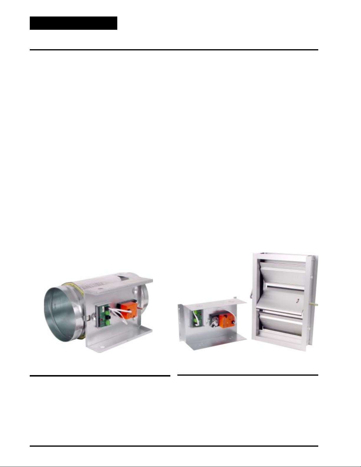
Figure 1-6: Round Bypass Damper
Figure 1-7: Rectangular Bypass Damper & Kit
16 Auto-Zone Systems
Page 17

Fan
RA Sensor
SA Sensor
Return Air Duct
Supply Air Duct
SP Pickup
Bypass Damper
SP Sensor
Fan
Zoning Design Guide
SA Sensor
Bypass Damper
SP Pickup
Supply Air Duct
RA Sensor
Return Air Duct
SP Sensor
3D
Min.2DMin.
Figure 1-8: Preferred Sensor Location
If the trunk ducts are properly sized for minimum pressure drop, the location of the static pickup probe is not
particularly critical. It should ideally be located at right
angles to the airflow in a straight section of the supply
duct approximately 2/3 the distance of the total length
of the supply duct. Also the probe should be located
not less than 3 duct diameters downstream and 2 duct
diameters upstream of any elbow or takeoff. See Fig-
ure 1-8.
Fan
RA Sensor
Return Air Duct
Supply Air Duct
Tubing To Be Equal
Length And Size
SP Pickups
Bypass Damper
SA Sensor
SP Sensor
Figure 1-10: Least Desirable Sensor Location
If the supply duct comes directly from the unit and im-
mediately splits in opposite directions, the pressure
pickup should be located ahead of the split, or as close
to it as possible, even if the bypass damper(s) are located downstream of the split.
Step #6 - Sizing the Zone Damper
Use a load program to determine the peak load for each
zone. These calculations will be used in selecting the
appropriate zone damper sizes.
Using the maximum acceptable velocity for a branch
duct (typically 1000-1500 FPM for minimal noise), find
the smallest damper that will deliver the required CFM
as determined by the load program.
Locate the branch velocity used in the duct design program on the left hand column of the damper sizing chart
(T able 1-1). Move across the chart and find the damper
which will provide the acceptable CFM to meet your
specific zone requirements.
Note Compare the damper size selected against
Figure 1-9: Acceptable Sensor Location
Since the “ideal” location is often difficult to find in an
installation, a location in the main trunk where the tip
is not in a “negative pressure area” (e.g. just downstream
of the inside curve of an elbow) or an area where the
tube opening is directly impacted by the velocity of the
supply air. See Figure 1-9.
One additional damper may be slaved together for large
zones. See zone wiring diagram for details. This should
be reserved for situations when it is not practical to use
a single large damper . Round zone dampers can be specified to be either pressure dependent or independent.
the duct size to determine if the next size
up or down will provide acceptable
performance without requiring a transition fitting.
Auto-Zone Systems 17
Page 18

Zoning Design Guide
Zoning Design Procedures
Pressure Dependent Dampers
With pressure dependent (PD) dampers, the minimum
and maximum airflow is set based on damper position.
During the final commissioning of the system, each zone
is typically balanced with a flow hood and the min/max
position is fixed either mechanically or the preferred
method, in the controller software. Since this min/max
setting is based only on position, as the static pressure
fluctuates it will cause the actual airflow at the zone
damper to increase or decrease. Therefore the name,
pressure dependent since the airflow is dependent on
the static pressure. Pressure dependent dampers are
available in round or rectangular configurations. See
Figure 1-1 1 for a diagram of a typical pressure dependent zone damper.
dent operation. Pressure independent operation is available for round zone dampers only. Pressure independent rectangular dampers are not available. See Figure
1-12 for a diagram of a typical pressure independent
zone damper.
When pressure independent dampers are used they must
be field calibrated so the CFM of airflow for the minimum and maximum airflow setpoints will be correct.
This should be done by the field technician during the
commissioning portion of the system installation. The
K-factor is the amount of airflow in CFM that the specific damper will produce with 1” W .C. duct static pressure on the damper flow sensor. This K-factor is used
by the controller software to maintain the correct minimum or maximum airflow setpoint regardless of the
static pressure at the flow sensor. The K-factor and the
minimum and maximum damper CFMs can be entered
at the Zone Manager on Basic systems, or using the
System Manager on Auto-Zone Plus systems. K-factors can also be entered using a personal computer with
the ZoneView computer front end software installed.
The K-factors for each damper size are listed in Table
1-1: Round Air Damper Selection. Once the correct Kfactors and minimum and maximum damper CFM
setpoints are entered, the damper will modulate to try
to maintain these CFM airflows during damper operation. If zone dampers or fan terminal units manufactured by others are used, the correct K-factors must be
obtained from the equipment manufacturer.
Figure 1-11: Pressure Dependent Damper
Pressure Independent Dampers
When using pressure independent (PI) dampers this
minimum and maximum is set based on actual CFM of
airflow through the damper. Airflow is measured using
a pickup tube mounted in the zone damper and an electronic air flow sensor. Using this method you always
know the actual airflow through each zone damper instead of just the damper percentage open. The minimum and maximum settings are based on this actual
airflow reading. As the static pressure fluctuates, the
flow sensor reads the variation and automatically repositions the damper to maintain the minimum or maximum flow setpoints. Since the minimum or maximum
airflow is maintained independently of the static pressure available in the duct it is called pressure indepen-
Figure 1-12: Pressure Independent Damper
18 Auto-Zone Systems
Page 19

Zoning Design Guide
Round Damper
Blade Assembly
1/2" Foil Faced
Insulation
AIRF
FLOW
LO
IR
A
W
Bypass & Slave Dampers Zone Dampers
Damper Round Duct Size
CFM @ 1” Velocity Pressure
Air Flow Probe “K” Factor- For Pressure
Independent Applications Only
(Area Ft
2
)
Round Damper
Blade Assembly
Zone Controller
1/2" Foil Faced
Insulation
Actuator
Control Enclosure
(Cover Removed)
Bypass & Slave Interface
Table 1-1: Round Damper Selection Data
6”
(0.188)
474 950 1417 2120 2908 3700
8”
(0.338)
10”
(0.532)
L
F
IR
A
W
12”
(0.769)
W
A
O
I
R
F
L
O
Actuator
Control Enclosure
(Cover Removed)
14”
(1.050)
16”
(1.375)
Velocity Through Zone Damper
FPM
750 - Zone
141
(0.03)
1000 - Zone
188
(0.05)
1250 - Zone
235
(0.07)
1500 - Zone
282
(0.09)
1750 – Bypass Only
329
(0.12)
2000 – Bypass Only
376
(0.15)
2250 – Bypass Only
423
(0.18)
WattMaster reserves the right to change specifications without notice
Rectangular Dampers
Auto-Zone rectangular dampers are high quality aluminum construction with opposed/air foil designed
blades for superior control and have both blade and jamb
seals for tight shut off. The dampers are installed using
a mounting flange. The purpose for the flange mounting is to allow as much unrestricted free space within
the duct as possible.
Many companies utilize slide-in type dampers which
Airflow Through Zone Damper - CFM
inches W.C . With Air Damper Full Open)
(∆P
S
254
(0.02)
338
(0.03)
423
(0.04)
507
(0.06)
592
(0.08)
676
(0.10)
761
(0.13)
399
(0.01)
532
(0.02)
665
(0.03)
798
(0.04)
931
(0.06)
1064
(0.07)
1197
(0.09)
577
(0.02)
769
(0.03)
961
(0.04)
1154
(0.05)
1346
(0.06)
1538
(0.07)
1730
(0.09)
788
(0.01)
1050
(0.02)
1313
(0.03)
1575
0.04)
1838
(0.05)
2100
(0.07)
2363
(0.08)
1031
(0.01)
1375
(0.01)
1718
(0.02)
2062
(0.03)
2405
(0.04)
2749
(0.05)
3094
(0.06)
can cause air flow problems. These slide-in dampers
require that the damper frame be inside the duct. Imagine an 8 x 10 rectangular duct using a slide in damper
with a frame thickness of 1”. The frame alone would
reduce the opening to 6 x 8.
Another possible problem encountered with rectangular dampers is the blade width. Many damper manufacturers supply dampers with 6” or 8” dampers blades.
This can become a major problem, for example, if the
Auto-Zone Systems 19
Page 20

Zoning Design Guide
Zoning Design Procedures
damper has a height of 10”. In this case the damper
would utilize an 8” blade and a 2” blade stop or dam
would be installed across the base of the damper. Taking into consideration the “blade stop” and the frame, a
10 x 10 damper would have a reduced opening of 6 x 8
inside the duct. Many contractors have experienced low
air flow problems on projects only to discover this hidden problem of the dampers actually creating the restriction. Auto-Zone utilizes a variety of blade widths
in order to accommodate the size of the damper instead
of the damper trying to accommodate the size of the
blade.
Table 1-2: Rectangular Damper Selection Data
Rectangular Dampers
Damper
Height
“B”
Damper
Width
“A”
8” 410
10” 510
12” 560
14” 660
16” 750
18” 770
20” 850
22” 930
24” 950
26” 990
28” 1070
30” 1020
32” 1090
34” 1150
36” 1060
8” 10” 12” 14” 16” 18” 20” 22” 24” 26” 28” 30” 32” 34” 36”
Airflow Data with Full Open Damper – CFM @ 1000 FPM Velocity
For airflow CFM at other velocities use these multipliers: 750 FPM = 0.75, 1250 FPM = 1.25, 1500 FPM = 1.5, 2000 = 2.0, 2250 = 2.25
530
640
740
850
(0.16)
(0.10)
(0.07)
(0.05)
(0.04)
590
690
800
910
(0.10)
(0.07)
(0.05)
(0.03)
(0.03)
650
730
850
970
(0.07)
(0.05)
(0.03)
(0.02)
(0.02)
770
880
1030
1180
(0.05)
(0.03)
(0.02)
(0.02)
(0.01)
890
1030
1200
1370
(0.04)
(0.03)
(0.02)
(0.01)
(0.01)
980
1180
1380
1580
(0.03)
(0.03)
(0.01)
(0.01)
(0.01)
1090
1330
1550
1770
(0.03)
(0.02)
(0.01)
(0.01)
(0.01)
1210
1480
1730
1980
(0.02)
(0.01)
(0.01)
(0.01)
(0.01)
1290
1630
1900
2170
(0.02)
(0.01)
(0.01)
(0.02)
(0.01)
(0.01)
(0.01)
(0.01)
(0.01)
1390
(0.01)
1500
(0.01)
1550
(0.01)
1660
(0.01)
1770
(0.01)
1790
(0.01)
(0.01)
1780
2080
(0.01)
(0.01)
1930
2250
(0.01)
2080
2430
(0.01)
2230
2600
(-)
2380
2780
(-)
2520
2670
(-)
WattMaster reserves the right to change specifications without notice
(-)
2380
(-)
2570
(-)
(-)
2780
(-)
(-)
2970
(-)
(-)
3180
(-)
(-)
3090
(-)
(-)
(∆PS - inches W.C. @ 1000 FPM Velocity)
970
(0.03)
1030
(0.02)
1090
(0.01)
1330
(0.01)
1540
(0.01)
1780
(0.01)
1990
(0.01)
2230
2440
2680
2890
3130
3340
3580
3510
1080
(0.03)
1150
(0.02)
1210
(0.01)
1480
(0.01)
1710
(0.01)
1980
(0.01)
2210
2480
(-)
2710
(-)
2980
(-)
3210
(-)
3480
(-)
3710
(-)
3980
(-)
3930
(-)
1190
(0.02)
1260
(0.01)
1330
(0.01)
1630
(0.01)
1880
(0.01)
2180
2430
(-)
2730
(-)
2980
(-)
3280
(-)
3530
(-)
3830
(-)
4080
(-)
4370
(-)
4350
(-)
1300
(0.02)
1380
(0.01)
1460
(0.01)
1760
(0.01)
2060
(-)
2350
(-)
(-)
(-)
(-)
(-)
(-)
(-)
(-)
(-)
(-)
(-)
2650
(-)
2950
(-)
3250
(-)
3550
(-)
3850
(-)
4150
(-)
4450
(-)
4750
(-)
5040
(-)
1410
(0.02)
1500
(0.01)
1580
(0.01)
1910
(0.01)
2230
2550
2870
3200
3520
3850
4170
4500
4820
1520
(0.01)
1610
(0.01)
1700
(0.01)
2060
2400
(-)
2750
(-)
3090
(-)
3450
(-)
3790
(-)
4150
(-)
4500
(-)
4850
(-)
(-)
NA NA NA NA NA NA
NA NA NA NA NA NA
1630
(0.02)
1730
(0.01)
1820
(0.01)
2210
(-)
2570
(-)
2950
(-)
3310
(-)
3700
(-)
4060
(-)
4450
(-)
4820
(-)
(-)
NA NA NA NA NA
1740
(0.01)
1840
(0.01)
1940
2360
(-)
2740
(-)
3150
(-)
3530
(-)
3950
(-)
4330
(-)
4750
(-)
(-)
NA NA NA NA
1850
(0.01)
2000
(0.01)
2060
(-)
(-)
(-)
(-)
(-)
(-)
(-)
(-)
NA NA NA
(-)
2510
(-)
2910
(-)
3350
(-)
3750
(-)
4200
(-)
4600
(-)
NA NA
1970
(0.01)
2080
(0.01)
2190
(-)
2640
(-)
3090
(-)
3540
(-)
3990
(-)
4440
(-)
4880
(-)
20 Auto-Zone Systems
Page 21

Zoning Design Guide
Auxiliary Heat Control Options
The Auto-Zone Zoning system offers the user a variety
of methods to deal with zone heating requirements. In
order to control zone heat, an optional Relay Expansion Board is required. When deciding how to handle
zone heating requirements the user should consider the
following:
• Does the rooftop unit have heat?
• Are you using fan-powered boxes with reheat?
• Is auxiliary heat such as baseboard or radiant
ceiling panels used?
If the zone has some type of heat, the user must consider how the heat is to be used. Typical questions that
should be asked:
Q: Should the zone heat be used as a first stage where
it will become active before a heating demand is
created at the rooftop unit?
A: This mode is useful if you expect to have both
heating and cooling demands at the same time. The
zone will use it’s own heat and allow the rooftop
unit to continue to provide cooling for other zones.
This mode is also useful if the roof top unit does
not have any heating capabilities.
Q: Is the zone heat only to be used as a second stage,
where it will be activated only if the roof top unit
cannot maintain the space temperature, such as
during very cold weather?
A: In this mode of operation the rooftop will examine
the heating and cooling demands and try to satisfy
all of the zones by switching between heating and
cooling as required. The zone heat will only be
activated if the zone temperature falls below a
selected limit.
Relay Expansion Board Outputs
The following describes the operation of each of the
relays on the optional relay expansion board. The user
can choose the appropriate relays for any given application.
Relay #1 - Parallel Fan
If the Zone is in cooling or vent mode, the parallel fan
can activate anytime the zone temperature drops 0.5° F
below the heating setpoint. It deactivates when the temperature rises above the heating setpoint.
Relay #2 - Box Heat
If the zone is in cooling or vent mode then the box heat
can activate anytime the zone temperature drops 1.5° F
below the heating setpoint. It deactivates when the temperature rises to within 1.0° F of the heating setpoint.
Box heat is not allowed to activate in the heating mode
when there is hot air being supplied by the air handling
unit. This output was intended to allow zone reheat
while the Zone Manager is satisfying cooling demands
in other zones.
Relay #3 - Aux. Heat
In the occupied mode, the aux heat can activate anytime the zone temperature is 0.5° F below the aux heat
setpoint. It deactivates when the temperature rises 0.5°
F above the aux heat setpoint. In the unoccupied mode,
the aux heat uses the unoccupied heating setpoint with
the same deadband values mentioned above. This prevents the zone from maintaining the same aux heat
setpoint at night that it does during the daytime. The
Parallel Fan and Box Heat are prevented from coming
on until the aux heat is energized.
This output was intended to allow zone heating to augment the normal heating mode and also to allow a zone
an attempt to satisfy its own heating needs before creating a heating demand at the Zone Manager.
Q: Should the zone heat be locked out if the rooftop
unit is supplying warm air?
A: Many times it is desirable to use the rooftop
heating whenever possible and only use zone heat
when the rooftop unit is in cooling. This mode of
operation will lockout zone heat if the rooftop is
delivering heated air.
Relay #4 - Series Fan
The series fan runs anytime the main fan is running.
This includes occupied and unoccupied modes. The fan
can only start running when the zone damper is closed,
so it determines that the damper is closed before starting the fan.
Auto-Zone Systems 21
Page 22

Zoning Design Guide
System Installation
Mounting Of Controllers
All Auto-Zone Round Dampers or Rectangular Damper
Kits have the required controllers, actuators etc. factory mounted in an indoor rated control enclosure. If
you wish to use another manufacturers dampers for zoning control you must purchase Zone or Bypass Packages from WattMaster. These are furnished without a
mounting enclosure. Most local codes require these
components be mounted in an enclosure. If yours does
not require this it is still strongly recommended that
you do mount them in an enclosure. Components that
are not in an enclosure are in danger of being damaged,
and are susceptible to dirt and moisture contamination.
You may furnish your own enclosure or one is available from WattMaster. The part number for the
WattMaster enclosure is EE000075-01. This is an indoor rated enclosure. If the zone mounting location is
susceptible to water damage, watertight enclosures can
be purchased at any local electrical supply. Mounting
location for the controllers should not violate any local, state or national codes.
device. Possible problems you may encounter using
common transformers to power multiple devices are:
• If polarity is not maintained between devices,
shorting of the transformer will occur resulting
in damage to the electronics.
• When using one transformer to power multiple
devices it is possible to lose most or all of your
system if the transformer fails.
• It is important when powering multiple devices
from one transformer that total VA load and
wiring voltage drops be taken into account for
proper sizing of the transformer and wire.
(See Table 3 on page 23)
It is therefore recommended that in most installations
individual transformers be installed for each device.
This will greatly reduce the possibility of errors and
possible damage to the system.
System Wiring
Wiring requirements for Auto-Zone systems can be broken down into four main categories:
1.) Power Wiring
2.) Communications Wiring
3.) Controller Wiring
4.) Sensor Wiring
Each category should be thoroughly understood and
implemented in order to have a trouble free installation.
Power Wiring
All Auto-Zone devices are powered by 24 VAC. It is
possible to power the system using one or more common transformers or individual transformers for each
Power wiring should always be done in accordance with
any local, state, or national codes.
It is also important to note that THE HVAC UNITS
FACTORY TRANSFORMER SHOULD NEVER
BE USED TO POWER Auto-Zone devices! Normally
transformers on typical HVAC units are sized to only
handle the load of the units factory installed controls.
A separate transformer must be used.
Communication Loops
The Auto-Zone system utilizes two different communications loops. The Basic system uses a 9600 Baud
RS-485 communications loop (Local Loop) only. The
Plus system uses two different communications loops.
It has a 9600 Baud RS-485 communications loop (Local Loop) like the Basic system but also has an RS-485
19200 baud communication loop (Network Loop) that
connects the Zone Managers together and connects the
CommLink II communications interface.
22 Auto-Zone Systems
Page 23

Zoning Design Guide
W attMaster requires that all communication wire be 18
gauge minimum, two wire shielded cable, Belden
#82760 or equivalent. W attMaster offers AZWR series
communications cable for this purpose. The 18 gauge
color coded and labeled wire is available for the local
loop and the network loop communications wiring. The
local loop wire is supplied in 1000 ft. spools and is labeled “Local Loop” with a green candy stripe. The
network loop wire is supplied in 500 ft. spools and is
labeled “Network Loop” with a red candy stripe.
Local Loop Wire
Figure 1-13: WattMaster Communications Wire
The loop is best connected in a daisy chain configuration, meaning the loop is connected from one controller to another. It is not necessary to sequentially address the zone controllers in relation to their location
on the loop.
Even though the daisy chain configuration is preferred,
the star configuration can also be used. If required, a
combination of the two can also be used. Remember,
the best communications loop wiring is the one which
utilizes the minimum number of ends while using the
shortest wiring path.
Communication Wiring terminals on most Auto-Zone
controllers are marked “T”, “R” and “SHLD” (Note:
instead of SHLD the CommLink is marked “G” and
the Basic Zone Manager is marked “SH”). All wiring
should be connected T to T , R to R and SHLD to SHLD
throughout the entire loop system. Communication wire
Network Loop Wire
should be color coded to facilitate error free wiring.
The communication loops will not work if any of the
wires are reversed or otherwise landed incorrectly . Communications loops can be run up to a maximum of approximately 4000 ft. in total length. If your system exceeds this length, please consult the WattMaster factory for more information regarding extended communication loop lengths and solutions.
Caution: Unless the communications loop
is installed in conduit, be careful to
position the cable away from high
noise devices like fluorescent
lights, transformers, VFD’s, etc.
Conduit is not required for communications loop wiring unless
required by local codes.
Tip: Incorrect wiring of the communications
loop is the most common mistake made
during installation. Before beginning
installation, write down the wire color
used on each terminal connection and
consistently maintain that color code. It
is recommended that a continuous wire
run be made between devices. Anytime
a splice is made in the cable you increase
your chance of problems. If a splice must
be made,
should be soldered and wrapped or if
soldering is not possible use butt splice
crimp connectors and wrap tightly with
electrical tape.
Caution: Make sure when you are inserting
Never use wire nuts! Cable
wires into the terminal blocks that
strands of wire do not stick out and
touch the adjacent terminals. If
adjacent wires touch each other or
another terminal, shorting and
subsequent damage to the circuit
board could result
Auto-Zone Systems 23
Page 24

Zoning Design Guide
COMM
LINK
II
COMM
LINK
II
System Installation
Computer
(Optional)
C
O
M
M
LINK
II
L
O
C
O
O
M
P
M
O
D
P
E
M
WCLI
AT
T
M
A
S
T
E
R
O
N
T
R
O
S,N
C
CommLink II
(Optional)
S
y
c
h
r
o
n
o
u
s
D
a
t
a
L
i
n
k
SIG
DET
RDY
SND
REC
PWR
CO
NTROLS
Remote Link
(Optional)
RS485 Loop
24VAC
RS485 Loop
HVAC Unit
Zone Manager
UTO-ZONE
A
AUTOZONE
WEDJANUARY11 2001
OCCUPIED
Zone Controllers Occupy
Addresses 1 through 16.
Zone
Controller #1
RAM
R
R
8K
32K
34
18
FLOW
CX4
CX3
CX8
U4
U3
U
8
RN1
1
M
V
B31920P
74H
S6264L-70P
4.00F
AZ
9936
C
ZO
573N
S
D5
N
C
E
094
C
R
27
CX9
U9
C
C
LM
13
9
C
66
RAM
EPROM
C8
2
C
14
80C55
R22
2
D5
A
V
D
R
P.U.
J
EF
C
R32
10
X
R23
1
P
6W
T'STA
ILIPS
R
-5-1
R24
2
U11
T
M
8
/3
H
52
5
0S
R
=1
P
C
1
0C
94
R
1
50
9
8
9
2
1
S
0
IP
06
IL
FD
CB
C
H
P
P
50
D
15
C
E
X
W
R25
U
5
D
D7
5
O
ADDRE
G
SS
ADD
CX10
9
1
U
3C
6
2
R
4
C
75176
8
6
4
O
S
M
C
U
C
8
W
X
M
10
3
1
6
16
32
LD3
P
C
TOKEN
C
O
5
4
W
R
NET
10
E
R
R26
R
1
R14
0
3
V
1
250
D4
LD
LD
R
F1
2
1
21
R
C
9
6
562
Y
S
R
101
E
REC
SCAN
R
R
R
V
fTimesNew
.2
12
1
10
1
L1
fTimesNew
Roman|b0|i0|
Roman|b0|i0|c0|p18;
c0|p18;OMRON
G5L-114P-PS
24VDC
CONTACT:
MDL
Q
VR1
UL/CSA5A250VAC
D
K
2
1
1
D3
T
C7
fTimesNew
7824
7824C
R
24VAC
fTimesNew
15
Roman|b0|i0|
9936
Roman|b0|i0|c0|p18;
M
64A
c0|p18;OMRON
G5L-114P-PS
MC340
24VDC
CONTACT:
Q
U
R16
D
UL/CSA5A250VAC
3
7
R17
2
K2
GND
R5
R6
R7
P
J1
P
J2
V2
CX1
U
1
TC
U
32K
2V
16L8
R1
R2
R3
CX2
Q
1
B
7
4H
3
19
U
C
C
2
1
20
2
59
PS
C
2
R4
S
IO
N
TO
R
E
XP
A
N
AC
T
U
A
Controller #16
D5
5
62
R
E
V
.
2
24VAC 24VAC
Zone
RAM
R
R
8K
32K
3
1
FLOW
4
8
CX4
CX3
CX1
CX8
U4
U3
U
8
U
RN1
1
TC
1
M
V
B
74
U
S
4.00F
31
AZ
32K
62
H
9
93
92
C
64
ZO
57
6
0P
L-7
2V
3N
S
N
C
0P
E
094
C
R
27
16L8
CX9
U9
R1
C
C
LM
1
9
R2
3
C
66
RAM
EPROM
C
R3
2
8
C
1
80C55
R22
4
CX2
2
D5
AD
VR
Q
P.U.
1
J
E
C1
F
R32
X
0
R23
B
7
1
P
4H
3
19
6W
U
C
C
2
1
20
T'STA
2
ILIPS
R
-5-1
59
R24
2
U
T
PS
M
8
/3
H
52
1
C
5
0S
1
R
=1
2
P
C
1
0C
94
R
1
50
9
8
9
2
1
S
0
IP
06
IL
FD
CB
C
H
P
P
50
D
1
R4
5
C
E
X
W
R25
R5
U
5
D
D7
5
O
ADDRE
R6
G
SS
ADD
R7
CX10
P
9
1
U
3C
J1
S
E
6
2
R
IO
XP
4
C
7
8
6
N
4
51
O
A
SW
N
M
C
U
C
76
8
X
M
10
3
1
6
16
32
LD3
P
C
TOKEN
C
O
5
4
W
R
P
NET
10
E
J2
R
R26
R
TO
AC
1
R
0
3
1
V
R
T
4
1
250
U
D4
A
LD
LD
R
F1
2
1
2
1
R
C
9
6
Y
S
10
REC
SCAN
R
R
R
fTimesNew
1
12
1
10
1
L
fTimesNew
Roman|b0|i0|
1
Roman|b0|i0|c0|p18;
c0|p18;OMRON
G5L-114P-PS
24VDC
CONTACT:
MDL
Q
VR1
UL/CSA5A250VAC
D
K
2
1
1
D3
T
C7
fTimesNew
7824
7824C
R
24VAC
fTimesNew
15
Roman|b0|i0|
9936
Roman|b0|i0|c0|p18;
M
64A
c0|p18;OMRON
G5L-114P-PS
MC340
24VDC
CONTACT:
Q
U
R16
D
UL/CSA5A250VAC
3
7
R17
2
K2
GND
V2
Figure 1-14: Auto-Zone Basic System Communication Loop Wiring
Zone Controllers Occupy
Addresses 1 through 16.
CV Controllers And Other
Add On Devices, Occupy
Addresses 18 trough 30
Computer
(Optional)
RS485
Network Loop
24VAC
HVAC Unit #1
Zone Manager
19200 Baud
9600 Baud
C
O
M
M
L
I
N
K
I
I
L
O
C
O
O
M
P
M
O
D
P
E
M
WCLI
AT
T
M
A
S
T
E
R
O
N
T
R
O
S,N
C
CommLink II
SychronousDataLink
SIG
DET
RDY
SND
REC
PWR
CON
T
ROLS
Remote Link
(Optional)
Network Loop
To Other Zone
Managers
24VAC
RS485 Local
Loop #2
RS485 Local
Loop #1
HVAC Unit #2
Zone Manager
The Loop Does Not
Have To Follow The Board
Address Sequence
Zone
Controller #1
RAM
R34
R18
8K
32K
FLOW
CX4
CX3
CX8
U4
U3
U
8
RN1
1
M
V
B
74H
S
4.00F
31920PS
A
6264L-70P
9936
ZZ
C
573N
O
D5
N
C
E
094
C
R
2
7
CX9
U9
C
C
LM
13
9
C
6
RAM
62
EPROM
C
8
C
14
80C55
R22
2
D5
A
V
D
R
P.U.
J
EF
C
R32
10
X1
S
R23
P
6W
-1
T'STA
ILIP
R
R24
28
U
T
2-5
M
S
1
1/3
55
1
R
C
40
PH
C
0=
19
R
1
80
99
20
65
1
S
B
D
IP
IL
F
C
C
00
H
P
P
5
D
15
C
E
X
W
R25
U
5
D
D7
5
O
ADDRE
G
SS
ADD
CX10
P
93C
1
U
J1
6
2
R
46
C
75176
8
4
O
S
M
C
U
C
8
W
X6
M
10
3
1
16
32
LD3
P
C
TOKEN
C
O
5
4
W
R
P
NET
100
E
J2
R
R26
R
13
R
14
V
1
250
D4
L
L
D
D
R
F1
2
1
21
R
C
9
6
562
YS
R
101
EV
REC
SCAN
R
R
R
fTimesNew
.2
12
1
10
1
L1
fTimesNew
Roman|b0|i0|
Roman|b0|i0|c0|p18;
c0|p18;OMRON
G5L-114P-PS
24VDC
CONTACT:
MDL
Q
VR1
UL/CSA5A250VAC
D
K
2
1
1
D3
T
C7
fTimesNew
7824
7824C
R
24VAC
fTimesNew
15
Roman|b0|i0|
9936
Roman|b0|i0|c0|p18;
M
64A
c0|p18;OMRON
G5L-114P-PS
MC340
24VDC
CONTACT:
Q
U
R16
D
UL/CSA5A250VAC
3
7
R17
2
K
2
GND
V2
24VAC
Zone
Controller #1
RAM
R
R
8K
32K
34
18
FLOW
CX4
CX3
CX8
U4
U3
U
8
RN1
1
M
V
B31920P
74HC
S
4.00F
AZZ
6264L-70PC
9936
573N
O
S
D5
N
C
E
094
R
27
CX9
U9
C
C
LM
13
9
C
66
RAM
EPROM
C
2
8
C14
80C55
R22
2
D5
AD
VR
P.U.
J
E
C
F
R32
10
X
R23
1
P
6W
T'STA
ILIPS
R
-5-1
R24
2
U
T
M
8
/3
H
52
1
5
0S
1
R
=1
P
C11
19
0C
94
R
50
9
2
S
B8
0
IP
06
IL
FD
C
C
H
P
P
50
D
15
C
E
X5
W
R25
U
D
D7
5
O
ADDRE
G
SS
ADD
CX10
P
93C
1
U
J1
6
2
R8
46
C
75176
4
O
S
M
C
U
C
8
W
X
M
10
3
1
6
16
32
LD3
P
C
TOKEN
C
O
5
4
W
R
PJ2
NET
100
ER
R
R26
13
R
14
V1
250
D4
LD
LD
R
F1
2
1
21
R
C
9
6
562
Y
S101
R
E
REC
SCAN
R12
R11
R10
V
fTimesNew
.2
L1
fTimesNew
Roman|b0|i0|
Roman|b0|i0|c0|p18;
c0|p18;OMRON
G5L-114P-PS
24VDC
CONTACT:
MDL
Q
VR1
UL/CSA5A250VAC
D
K1
2
1
D3
T
C7
fTimesNew
7824
7824C
R
24VAC
fTimesNew
15
Roman|b0|i0|
9936
Roman|b0|i0|c0|p18;
M
64A
c0|p18;OMRON
G5L-114P-PS
MC340
24VDC
CONTACT:
Q
U7
D
R16
UL/CSA5A250VAC
3
R17
2
K
2
GND
V2
24VAC
Zone
Controller #16
RAM
R
R
8K
32K
3
1
FLOW
8
4
CX4
CX1
U
1
TC
U
32K
2V
16L8
R1
R2
R3
CX2
Q
1
B31920P
74H
U
C
C
2
1
259
S
C
2
R4
R5
R6
R7
SIO
EX
P
N
A
N
TOR
AC
TU
A
CX3
CX1
CX8
U4
U3
U
8
U
RN1
1
TC
1
M
V
B
7
U
S
4H
4.00F
31
A
32K
62
9
ZZ
93
92
C
64
57
6
0P
L-7
2V
O
3N
S
D5
N
C
0P
E
094
C
R
2
7
16L8
CX9
U9
R1
C
C
LM
1
9
R2
3
C
6
RAM
62
EPROM
C
R3
8
C1
80C55
R22
4
CX2
2
D5
AD
VR
Q
P.U.
1
J
E
C
F
R32
10
X
S
R23
B
7
1
P
4H
3
19
6W
U
C
C
2
1
-1
20
T'STA
2
ILIP
R
59
R24
28
U
T
2-5
P
M
S
11
S
C
1/3
55
R
2
C
40
PH
C
0=
19
R
1
80
99
20
65
1
S
B
D
IP
IL
F
C
C
00
H
P
P
5
D
15
R4
C
E
X
W
R25
R5
U
5
D
D7
5
O
ADDRE
R6
G
SS
ADD
R7
CX10
P
9
1
U
3C
J1
S
6
2
R
IO
4
C
7
8
6
N
4
51
O
S
M
C
U
C
76
8
W
X
M
10
3
1
6
16
32
LD3
P
C
TOKEN
C
O
5
4
W
R
P
NET
1
E
J
R
R26
00
2
R
TO
1
R
3
1
V
R
4
1
250
D4
L
L
D
D
R
F1
2
1
21
R
C
9
6
5
Y
62
S
R
10
E
REC
SCAN
R
R
R
V
fTimesNew
1
.2
12
1
10
1
L
fTimesNew
Roman|b0|i0|
1
Roman|b0|i0|c0|p18;
c0|p18;OMRON
G5L-114P-PS
24VDC
CONTACT:
MDL
Q
VR1
UL/CSA5A250VAC
D
K
2
1
1
D3
T
C7
fTimesNew
7824
7824C
R
24VAC
fTimesNew
15
Roman|b0|i0|
9936
Roman|b0|i0|c0|p18;
M
64A
c0|p18;OMRON
G5L-114P-PS
MC340
24VDC
CONTACT:
Q
U
R16
D
UL/CSA5A250VAC
3
7
R17
2
K
2
GND
V2
24VAC
Zone
Controller #16
RAM
R
R
8K
32K
3
1
FLOW
4
8
CX4
CX1
U
1
TC
U
32K
2V
16L8
R1
R2
R3
CX2
Q
1
B
74H
31920P
U2
C1
C
259
S
C
2
R4
R5
R6
R7
S
E
IO
XPAN
N
TOR
A
C
TU
A
CX3
CX1
CX8
U4
U3
U
8
U
RN1
1
TC
1
M
V
B
74
U
S
4.00F
31
AZZ
32K
62
H
99
92
C
64
36
57
0P
L-70
2V
O
3N
S
D5
N
C
P
E
094
C
R
27
16L8
CX9
U9
R1
C
C
LM
9
1
R2
3
C
66
RAM
EPROM
C
R3
2
8
C
1
80C55
R22
4
CX2
2
D5
A
V
Q
D
R
P.U.
1
J
E
C
F
R32
1
X
0
R23
B
7
1
P
4H
31
6W
U
C
9
C
2
1
20
T'STA
2
ILIPS
R
-5-1
59
R24
2
U
T
PS
M
8
/3
H
52
1
C
5
0S
1
R
=1
2
P
C
19
0C
94
R
1
50
9
2
1
S
B8
0
IP
06
IL
FD
C
C
H
P
P
50
D
1
R4
5
C
E
X
W
R25
R5
U5
5
D
D7
O
ADDRE
R6
G
SS
ADD
R7
CX10
P
9
1
U
3C
J1
SIO
6
2
R
4
C
7
8
6
N
4
51
O
SW
M
C
U
C
76
8
X
M
1
3
1
6
0
16
32
LD3
P
C
TOKEN
C
O
5
4
W
R
P
NET
10
ER
J2
R
R26
TO
1
R
0
3
1
V
R
4
1
250
D4
LD
LD
R
F1
2
1
2
1
R
C
9
6
5
Y
62
S
R
10
E
REC
SCAN
R
R
R
V
fTimesNew
1
.
12
1
10
2
1
L
fTimesNew
Roman|b0|i0|
1
Roman|b0|i0|c0|p18;
c0|p18;OMRON
G5L-114P-PS
24VDC
CONTACT:
MDL
Q
VR1
UL/CSA5A250VAC
D
K
2
1
1
D3
T
C7
fTimesNew
7824
7824C
R
24VAC
fTimesNew
15
Roman|b0|i0|
9936
Roman|b0|i0|c0|p18;
M
64A
c0|p18;OMRON
G5L-114P-PS
MC340
24VDC
CONTACT:
Q
U
D
R16
UL/CSA5A250VAC
3
7
R17
2
K
2
GND
V2
24VAC
Constant Volume
(Addresses Start At 18)
COMM
T
SHLD
R
LD4
REC.
E
XP
A
N
A
C
TU
A
12V
AIN
1
AIN
2
AIN
3
AIN
4
AIN
5
GND
GND
AOUT
PRESSURE
SENSOR
To Any Other
CV Controllers
Or Add On Devices
Constant Volume
(Addresses Start At 18)
COMM
T
SHLD
R
LD4
REC.
EX
P
A
N
AC
T
U
A
12V
AIN
1
AIN
2
AIN
3
AIN
4
AIN
5
GND
GND
AOUT
PRESSURE
SENSOR
To Any Other
CV Controllers
Or Add On Devices
Controller
RAM
EPROM
485
COMM
ADDRESS ADD
G
DO
EW
0-5
VDC
YS101564
0-1
VDC
Controller
RAM
EPROM
485
COMM
ADDRESS ADD
DOG
EW
0-5
VDC
YS101564
0-1
VDC
32K
8K
COMM
TEST
24VAC
32K
8K
COMM
TEST
24VAC
RELAY
OUTPUT
COM
1-3
OUT
1
OUT
2
OUT
3
OUT
OUT
4
OUT
5
COM
4-5
4-5
PWR
GND
24VAC
RELAY
OUTPUT
COM
1-3
OUT
1
OUT
2
OUT
3
OUT
OUT
4
OUT
5
COM
4-5
4-5
PWR
GND
24VAC
Figure 1-15: Auto-Zone Plus System Communication Loop Wiring
24 Auto-Zone Systems
Page 25

Zoning Design Guide
Controller Wiring
All controller wiring should be in accordance with all
local, state, and national codes. It is recommended that
all wire be a minimum of 18 AWG unless otherwise
specified in the charts below. Controller connections
and wire sizing is as follows:
Zone Manager
• 24 VAC Supply Voltage (25 VA)
(2) Conductors - Determine minimum
wire size from Figure 1-16 on page 26.
• Communications Loop
(2) Conductors 18 gauge minimum
twisted pair with shield
(WattMaster communication wire,
Belden #82760 or equal)
• Supply Air Temperature Sensor
(2) Conductors 24 gauge minimum
• Return Air Temperature Sensor
(2) Conductors 24 gauge minimum
• Outside Air Sensor
(2) Conductors 24 gauge minimum
• Supply Static Pressure Sensor
(2) Conductors 24 gauge minimum
• Bypass Damper
(4) Conductors 24 gauge minimum
• HVAC Unit Control Wiring
(6) Conductors 24 gauge minimum
R (Common), G (Fan), Y1 (Cool 1),
Y2 (Cool 2), W1 (Heat 1), W2 (Heat 2)
For Auto-Zone Plus System With
Optional Staging Expansion Board up to
an additional (8) conductors Y3 through
Y6, W3 Through W6
System Manager
• 24 VAC Supply Voltage (25 VA)
(2) Conductors - Determine minimum
wire size from Figure 1-16 on page 26.
• Communications Loop
(2) Conductors 18 gauge minimum
twisted pair with shield
(WattMaster communication wire,
Belden #82760 or equal)
Zone Controller
• 24 VAC Supply Voltage (10 VA)
(2) Conductors - Determine minimum
wire size from Figure 1-16 on page 26.
• Communications Loop
(2) Conductors 18 gauge minimum
twisted pair with shield
(WattMaster communication wire,
Belden #82760 or equal)
• Room Sensor
(2) Conductors 24 gauge minimum
(3) Conductors if using optional slide
Sensor Wiring
Auto-Zone temperature sensors utilize a type III thermistor element that is one of the most commonly used
sensors in the building controls industry. Sensor wire
should be a minimum of 24 gauge however larger wire
such as 18 gauge is commonly used.
Conventional thermostat cable is acceptable in most
commercial and institutional installations. In some installations which have the potential for high electrical
noise, such as broadcast facilities (radio, TV , etc.), heavy
industrial (machinery, welding equipment, etc.), and
medical (x-ray, scanning, etc.), it is advisable to use
shielded cable on sensors which are located in or close
to these environments. The same cable used for the communication bus can be used in these situations.
Sensor requirements are:
• Supply Air Sensor
(2) Conductors 24 gauge minimum
• Return Sensor
(2) Conductors 24 gauge minimum
• Outside Air Sensor
(2) Conductors 24 gauge minimum
• Room Sensor
(2) Conductors 24 gauge minimum
(3) Conductors if using optional slide
adjust
Auto-Zone Systems 25
Page 26

Zoning Design Guide
System Installation
Some installers like to use one large 24VAC transformer to power several controllers. This is allowable as long as polarity is maintained to each
controller on the transformer circuit.
recommends using a separate transformer for each controller in order to eliminate the potential for damaging controllers due to incorrect
polarity.
Using separate transformers also allows redundancy in case of a transformer failure. Instead of having 8 controllers inoperative because of a
malfunctioning transformer you have only 1 controller off line. If the installer does decide to use a large transformer to supply power to several
controllers, the following transformer and wire sizing information is presented to help the installer correctly supply 24VAC power to the controllers.
Following is a typical example to help the installer to correctly evaluate transformer and wiring designs.
Each Zone Controller with actuator requires 10 VA @ 24VAC power. In the examples below we have a total of 8 Zone Controllers.
8 Zone Controllers @ 10VA each................ 8 x 10VA = 80VA.
The above calculation determines that our transformer will need to be sized for a minimum of 80VA if we are to use one transformer to power all the
controllers.
Next we must determine the maximum length of run allowable for the wire gauge we wish to use in the installation. Each wire gauge below has a
voltage drop per foot value we use to calculate total voltage drop.
18ga wire.................................0.00054 = voltage drop per 1’ length of wire
16ga wire.................................0.00034 = voltage drop per 1’ length of wire
14ga wire.................................0.00021 = voltage drop per 1’ length of wire
For our example we will use 18 gauge wire. WattMaster recommends 18 gauge as a minimum wire size for all power wiring.
Next use the voltage drop per foot value for 18 gauge wire from the list above and multiply by the total VA load of the 8 controllers to be installed.
0.00054 (Voltage drop per foot for 18 gauge wire) x 80VA controller load = Volts/Ft.
WattMaster controllers will operate efficiently with a voltage drop no greater than 2 Volts. Divide the total allowable voltage drop of 2 Volts by the
number you arrived at above and you have the maximum number of feet you can run the 18 gauge wire with an 80VA transformer with no more than a
2 Volt drop at the farthest controller from the transformer..
Parallel circuiting of the wiring instead of wiring all 8 controllers in series allows for longer wire runs to be used with the same size wire (as shown in
our examples below).
transformer size, multiple transformers, circuiting, etc., when laying out an installation. No matter what layout scheme is decided upon, it is mandatory
that the farthest controller on the circuit is supplied with a minimum of 22 Volts.
It is often necessary for the installer to calculate and weigh the cost and installation advantages and disadvantages of wire size,
Warning:
If polarity is not maintained, severe damage to the controllers may result. WattMaster Controls
2 (Volts total allowable voltage drop)
0.0432 (Voltage drop per 1 ft. @ 80VA load)
=
0.0432
46.30 feet
24VAC Power - Transformer & Wire Sizing Considerations
ZONE
CONTROLLER
B
A
ZONE
CONTROLLER
120 / 24VAC
ZONE
CONTROLLER
ZONE
CONTROLLER
Distance A to B cannot exceed 46.30 Ft.
ZONE
CONTROLLER
ZONE
CONTROLLER
ZONE
CONTROLLER
ZONE
CONTROLLER
ZONE
CONTROLLER
BC
ZONE
CONTROLLER
ZONE
CONTROLLER
ZONE
CONTROLLER
Distance from A to B cannot exceed 92.60 Ft.
Distance from A to C cannot exceed 92.60 Ft.
CONTROLLER
CONTROLLER
CONTROLLER
CONTROLLER
A
ZONE
ZONE
ZONE
ZONE
120 / 24VAC
Component Power Requirements
System Manager ........ ..............25VA GPC Controller.... .....................20VA
Zone Manager..........................25VA
Wetbulb Module .......................20VA
Zone Controller ........................10VA Lighting Panel Controller ..........25VA
CV Controller............................20VA
Zone Relay Expansion Board ...10VA
CV-C Controller................. .......20VA Staging Expansion Board .........20VA
Optimal Start Scheduler ...........25VA
Figure 1-16: Transformer And Wire Sizing Considerations
ZONE
CONTROLLER
ZONE
CONTROLLER
ZONE
CONTROLLER
BCDE
ZONE
CONTROLLER
ZONE
CONTROLLER
ZONE
CONTROLLER
A
120 / 24VAC
Distance from A to B cannot exceed 185.20 Ft.
Distance from A to C cannot exceed 185.20 Ft.
Distance from A to D cannot exceed 185.20 Ft.
Distance from A to E cannot exceed 185.20 Ft.
JOB NAME
FILENAME
WIRSIZ1.CDR
DATE:
11/30/99
PAGE
1
DESCRIPTION:
Wire & Transformer Sizing
CONTROLS
DRAWN BY:
Auto-Zone
B. CREWS
ZONE
CONTROLLER
ZONE
CONTROLLER
26 Auto-Zone Systems
Page 27

Application Notes:
Zoning Design Guide
Zoning 30 And 40 Ton Units
When using large HVAC units for zoning applications,
several rules must be considered to prohibit potential
problems.
Because of the large air flow capacities of the 30 and
40 ton units, great care must be taken in sizing zone
and bypass dampers.
Use these guidelines to help keep you out of trouble.
• Always use the Auto-Zone Plus system even
if you only have one unit that you are zoning.
• Generally you should use constant volume
units in your zoning system design. If your
units are to be equipped with variable
frequency drives or inlet vanes, please
consult WattMaster Controls for assistance.
• The OE340-10-AGSTG relay expansion card
is usually required for each Zone Manager
controlling two or more stages of cooling.
• Bypass dampers should be sized for 60 to
70% of the rated CFM of the unit. Because of
the large air volumes involved, rectangular
dampers should be used instead of round
dampers. Consult the rectangular damper
sizing guide (Table 1-2 on page 25), for CFM
ratings.
• Large units should always have a minimum
of 6 zones due to the high air flow capacities.
• To prevent excessive noise in the system,
zone damper total minimum airflow settings
should be equal to or preferably greater than
30% of the units rated CFM.
As an added precaution, we recommend a high duct
static safety switch be installed (Dwyer Model 19005-MR or equal) to prevent over pressurization of the
ductwork.
Auto-Zone Systems 27
Page 28

Form: WM-AZA-ZDG-01B Printed in the USA October 2001
All rights reserved Copyright 2001
WattMaster Controls Inc. • 8500 NW River Park Drive • Parkville MO • 64152
Phone (816) 505-1100 E-mail: mail@wattmaster.com Fax (816) 505-1101
 Loading...