

Page 1

ZoneView Plus
Computer Front End
Operations Manual
Page 2

Page 3

FACTORY CONTROLS SYSTEM
ZoneView Plus
Computer Front End Operations Manual
This document is subject to change without notice.
WattMaster Controls, Inc. does not assume responsibility
for errors, or omissions herein.
ZoneView Plus Computer Front End Operations Manual - Form WM-ZVP-CFE-01C
Copyright 2000 WattMaster Controls, Inc.
All rights reserved.
Page 4

Page 5

ZoneView Plus
Table of Contents
Overview.........................................................................................................1
System Requirements ....................................................................................1
Feature Summary ..........................................................................................2
Software Installation .....................................................................................3
ZoneView Plus Setup.....................................................................................5
Setup Serial Port ..............................................................................................................6
Alarm Polling Enabled.....................................................................................................7
AutoLog Interval..............................................................................................................7
Standard CommLink........................................................................................................8
Search For Units ............................................................................................9
Manually Adding Units..................................................................................................11
Print Unit Descriptions ..................................................................................................13
Exporting / Importing Unit Configurations .............................................14
Copy Phone List.............................................................................................................15
System User Setup .......................................................................................16
Description Programming ..........................................................................18
Comm Link II Setup....................................................................................19
Telephone Setup ...................................................................................22
Dialing Remote Job-Sites............................................................................24
Accessing Units ............................................................................................25
Sample Screens ............................................................................................27
Zone System Status Screen............................................................................................27
Toolbar Button Descriptions..........................................................................................28
Force Immediate Upload...........................................................................................29
Custom Screens.........................................................................................................29
Broadcast Time .........................................................................................................29
Week Schedules ........................................................................................................30
Holidays ....................................................................................................................32
View/Change Setpoints.............................................................................................33
Configuration Screen.................................................................................................36
Diagnostics Screen....................................................................................................37
Load Trend Log from Unit.............................................................................................38
Alarm Enable/Disable...............................................................................................40
Alarm Polling........................................................................................41
Terminal Mode ............................................................................................43
Load Tenant Logs........................................................................................44
Computer Front End
Page 6

ZoneView Plus
Start AutoLog.............................................................................................. 44
Download Code ........................................................................................... 45
About Window ............................................................................................ 45
Custom Screen Creation ............................................................................ 46
Select Unit......................................................................................................................49
Select Data .....................................................................................................................50
Select Font Color & Size ...............................................................................................51
Accessing a Custom Screen ...........................................................................................51
Accessing Status Screens from Custom Screens ...........................................................52
Compatible Controllers .............................................................................. 53
Computer Front End
Page 7

ZoneView Plus
Overview
Overview
OverviewOverview
ZoneView Plus provides the customer a complete Graphical Interface intended to ease
the user interaction with their building HVAC system. It provides a standard, easy to
understand Status Screen for each type of equipment installed. All controlling setpoints,
trend logs and alarm conditions are accessed in the ZoneView Plus environment.
ZoneView Plus can be configured for a direct On-Site installation or for a Remote
Modem connection to several installations.
NOTE: This manual assumes the user has a working knowledge of Windows 95/98
operation and does not describe, in detail, the process of copying files or other
windows related functions. Learning the operation of Windows is the
responsibility of the operator using this equipment.
System Requirements
System Requirements
System RequirementsSystem Requirements
To use ZoneView Plus you or your end user must have a computer that meets or exceeds
the following items:
• IBM™ compatible computer
• Pentium 200 MHz or Faster Microprocessor
• 64 Meg RAM
• Windows 95 / 98
• Super VGA Monitor w/ 1024 x 768 Resolution Minimum
• Available Serial Port for On-Site Installations or Modem for Remote Sites
• Microsoft Office 97 EXCEL™ to utilize Trend Log functions
Computer Front End 1
Page 8

Feature Summary
Feature Summary
Feature SummaryFeature Summary
ZoneView Plus provides a broad set of features:
• Ease of use
• Trend logs are created using EXCEL™ Spreadsheets
• Automatic installation
• Alarm Logs maintained on disk
• On-Site or Remote Modem installations
• User programmable descriptions for every piece of equipment
• User definable passcode levels for most setpoints
• Current status printouts
• User defined Custom Screens for floor plans, etc.
• Tenant Log retrieval of the Tenant Override Billing found VAV Box
Controllers
• Automatic retrieval of temperature trend logs, if configured properly
ZoneView Plus
2 Computer Front End
Page 9

ZoneView Plus
Software Installation
Software Installation
Software InstallationSoftware Installation
You must be running Windows with no other applications active. If other applications
are still running, you should terminate them before attempting to install ZoneView Plus.
You can check for applications running in the background by pressing the Ctrl-Alt-Del
keys all at the same time. If you see any virus protection programs or any other programs
that might interfere with the installation, you can terminate them using the End Task
button.
NOTE: If you are concerned about terminating a virus protection program, you can
scan the installation disk for viruses prior to actually installing the program.
Once the program is installed and the computer is rebooted, your virus
program will automatically restart if it was originally installed to run
whenever the computer is started.
In some cases the installation will determine that some existing files on your hard disk
need to be updated before the ZoneView Plus installation can continue. This is your
decision to make. In some cases you may lose operational capabilities with pre-existing
programs if you decide to update the requested files. York International assumes no
responsibility for any other program installed on your computer and cannot aid in
restoring operation to any affected programs. In most cases, but not all, the updating of
DLL files won’t cause harmful effects, but you have been forewarned!
If the ZoneView Plus installation does update a file with your permission, the computer
will need to be restarted and the Setup program run again to complete the installation
process. This does not occur automatically.
Installing from CD ROM
Select Run from the Start button menu. Enter the drive letter than contains the
ZoneView Plus cd rom disk followed by “setup” ( e.g. type “d:\setup” ), then press
<Enter> or select <OK> to begin the installation. The setup program will copy all files
from all the installations disks completely before the actual graphical installation screen
appears.
Computer Front End 3
Page 10

ZoneView Plus
Installation Continued…
The installation program asks you to provide a drive letter and a directory name on your
hard disk, to which the ZoneView Plus files will be copied. It will want to install the
program under the Program Files folder. This is not recommended as Windows 95/98
has problems with spaces contained in folder names and will not be able to perform
certain tasks requested by the ZoneView Plus program. You should install ZoneView
Plus in its own folder on the C:\ drive for best results. For example: C:\ZoneViewPlus
After all the files have been copied and uncompressed, the setup program will attempt to
“register” the copied library files with the Windows registry program. This may take a
few moments to complete.
If the installation is successful, a new program group with the ZoneView Plus ICON will
be created and the ZoneView Plus folder will be installed on the Programs Menu under
the Start button.
NOTE: This program was written for installation on a stand-alone computer. Network
installations or Windows NT installations have not been tested or certified.
You may attempt to install ZoneView Plus on either of these two setups, but
operation is not guaranteed and York International cannot aid in either of
these installation attempts.
4 Computer Front End
Page 11
ZoneView Plus
ZoneView Plus Setup
ZoneView Plus Setup
ZoneView Plus SetupZoneView Plus Setup
Before you can begin normal operations, a few things need to be configured to match
your particular installation. You will need to enter the default System Manager Level
passcode before proceeding. Select the Passcode Button (see below) and enter the default
passcode of “sm” to gain access to all configuration menus. The passcode is case
sensitive, so be sure to enter lower case text for this default value.
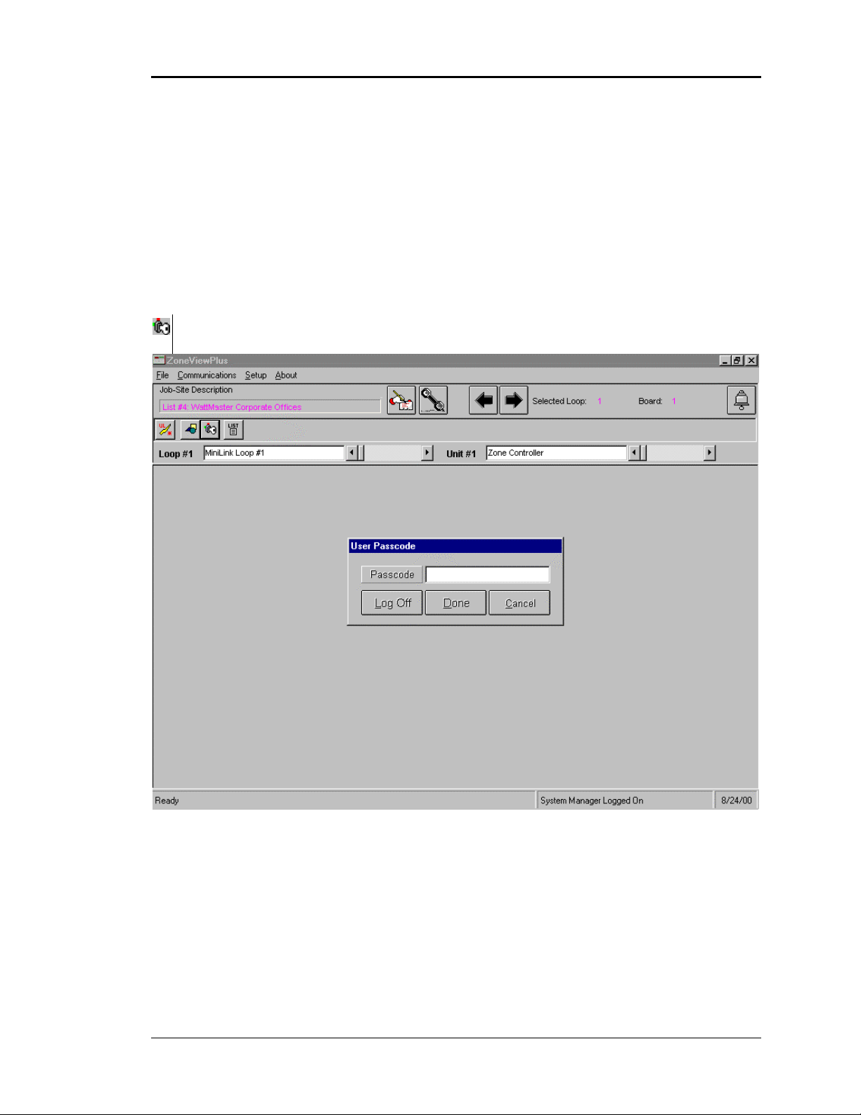
Select the Passcode ICON from the lower toolbar to access the User Passcode screen.
The passcode entry screen is shown above in the center of the ZoneView Plus main
screen. As you can see, you can secure the system by selecting the Log Off button, or you
can type in the passcode and press <Enter> to gain access to the system.
Use the Cancel key if you accessed this screen by mistake and don’t wish to change the
current access level. More detailed information on Passcode operation will be discussed
later in this manual.
Computer Front End 5
Page 12
ZoneView Plus
Setup Serial Port
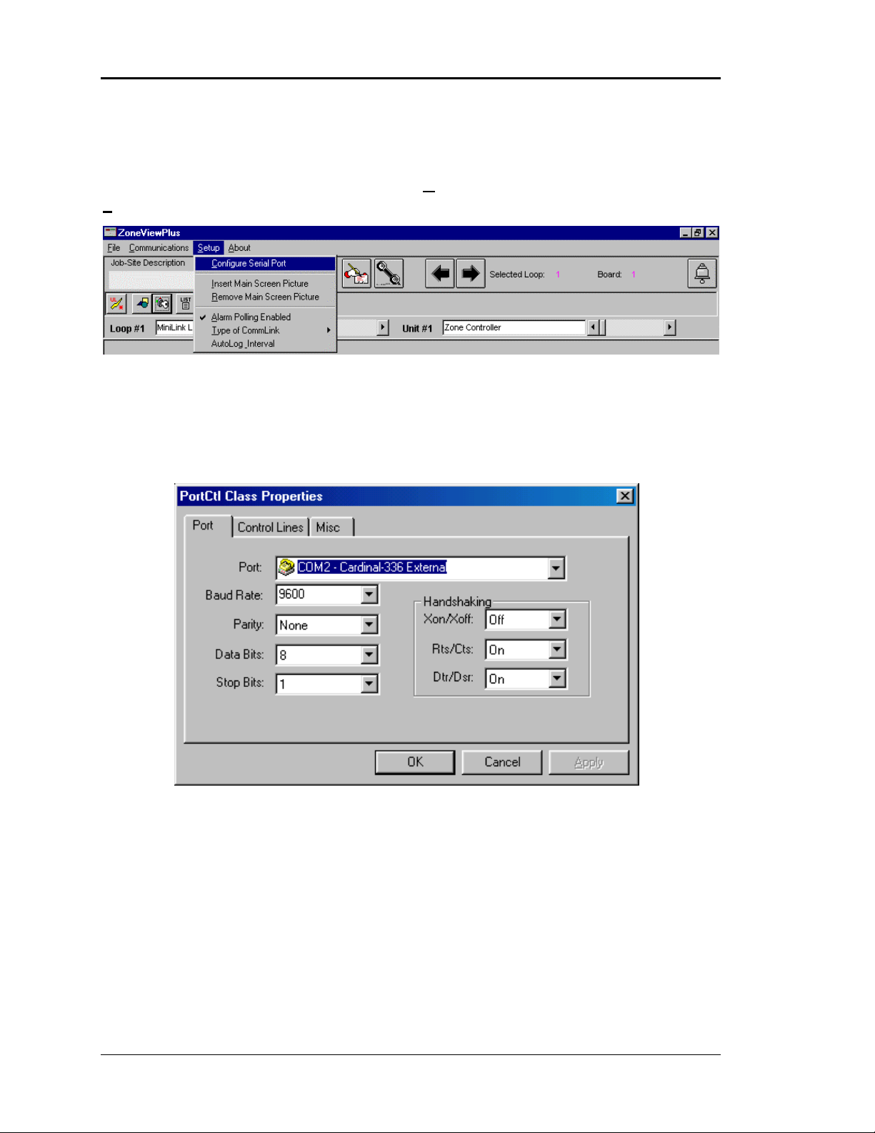
If ZoneView Plus displays “System Manager Logged On” on the lower Status Bar as the
current passcode level, you can now select the Configure Serial Port option from the
Setup menu.
The following window will appear onscreen. You need to make sure that you select the
port number that you have connected the CommLink II Interface into for direct onsite
installations. If you are using this as a remote access computer, then this port number
should match the location of your Internal or External Modem connection. We
recommend using Port #2 if at all possible to avoid IRQ conflicts and mouse conflicts.
Other than the Port selection shown on the sample screen, all other fields cannot be
changed. They are displayed to show what the exact configuration is. If you attempt to
alter any of the other fields, they will return to their default settings as soon as you exist
this screen. This prevents the user from accidentally creating a configuration that will not
operate correctly.
Your Port should show a list of all installed serial ports except the mouse port. As
mentioned above, select the port you will be using to communicate either directly or
through a modem. If you are using a modem and Windows 95/98 doesn’t recognize it,
then neither will ZoneView Plus!
6 Computer Front End
Page 13
ZoneView Plus
Alarm Polling Enabled
As you can see under the Setup menu, there is a menu item labeled Alarm Polling
Enabled. If this computer is being installed onsite, it can be configured to poll
automatically for alarm conditions on all units connected to the system. This requires that
the computer remains on continuous or the correct date and time of an alarm occurrence
will not be logged. The computers’ time and date are used to generate the time and date
of the alarms as they are detected.
If the menu displays the message Alarm Polling Disabled, simply click on this menu
item. A checkmark will appear and the text will change to Alarm Polling Enabled.
This feature should be disabled on remote setup computers until the job site is actually
called and connection made. At this point you can temporarily enable the alarm polling to
gather alarm information at the remote site. It is best not to leave this feature enabled all
the time when the computer is used for remote communications.
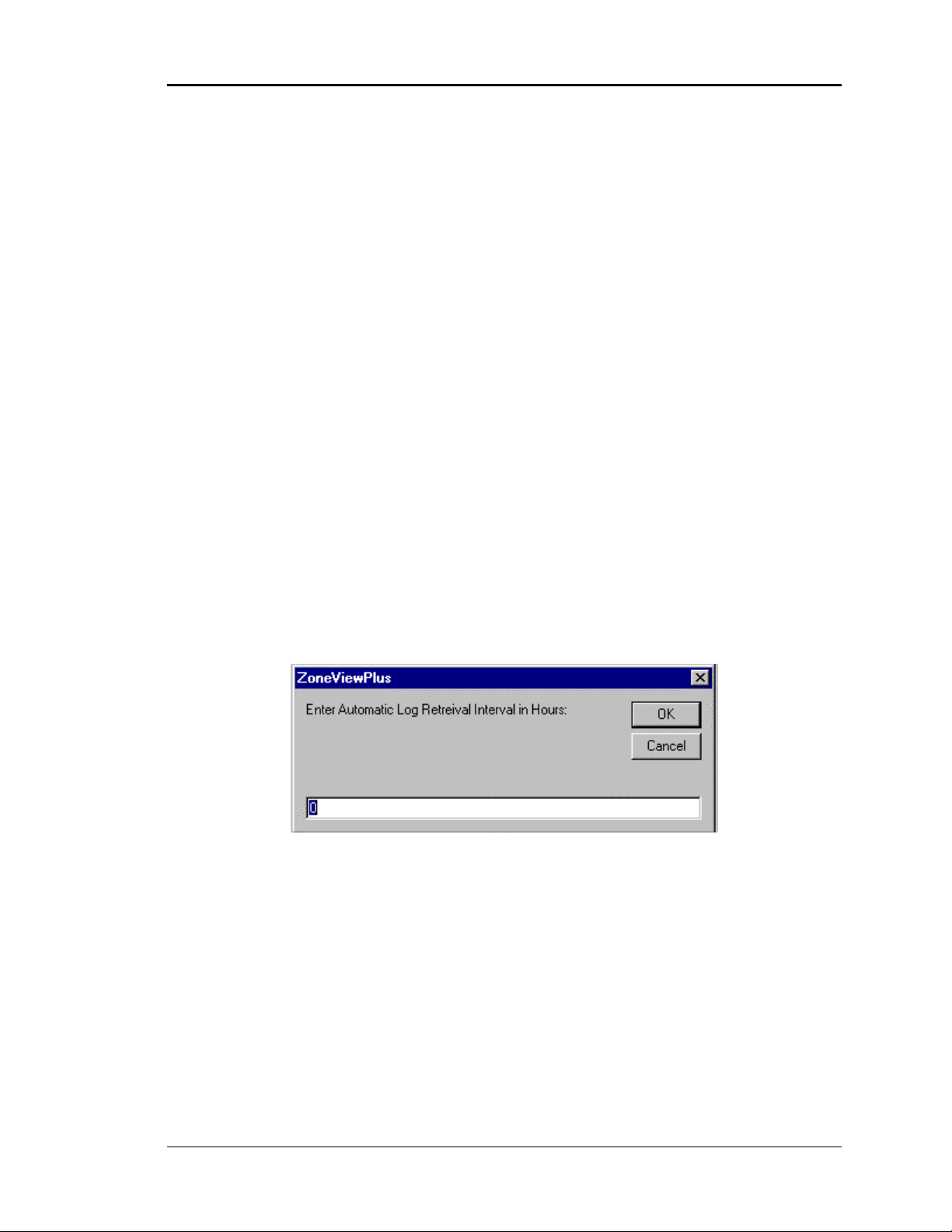
AutoLog Interval
If the ZoneView Plus program is left running continuously at the job-site, it can
automatically poll each installed unit for its’ internal trend log data at a predefined
interval. This allows you to save important trend log data to disk for later review and
prevents loss of trend log data in case you neglect to manually retrieve the data yourself.
Enter a ZERO if you don’t require automatic retrieval. Otherwise, enter a value between
1 and 120 hours.
If you want to load the logs from all attached units on a one time basis without manually
going to each units’ Status Screen and selecting that option, then select the Start Auto
Log button to initiate the process.
Trendlogs are described in more detail later in this manual.
Computer Front End 7
Page 14
ZoneView Plus
Standard CommLink
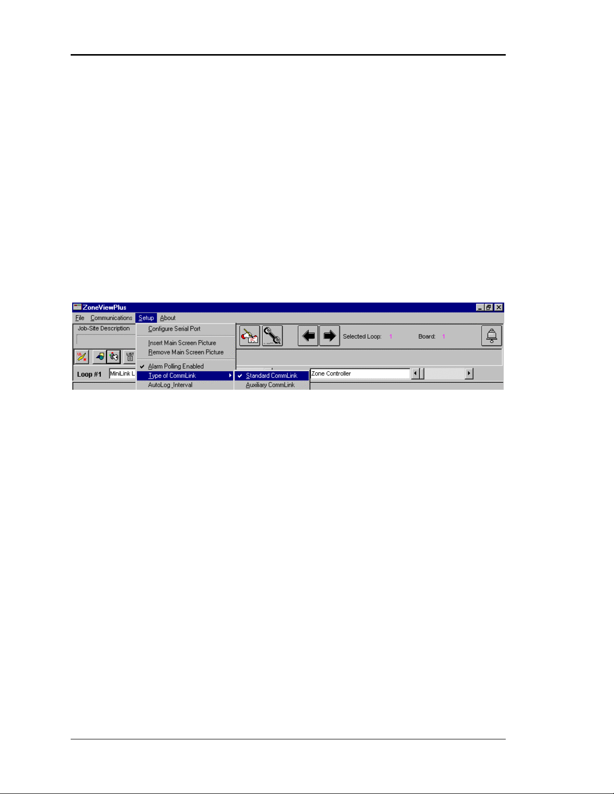
Normally, there will only be one CommLink II interface installed at the job-site. This
enables one computer, located in a central location, to access the entire building or
buildings. One additional computer can be added, if required, by installing an Auxiliary
CommLink device. This Aux CommLink does not support the alarm functions as the
main CommLink does but it allows complete Status and Setpoint access to the entire
installation from a second computer.
If you have installed the Aux CommLink and you are setting up the computer attached to
this device, select the menu item Type of CommLink and the sub-menu item Auxiliary
CommLink. A checkmark will appear next to the currently selected type of CommLink
connection you have just made. If you are using the standard CommLink device, make
sure the Standard CommLink sub-menu has the checkmark beside it.
8 Computer Front End
Page 15
ZoneView Plus
Search For Units
Other ZoneView Plus operations are greatly simplified if the program knows what type of
unit to expect at each address location on the RS-485 communications loop. Before the
user can search for these units the controller installations must be complete and all units
communicating. To access this screen you must have entered your passcode and then
selected the Go OnLine selection located under the Communications menu. The search
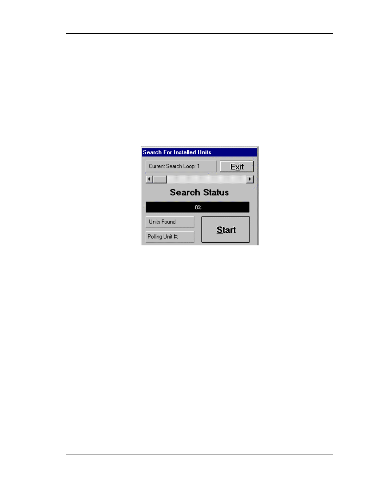
screen is shown below.
Selecting the Search For Units menu assumes that all previous steps have been
completed and you are ready to begin communications with the controllers. This unit
search should be performed the first time you run the program and anytime you add a
new controller or remove a controller from the communications loop. Once this search
has been performed, the identified units will be stored on disk and you won’t need to
repeat this function. Select the Start button to initiate a search.
If you are using this computer to access remote job-sites, then this search should be
performed the first time you call a job-site. These identified units are saved to a file that
is based on the selected phone list number.
Computer Front End 9
Page 16

ZoneView Plus
NOTE: If you are experiencing communications problems, this screen is not the cause
for failure to locate controllers. Lack of communications is almost always a
result of wiring errors or equipment failure, not this Search Screen!
Performing a new search whenever you lose communications with a unit will
cause that unit to be removed from the identified list! That means you won’t
be able to select it from the Unit Selection window. Don’t perform this search
without proper cause!
As you can see on the Search Screen, only one communications loop is searched at a
time. If you have more than one loop of controllers, separated by a MiniLink Interface,
then you will need to select each loop, one at a time, using the Slide Bar. Once the new
loop is selected, start another search by selecting the Start button.
Once a search is started, the Start button will change text and display a Cancel button.
Do not select this Cancel button unless you want to abandon the current search or have
exceeded the address of the last known device on the loop being searched. If you only
have two units on the loop, you can Cancel as soon as address '3' is displayed. The
Search Status percentage bar will show you the progress, as the system looks at all
possible addresses on an individual loop.
Once all units have been found, you are then ready to proceed to actual communications
with the controllers.
A file is automatically saved that contains a list of all known units and any descriptions
the user may have entered for each controller. (See Description Programming ) This file
has a filename that is created by checking to see what the current Jobsite List / Remote
Modem Phone List number is. You can determine what that number is by looking at the
Job-Site Description box in the upper left corner of the screen. The List # is always
displayed in this box. If you want to copy this configuration file and any other files
related to this jobsite to a new computer, use the Export / Import functions found under
the File menu. These functions will be described later in this manual.
10 Computer Front End
Page 17
ZoneView Plus
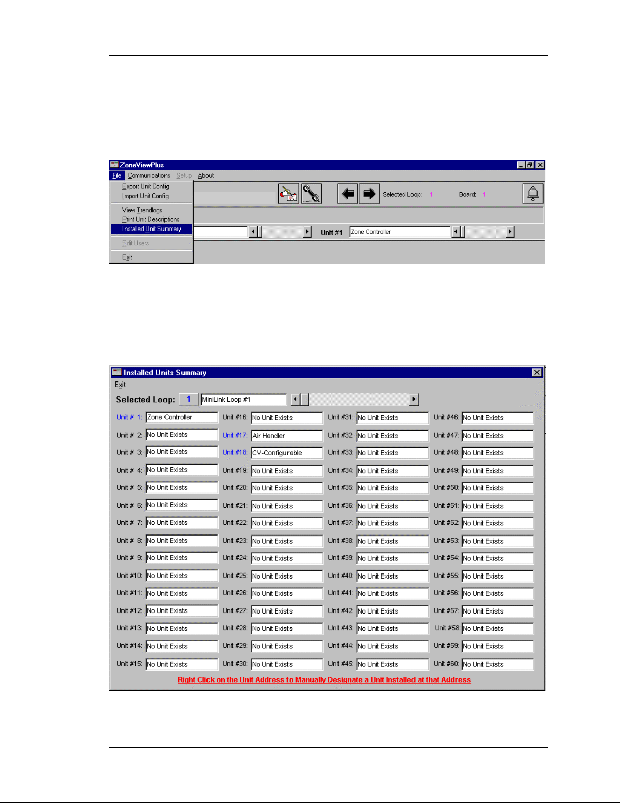
Manually Adding Units
If you are not connected to the jobsite, but still want to configure the units and name
them, you can manually add or delete a unit by accessing the Installed Unit Summary
screen menu located under the File menu.
The Installed Units Summary screen is shown here. Make sure you select the proper
type of controller for the selected address. If you do not, the status screens, setpoint
screens and trend logs and alarm screens will not operate correctly because the data
coming from the controller will not match the improper selection you just made.
Computer Front End 11
Page 18
ZoneView Plus
The screen above shows a Zone Controller resides at the first controller address. This
description can be manually changed to reflect the unit location or whatever other
information you deem appropriate for identifying the unit installed at this address.
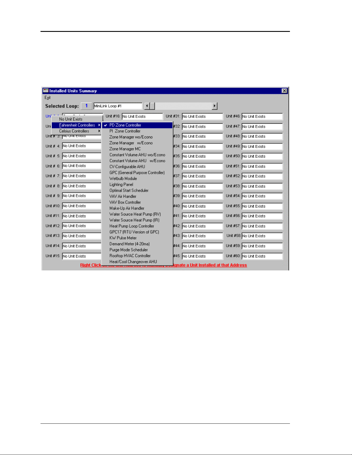
As you can see from the above screen, a window with a list of units popped open when
you right clicked with the mouse on the Unit #1 description. You can see that a
Fahrenheit version of the Pressure Dependent Zone Controller was the selected unit at the
Loop #1, Unit #1 address.
12 Computer Front End
Page 19

ZoneView Plus
Print Unit Descriptions
Once all the units have been configured and a description has been entered, you can print
out a hard copy of all controllers installed on your jobsite. Select the Print Unit
Descriptions item located under the File menu. Only those loops that have controllers
installed or configured on them will generate a print out sheet. The print out shows what
the Jobsite / Phone List number is, the Loop Description you typed in and the Loop
Address.
The bottom half of the page contains the list of 60 possible controllers and any
descriptions you have typed in. If no unit exists or you haven't changed the default
description, you will see the message B01 - No Unit Exists for each controller and the
B01 will change to reflect the board address of the unit not there. For example, address
27 would show B27 - No Unit Exists.
Computer Front End 13
Page 20

ZoneView Plus
Exporting / Importing Unit
Configurations
If you have configured all the controllers and made all the description changes on the
jobsite and you wish to copy this information to another computer, first select the Export
Unit Config item found under the File menu.
The Jobsite / Phone List Number defaults to the one you have currently selected. The
jobsite description is displayed above that number (List #1: Direct Connect) as shown
above.
Make sure you have installed a 1.44 Meg Floppy Disk in drive A: before continuing. It
should be an empty disk for best results.
Exporting Data
If this is the jobsite you wish to copy information from, then select the Begin Exporting
button. All files associated with this selected jobsite will be copied to the floppy disk for
transport to the next computer. Monitor the Status field on this screen to see when the
copying is complete. It will display the word Done. At this time you can select the Done
button if you are finished. If you want to copy another jobsite to floppy you must remove
the disk you just created and install a new floppy disk. This is because you can only copy
one job to a floppy disk. Any old data will be erased if you attempt to put more than one
job on a floppy disk. With the new disk inserted, you can now use the horizontal scroll
bar to select another jobsite for copying. You can repeat this process until all jobs have
been copied.
14 Computer Front End
Page 21

ZoneView Plus
Importing Data
Now that you have the floppy disk or disks containing the required files, take them to the
new computer you are setting up and insert a disk in the A: Drive. Now select the Import
Unit Config item found under the File menu. You must know which Jobsite or Remote
Mode Phone List Number is available to accept a new job. Check under the Telephone /
Jobsite Setup section of this manual for information on how to setup or check existing
jobsites. Once you know which jobsite number you want to import data into, select that
number using the horizontal scroll bar. Once the proper list number is displayed, select
the Begin Importing button. When the process is complete, the Status line will display
the word Done. You can either exit using the Done key or you can import other jobs to
other jobsite numbers. Replace the existing floppy disk with a different jobsite disk and
start this process over from the top of this paragraph.
Copy Phone List
Normally you will not copy the list of phone numbers from one computer to another, but
if you are saving files so that a replacement computer can be setup, you can duplicate the
list of phone numbers by copying the PhoneList.DAT file from the old computer to the
new computer. You can do this using the Windows Explorer. That process will not be
explained here as it is assumed the user already has some familiarity using windows.
If you intend to duplicate all of the existing data on a new computer, it would be easier to
copy all files with the extension CFG, DAT, ALM, XLS ,SPT and SCR from the old
computer to the new computer AFTER you install ZoneView Plus on the new computer
using the installation disks or cd rom.
Computer Front End 15
Page 22

ZoneView Plus
System User Setup
ZoneView Plus supports multiple users at up to 8 levels of passcode security. Only the
user at the System Manager Level has the ability to change or access the database of all
other users. If the system is “Online” you must first go “Offline” .
To access this database, select the Edit Users menu item under the File menu from the
main screen menu bar.
The System Users programming window is shown below:
16 Computer Front End
Page 23

ZoneView Plus
Select the New button before entering a new user. If you type over the existing data, you
are actually changing or editing that current user.
Enter the users Last Name in the first box.
Enter the users First Name in the second box.
Enter the users own personal Passcode in the third box ( Case Sensitive )
Enter the users operating User Level in the fourth box.
Select the Save button when you have finished entering each user.
Select the Delete button if you wish to remove a user from the system.
The User Level is used to prevent unauthorized persons from access to some of the
system critical setpoints or configurations. The System Manager has the ability to set the
passcode level of most setpoints on your system ( see the sample setpoint screen for
information on how this is accomplished ).
NOTE: Due to space limitations, try to limit the maximum number of characters in the
User Names to 20. This will allow room to display the User Name and User
Level at the bottom of the Main Screen.
The System Manager should change the default User Code and Names, if desired, to
prevent anyone else from gaining full access to the system. If the default code is changed,
it is the System Managers responsibility to “remember” the new code or they will be
locked out of the system at the Manager Level!
Computer Front End 17
Page 24

ZoneView Plus
Description Programming
You can name each controller installed on the communications loop with a 20-character
description that makes locating units much easier for the casual system user. There are
two methods of entering unit descriptions. The first method involves opening the
Installed Units Summary screen and entering new descriptions there or, as shown below,
you can edit a unit description right on the main screen. Select the desired Loop or Unit
description box and type in a new name. Once the name is typed in, press the Enter key to
save the new description to disk.
As you can see in the above example, the Unit #1 description is high-lighted and ready
for editing.
All descriptions are saved to file on the computer. If you need to copy this information to
another computer, use the Export / Import feature found under the File menu item.
If you don’t have a unit installed on Loop #1 and Board Address #1 then it is
recommended that you use the Left/Right arrow buttons shown below to select the first
available unit on your system. These arrows only select installed units and skip all
addresses where no units have been configured or detected by the Unit Search method. If
you use the scroll bars, shown above next to the Loop and Unit description boxes, you
can step through every existing address whether a unit is installed or not.
The arrow buttons are useful when you are viewing the status screens and you wish to
move up or down through several controllers that are in sequential order. If you are
jumping across several addresses, it is more efficient to use the horizontal scroll bars to
select the unit.
18 Computer Front End
Page 25

ZoneView Plus
Comm Link II Setup
If this is a Direct Connection setup, you will need to verify or program some settings
into the Comm Link II device. These settings can only be changed by the onsite computer
running ZoneView Plus. If you are installing a remote system, you will need to bring the
Comm Link II device to the remote computer and connect it to the computer serial port
(Not the Modem!). Once the Comm Link II is programmed, you should never have to
perform this function again.
You must have previously configured the correct serial port before attempting this setup.
To perform this setup select the Go OnLine option under the Communications menu
and then select the Setup CommLink menu from the Communications menu shown
below to activate the Comm Link II Setup Screen.
The following Comm Link II setup screen will appear:
When the screen first appears, no data will be present. You must select the Load button
to retrieve setup information from the Comm Link II.
Computer Front End 19
Page 26

ZoneView Plus
Once the Load button has been pressed, the CommLink should return the following
default data shown below. If the CommLink has been previously programmed, then it
will return the programmed data and it may or may not match what you see below.
Setup Definitions
Baud Rate
This must be set to 9600 Baud. That is the only baud rate supported by this
program.
ID Number
A two-digit number used to identify which remote location has been
contacted.
Alarm Callout Phone
Not currently required or used by the ZoneView Plus program. Should be
left blank ( shows None if blank ). If this field is not blank, simply
highlight the current data, press <BACKSPACE> and then the <Enter>
key. This will clear the data. Press the Save button to send it to the
CommLink. To verify that the data has been cleared, simply select the
Load button again to reload the current data. This field should now show
the word None.
20 Computer Front End
Page 27

ZoneView Plus
Alarm Callout Pager
Some users require pager notification whenever an alarm occurs. If that is
the case, enter the pager number here along with the identifying number it
called from so you know who to call back. Pressing the <SPACE BAR>
will also clear this field.
Example: 555 1212,,,,555 1234#
555 1212 is the number to dial
Modem Init String
If you are using any other modem than the one provided by WattMaster
Controls, you may need to change the Modem Init String. If your system
does not answer or transfer data correctly, refer to your modem manual for
the correct settings. The settings provided operate with the York supplied
modem.
,,,, the commas command the modem to pause
555 1234 is the number the modem is calling from
# closes out the pager notification sequence
The Modem Init String shown on the example screen is:
AT S0=1 S7=120 &C1 &D2 X1%E1
WARNING: The number one cause of failure for a remote modem that does not
answer a call from ZoneView Plus is the S0 = 1 command is actually set to S0 = 0: If
it is ZERO the Modem WILL NOT ANSWER!
Once you are satisfied with the Comm Link II settings you must press the Save button to
force ZoneView Plus to send the new settings to the Comm Link.
If this is a Direct Connection system you will need to cycle power to the Comm Link II
device to force it to re-initialize with the new settings. If the Comm Link II was from a
remote location, this will occur when you re-install the device at the remote location.
The maximum number of characters available for phone numbers and the modem init
string is 28 characters.
CAUTION: If you neglect to type in the letters AT at the start of the Modem Init
String, the CommLink II will ignore the modem init string. You must
use the AT command to get the modems attention!
Computer Front End 21
Page 28

ZoneView Plus
Telephone Setup
If this computer is not located at the jobsite, you can use ZoneView Plus to dial through a
modem connected to the computer to the modem connected to the CommLink II at the
remote site. You can keep a list of remote phone numbers and site descriptions by
selecting the phone list editing icon and using the following screen to edit these items.
To edit any field on the screen, simply double-click with the left mouse button on the
desired field and an editing Text Box will pop open at the bottom of the screen.
As you can see, the sample shows that the user selected the Location description for the
first phone number to edit. Click once in the text box to activate the editing cursor and
then you can enter or delete any text you wish to. You should limit your descriptions to
30 characters.
22 Computer Front End
Page 29

ZoneView Plus
You enter or edit the phone number in the same manner. An editing box will appear in
the same location shown. Phone numbers are also limited to 30 characters.
Always press the ENTER key after typing in new data, not only on this screen but on any
screen you are currently using in ZoneView Plus!
You don't have to actually dial a site to make custom screens or description changes. Just
activate this screen and single click on the desired jobsite. When you select the Done
button, the program will clear the list of units on the left side of the screen and load the
units configured for the selected jobsite. You are now ready to work Off-Line from the
jobsite.
Notice the second jobsite shows the word DEMOMODE as the location description. If
you want to see what types of controllers can be accessed by ZoneView Plus or you want
to demo the program to a customer, simply select one of the empty jobsite locations on
this screen and type in DEMOMODE for the location description. The program will
automatically configure one of each type of controller using the first few controller
addresses. When you select a controller for viewing, no communications will occur but
all status and setpoint screens related to that unit will be available for viewing.
CAUTION: You should NOT use the first jobsite location for demo mode if this is
an actual operating system unless you don't mind the inconvenience of
having to manually select a different jobsite location each time you start
the ZoneView Plus program. If this program is installed on a computer
used strictly for demo mode, then by all means, use the first jobsite
location as a DEMOMODE.
Computer Front End 23
Page 30

ZoneView Plus
Dialing Remote Job-Sites
To initiate a dialout to a remote job-site, perform the following items:
1. Access the phone list editing icon shown in the previous section.
2. Single click with the mouse on the phone number you wish to dial.
3. Select the Done button to close out the editing window.
4. Select the Dial-out button shown above to begin dialing.
Select this button to initiate the dialing sequence.
Select this button to abort the dialing sequence.
Select this button to terminate the connection at any time.
24 Computer Front End
Page 31

ZoneView Plus
Accessing Units
To begin viewing Status Screens, select the Go OnLine item under the Communications
menu if this is an on-site computer. Otherwise, simply dial the number as described in the
previous section. The Go OnLine menu is shown below:
Once you select Go OnLine, the communications port is opened and the program begins
all background communications such as Alarm Polling if it has been enabled. To access
the status screen select the View Status Screen item under the Communications menu.
Select the Update Status Screen icon to initiate Direct Onsite Communications
If this is an on-site computer you can also begin communications simply by selecting the
Update Status Screen button located in the upper toolbar. The program will
automatically enter the OnLine mode and the status screen will load and begin to update.
Computer Front End 25
Page 32

ZoneView Plus
Some programming functions and other operating functions such as viewing trend log
files can only be performed while the program is not communicating. Select the Go
OffLine button to terminate communications and enable some of these other features.
The correct status screen will be displayed for the unit originally detected during the
Search for Units during the configuration setup.
NOTE: If you have not configured any units manually or by using the Search for Units
function, no status screen will appear because the program does not know
which screen to load until you configure the type of unit at the selected
address.
If a unit was originally detected at the selected address but it is no longer communicating,
the Status Screen will still appear for that unit but no data will fill in.
26 Computer Front End
Page 33

ZoneView Plus
Sample Screens
Since all status and setpoint screens operate in the same manner no matter which type of
controller you are viewing, this manual will present a sample group of screens and what
to expect on these screens, but it will not display each individual screen contained by the
ZoneView Plus program. If you want to see sample screens, create a DEMOMODE job
site and access the various controllers to see what they look like.
Zone System Status Screen
On most status screens, the most critical temperature is usually displayed in a larger
format than the rest of the data for easier monitoring.
If there are any alarm conditions the MANAGER ALARMS Alarm Bell will be red.
Select the diagnostics button from the toolbar to access this screen.
On some controllers you can override the scheduled mode of operation to Occupied,
Unoccupied or Fan Only Mode. If the unit supports this, you can access the force mode
Computer Front End 27
Page 34

ZoneView Plus
selection by clicking on the box displaying the current mode. A window will pop up
showing the possible selections. If an input or a relay is configurable, clicking on the
display for the desired input or output will activate a configuration window. If a passcode
is required to access any of these features, you will be notified by a message box if you
attempt to change something without the proper access level. Most items accessed from
the status screen require a level 7 or higher access code.
All other setpoints or configurations are generally accessed using one of the buttons on
the toolbar, located right below the menu items at the top of the screen. These buttons are
described in detail below.
Toolbar Button Descriptions
Force immediate upload of data on existing Status Screen.
Custom Screen Editor if Off Line or Load Custom Screen if On Line
Activate Passcode window to log on or off the system.
Access the Installed Unit Summary Screen directly with this button.
Broadcast the Computer’s Time & Date to all installed controllers.
Program Selected Controllers Week Schedules.
Program Selected Controllers Holidays.
Program Selected Controllers Setpoints.
Configure / Program Selected Controller ( Controlling Sensor, Calibrations, etc. )
Enable / Disable individual alarms available on selected controller.
Retrieve trendlog from selected controller.
View Diagnostic Screen of selected controller. ( Powerups, starts, runtimes, etc. )
Send text based version of status screen to laser or inkjet compatible printer.
Exit the status screen.
The next few pages describe the function of each of these buttons in greater detail.
28 Computer Front End
Page 35

ZoneView Plus
Force Immediate Upload
If a status screen is currently being displayed and you want to force an immediate upload
of data from the controller, select this button. The status screen dynamically updates
every 10 seconds, so this button is generally not required. In some instances, if you make
a configuration change that would have an effect on the status screen, you can select this
button to re-initialize the status screen to reflect the configuration changes. For example,
on the sample Zoned System screen shown previously, you might configure the AHU to
not control the Economizer. If you do select this option, the economizer bar graph will
not appear on the status screen. This helps to avoid confusion by displaying only those
items under our control.
Custom Screens
If you want to edit or create a custom floor plan or summary screen or maybe include a
bitmap of your equipment you can select this button when the communications is not
active. That means the Communications menu will be showing Go Online instead of the
message Go Offline displayed while status screens are active. If you want to actually
view your custom screen with live data, then you would select this custom screen button
while communications are active. The custom screen operations will be described in
more detail, later in this manual.
Broadcast Time
Select this item to update the real time clock located on the controller. The time and date
of the selected controller are normally displayed on the status screen. If you select this
item, the following window appears. This window gives you the opportunity to abort the
procedure if you are calling a different time zone and you forgot to change the computers
time to match that time zone.
The computers time and date are displayed in the lower right corner of the computer
screen if you haven't de-activated the Start Menu.
If you are calling in remotely and you are in a different time zone, you will need to
change the computers time before performing this operation.
Computer Front End 29
Page 36

ZoneView Plus
Week Schedules
If you are using the internal scheduling capability of the controller, you will need to
program the starting and stopping times for the Occupied Mode of Operation. The screen
shown below allows you to perform that function.
• The bar graphs on the right side of the screen give the user a visual indication of
the operating hours during a 24-hour period for each day of the week.
• Two Start/Stop events per day are available.
• To eliminate a schedule from any event, simply enter a ZERO for the Start and
Stop time for that day and the screen will then show 12:00 AM for both the Start
and Stop times indicating that the equipment will not activate that day.
• If you want the equipment to run the full 24 hours, enter ZERO to set 12:00 AM
for the Start Time and enter 11:59 PM for the Stop Time. This insures the full 24hour period will remain in the occupied mode. If you run 24 hours per day, every
day, you would set these start/stop times and the equipment would never turn off.
(No one minute gaps occur at midnight).
• You can Save or Copy the data from this schedule screen to disk and then Load or
Paste it to another controller using the same operating hours by selecting the
desired option under the Save/Restore menu. If you have several similar units
installed on your system, you can select the Copy Schedules to All Units menu
and all units on all loops that are the same type of controller as the currently
selected controller will be set to match this schedule.
30 Computer Front End
Page 37

ZoneView Plus
NOTE: If you copy the schedules to all similar controllers, the holidays are also
copied. There is no way to keep these two items separate even though they are
programmed on different screens. The same will apply when you access the
Holiday Programming screen. If you copy the holidays to all controllers, the
schedules are also copied.
The sample screen on the previous page shows a schedule that can handle two separate
start/stop events per day. Some controllers only support a single start/stop event so the
screen will only show the one start/stop column instead of both columns. The second
event bar graphs are always displayed in a different color on the right side of the screen
than the first event schedules. You should always use the first event schedules and then
the second event if needed. In other words, if you only have one start/stop event per day
then it should be programmed as the first event.
The Save/Restore menu allows the following functions:
Save to Disk Use this to keep a permanent record of the schedule
for each controller. This allows you to recover the
data from file in case you ever need to replace the
controller.
Load From Disk Use this to load the permanent record you created
using the Save to Disk item.
Copy Setpoints For a temporary Cut & Paste operation, select this
item to copy the data to a temporary file.
Paste Setpoints After you have selected another controller, you can
use this to paste the data from a previous controller
to the new controller with data you created using
the Copy Setpoints item.
NOTE: Please remember how the Save/Restore menu items are utilized or refer back to
this page as these functions won’t be described again in this manual. They are
available on Holiday programming and Controller Setpoint screens along with
the Week Schedule programming screen.
Computer Front End 31
Page 38

ZoneView Plus
Holidays
If your job-site has days during the year where you need to override the standard
operating hours to accommodate Holidays or other special events, you can use this screen
to select which days are considered Holidays.
The Holidays are configured or entered with the assumption there is a Starting Day and a
Stopping Day. If only one day is required, then that day is perceived as both the Start and
Stop days. If you need several days in a row, then all consecutive days selected are
viewed as a single holiday event that starts on the first day in the group and ends on the
last day in the group. If your holiday crosses a weekend, then you must select Saturday
and Sunday as part of the holiday also. There are 14 possible holiday Start / Stop events.
If you exceed this number, they will be ignored and only the first 14 will be retained. A
holiday is selected by using the left mouse button and clicking on the desired day or days.
The selected days will turn yellow to indicate they are part of a holiday. The same Save /
Restore menu selection is available for holidays as was described under Week Schedule
programming.
NOTE: Holidays can only be programmed for the current year. You cannot program
holidays before the next year occurs.
If your selected controller is limited to eleven single day holidays, the same screen will
appear but the operation will be limited to testing for a maximum of eleven days selected.
That means if you have a two day holiday, like at Thanksgiving, that counts for two
holidays instead of one on the start/stop style of holidays.
32 Computer Front End
Page 39

ZoneView Plus
View/Change Setpoints
If the Setpoints ICON is selected the user can modify the operation of the selected
controller. Each setpoint is passcode protected, so unauthorized users cannot
inadvertently change the operation of the system.
If the user is operating at the System Manager passcode level, they can set the passcode
access level of each setpoint on this screen. Move the cursor over the description box for
each setpoint and press the RIGHT mouse button. The following box will pop open
which allows the user to change from the default level 8 access to whatever is desired for
that setpoint.
Computer Front End 33
Page 40

ZoneView Plus
A brief description for each setpoint is available on screen. Simply locate the cursor over
the desired setpoint and press the RIGHT mouse button. This will cause a message box
to pop open with a description of what the selected setpoint is used for. No setpoint
descriptions will be provided in this document.
All setpoints shown on the following pages can utilize the Save / Restore functions
described in the Week Schedule programming section.
34 Computer Front End
Page 41

ZoneView Plus
Shown below is a sample of how the Zone Controller Setpoint screen appears. Notice that
you must ALWAYS press the <Enter> key after you type in a new value or it will not be
sent to the controller!
As mentioned earlier, not all setpoint screens look alike because of different setpoints for
different types of controllers, but they all operate in the exact same manner when it comes
to help screens and setting passcode levels.
Computer Front End 35
Page 42

ZoneView Plus
Configuration Screen
As you can see from the sample configuration screen below, this is where you decide
things like which sensor will control the Zone Controller and other options that are
normally selected by checking a box or option button. Since the configuration screen
selections are generally based on a single selection from a group of options, each option
is not individually passcode level programmable like the setpoints that are generally
typed in by the user at the keyboard.
36 Computer Front End
Page 43

ZoneView Plus
Diagnostics Screen
From this Diagnostics Screen you can view the all of the Zone Manager and Zone
Controller alarm conditions and the individual start counters for all relays.
Reset Counters
Select this menu to reset any of the available diagnostic counters or run-times back to
zero. Not all screens have this same mechanism, but if the ability to reset diagnostics is
present, it will appear under a menu similar to this one.
You can’t clear an individual starts or runtimes, but you can clear just one or the other or
both to get a fresh starting point for troubleshooting the system.
Computer Front End 37
Page 44

ZoneView Plus
Load Trend Log from Unit
Each controller maintains its own internal log of all available temperatures and control
output conditions. Select this item to load the log data from the controller to a file on the
hard disk. The file will be named using the Loop and Board Address of the selected
controller for later retrieval. The data is stored in an EXCEL spreadsheet which means
you must have EXCEL installed on your computer to utilize the trend log features.
CAUTION:This program has been verified to operate with a standard Office 97
installation of the Excel program. Office 2000 installs it's files in a
different directory structure and is not yet supported by this program.
The log files are not displayed when you load the data from the controller. Watch the
bottom left status bar to determine when the log is fully loaded and saved. To view the
log data you must exit the status screen back to the main screen and then access the View
Trend Logs item from the File menu. EXCEL will be launched and you can use the File
Open method and direct it to the ZoneView Plus directory to look for spreadsheet files to
load. Once loaded into EXCEL, you have the full power of EXCEL to sort, delete old
data, create graphs or perform any other function within the capabilities of the EXCEL
program.
NOTE: It is assumed the user is familiar with the operation of the EXCEL™ program
and therefore support from Wattmaster Controls is not available for users
operating this option.
The data is stored in a filename created by using the Loop and Unit Address of the
controller you wish to view.
For a computer at the job-site, the filename for the first unit on Loop #1 would be:
OnSiteLog0101.LOG
The 0101 indicates Loop #01 & Unit #01.
If you had called in from a remote computer, the filename would be:
RemoteLog0010101.LOG
The 0010101 indicates Phone List #001, Loop #01 & Unit #01.
38 Computer Front End
Page 45

ZoneView Plus
If you had more than one communications loop and several units on each loop, the
numbers would change to indicate the selected unit.
Example #1: You saved data with the on-site computer for the 5th Unit on the 3rd Loop.
The file created would be named: OnSiteLog0305.LOG
Example #2: You saved data with a remote computer. You selected the 6th phone
number from your phone list of remote job-sites and you selected the 15
th
Unit on the 2nd Loop.
The file created would be named: RemoteLog0060215.LOG
The data is sorted and stored in chronological order with the oldest data first. You are
limited to the number of rows that EXCEL is capable of supporting, so if you tend to
gather lots of trend logs, you will need to perform periodic maintenance on the file to
keep it from growing too large to add new data to. If you notice the log retrieval getting
sluggish, you should either save the file to a different directory or filename so you don’t
lose any data or simply delete old and out of date data from the file. The larger the file,
the longer it takes to load and sort and then re-save back to disk.
All trend log items found in the spreadsheet have a column header that defines what the
data in that particular column represents. If the column displays Status or Relays, then the
information is generally BIT packed and must be manually extracted.
The numeric values in these bit packed columns are broken out as follows:
Example #1: Relays 1,2 & 3 are active
2 ^ (1 – 1) = 1
2 ^ (2 – 1) = 2
2 ^ (3 – 1) = 4
1 + 2 + 4 = 7 Relay Status would show a value of ‘7’ in this case.
Example #2: Relays 1 & 4 are active
2 ^ (1 – 1) = 1
2 ^ (4 – 1) = 8
1 + 8 = 9
Staging would show a value of ‘9’ in this case.
Computer Front End 39
Page 46

ZoneView Plus
Alarm Enable/Disable
Alarms are always displayed on the controller status screen and can't be disabled from
appearing there. Alarms can also be collected all at one time through the CommLink II
interface and an alarm callout can be created if the CommLink has had a Pager Number
programmed into it. See the previous section on setting up the CommLink II Device.
The sample screen below shows all of the alarms on this device that can generate an
alarm callout if they are enabled. You can enable or disable any of these alarms to prevent
nuisance alarms when you know the equipment has a problem, or if you simply don’t
require the notification.
If there is an ‘X’ in the box to the left of any line, that condition will be allowed to
initiate an alarm notification process.
40 Computer Front End
Page 47

ZoneView Plus
Alarm Polling
The ZoneView Plus program can be configured to automatically poll the Comm Link II
device, every 60 seconds, to see if any new alarms have been detected. If a new alarm has
come in, the alarm is logged to a file on disk. The alarm will also cause the alarm bell to
turn red and begin an animated ringing motion to attract the users attention. If the user
clicks on the Alarm Bell they can access the alarm log showing all alarms that have been
detected and whether they have been acknowledged or not. From this screen, a level 8
user can acknowledge the alarms. If an alarm that was just acknowledged still exists, it
cannot be reported again until the condition has cleared and then returned again. If the
ZoneView Plus program is exited, with alarms still showing, and then restarted, the same
current alarm conditions will be reported again. If the alarms are acknowledged then the
Alarm Bell will stop ringing and return to its’ normal gray color. You can still access the
alarm log by clicking the Alarm Bell button.
The alarms reported on this screen cover all units installed at the job. Don’t confuse this
alarm report with the Status Screen alarm messages, since the Status Screens can’t
display multiple alarm conditions from several units.
Computer Front End 41
Page 48

ZoneView Plus
Sample Alarm Status Screen
If an alarm has been acknowledged, it will have an ‘X’ in the first column. This log can
store up to 1000 alarms before you must start deleting old alarms or you can copy this log
to a backup directory and let ZoneView Plus create a new alarm log from scratch.
The Date and Time are recorded when ZoneView Plus actually polls and receives the
alarm condition. It does not accurately reflect when the alarm occurred unless ZoneView
Plus is left running continuously and can log the alarms as they come in. The Loop
column indicates what MiniLink address is on the communications loop the controller is
installed on. If this is a single loop system with only a CommLink II device, then the
Loop address will always be '1'. The Unit column indicates the controller address where
the alarm occurred. The descriptive name for that controller, entered by the user, is
displayed in the Name column. The Alarm column indicates what the actual alarm
condition is.
If you examine the sample shown above, you will notice that Unit #1 on Loop #1 had a
Mechanical Cooling Alarm. This alarm also shows that the user has acknowledged the
condition.
To delete old records, simply select the rows you want to delete by positioning the cursor
on the first row you want to delete. Depress the left button and while holding the button
down, drag the cursor down to the last row you want to delete. The first row you selected
will have the focus box surrounding it (see first row and box above) and the remaining
rows will have a blue background. You can now access the Delete Selected item under
the File menu and the selected rows will be cleared if you answer yes to the "Are You
Sure?" question that pops up first.
42 Computer Front End
Page 49

ZoneView Plus
Terminal Mode
In some cases you may need to perform low level diagnostics on the equipment under the
supervision of the factory customer service department. If you are asked to access the
Terminal Mode, use the following menu selection. You will need a System Manager level
passcode to access this screen.
The terminal screen will appear in the right hand section of the main window as a white
panel that will normally be empty. The customer service personnel will then tell you what
steps to perform.
CAUTION: Do not access this screen without supervision or unless you have been
trained on how to use it. Access through this screen could cause
equipment operation problems or communication problems!
Computer Front End 43
Page 50

ZoneView Plus
Load Tenant Logs
If you have VAV Box Controllers you have the ability to save tenant override data. This
data contains the date of each override occurrence and the duration for that day. A
running total of override time for the month is maintained in each of these controllers
also. To retrieve the tenant override log data, select the Load Tenant Logs item found
under the Communications menu. ZoneView Plus will automatically search through all
possible controller addresses and whenever it finds a unit that can contain a tenant log, it
polls that unit for its tenant data.
Tenant Logs can only be sent to the printer. There is currently no mechanism for saving
this data to a file.
Start AutoLog
See the sections labeled Alarm Polling Disabled and AutoLog Interval for more
information about automatic trend log retrieval. This Start AutoLog menu item allows
the user to initiate a retrieval of all controller trend logs without having to wait for the
next auto log to occur. This menu item is also handy for retrieving all controller logs at
the same time after you call the remote site. You normally don't enable Auto Logging on
a remote job since you are not continuously in communication with the jobsite.
If you only want to retrieve a log from a single controller, do not use this option. Go to
the status screen for that controller and select the trend log download button from the
toolbar to retrieve a log for just the selected unit.
In either case, these logs are saved in EXCEL™ spreadsheets for later access by the
EXCEL program.
CAUTION: Any time ZoneView Plus initiates an autolog retrieval or you initiate a
manual retrieval, don't attempt to perform other functions with
ZoneView Plus until all logs have been retrieved. This is a very
intensive procedure and all the computer time is used up handling this
function.
44 Computer Front End
Page 51

ZoneView Plus
Download Code
This option was provided for factory service technicians and as such is not used by the
customer unless directed to do so by customer service personnel. Nothing harmful will
occur if the user opens this window, and no operating changes will occur without special
code in the controllers.
About Window
Factory contact information is provided here along with the current version of the
program, which you may need to relate to customer service personnel if you call with
questions. The latest version of the program is generally available on the WebSite shown
at the bottom of the screen.
NOTE: Although newer versions of the program may appear occasionally on the Web
Site, it is usually not necessary to upgrade your program unless you have
experienced a problem and have been instructed to do so by service personnel.
"If it ain't broke, don't fix it!"
Computer Front End 45
Page 52

ZoneView Plus
Custom Screen Creation
ZoneView Plus allows the user to create simple floor-plans or summary screens or
possibly an equipment photograph with temperatures overlaid on the equipment. Not all
status fields on the standard status screens are available on custom screens. You can place
temperatures, damper positions or pressures as a general rule. Items such as relay or fan
status or day / night modes of operation cannot be placed on this screen. The creation of a
sample screen will now be shown in the order that items were placed on the screen.
This is the editor shown before any parts or pictures are placed on the screen. Notice that
the only difference you can see for now is a different set of buttons on the upper tool bar.
This screen was accessed by selecting the Custom Screen Edit button described earlier
in this manual.
46 Computer Front End
Page 53

ZoneView Plus
The first thing we want to do on this sample screen is place a floor-plan that was
previously created using the Windows Paint program. Any graphics editor can be used as
long as the drawing can be saved as a bitmap image. The size of the bitmap is directly
related to the screen resolution you are currently using on your computer. The lower the
resolution (Minimum 800 x 600) the less detail you will be able to place on the screen.
This sample screen was created at a screen resolution of 1024 x 768. Select the button
shown below to place a bitmap on the custom screen:
Load Bitmap Image.
This will open the File Dialog for picture selection.
Notice how all the text has already been placed on the screen while the floor-plan was
being drawn. This allows the user to select any font style, color or size they need and
place them anywhere desired on the screen. If you find something that needs to be
modified on the bitmap drawing after it is placed on the screen, select the bitmap editing
button shown below:
Edit current bitmap.
this bitmap automatically. Once you make the changes, save and exit Paint, it will
reload to this screen with the new changes.
Computer Front End 47
This button will activate the Paint program and load
Page 54

ZoneView Plus
We are now ready to place data fields on the screen. Select the Data Field button and a
box will appear on the screen. Position the cursor over this box, hold the left mouse
button down and then drag the box to the desired location on the screen. When the box is
correctly positioned, you can release the mouse button and it will remain where you
placed it. These data boxes can be repositioned any time you want to after they have been
placed on the screen. Simply repeat the dragging procedure to adjust the position.
Data Field.
For our sample, thirteen boxes were placed on the screen as shown below.
Select this button to place a data box on the screen for placement.
Now we need to identify which unit we will poll for the temperature, what temperature
we want to display and any font or color changes we would like to make to the text box.
To do this, right click on the box and the following pop-up menu will appear.
48 Computer Front End
Page 55

ZoneView Plus
Select Unit
When you drag a data field onto the screen and right click on it, a pop-up menu will
appear with three selections. The first item is Select Unit. You must select which unit
will be polled for the data to fill in this field. The screen below shows a Zone Controller
on Loop #1 and Address #1 was selected.
Once a selection is made, it will be added to the pop-up menu so that you can tell that a
unit has already been assigned to the selected data field.
Computer Front End 49
Page 56

ZoneView Plus
Select Data
Now that a unit has been selected, the program knows what data is available for display
on a custom screen. Click on the Select Data menu to activate the data selection screen.
Since the controller at address #1 was an Auto-Zone Zone Controller, the five conditions
shown above are available for display on a custom screen. We have selected to display
the Space Temperature in the Auditorium.
50 Computer Front End
Page 57

ZoneView Plus
Select Font Color & Size
If the color or font size of the data field needs to be changed, then click on the Select Font
Color & Size menu item to activate the following configuration screen. You can
experiment with the various settings to get the effect you are looking for on your custom
screen. This sample screen uses the default settings.
Once all the data fields have been configured, the custom screen is now ready for access
through the communications port.
Accessing a Custom Screen
Access Custom Screen.
Once the custom screen has been created, it is now ready to load and access the units
defined for each data field placed on the screen. You cannot have the custom screen
editor active while communications are active so if you are still in the editor, exit that
function by selecting the Exit button on the toolbar (Not from the File Menu!).
If you are not currently in a communications mode, select the Go Online item under the
Communications menu to open the communications port. Now select the custom screen
button. The file dialog window will open allowing you to select which custom screen you
want to load. Once the screen is selected and loaded, communications should begin
immediately. The screen updates once every 30 seconds so if you need to refresh the data
more often, you can use the Force Immediate Upload button (see page 28) to cause a
polling to begin immediately.
Select this button while communications are active.
Computer Front End 51
Page 58

ZoneView Plus
Accessing Status Screens from
Custom Screens
While viewing the custom screen, you can access the standard status screen for any
controller defined under one of the data fields. Simply position the cursor over the
desired data field and double click with the left mouse button. On our sample screen, the
Zone Controller / Zone Manager status screen would replace the custom screen. Once you
are finished viewing the status screen and you select the Exit button, you will be returned
to the custom screen. Use the same Exit button on the toolbar if you want to exit the
custom screen.
52 Computer Front End
Page 59

ZoneView Plus
Compatible Controllers
The ZoneView Plus program is compatible with the following controllers:
SS0003 TUC-5R+ Air Handler Version 4.00 & higher
SS0001 TUC-2R VAV Box Controller Version 1.00 & higher
(Also used for Stand Alone Boxes)
SS0019 - SS0024 TUC-2R Zone ControllerVersion 2.00 & higher
SS0011 - SS0012 Zone Manager Version 2.00 & higher
SS0025 - SS0026 TUC-5R Constant Volume AHU Version 2.00 & higher
SS0032 TUC-5R+ Constant Volume AHU Version 1.00 & higher
SS0035 RTU-17 General Purpose Controller Version 1.00 & higher
SS0028-SS0029 TUC-5R Wetbulb Module Version 3.00 & higher
SS0036 TUC-5R KW Pulse Meter Version 1.00 & higher
SS0038 TUC-5R KW Meter (4-20ma) Version 1.00 & higher
SS0030 TUC-5R GPC Version 2.00 & higher
SS0033 RTU-17 Optimal Start Scheduler Version 3.00 & higher
SS0034 RTU-17 Lighting Panel Version 4.00 & higher
SS0037 Zone Manager MC Version 1.00 & higher
Computer Front End 53
Page 60

Notes:
ZoneView Plus
54 Computer Front End
Page 61

Page 62

Form: WM-ZVP-CFE-01C Printed in the USA August 2000
All rights reserved Copyright 2000
WattMaster Controls Inc. • 8500 NW River Park Drive • Parkville MO • 64152
Phone (816) 505-1100 E-mail: mail@wattmaster.com Fax (816) 505-1101
 Loading...