

Page 1
www.wattmaster.com
USB-Link
Technical Guide
USB-Link Code: SS0070
Page 2

Table of Contents
General Information ......................................................................................................................................... 3
USB-Link Overview ......................................................................................................................................................................3
System Requirements ..................................................................................................................................................................3
Quick Guide ...................................................................................................................................................... 4
Connection and Wiring .................................................................................................................................... 5
USB-Link Driver Installation Instructions for Windows XP ............................................................................ 6
USB-Link Driver Installation Instructions for Windows Vista & 7 .................................................................. 8
Finding the COM Port Number ......................................................................................................................... 9
Prism II Setup Instructions ........................................................................................................................... 10
Communication Settings and LED Descriptions ........................................................................................... 12
USB-Link Communication Settings ............................................................................................................................................12
USB-Link LED Descriptions .......................................................................................................................................................12
Troubleshooting ............................................................................................................................................. 13
Troubleshooting T ips ..................................................................................................................................................................13
Troubleshooting the USB Drivers for Windows XP ....................................................................................................................14
Changing the USB COM Port Number .......................................................................................................................................15
Verifying CommLink II, CommLink III, and MiniLink EPROM Software Versions .......................................................................16
WattMaster Controls, Inc.
8500 NW River Park Drive · Parkville, MO 64152
Toll Free Phone: 866-918-1100
PH: (816) 505-1100 · FAX: (816) 505-1101 · E-mail: mail@wattmaster.com
Visit our website at www.wattmaster.com
Form: WM-USBLNK-TGD-01D © June 2011 WattMaster Controls, Inc.
Windows® XP , Vista, and Windows® 7 are registered trademarks of Microsoft Corporation.
WattMaster Controls, Inc. assumes no responsibility for errors or omissions.
This document is subject to change without notice.
Page 3
USB-Link Technical Guide
USB-Link Overview
The USB-Link (OE366) is a portable device that is used as an interface
to connect your computer to WattMaster controllers without the need
for a CommLink.
The USB-Link provides a direct link to enable you to view the status
and confi gure and adjust the setpoints of any controller on the control
system communications loop using Prism II graphical front end computer software.
The USB-Link is small in size and is powered by the USB port of the
computer it is plugged into, making it completely portable and allowing
connection to the system from any controller.
The USB-Link is supplied with a USB cable, a mini-DIN male communication cable, and two mini-DIN to terminal adapters. The communication cable allows you to walk up to any controller that has a
communication socket and plug in the USB-Link to gain access to the
system. The adapters are used for boards that do not have a female
mini-DIN plug connection.
General Information
CAUTION: The USB-Link will not work with Prism software.
It will only work with Prism II software.
System Requirements
To enable the USB-Link to work with Prism II, you will need:
• USB-Link with USB cable, mini-DIN male
communication cable, and adapters for terminal and
modular connections (cables and adapters provided)
• USB drivers on CD-ROM (supplied with USB-Link but
also downloadable from any of our websites)
• PC with USB 1.1 or 2.0 port (supplied by others)
• Microsoft® Windows® XP, Vista, or 7
• Prism II software (supplied with USB-Link but
also downloadable from any of our websites)
Networked Systems Only
• CommLink(s) with software v3.15 or later and/or Mini
Link(s) with software v3.14 or later.
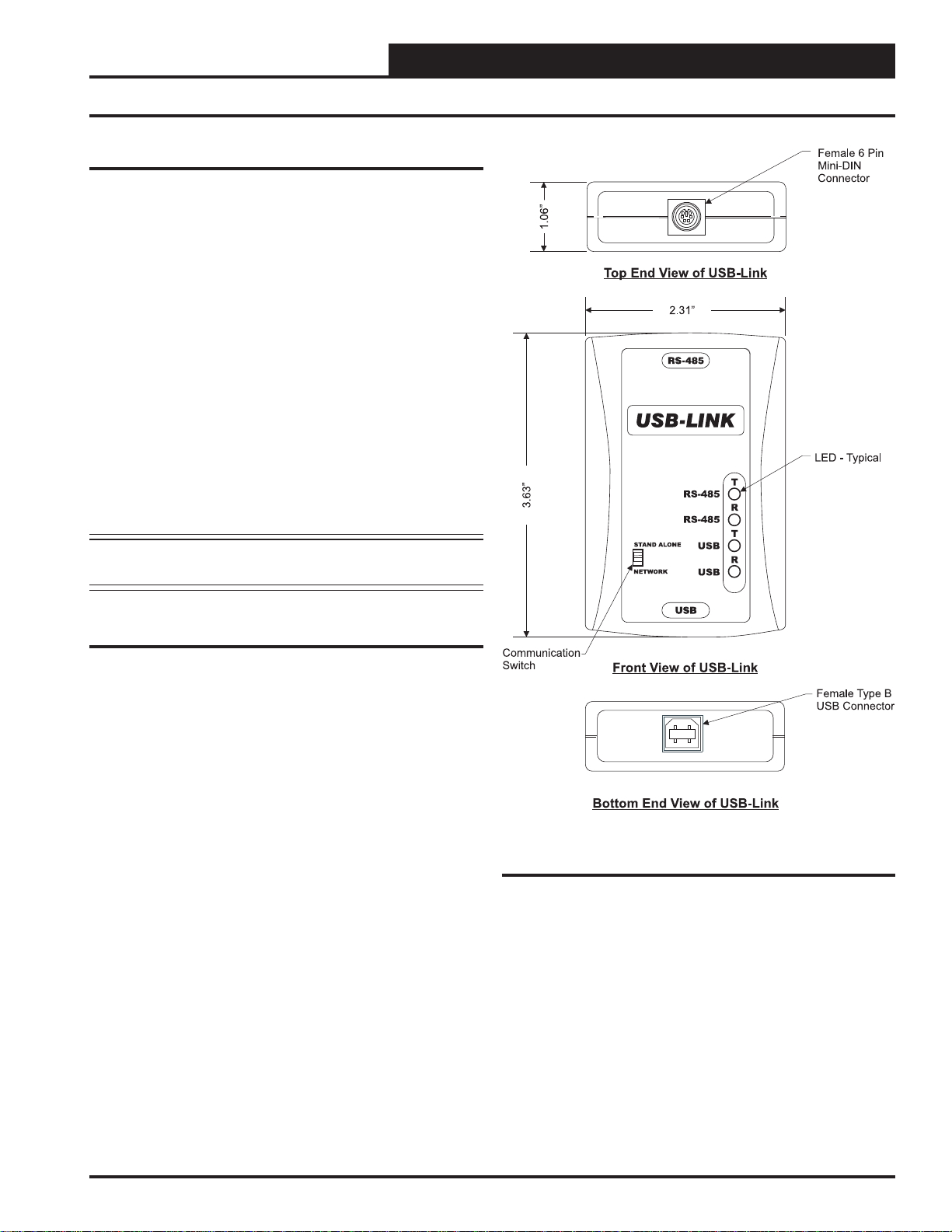
Figure 1: Top, Front, and Bottom Views of the
USB-Link
Please note: If these devices contain earlier software
versions, you will need to order updated EPROMs from
WattMaster. See Troubleshooting on page 16 for further
instructions.
Operator Interface
Revised 1/24/11
3
Page 4

USB-Link Technical Guide
Quick Guide
Important Notes
Follow the included USB-Link driver installation
instructions. Make sure you follow the appropriate
directions for your Windows® version - Windows® XP
directions are different from Windows® Vista.
Follow the connection and wiring instructions
(Figure 2 on page 5) to connect and confi gure the
USB-Link.
If you use your USB-Link on a network and after
installation you cannot view all controllers, you may
need an EPROM upgrade in your CommLink(s) and/
or MiniLink(s). See Troubleshooting in the back of
this guide on page 16 for further instructions.
Familiarize yourself with all system components and
review all documentation. Pay special attention to
“Cautions,” “Notes,” and “Warnings” since these may
keep you from experiencing unnecessary problems.
If you encounter any problems, please refer to the
Troubleshooting section of this guide fi rst. If you
can’t resolve the problem, please call WattMaster
Technical Support at our toll free number—
1-866-918-1100.
Quick Guide for Windows Vista & 7
Follow the fi ve steps below to get your USB-Link up and running in
no time.
Step 1: Set your USB-Link’s communication switch to Stand Alone
or Network. See Figure 3 on page 12.
Step 2: Install the USB drivers from the included CD-ROM onto
your computer.
Step 3: Attach the USB cable to your USB-Link and plug
the other end of the cable into your computer’s
USB port. See Figure 2 on page 5.
Step 4: Attach the communication cable to your USB-Link
and connect the other end of the cable to the
Controller’s communication port. See Figure 2 on
page 5.
Step 5: Install the included Prism II software on your
computer.
Quick Guide for Windows XP
Follow the fi ve steps below to get your USB-Link up and running in
no time.
Step 1: Set your USB-Link’s communication switch to
Stand Alone or Network. See Figure 3 on page 12.
Step 2: Attach the USB cable to your USB-Link and plug
the other end of the cable into your computer’s
USB port. See Figure 2 on page 5.
Step 3: Attach the communication cable to your USB-Link
and connect the other end of the cable to the
Controller’s communication port. See Figure 2 on
page 5.
Step 4: Install the USB drivers located on the included
CD-ROM.
Step 5: Install the included Prism II software on your
computer.
4
Revised 1/24/11
Operator Interface
Page 5

USB-Link Technical Guide
Connection and Wiring
Figure 2: USB-Link Connection & Wiring
Operator Interface
5
Page 6
USB-Link Technical Guide
USB-Link Driver Installation for Windows® XP
USB Serial Converter Driver
Installation for Windows® XP
CAUTION: You must use the drivers on the CD-ROM supplied
with the USB-Link.
NOTE: If for any reason you cancel out of the New Hardware
Wizard before installing the USB drivers or if you
receive an error message during installation, the
drivers will not be installed. You must then install the
drivers using the directions in the XP Troubleshooting
Section on page 14.
1. Plug the USB cable attached to the USB-Link into your
computer’s USB port.
2. Insert the USB Drivers CD-ROM into your CD-ROM
drive.
3. A message should pop up from the toolbar that reads,
“Found New Hardware.” Click on the Found New Hardware Wizard application from the toolbar.
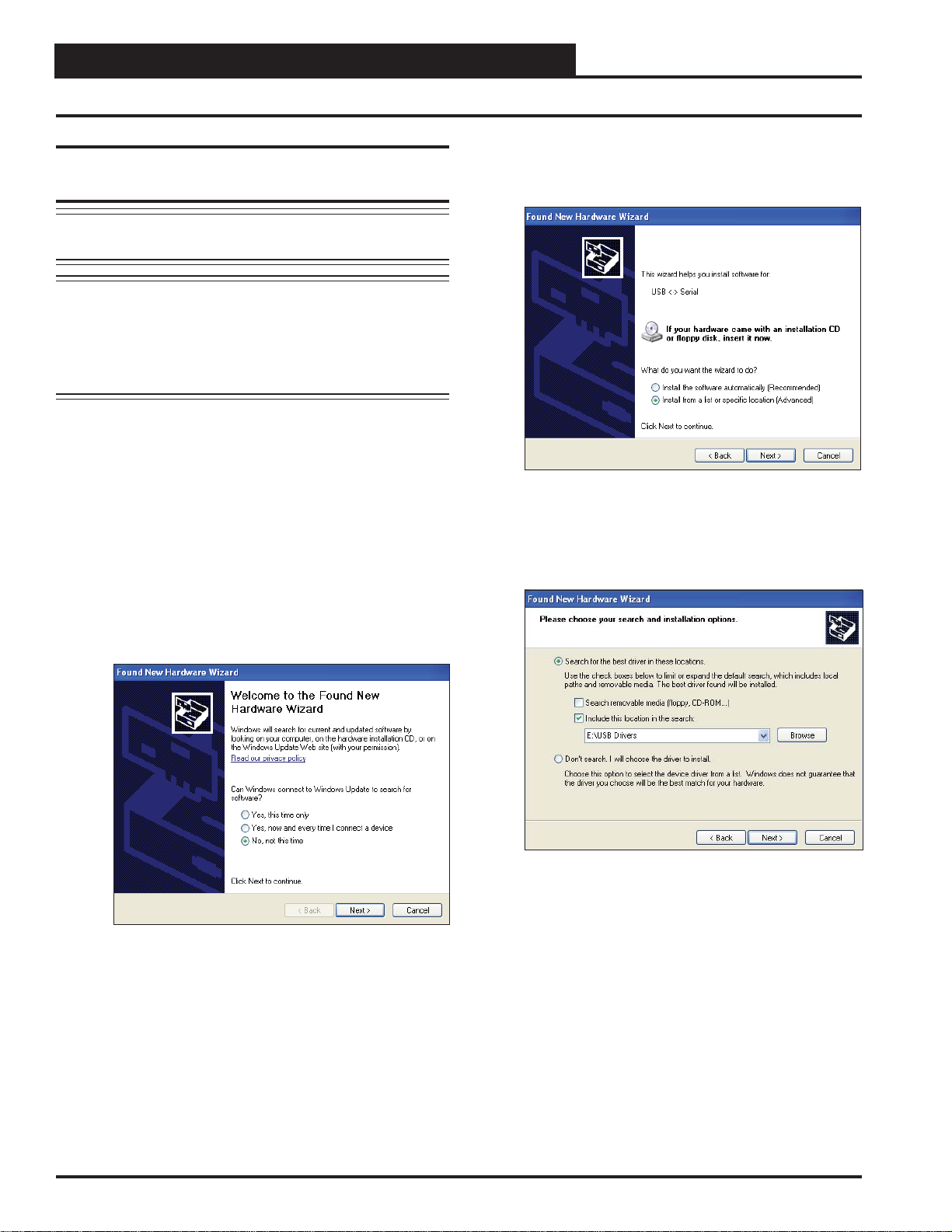
4. The window that appears will ask the question, “Can
Windows connect to Windows Update to search for software?” as shown below. Select “No, not this time” and click
<Next>.
5. The next window that appears will ask, “What do you want
the wizard to do?” Select “Install from a list or specifi c
location (Advanced)” as shown below and click <Next>.
6. In the next window that appears, select the radio
button in front of the option “Search for the best driver
in these locations.” Uncheck the box that reads, “Search
removable media” and instead check the box “Include this
location in the search:”
6
7. Click <Browse> and locate the drive that your
CD-ROM is located on. Click <Next>.
Operator Interface
Page 7

USB-Link Technical Guide
USB-Link USB Driver Installation for Windows® XP
8. Highlight the Win98_Win_2000_WinXP directory by clicking on it and then click <OK>.
9. The screen will now state, “Please wait while the wizard
installs the software...”
10. While the fi les are downloading, a Hardware
Installation Window might pop up as shown below. Click
<Continue Anyway>.
11. The wizard will then fi nish installing the software.
12. Once the wizard is done, click <Finish>.
USB Serial Port Driver Installation for
Windows® XP
1. Once the USB Serial Converter software is installed, the
Found New Hardware Wizard will appear again to download the USB Serial Port software.
2. Follow steps 1 though 7 of the previously described USB
Serial Converter Installation instructions.
3. Click <Finish> when the wizard is done downloading the
software.
4. Windows® XP requires you to restart your computer before
the new settings will take effect.
5. Continue with the next section “Finding What COM Port
Number the USB-Link is Using” on page 9.
Operator Interface
Revised 6/14/11
7
Page 8

USB-Link Technical Guide
USB Driver Installation For Windows Vista & 7
USB Serial Converter and Serial Port
Driver Installation for Windows
Vista & 7
1. Insert the USB Drivers CD-ROM into your CD-ROM
drive or download the USB Drivers fi le from www.orion-
controls.com/software-new.html. If using the CD-ROM, go
to Step 2. If downloading the fi le, click on the USB Driver
Setup.zip fi le to unzip the fi le and then go to Step 3.
2. Double-click on the Vista/Win_7 folder.
3. The WattMaster USB Driver Installation Window will
appear.
4. If you wish to change the Destination Folder, click
<Browse> and change the location. Click <Install> to
install the software. Then, open the WattMaster USB Driver
folder in the temp directory on your hard drive or the new
location if you changed the destination folder.
5. Double-click USBInstaller.exe.
Double-click on USB Driver Setup.exe.
6. Then click the <Begin Install> button.
7. The installation program will walk you through the rest of
the steps. The program might prompt you to remove old
USB drivers from your computer. Click <Yes> if so. Once
installation is complete, you will need to reboot your computer to have the new settings take effect.
8. With successful USB driver installation, you can now connect your USB device.
9. Follow the procedures on page 9 to verify the Comm Port.
8
Revised 6/14/11
Operator Interface
Page 9

USB-Link Technical Guide
Finding the COM Port Number
Finding What COM Port Number the
USB-Link is Using
1. Left-click on <Start>, located on the bottom left of the
Windows toolbar. Select <Control Panel>. Double-click
the <System> icon.
2. Click the <Hardware> tab. Click the <Device
Manager> button.
3. Click on the plus sign next to Ports to see all of the COM
ports.
4. Locate the USB Serial Port (COM#). The COM# in
parentheses is the port it is located on. Write this COM port
number down. You will need to know this when setting up
the Prism II software.
5. If the COM port number is 10 or greater, go to “Changing the USB COM Port Number” in the Troubleshooting
section on page 15; otherwise, continue with the section
“Prism II Setup” on page 10.
Operator Interface
9
Page 10

USB-Link Technical Guide
Prism II Setup Instructions
Confi guring Prism II for the USB-Link
1. Insert your Prism II software CD and follow the prompts to
install the software.
2. The software installation will install the Prism II
icon on your desktop. Click on this icon to open
your Prism II software.
3. Click the <Login> button and type in your
level 3 passcode (default is “9288”).
Click <OK>.
4. If Prism II is online, click the
<ON LINE> button to make it go
<OFFLINE>.
5. Click the <Job-Site> button to open the Job
Sites Window.
7. In the Serial Port fi eld, click on the pull down box and
select the COM port number that the USB-Link is using.
8. In the Type of CommLink selection box, select the radio
button next to USB Link.
9. In the Network Confi guration selection box, select the mode
for the USB-Link you are using. If using stand alone mode,
select USB Link Stand Alone. If using network mode, select
USB Link Network. The position of the slide switch on the
USB-Link must also be set to the mode you are using (See
Figure 3 on page 12 for help in setting this switch).
6. Click on any empty location in the Job-Site Selection
Window and type in a job name in the Selected
Location fi eld. Press <Enter>.
Your job site name will now appear in the Job-Site Selec-
tion Window.
10. Click
11. Click the <OFFLINE> button to go
<Exit> to close out of the Job Sites Window.
<ON LINE>.
10
Operator Interface
Page 11

USB-Link Technical Guide
Prism II Setup Instructions
12. From the <Communications> menu on the main toolbar,
select
<Search for Units>.
13. The Search For Units Window will appear. If you haven’t
performed a previous search, the Loop Selection fi eld
will read 01 and the Current Unit will read 00. You can
perform a selective search by entering the loop number
you would like to search and checking Search ONLY the
Selected Loop. The Check Unit Maps box will already be
checked. Do not deselect this box. Deselecting it will cause
the search not to work.
16. If Units Found on this Loop stays at zero, check the
wiring to the USB-Link and the controller and/or read
through these directions again to make sure all steps were
followed. Refer to the Troubleshooting Section in the back
of this guide for further help.
17. To stop a search, click
18. Once you are done searching for units, close out of the
window or click <Exit>.
19. A window will pop up that asks, “Do you want to save
the search results?” Click <Yes> if you wish to save the
results. Click <No> if not.
20. You can now access any installed unit from the Main Prism
II Screen by selecting a loop from the Loop Selection
Window with a single-mouse click and selecting the unit
from the Unit Selection Window with a double-mouse click.
<Cancel Search>.
14. Click <Start Search> to initiate an automatic
detection of all installed controllers on your system.
15. If everything is working correctly, Units Found on this
Loop should increment. You will also see green boxes
indicating units that have been found.
Operator Interface
11
Page 12

USB-Link Technical Guide
Communication Settings and LED Descriptions
Figure 3: USB-Link Communication Switch and LEDs
USB-Link Communication Settings
The communication switch for stand alone or network mode is
found to the left of the LEDs. See Figure 3 above. To set the
communication switch, insert a pen tip to move the switch up
or down.
NOTE: Whenever you change the communication setting
on the USB-Link, you must cycle the power to the
USB-Link by disconnecting and reconnecting the
USB power supply cable.
Stand Alone - No MiniLink or CommLink - The slide switch
on the USB-Link should be set to “Stand Alone” when you
are trying to talk to a stand alone controller or multiple controllers on a loop without a CommLink or a MiniLink wired
to the communications loop.
Network - MiniLink or CommLink connection - The slide
switch on the USB-Link should be set to “Network” any time
there is a CommLink or MiniLink wired to the communications
loop.
USB-Link LED Descriptions
RS-485 - Indicates communication activity between the
USB-Link and the controller(s) that the USB-Link
is connected to. When both the “T” and “R” LEDs
are fl ashing, data is being exchanged.
USB - Indicates communication activity between the
USB-Link and the computer that the USB-Link
is connected to. The “T” and “R” LEDs will fl ash
only when data is sent from Prism II to the USB Link via USB.
12
Operator Interface
Page 13

USB-Link Technical Guide
Troubleshooting
Troubleshooting Tips
Problems with Prism II Software
• Verify that the correct USB serial port created by the
USB connection is selected in the Job Sites Window.
Verify the COM port number in
<System>,<Hardware>,<Device Manager>,
<Ports>.
• Verify that USB Link is selected for Type of CommLink
in the Job Sites Window.
• Verify that the correct USB Link mode is selected
under Network Confi guration in the Job Sites Window.
Problems with USB Connection
• Verify that the USB LEDs blink when you perform
a Search for Units or try to open a status screen in
Prism II.
• If the USB LEDs fail to blink, disconnect and
reconnect the USB connection.
<Control Panel>,
Problems with RS-485 Wiring
• Make sure T connects to T, R to R, and Shld to Shld if
multiple boards are wired together on a loop.
• Make sure that the USB-Link mini-DIN communication
cable is plugged into a controller or wired to the local
side of the loop.
Problems Viewing Controllers on a Network
• Make sure that in Prism II, USB Link Network is
selected under Network Confi guration in the Job Sites
Window.
• Make sure that EPROM chips in CommLink II and III
are version 3.15 or later and in MiniLinks are version
3.14 or later.
NOTE: WattMaster Controls Technical Support cannot trouble-
shoot internal PC and/or Windows®-based operating
system problems.
• If the problem persists, check that the USB drivers
have been installed properly
Operator Interface
13
Page 14

USB-Link Technical Guide
Troubleshooting the USB Drivers for Windows® XP
Troubleshooting the USB Drivers for
Windows® XP
If the Found New Hardwar e Window did not appear when you plugged
in your USB-Link or if you canceled out of the installation procedure
for any reason, you will have to follow these instructions to install the
USB drivers.
1. Plug the USB cable attached to the USB-Link into your
computer’s USB port.
2. Click <Start>, click <Control Panel>, and then doubleclick <System>. The System Properties Window will
appear. Click the <Hardware> tab and then click
<Device Manager>.
4. Right-click on USB Serial Port and then click <Update
Driver>. The Hardware Update Window will appear.
5. In response to the question, “Can Windows search for
software?” click the radio button, “No, not at this time”
and then click <Next>. Insert your USB Drivers CD-ROM
into your CD-ROM drive. And then click the radio button,
“Install from a list or specifi c location” and click <Next>.
6. The screen will now display the message, “Search for driver
software in this location:” If the location is correct, click
<Next> and go to step 8. If not, click <Browse>.
7. Select the CD-ROM location from the list of folders and
then click <OK>.
3. The Device Manager Window will appear. In this window,
look for an exclamation point in the categories, “Other
devices,” “Ports,” or “Universal Serial Bus controllers.”
Click the item containing the exclamation point.
8. A message will appear that states, “Please wait while the
wizard installs the software...”
9. When the installation is complete, the window below will
appear. Click <Finish>.
14
Operator Interface
Page 15

USB-Link Technical Guide
Troubleshooting the COM Port Number
Changing the USB COM Port Number
When the USB-Link is fi rst plugged in, it will be assigned a COM
port number to be used for communicating with the Prism II
software. If the port number is 10 or greater, it needs to be changed to
a value less than 10 to be recognized by Prism II.
1. Click <Start>, click <Control Panel>, click
<System>, click the <Hardware> tab, and then click
<Device Manager> to get to the Device
Manager Window.
2. Click on the plus sign next to Ports to see all of the COM
ports.
4. To assign a port number less than 10, click on
<Advanced>. The Advanced Settings Window
will appear.
5. In the COM Port Number drop box, select which COM port
you wish to use. Make sure you select a COM port number
that is not currently in use (you can see the ports in use in
the Device Manager Window). Select a port that is less than
10.
NOTE: Windows
has ever been installed on your computer. So if there are
no available ports below 10, choose a port number less
than 10 for a device listed that you know you are not
currently using.
®
will assign a port number to every device that
3. Right-click on “USB Serial Port (COM#)” and select
<Properties>. In the Properties Window, select the <Port
Settings> tab.
6. Once you select the correct COM port number,
click <OK> and close any windows opened in the process
of changing the port number. Make note of this number
because you will need it for your Prism setup.
Operator Interface
15
Page 16

USB-Link Technical Guide
Troubleshooting EPROM Software
Verifying CommLink II, CommLink III,
and MiniLink EPROM Software Versions
In order to view controllers with the USB-Link on a networked system, the CommLink II and III must have version 3.15 software or later
installed and the MiniLink must have version 3.14 software or later
installed. Please follow the directions to determine the current software
version.
NOTE: If you purchased your CommLink II, III, or MiniLink
after January 1, 2007, there is no reason to check the
software version nor is it necessary to check the soft ware version of a CommLink IV.
16
Operator Interface
Page 17

USB-Link Technical Guide
Troubleshooting EPROM Software
Operator Interface
17
Page 18

USB-Link Technical Guide
Notes
18
Operator Interface
Page 19

USB-Link Technical Guide
Notes
Operator Interface
19
Page 20

Form: WM-USBLNK-TGD-01D Printed in the USA June 2011
All rights reserved. Copyright 2011
WattMaster Controls, Inc. 8500 NW River Park Drive Parkville, MO 64152
Phone (816) 505-1100 www.wattmaster.com Fax (816) 505-1101
 Loading...