

Page 1

Graphical Interface
Technical Guide
Page 2

TABLE OF CONTENTS
OVERVIEW ................................................................................................................................... 3
STEP 1: Prism 2 Installation ...................................................................................................... 5
STEP 2: Job-Site Setup ............................................................................................................ 10
STEP 3: Prism 2 Confi guration ................................................................................................ 16
STEP 4: Communication Setup ................................................................................................ 18
STEP 5: Searching For Units ...................................................................................................20
STEP 6: Selecting and Renaming Loops and Units................................................................. 21
STEP 7: Confi guring Units ....................................................................................................... 22
STEP 8: Confi guring Unit Alarms ............................................................................................. 27
STEP 9: Polling For Alarms ...................................................................................................... 28
STEP 10: Trend Logging and Printing...................................................................................... 29
STEP 11: Tenant Override Polling ........................................................................................... 32
STEP 12: Creating Custom Screens ........................................................................................ 33
APPENDIX A - Screen Examples .............................................................................................. 39
APPENDIX B - DEMOMODE Setup and Operation ..................................................................... 41
APPENDIX C - Setting Up Alarm Polling for the System Manager TS ..................................... 42
INDEX ........................................................................................................................................ 43
WattMaster Controls, Inc. 8500 NW River Park Drive · Parkville, MO
64152 Toll Free Phone: 866-918-1100 PH: (816) 505-1100 ·
FAX: (816) 505-1101 · E-mail: mail@wattmaster.com
Visit our web site at www.wattmaster.com
Windows
Corporation.
®
2000, Vista, 7 & 8 are registered trademarks of Microsoft
Form: WM-PRISM2-TGD-01J
Copyright December 2014 WattMaster Controls, Inc.
WattMaster Controls, Inc. assumes no responsibility for errors or
omissions.
This document is subject to change without notice.
Page 3

Prism 2 is a complete Windows®-based graphical interface that
allows you to interact with your WattMaster digital controls.
The program provides standard, easy-to-understand status,
setpoint, and confi guration screens for each type of controller
and has provisions for custom screens which allow fl oor plans,
equipment photos, or user defi ned summary screens.
Prism 2 allows you to access and control schedules, trend logs,
and alarm conditions. The program can be confi gured for direct
on-site installation, remote modem connection, or TCP/IP
Internet connection.
The Prism 2 program is a completely redesigned release of the
original Prism Graphical Computer Interface. This program should
be used on all new installations containing standard WattMaster
Control product families.
NOTE: This manu al is wr itten for a person w ith a working
knowledge of Windows® 2000, Vista, 7 or 8 and does not
describe in detail the process of copying fi les or other Windows®related fu nctions. Lear ni ng the operation of Windows® is the
responsibility of the operator using this equipment.
F eature Summary
OVERVIEW
Fea tures and System Requirements
Minimum Hardware
• Windows
®
compatible computer
• Pentium 2 GHz Processor ( Pentium 4, 2 GHz or
greater, Recommended)
• 1 GB RAM (or greater)
• 120 MB hard drive space
• XVGA (1024 x 768) adapter and monitor
(1280 x 1024, Recommended)
• Network card for TCP/IP connection when IP
Module is used.
In addition, you must have a CommLink (CommLink II, III, IV
or 5) installed on your system or be using a USB-Link in order to
connect and communicate between your computer and the system.
If remote communications to the installation are required, a Remote
Link (Remote Link or Remote Link II) on-site modem (phone line)
or IP-Module (Ethernet) must also be installed.
NOTE: Yo ur W indows
- 100% (default)” found in the Control Panel under Display
Settings. Having the font size set to Medium or Large may cause
Prism’ s graphics to display improperly . See the section, “Setting
Y our Screen Resolution ” on page 4.
®
font size should be set for “Smaller
Software License
Prism 2 does not require any license agreement and may be freely
copied and distributed.
Prism 2 provides a broad set of features:
• Easy to use
• On-site, remote modem, or TCP/IP communications
• User programmable description for every piece of
equipment and user-defi ned custom screens
• Automatic retrieval of trend logs and export
capability to spreadsheet and database programs
• Alarm Logs maintained on disk
• Alarm E-mail capability
• Encrypted History Logs
System R equirements
T o use Prism 2 you must have a computer that meets or exceeds the
following requirements:
Operating System
• Microsoft
NOTE: Prism 2 is not intended for a server/client
environment.
®
Windows® 2000, V ista, 7, or 8
Support Information
W attMaster Controls provides Prism 2 installation and confi guration
support. Call (866) 918-1100 for free, direct telephone support
or (816) 505-1100 to talk to a Technical Support Representative.
Support for all telephone services is available Monday through
Friday, 7:00 AM to 5:00 PM central standard time.
NOTE: WattMaster Controls Technical Support
cannot troubleshoot internal PC and/or Windows®based operating system problems.
NOTE: WattMaster Controls Technical Support can-
not troubleshoot fi rewalls, routers, and/or problems
on a customer’s internal or external network. An IT
professional may need to be consulted.
Prism 2 Technical Guide
Revised 12/01/14
3
Page 4
OVERVIEW
Step By Step Guide
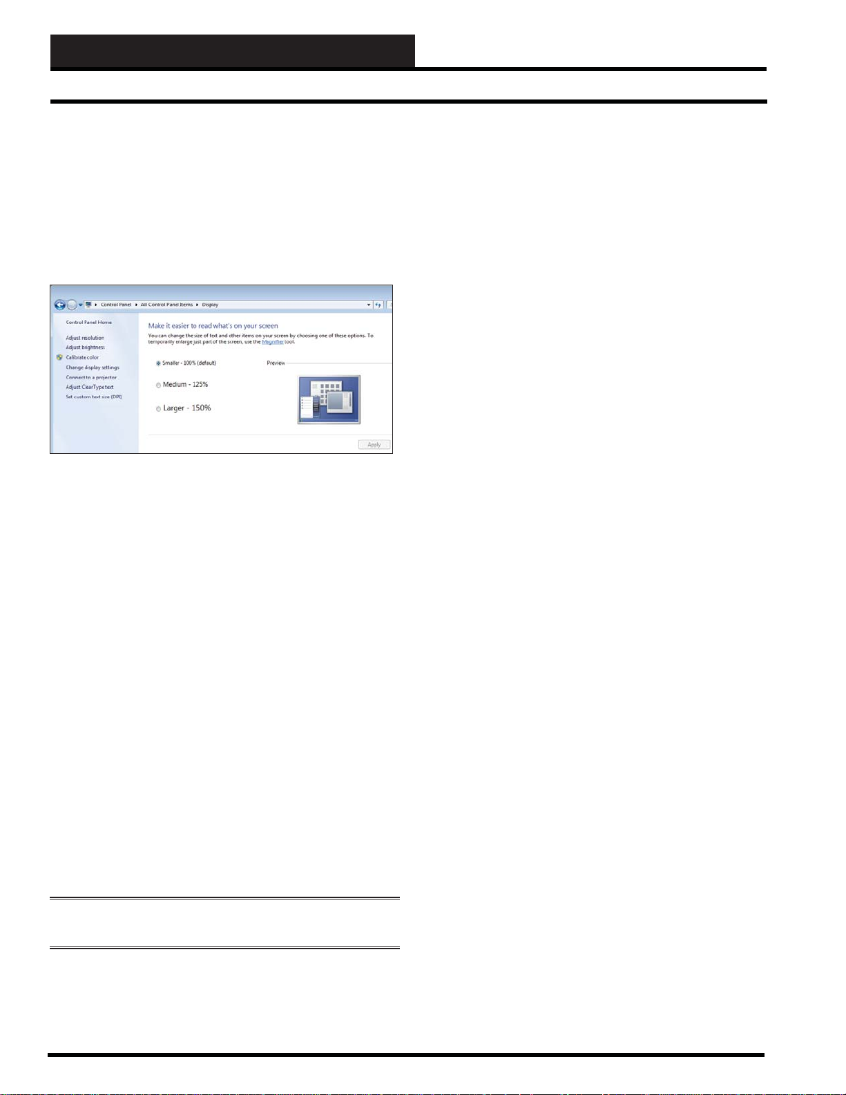
Setting Y our Screen Resolution
In order for Prism graphics to display properly on your computer
screen, your screen resolution must be set to the default which
is small font. If it appears that your graphics are not aligning
properly, verify your system’s font size as follows (directions are
for Windows 8):
Click on <start>, <Control Panel>, <Display>. The following
screen will appear:
Select the radio button for “Smaller - 100% (default)” and click
<Apply>. You will need to Logoff your computer for the changes
to take affect.
T erms and Conv entions
Commands are italicized. For example, the instructions will tell
you to press keys that are found on the keyboard, click or select
buttons and keys that are found on the screens, and enter or type
text.
User input is boldface and enclosed in quotation marks. For
example, you would type the numbers 9288 when the directions
tell you to type “9288.”
All keys, buttons, and menu items that perform a function and
are found on screens or the keyboard are boldface and enclosed
with brackets. For example: press the <ENTER> key; click <Edit
Passcodes>.
Step By Step Guide Map
In order to operate Prism 2 effectively, you should read this entire
guide. This guide will lead you through each step in confi guring
Prism 2—from entering passcodes to searching and selecting units
for troubleshooting. Below is a quick overview of each step.
Step 1: Installing Prism 2—This section explains how to install
the Prism 2 software, initiate communications, navigate the
program, and enter and edit passcodes.
Step 2: Setting Up Job Sites—This section provides instructions
for setting up each job site’s name, port, or IP address, CommLink
type and confi guration, alarm notifi cation, and custom screen
designation.
Step 3: Confi guring Prism 2—This section describes how to have
Prism 2 automatically restart after a power failure and broadcast
time to all controllers. It also explains how to set up the main screen
display picture.
Step 4: Setting Up Communications—This section explains
how to establish communications via modem connection and TCP/
IP connection through your CommLink.
Step 5: Searching for Installed Units—This sections explains
how to perform a unit search per job-site.
Step 6: Selecting and Renaming Loops and Units—This
section explains how to select and rename loops and units.
Step 7: Confi guring Units—This section describes how to
confi gure controller setpoints, schedules, and overrides. It also
explains how to confi gure units while off-line.
Step 8: Confi guring Unit Alarms—This section explains how to
individualize alarm settings for each controller.
Step 9: Polling For Alarms—This section explains how to view,
acknowledge, print, and delete alarms.
Step 10: Logging and Printing—This section explains how to
load, view, and print trendlogs from individual controllers.
Main menus and fi eld names are capitalized and in boldface. For
example, “T ype a number in the Number fi eld.” “You can access
that information from the Communications Menu.”
Screen and window names will always be capitalized and italicized.
For example, “The Search for Units Dialog Box will appear.”
NOTE: You MUST press the <ENTER> key after data entry in
order for the Prism program to accept and save yo ur entry .
Revised 12/01/14
4
Step 11: Tenant Override Log ging—This section explains how
to poll controllers for tenant override logging.
Step 12: Creating Custom Screens—This section explains how
to create Custom Screens containing text, images, and live data.
Appendices—The appendices include examples of status and
setpoint screens, instructions for DEMOMODE and instructions
for setting up alarm polling for the System Manager T ouch Screen.
Index—The index provides page numbers for easy reference to
quickly fi nd the information you need.
Prism 2 Technical Guide
Page 5
STEP 1: PRISM 2 INSTALLATION
Installing Prism 2
Step 1: Install Prism 2 Software
Install From CD-ROM
Step 1: Close out all other programs and applications.
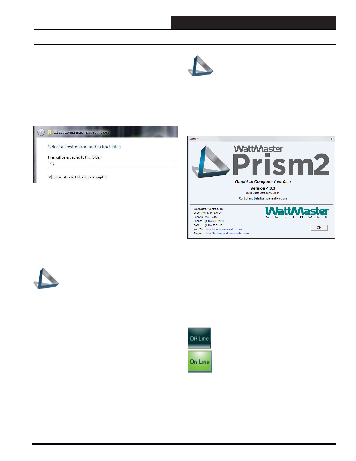
Step 2: Insert your Prism 2 CD into the CD-ROM drive, locate
the PrismII.zip fi le, right-click on the fi le, and select “Extract All.”
Step 3: The Extract Window shown below will open. Type C:\ as
your destination and select <Extract>.
Step 4: The fi les will be extracted to a folder on your C drive
called PrismII. Note: If you already have a PrismII folder at this
location, the program will ask you if you wish to overwrite the fi les.
Select “Yes to All.”
Step 5: Once the fi les are done extracting, open the PrismII folder
on your C drive.
This is how the Prism 2 icon should appear on
your desktop. The background color is determined
by your local computer’s desktop settings.
Verifying Successful Installa tion
Once the program opens, click the “Help” tab on at the top of the
Prism 2 Main Screen and click <About>. The window below will
appear, displaying the version you just installed.
Step 6: Click on PrismII.exe to open the Prism 2 program. Note:
To send the program shortcut to your desktop, right-click on the
PrismII.exe fi le and select “Send to Desktop.”
This is how the Prism 2 icon should appear on
your desktop. The background color is determined
by your local computer’s desktop settings.
Download From One Of Our Websites and Install
Step 1: Close out all other programs and applications.
Step 2: Open your browser and access one of our websites. From
wattmaster.com or autozonecontrols.com, click on the “Software”
tab. From orioncontrols.com, click on the “Downloads” tab
and then select “Software.” From az2controls.com, click on the
“Support” tab and then select “Prism Software.”
Step 3: Right-click on the Prism 2 Logo. From the list in the
window that appears, select “Save Link As” (or “Save T ar get As”).
Select the C drive as your fi le destination and click <Save> to
download the fi le to your computer.
Step 4: Locate the PrismII.zip fi le on the C drive and double-
click on it to reveal the Prism II folder and its contents.
Step 5: Click on PrismII.exe to open the Prism 2 program. Note:
To send the program shortcut to your desktop, right-click on the
PrismII.exe fi le and select “Send to Desktop.”
If the window shows a different version than what you intended
to install, try re-installing the software. If you still are having
problems or need help installing the software, please call (866) 9181100 for free, direct telephone support or (816) 505-1100 to talk
to a Technical Support Representative. Support for all telephone
services is available Monday through Friday, 7:00 AM to 5:00 PM
central standard time.
Communications
Several of the operations available with Prism 2
require that communications be active. At the top
of the Prism 2 Main Screen is a button that displays
< Off Line> when communications are not active. To
activate or de-activate communications, simply click
on this button. When communications are active, the
button will turn green and display < On Line>.
If there is a problem establishing communications, the button will
not turn green, letting you know that a problem has occurred that
needs to be corrected.
Prism 2 Technical Guide
Revised 10/07/14
5
Page 6
STEP 1: PRISM 2 INSTALLATION
Prism 2 Main Screen
Prism 2 Main Screen
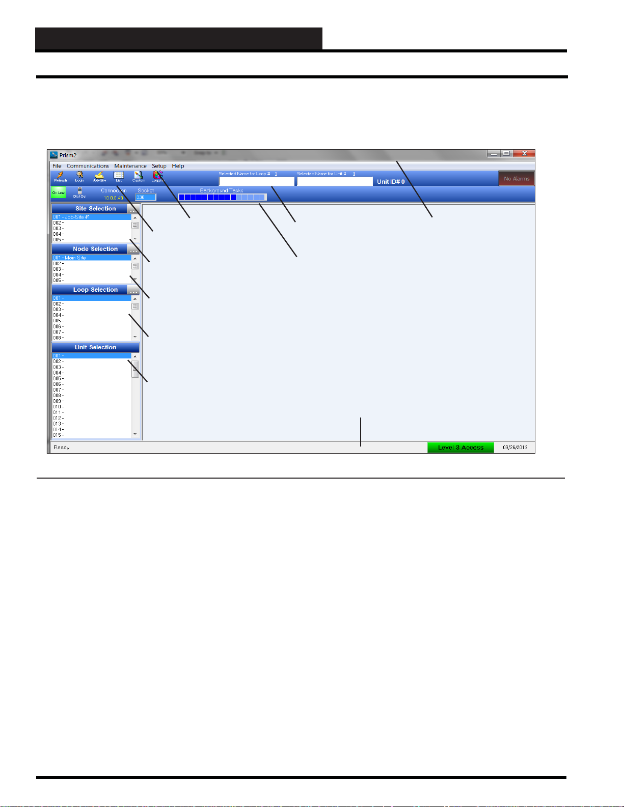
When you fi rst open Prism 2, the Prism 2 Main Screen appears.
(Figure 1)
Loop Selection
Window
Unit Selection
Window
Figure 1: Prism 2 Main Screen
Main Menu
Toolbar Icons
Site Selection
Window
Node Selection
Window
Top Toolbar
Lower Toolbar
Bottom Status Bar
Title Bar
The Main Menu contains the menus: File, Communications,
Maintenance, Setup, and Help.
The Top Toolbar displays the Refresh, Login, Job-Site, List,
Custom, Logging, and Weather buttons, Selected Loop Name,
Selected Unit, Unit ID #, and the Alarm button.
6
The Lower Toolbar displays the On-Line/Off-Line button, Dial-Out
button, Connection, and Socket.
The Bottom Status Bar displays the Program Status, Access
Level, and Current Date.
Located on the left side of the screen are the Site, Node, Loop and
Unit Selection Windows.
Prism 2 Technical Guide
Page 7
STEP 1: PRISM 2 INSTALLATION
Prism 2 Main Screen
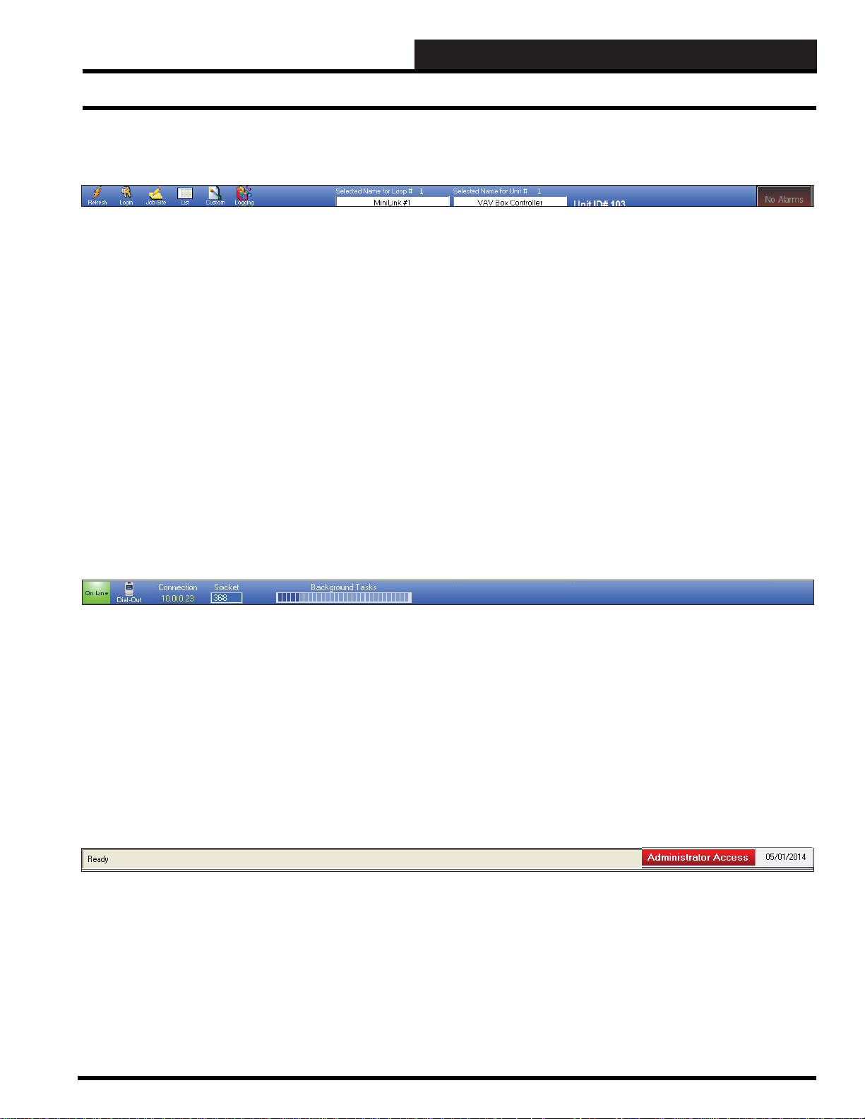
T op Toolbar
The Top Toolbar’s items are described below:
Refresh Button - Manually refreshes the screen. You may want to do this whenever you make a unit confi guration change.
Login Button - Opens the Enter Passcode Dialog Box, allowing each user to enter their user name and passcode and gain access
to the system.
Job-Site Selection and Setup Button - Opens the Job Sites Window where you enter job sites, nodes per location, serial port
or comm port #, IP address if applicable, and main screen display picture. You can enter 500 job sites, 500 nodes per job-site, 60
loops per node, and 60 units per loop.
List Button - Opens the List W indow where you can easily change names of loops and their units.
Custom Button - Opens the Custom Screen Graphics Program for you to create custom screens for your controllers. Can only
be accessed with a level 3 passcode.
Logging Button - Opens the T rend Logs Window where you can view, print, and graph system data.
Selected Loop - Indicates the Loop selected in the Loop Selection Window. You can also rename the loop here.
Selected Unit - Indicates the Unit selected in the Unit Selection Window. You can also rename the unit here.
Unit ID# - Indicates the numerical identifi er for the selected unit.
Alarm Button - Indicates an alarm(s) condition when bright red and displays <ALARM>. Will display <No Alarms> when none
are present.
Lower Toolbar
The Lower Toolbar’s items are described below:
Off Line/On Line Button - Displays whether or not the system has established communications.
Dial-Out Button - Used for remote connections to dial out.
Connection - Displays the IP address of the current job site. This only applies to TCP/IP connections.
Sock et - Used for factory level support diagnostics.
Background Tasks - When bars are full, indicates background communications are busy and may interfere with program
functionality.
Bottom Status Bar
The Bottom Status Bar’s items are described below:
.
Program Status Message - Indicates Ready or Not Ready for the CommPort connection. Will also communicate the status of
specifi c program tasks.
Access Level - This button displays the access level—View Status Only, Level 1, 2, 3, Factory Access, or Administrator
Access. If you click on this button while logged on, it will log you off and display View Status Only.
Current Date - Displays the current date.
Prism 2 Technical Guide
Revised 5/1/13
7
Page 8
STEP 1: PRISM 2 INSTALLATION
Entering Y our User Name & Pass word
Entering Y our User Name & Passw ord
NOTE: There are six pa sscode levels. Level 0, Level 1, Level
2, Level 3, Level 4—Factory Level Access, and Level 9—
Admin ist rator Acce ss. User name s and pas scodes ca n on ly be
set up and changed by the Administrator.
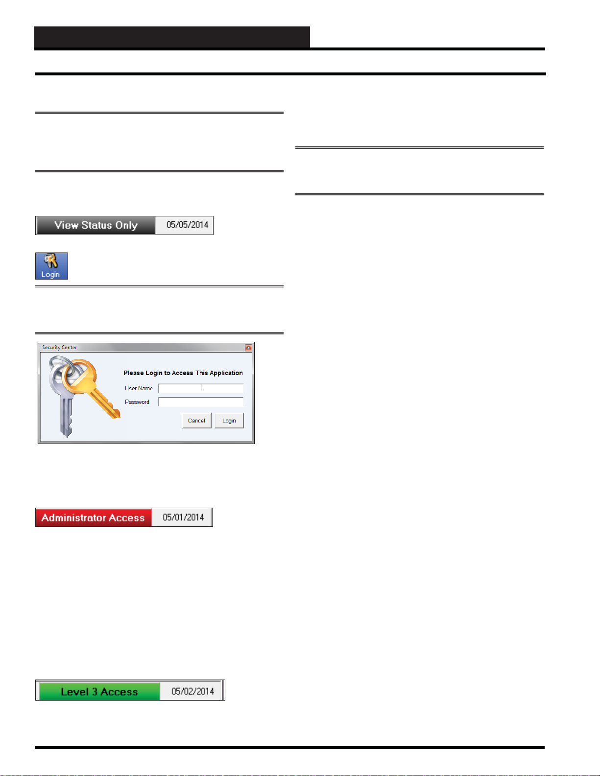
When you open Prism 2, the message View Status Only is
displayed on the right corner of the Bottom Status Bar.
Click the < Login> button found on the top left of the
Prism 2 Main Screen. The Login W indow will appear.
NOTE: Aside from when clicki ng the < Login> button, the
Login Window will automatically appear whenever Prism 2
needs a higher access level to perform a function.
Passcode Clearance Levels
Below is a list of the passcode levels and the default actions that
can be performed at the various levels.
NOTE: To increase or decrease t he default passcode levels for
changing Spa ce Temperat ure Setpoi nts and/or Schedules, see
Setup/ Confi guring Prism 2 on page 16.
Le v el 0—No P asscode Needed, View Status
Only, Logged Off
Level 0 users can view temperatures and other status but
no changes to setpoints, etc. can be made.
Le v el 1
Level 1 users can view temperatures and change space
temperature setpoints. The setpoint screens for Level 1
users are simplifi ed. No changes to schedules or other
settings can be made.
Le v el 2
Level 2 users can change space temperature setpoints and
operating schedules, but not confi guration settings.
System Administrators—Type in the Administrator User
Name and Password. By default, the User Name is admin and
the Password is admin. Then click <Login>. The status message
Administrator Access will now be displayed.
Once you have logged in as Administrator , you should now change
your Administrative User Name and Password. See Editing User
Names and Passwords on page 8. And also add User Names and
Passcodes for all users.
All Other Users—Once you have been given clearance, type in
your User Name and Password. Then click <Login>. The Login
Window will automatically close, and the passcode will be tested
against all previously defi ned passcodes to determine the passcode’s
access level.
The status message Level 1, Level 2, or Level 3 will now be
displayed.
Y ou can log off the system by clicking on the access level indicator
whenever you wish to secure the system.
Le v el 3
Level 3 users have system manager access and can change
all setpoints and confi gurations, but not user names and
passcodes. Level 3 users can also access force modes.
This Level is normally reserved for qualifi ed HVAC
service personnel.
Level 4— Factory Level Access
Factory Level Access allows additional troubleshooting
tools, confi gurations, and diagnostics. These items can
only be accessed under the direction of WattMaster
Controls T echnical Support.
Level 9—Administrator Access
Administrator Access is the only level that can Edit
User Names and Passcodes. The default User Name
is “admin” and the Password is “admin”. The defaults
should be changed and recorded by the Administrator.
If the Administrator for gets their login information, the
currently programmed Level 1 to Level 3 users will still
be able to access the system if they have been given
clearance. If not, Prism 2 will be locked out to all users
except for V iew Only Level. The Administrator will then
need to call WattMaster Technical Support for instructions
on how to restore operation.
8
Revised 5/1/13
Prism 2 Technical Guide
Page 9
STEP 1: PRISM 2 INSTALLATION
Editing User Names & Passcodes
Edit User Names & Passcodes
WARNING: MAKE SURE YOU CHANGE THE
ADMINISTRATOR USER NAME AND PASSWORD
IMMEDIATELY IN ORDER TO SECURE THE SYSTEM!
NOTE: Only the Administrator can edit User Names and
Pas swo rds . Y ou MUST press <ENTER> in each fi eld to have
the system accept the information.
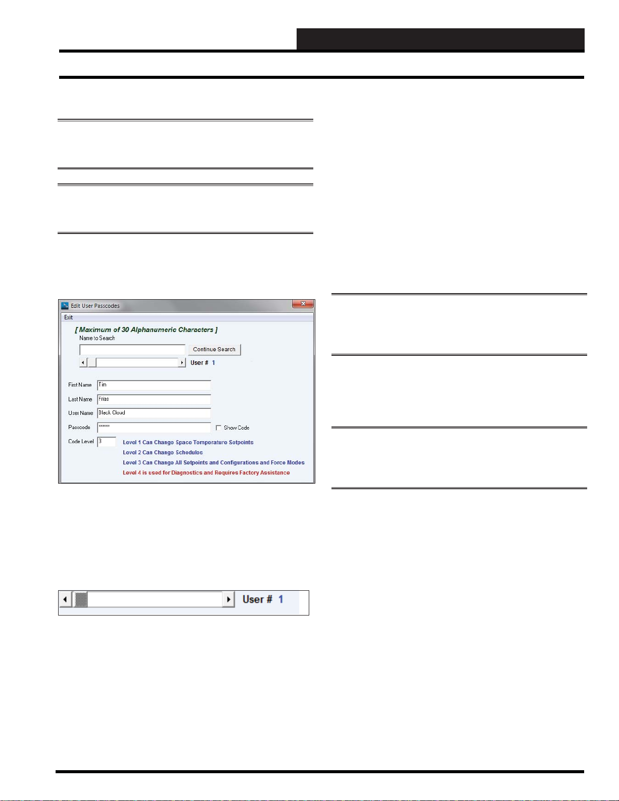
From the Prism 2 Main Menu, click < Edit Passcodes> from the
File Menu. The Edit User Passcodes Window will appear. See
below for an example of setting up information for a Level 3 User.
Step 3: T ype the last name of the User in the Last Name fi eld
and press
<ENTER>. In this example, the name is Frias. You can
enter up to 30 alphanumeric characters. The Last Name is used by
the History Log to identify who logged into the system and any
setpoint changes they may have made.
Step 4: Type the user name of the User in the User Name fi eld
and press <ENTER>. The User Name could be a nickname or a
shortened version of the person’s name. You can enter up to 30
alphanumeric characters. In this example, the User Name is Black
Cloud.
Step 5: Type a password in the Passcode fi eld and press <ENTER>.
Click the Show Code check box if you wish to see the characters
while you are typing. You can enter up to 30 alphanumeric
characters.
NOTE: A strong password is defi ned as at least 14
characters long and containing characters from at least 3 of
the following 4 classes: upper case letters, lower case letters,
numbers, and special characters, except for an apostrophe ‘.
Step 6: Type the passcode level of the User in the Code Level
fi eld. Valid entries are 0, 1, 2, 3, 4, and 9. Press <ENTER>. Refer
to defi nitions of Passcode Clearance Levels on page 8 for further
details.
Step 1:
Identify the User Number by using the scroll bar. Or, if
you already have the Users setup and are editing, you can type
their name in the Search Field. If changing your Administrator
User Name or Passcode, it will appear in the window ahead
of User #1. Click the right arrow in the scroll bar and the user
number will change sequentially. In the example above, you are
setting up the information for User # 1.
You can enter 100 different users. This may increase in future
versions.
Step 2: Type the fi rst name of the User in the First Name fi eld
and press <ENTER>. In this example, the name is Tim. You can
enter up to 30 alphanumeric characters. The First Name is used by
the History Log to identify who logged into the system and any
setpoint changes they may have made.
NOTE: Only the Administrator can be set for Level 9.
The maximum level for a normal user is 4, but that level
should only be reserved for maintenance personnel and
not used by anyone else.
Step 7: When you are fi nished editing, click <Exit> to close the
window.
Prism 2 Technical Guide
Revised 5/1/13
9
Page 10
STEP 2: JOB-SITE SET-UP
Job-Site Set-Up
Step 2: Setting Up Job Sites
The second step in the Prism 2 Setup procedure is to program the
specifi c job-site access settings and desired initial displays for each
location.
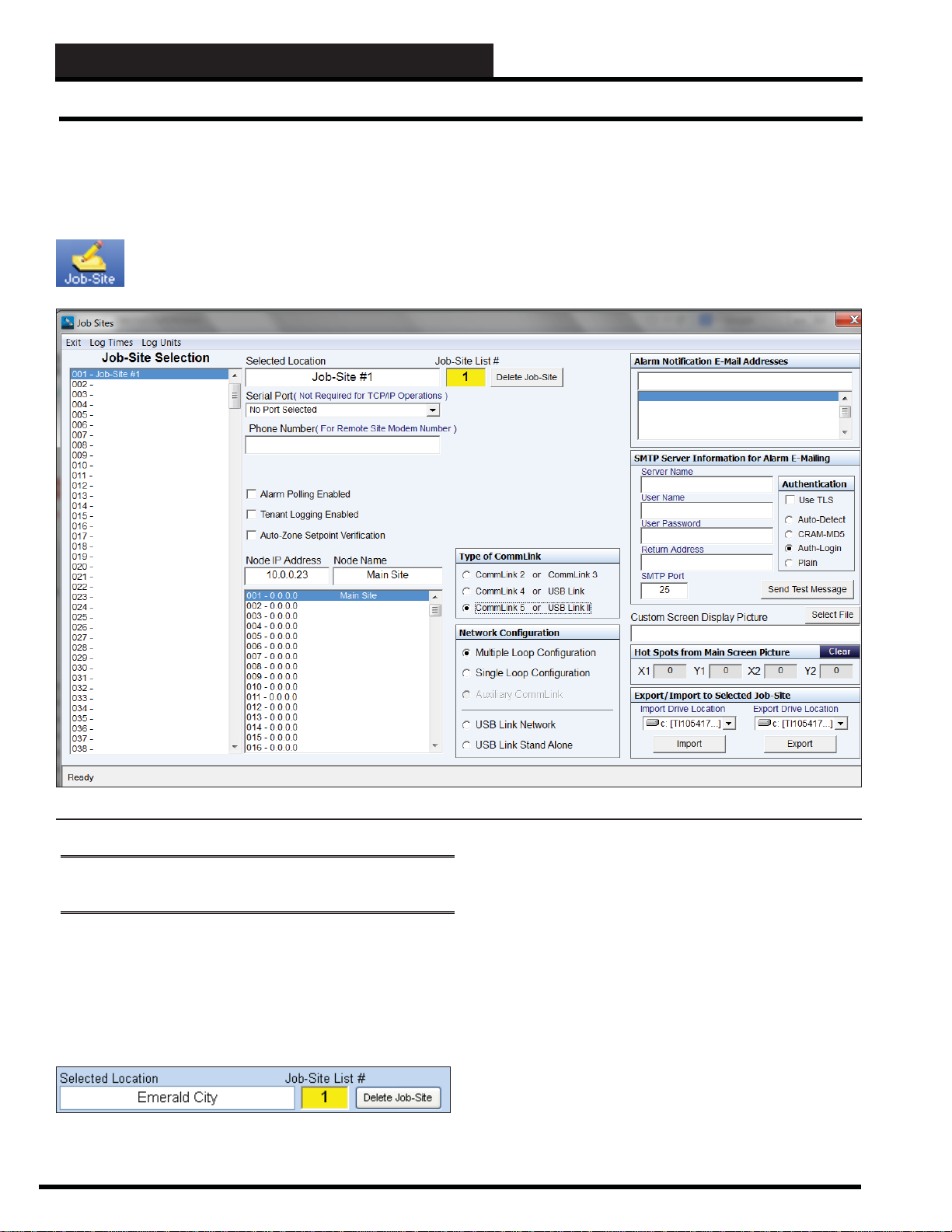
Click on the < Job-Site> button located on the Top
Toolbar of the Prism 2 Main Screen. The Job Sites
Window will appear. (Figure 2)
Figure 2: Job-Sites Window
NOTE: You must confi gure each of the fi elds in this window for
every one of your job sites.
Job-Site Name:
When you fi rst open the Job Sites Window, the Job-Site Selection
Window will be empty. Click on an empty location. The Job-Site
List # will display the number you have selected. In the Selected
Location fi eld, type a name for your job-site and press <ENTER>.
10
Revised 9/25/13
Serial Port:
TCP/IP—If you are using TCP/IP communications, leave the
Serial Port field set at “No Port Selected” which is the default.
Serial or USB—If Prism 2 will be connecting directly to a
CommLink through the Serial or USB Port, select the port that you
have connected your CommLink to and enter 0.0.0.0 for the Node
IP Addr ess. COM Port #9 is the maximum port number supported
by Prism, so if your USB port is #10 or higher, you will need to
manually force the port to a lower port number using the Device
Manager found in your Windows® Control Panel. This procedure
is documented in WattMaster’s CommLink IV and CommLink 5
T echnical Guides.
Prism 2 Technical Guide
Page 11
STEP 2: JOB-SITE SET-UP
Job-Site Setup
Phone Number
If you are confi guring Prism 2 to access to a remote job-site that
uses a modem connection instead of an Internet connection, enter
the modem phone number in this box. It may be necessary to put
a pause in with a comma to successfully dial out. Prism 2 will dial
this number to make a connection when you select this job-site and
< Dial-Out> button.
the
Alarm Polling Enabled
If you require a time and date stamped log of alarming or you
require e-mail notifi cation of alarms, check this box to enable
Prism 2 to poll for alarms. Checking this option will cause the
Alarm button to light up on the Prism 2 Main Screen. Prism 2 must
be left running on a computer 24 hours a day, 7 days a week for this
function to operate correctly.
Tenant Logging Enabled
If you are not using an Internet connection, enter 0.0.0.0 in this
fi eld and press
<ENTER>. If using TCP/IP, enter the IP address of
your CommLink IV w/IP or CommLink 5 w/IP device and press
<ENTER>.
NOTE: If you are using a crossover cable to connect your
CommLink IV w/IP or CommLink 5 w/IP to your computer,
you will need to access your Network Settings in your Windows
®
Control Panel, change from DHCP to a Static IP Address, and
enter the IP Address and Mask provided by your IT personnel.
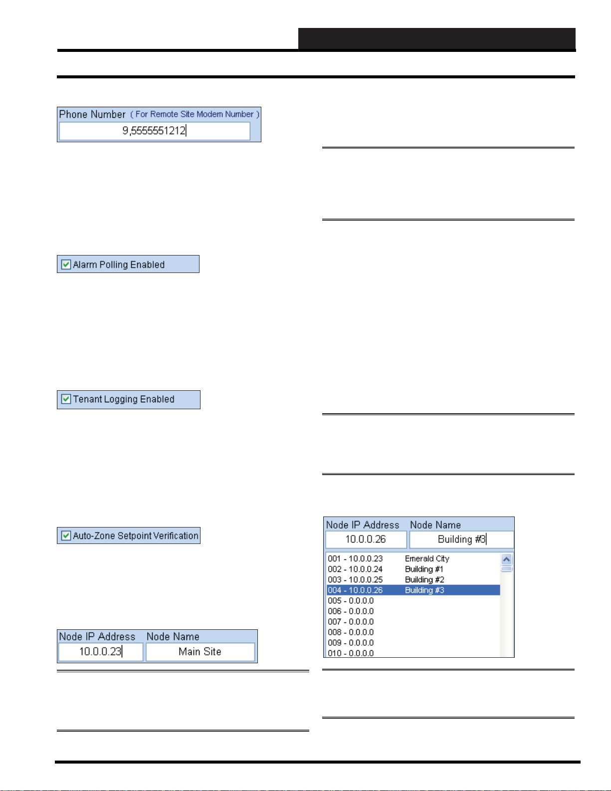
The Node IP Address identifi es the TCP/IP address of the
CommLink IV w/IP or CommLink 5 w/IP that you will be accessing
for the selected job-site. If your job-site has multiple buildings with
multiple CommLink IV w/IP or CommLink 5 w/IP devices, each
device address can be programmed here.
Simply select the location from the list box to program and type in
the IP address in the xxx.xxx.xxx.xxx format. You can also enter a
name for each Node or CommLink IV w/IP or CommLink 5 w/IP
to aid in identifying which building you are communicating with.
This allows multiple CommLinks to appear as one job-site, and
Prism 2 will then be able to monitor all nodes for alarming or trend
information instead of a single node. You can enter up to 500 nodes
per job-site.
If you require tenant unoccupied override information for billing
purposes and have installed the MiniLink Polling Device, check
this box. Prism 2 can be confi gured to monitor for individual tenant
space temperature sensor push-button overrides and can create
reports totalizing each zone’s after- hours usage. See Section 11 T enant Override Logging for more information.
Auto-Zone Setpoint Verifi cation
Only check this box if you are using Auto-Zone Controllers. Do not
check this box if you are not using Auto-Zone Controllers, because
it will slow communications.
Node IP Address and Node Name
NOTE: Only CommLink IV w/IP or CommLink 5 w/IP
devices can be con fi gured and used a s mu ltiple Node device s.
Serial versions a nd older versions of the Com mLink a re not
supported.
NOTE: Please avoid skipping Node addresse s in the l ist box
and keep all your CommLinks consecutively listed. 001 is
always the Main Job-Site. The 001 Node Name defaults to Main
Site, but you can change the name.
The fi gure below shows an example of Node IP Addresses and
Node Names for a job-site with multiple buildings.
NOTE: You should never have a Serial Port and a Node
IP address entered at the same time. Only one method of
communications is available per job-site.
Prism 2 Technical Guide
Revised 7/25/11
11
Page 12
STEP 2: JOB-SITE SET-UP
Network Configuration and Alarm Notification
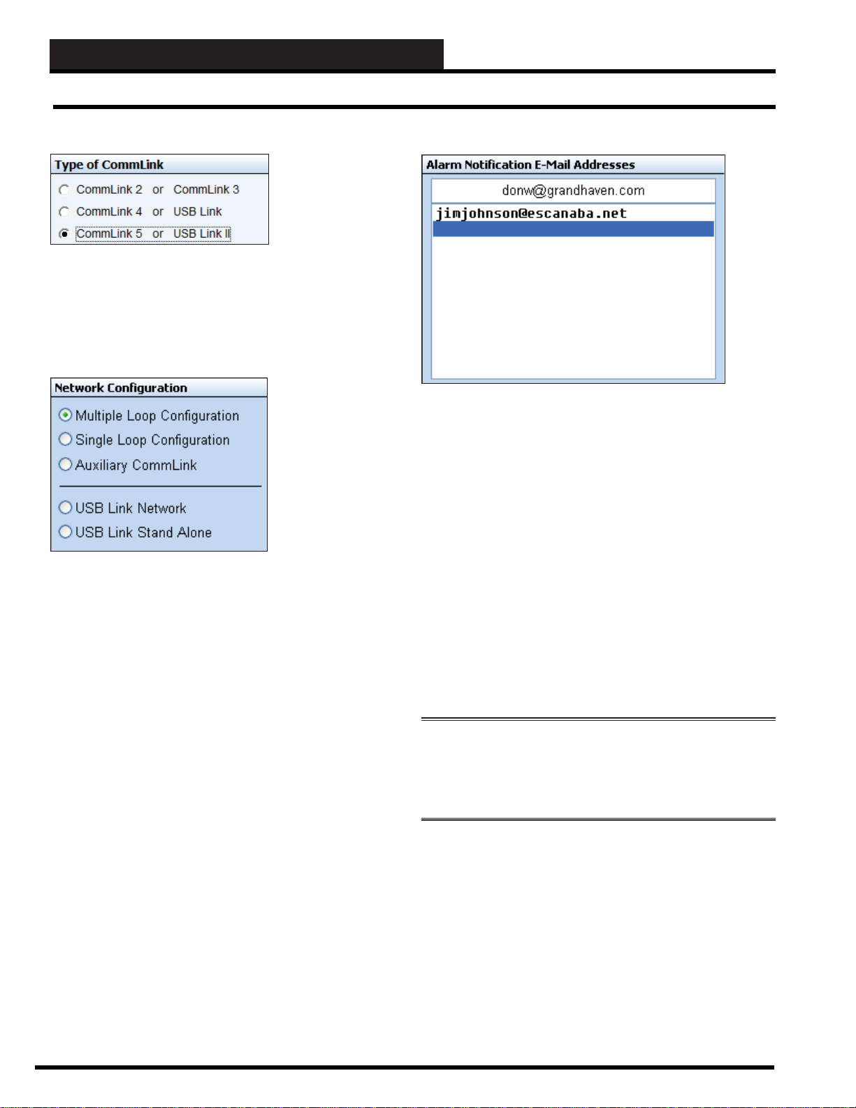
Type of CommLink
In the Type of CommLink Selection Box, select the type of
CommLink or USB-Link that you are using. If you are setting up a
node, the only type of CommLink you can use is a CommLink IV
w/IP or CommLink 5 w/IP.
Network Confi guration
You must select the confi guration of the CommLink or USB-Link
you have connected to your computer as this affects setting up the
CommLink and polling for alarms.
Multiple Loop System contains MiniLinks that divide up
Confi guration the units across logical boundaries or contains
large quantities of similar units that exceed
the number of units allowed on a Single
version CommLink. CommLink must be set
to Multi.
Single Loop System contains 60 or fewer units that can
Confi guration exist on a single communications loop.
CommLink must be set to Single.
Auxiliary This is only applicable on older existing
CommLink systems. System contains a CommLink set
to Multi and MiniLinks and the user needs to
add a second computer to monitor the system.
The second computer cannot be used for
alarm monitoring.
USB Link System contains a standard CommLink.
Network USB-Link must be set to Network.
USB Link System does not have a CommLink or
Stand-Alone you are connected to a single controller and
have disconnected the communication loop
from the board. Set the USB-Link to Stand
Alone.
Alarm E-Mail / Text Message Notifi cation
If you require e-mail or text message alarm notifi cation, you may
enter up to 10 e-mail addresses in this list box. Prism 2 must be
enabled for Alarm Polling and must be running continuously to
monitor for new alarms and generate e-mails containing the alarm
information. See how to set up text messaging in the T ext Message
section below.
T ype an e-mail address and press
<ENTER>. The e-mail address
will appear in the box below the entry fi eld. Click on an empty line
below the e-mail address you just typed and then place your cursor
back in the fi eld to type an additional e-mail address. To delete
an e-mail address, click on it so that it appears in the entry fi eld,
highlight it, and press the <BACKSPACE> key or <SPACEBAR>
and then press <ENTER>.
Whenever an alarm is detected, each individual on the list will
receive e-mail or text message notifi cation of the site location, the
unit address and description, and a brief text message identifying
the alarm condition.
WARNING: Your computer must be set up with a standard
e-mail account using any of the standard e-mail programs such
as Outlook Expres s or Mozilla Thu nderbird for this opt ion to
operate correctly! Failure to set up a standard e-mail account will
result in unreliable alarm notifi cations!
Te xt Message— Most cell phone providers have as a free* option
(charges may apply in some instances) an E-mail to TEXT service
for their cell phone plans. Any alarm type level that is generated
would be sent to that cell phone number as a text message. *Usually
the cell phone providers will have an unlimited text messaging
option.
When using Verizon cellular service, the text messaging e-mail
address is your 10-digit phone number followed by @VTEXT.
com. For example, if your phone number is 1-555-555-5555, your
e-mail address (for TEXT MESSAGING) would be 5555555555@
VTEXT .com.
12
Revised 9/27/13
Prism 2 Technical Guide
Page 13
STEP 2: JOB-SITE SET-UP
Alarm E-mailing and Display Picture
When using Sprint cellular service, the text messaging e-mail
address is your 10-digit phone number followed by @messaging.
sprintpcs.com. For example, if your phone number is 1-555-5555555, your e-mail address (for TEXT MESSAGING) would be
5555555555@messaging.sprintpcs.com.
When using AT&T cellular service, the text messaging e-mail
address is your 10-digit phone number followed by @txt.att.net.
For example, if your phone number is 1-555-555- 5555, your e-mail
address (for TEXT MESSAGING) would be 5555555555@txt.att.
net.
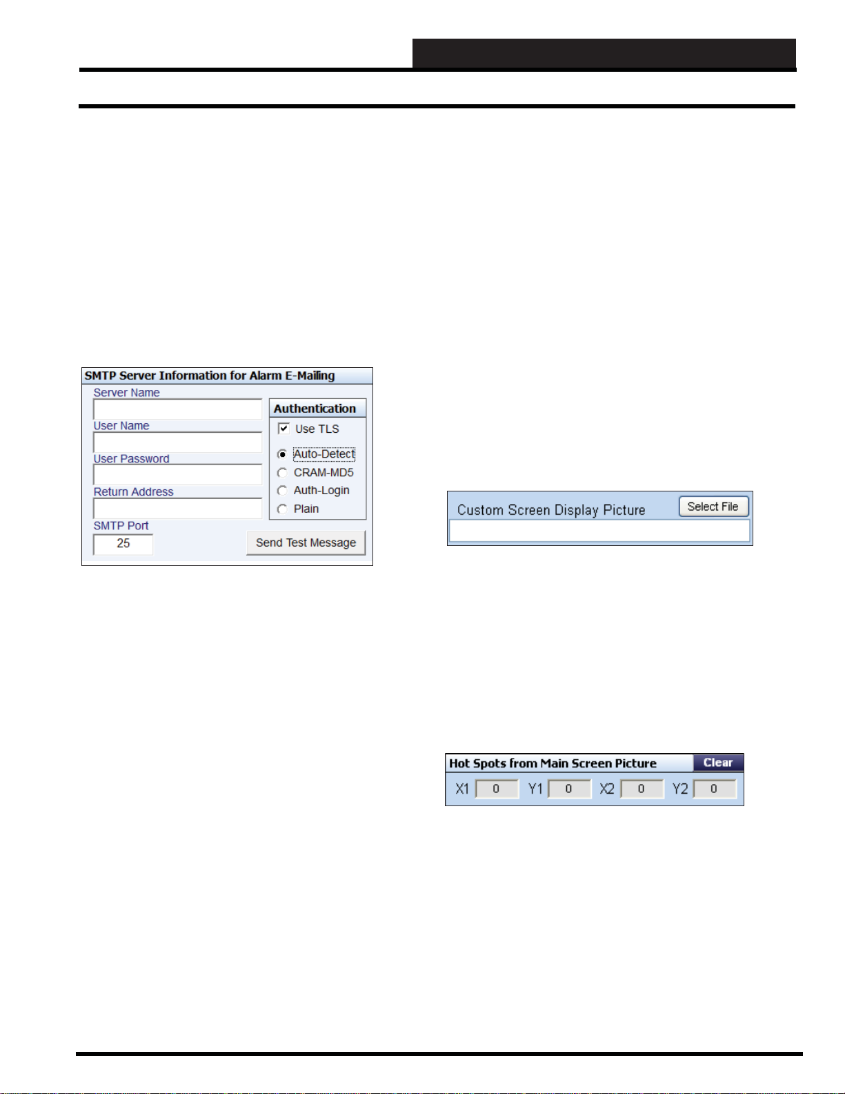
SMPT Server Inf ormation for Alarm E-Mailing
Auto-Detect:
If you don’t know which method your server uses, you can select
this option and the MailSend program will try each method and use
the one that operates on your system.
CRAM MD5:
This would be the default method if TLS is checked. It is not
available if TLS is not checked, but the other 3 methods are. Your
service provider can tell you if this is the preferred method.
Auth Login:
Your service provider will tell you if this is the required method to
send authenticated e-mail.
Plain:
No authentication is required to send e-mail.
Send Test Message:
Click this button to send an alarm notifi cation test message to
everyone listed in the Alarm E-Mail Notifi cation Dialog Box.
Custom Screen Display Picture
Server Name:
This is the SMTP mail server provided when you set up your e-mail
account. For example, Time W arner Cable uses smtp-server.kc.rr.
com and WattMaster uses mail.wattmaster.com
User Name:
This is the e-mail address you created when you set up your e-mail
account.
User Password:
This is the password required to send and receive mail on your
account.
Return Address:
This is the address that is notifi ed when the mail is undeliverable.
SMTP Port:
Use the default port #25 unless your IT department specifi es
otherwise.
In the Authentication Window:
Use TLS:
This should be checked unless your e-mail service does not require
secure e-mail transactions.
Once you have created your Custom Screen(s) you can revisit this
fi eld. Custom Screen instructions are found on page 33. Custom
Screens can be fl oor plans or groups of controllers or whatever you
decide is necessary to ease the monitoring of your system. When
you revisit this fi eld, click the <Select File> button to select the
custom screen you wish to be associated with the job-site. Once
you choose a Hot Spot from the Main Screen display (described
on page 38), you can click on the Hot Spot and go straight to the
custom screen.
Hot Spots from Main Screen Picture
Once you create a Hot Spot on the Main Screen display (described
on page 38), the coordinates for the Hot Spot will show up in this
fi eld. If you have forgotten where you placed a Hot Spot, these
coordinates will allow you to troubleshoot the location. If you want
to delete a Hot Spot, click the <Clear> button.
Prism 2 Technical Guide
13
Page 14
STEP 2: JOB-SITE SET-UP
Auto-Logging
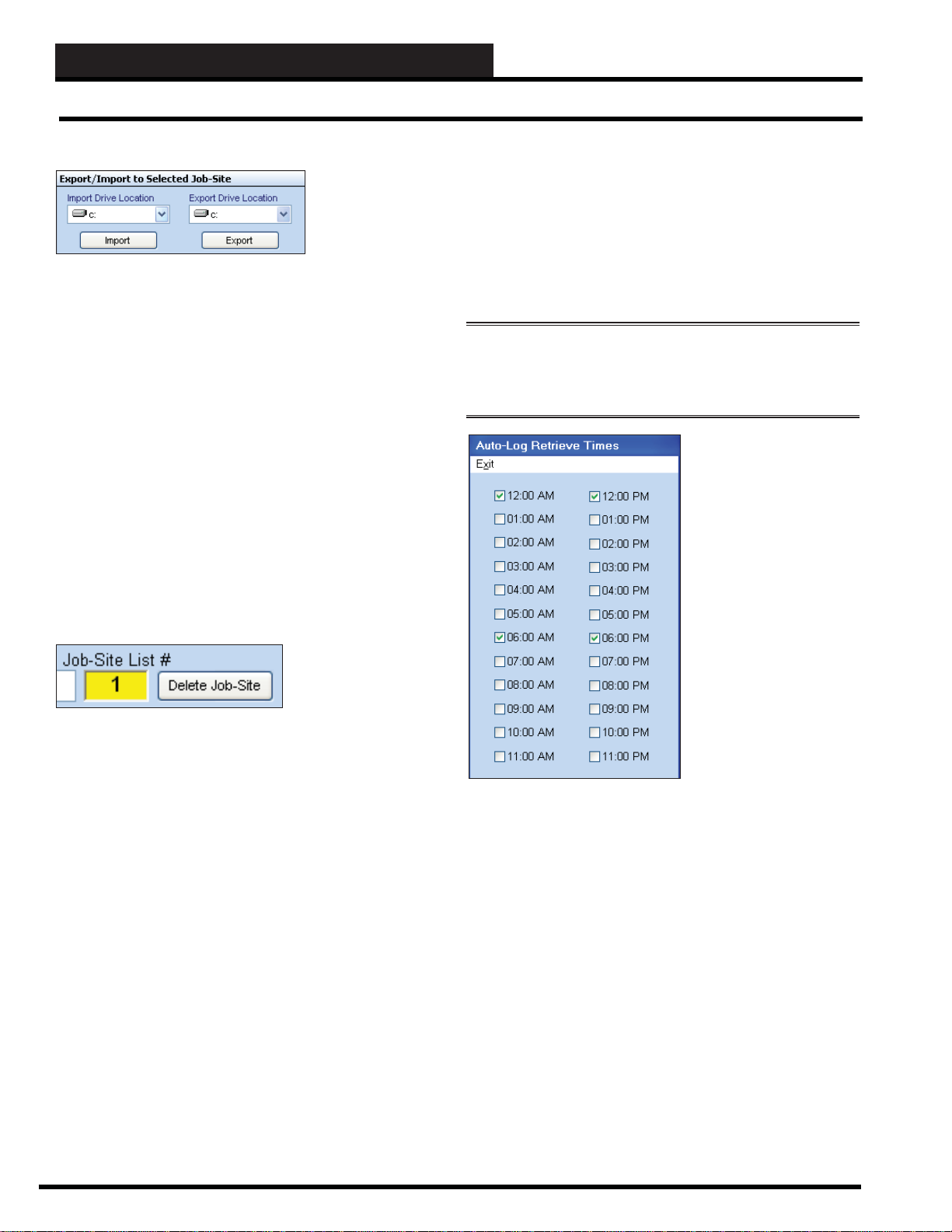
Export/Import to Selected Job-Site
Once you have completed setting up your job-site and have
performed a search for all installed units (see page 20) and have
given them names, you can revisit this fi eld which enables you to
copy job-site settings to another computer so you don’t have to reenter the information.
T o export data, select the job-site you wish to export by highlighting
it and then select the Export Drive Location to store this information.
Y ou can export to any form of removable media that your computer
is capable of writing to. Make sure that the media you choose is
supported by the computer you will be importing this data to! Click
<Export> button to initiate this procedure. Once the data is
the
stored, take the removable media to the other computer, insert it,
and select the Import Drive Location for that computer and the job
site list number (click in the Job-Site Selection List Box to make
this selection) and then click the <Import> button. All installed
units and names should now appear on the Prism 2 Main Screen
when you exit the Job Sites Window.
Delete Job-Site
Auto-Logging Settings
Log Times
If you would like Prism 2 to automatically retrieve controller
trendlogs on a regular basis, click
Window’s Top Menu Bar. The Auto-Log Retrieve Times Window
will appear. Select the times of the day you would like Prism 2 to
perform this function.
NOTE: You can force Prism 2 to start the Auto Logging
procedure at any time by making sure your communications are
On Line an d th en selecting < Start AutoLog> from P ris m 2 ’s
Communications Menu.
<Log Times> from the Job Site
How often you should
gather logs depends on the
shortest logging interval
you have specifi ed on any
selected controller. Some
of the older families of
controllers support 60
rows of log data whereas
newer families have 120
rows. Each row of log data
contains a time and date
stamp and any relevant
data for the type of control
it performs.
If you want to delete a job-site, highlight the job-site in the Job-
Site Selection Window so that its name appears in the Selected
Location fi eld. Then click the <Delete Job-Site> button next to
the Job-Site List # fi eld.
A message will appear asking you if you really want to delete the
job-site. This is a precaution in case you click the <Delete Job-
Site> button by mistake. Click <Y es> or <No>.
For example, a Variable
Air Volume Box Controller
logs its Space T emperature,
Heating and Cooling
Setpoints, Supply Air, and
Damper Position in each
row.
If you entered the shortest log interval of 1 minute for a unit with 60
rows of data, you would need to retrieve data every hour to prevent
loss of log data. If you left the default log interval of 15 minutes,
then you could load the log data twice a day and not lose any data
since 15 minutes times 60 rows = 900 minutes of data (15 hours).
On a unit with 120 rows, that same 15-minute interval would yield
1800 minutes of data or 30 hours, which means you could retrieve
logs once a day without losing data. Don’t worry about overlapping
data if your logs exceed the auto-log interval. All duplicate data
is discarded and any fi les created for a single day are loaded as a
whole to create one log listing per day. Keep in mind that a time
and date stamped fi le is created every time you retrieve a log from
a controller, so unnecessary polling should be kept to a minimum.
If you retrieve logs every hour, then 24 fi les will be created for each
day of the year.
14
Prism 2 Technical Guide
Page 15

Log Units
Once you have selected the Log Times, you need to select which
units to retrieve log data from. If you have controllers such as
Lighting Panels which don’t have internal logs, you don’t need to
select them. Also, if you don’ t need archival storage of log data, you
may only want to activate this feature to troubleshoot a job-site, and
then disable this feature once everything is running smoothly again.
<Log Units> from the Job Site Window’s Top Menu Bar and
Click
select units to be logged.
STEP 2: JOB-SITE SET-UP
Auto-Logging
As you can see on this sample screen, only three units have been
selected for auto-logging four times a day (See Log Times sample
screen). All other units will be ignored during this process.
Keep in mind that on systems with multiple communications loops,
you will need to select each loop one at a time from the Loop
Selection List Box and then check each desired unit on the selected
loop.
NOTE: If you are using multiple CommLink IV w/IP or
CommLink 5 w/IP devices on a ca mpus setting, you will ne ed
to sel ect eac h N od e an d th en ea ch Loop al on g with the U nits on
those loops that you would like to auto -log. Prism 2 will op en
communicatio ns wi th eac h Co mmLink IV w/IP or CommLink
5 w/IP in order and retrieve the logs from each building.
NOTE: Auto-logging places a heavy demand on the
communications pipeline. If you are viewing Status or Setpoint
screens when it is time for an auto-log to occur, it would be best to
close out your viewing session until the logging is complete. This
helps to avoid missing packets of data or extending the logging
procedure be cause it would be competi ng for commu nicat ions
time with a Status Screen polling for live data.
Prism 2 Technical Guide
15
Page 16
STEP 3: PRISM 2 CONFIGURATION
Configuring Prism 2
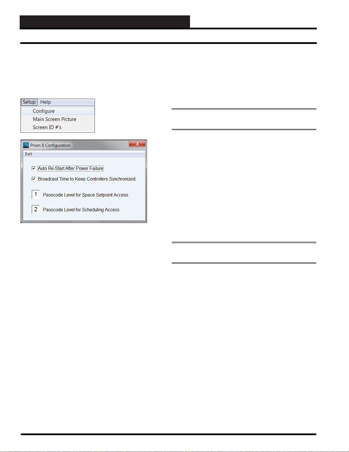
Step 3: Configuring Prism 2
Prism 2 can be confi gured to poll for trendlogs or alarm conditions
on a continuous basis. If your computer experiences a power
outage, Prism 2 will not automatically restart without a few user
settings to make this happen.
From the Setup Menu, click
< Confi gure>.
The Prism 2 Confi guration
Dialog Box will appear.
Broadcast Time to Keep Controllers
Synchronized
Select this option to keep all controller real time clocks synchronized
and to handle daylight savings changes.
Click the checkbox for Broadcast Time to Keep Controllers
Synchronized.
NOTE: Prism 2 must be r u nn ing on a c ontinu al basis for th is
option to work.
This broadcast occurs once an hour and is helpful in keeping all
time stamped items, such as trendlogs, synchronized with each
other.
Passcode Level for Space Setpoint Access and
Scheduling Access
Although passcode level access defaults are set in the Edit
Passcodes Window (see page 9), you can increase or decrease
the default passcode level access for Changing Space Setpoints
(default Level 1) and for changing Schedules (default Level 2) to
levels between 0 through 3.
Auto Re-Start After Power Failure
Click the checkbox for Auto Re-Start After Power Failur e.
In order for Prism 2 to automatically restart after a power failure,
you must place a shortcut to PrismII.exe into the C:\Documents
and Settings\All Users\Start Menu\Programs\Startup folder.
When the computer reboots and Prism 2 restarts, the
communications port will open up automatically and resume any
alarm or trend logging.
An Uninterruptible Power Supply ( UPS) device can be attached to
your computer to handle the short power glitches and prevent the
computer from needing to re-start. Longer power outages will still
need this auto re-start method to return to normal operation.
In order for Prism 2 to save any changes that you make in these
fi elds, you must press <ENTER> after entering the new value.
NOTE: You must have a Passcode Level of 3 or abov e to change
these settin gs.
16
Revised 9/25/13
Prism 2 Technical Guide
Page 17

STEP 3: PRISM 2 CONFIGURATION
Main Screen Display Picture
You can substitute Prism 2’s Main Screen WattMaster Controls
logo display with a bitmap ( BMP, JPEG, or GIF format) of your
choice.
From the Setup Menu, click < Main
Screen Picture>.
The Main Screen Picture Dialog Box
will appear.
Configuring Prism 2
Click the <Select Picture> button to select your desired image.
The File Open Window will pop up:
Search for the image until it appears in the Selected Dir ectory
fi eld. Click the fi lename once so that it appears in the Selected
File fi eld and then click the <Open> button on the File Menu Bar.
The fi le you choose should immediately appear in the Main Screen
display.
Prism 2 Technical Guide
17
Page 18

STEP 4: SETTING UP COMMUNICATIONS
TCP/IP Connection and CommLink Setup
Step 4: Setting Up Communications
This section discusses the initial settings required to get Prism
2 communicating with your WattMaster digital controls. Your
CommLink communications device must already be installed and
all communications wiring must be completed before Prism 2 can
communicate with your system.
Once the job-site has been confi gured, you should be able
to initiate communications with the attached CommLink
device. Click on the < Off Line> button to force Prism 2 to
open a communications port or socket to the CommLink.
If it is successful, the button indicator will light up and
display < On Line>.
Each time you click this button, Prism 2 will either open
communications and display <On Line> or close communications
and display <Off Line>.
NOTE: If you are u sing a USB-Link or auxi l iary CommLink,
you can skip the rest of this section and go directly to “Searching
For Units” on page 20.
TCP/IP Connection
The Dialing Status and Connection Window will appear and the
<Dial Out> button will display < Cancel Dialout>. Verify that you
are dialing the correct job-site.
Click the <Cancel> button if you need to terminate the dialing
sequence before it has fi nished.
The Dialing Status and Connection Window will provide all of the
information you need to determine the dialing state and its success
or failure. Once the Connection Status indicates a successful
connection, simply click <OK> to close the window and begin
normal communications with the remote job-site.
When you are done completing the tasks for the job-site
you dialed, click the < Hang Up> button. This button
replaces the <Cancel Dialout> button once a modem
connection is successful.
CommLink Setup (For Remote Connection Only)
If you are using a CommLink
IV w/IP or CommLink 5 w/
IP device, you need to set up
initial settings by clicking
< CommLink IP Web Settings>
from the Communications
Menu. In the menu at left,
this item is grayed out, but
when you actually plug in
your CommLink IV w/IP or
CommLink 5 w/IP device, this
menu item will be accessible.
A separate document is provided
with the CommLink IV w/IP or
CommLink 5 w/IP device which details all required settings and
confi gurations and will not be discussed in this manual.
The initial setup is performed with your installed web browser. This
option is provided in Prism 2 to eliminate the need to run a separate
program to verify settings while troubleshooting or performing
other changes as specifi ed by WattMaster Technical Support.
Modem Connection
If Prism 2 is able to open
communications, you can now
confi gure the CommLink with
the proper settings. From
the Communications Menu,
click < Setup CommLink>. The
CommLink Settings Window will
appear.
Verify the Type of CommLink
- Multiple Loop, Single Loop,
Auxiliary, USB Link Networked,
and USB Link Stand Alone. This
selection should default to what
you set up for the job-site in the Job
Sites Window.
Click < Load> to retrieve the current settings from the CommLink
device.
18
If you are connecting to a remote job-site via a modem
connection, you must select the < Dial-Out> button
located next to the < On Line/Off Line> button.
Prism 2 Technical Guide
Page 19

STEP 4: SETTING UP COMMUNICATIONS
CommLink Setup
CommLink ID Number
A two-digit number used to identify which remote location has
been contacted. Any valid number from 00 to 99 will work.
Version
This is a default setting that is read from the CommLink.
Baud Rate
The Baud Rate only applies to the modem connected to the
CommLink for remote access.
Phone Number
Not currently required or used by the Prism 2 program. You should
leave this fi eld blank (displays “None” if blank). If this fi eld is not
blank, simply highlight the current data, press <BACKSPACE>
and then press <ENTER>. This will clear the data.
Alarm Callout Cell / Pager Number
You can enter a pager number or cell phone number in this fi eld if
you want someone to be paged or called whenever an alarm occurs.
The maximum number of characters available for this fi eld is 28.
Press the <Space Bar> to clear this fi eld.
Cell Phone—If you are typing in a cell phone number, type it in
the way suggested by your phone service provider.
NOTE: In your cell phone entries, you will need to create an
entr y for each of your job sites with its cor respondi ng phone
number so that you know which job site has an alarm.
Pager—Enter a pager number if you want someone to be paged
whenever an alarm occurs. After the pager number , type 4 commas
and then enter the number the modem is calling from followed by
the # sign so the person knows whom to call back.
Modem Init String
The settings provided are for the WattMaster Remote Link
modem. No other modems may be used. The maximum number of
characters available for this fi eld is 28.
ATS0=1S7=120&C1&D2X1%E0&W0
You do not need to remember this string, simply click < Restore>,
and the fi eld will be fi lled in for you.
NOTE: T he nu mb er one cau se of failu r e for a remote mo dem
that does not answer a call from Prism 2 is the SO=1 command
is actually set to SO=0. If it is ZERO the Modem WILL NOT
ANS WE R!
Saving the CommLink Settings
When you are satisfi ed with the CommLink settings, you must
click <Save> to force Prism 2 to send the new settings back to the
CommLink.
It is always a good idea to select <Load> after you Save the data
to verify that the correct data has been stored in the CommLink
memory.
Click <Exit> to exit the CommLink Settings Window.
At this point, it is a good idea to cycle power to the CommLink so
that the new settings will have a chance to take effect.
NOTE: Because there are thousands of different modems
available on the market, WattMaster Controls can only
support the Remote Link modem that has been designed
specifi cally for this system.
Example: 555 1212,,,,555 1234#
555 1212 The Pager Number to Dial
,,,, Commas Command the Modem
to Pause
555 1234 The Number of the Modem
making the call.
# Closes out the Pager Notifi cation Sequence
Prism 2 Technical Guide
Revised 7/25/11
19
Page 20
STEP 5: SEARCHING FOR INSTALLED UNITS
Unit Search
Step 5: Searching For Installed Units
Once all controls are up and running and all communications have
been set up and tested, you need to search for installed units on the
communications loop.
Make sure Prism 2 is On Line and you have Level 3 access. If
you are using a Remote Link, you will need to dial out to make
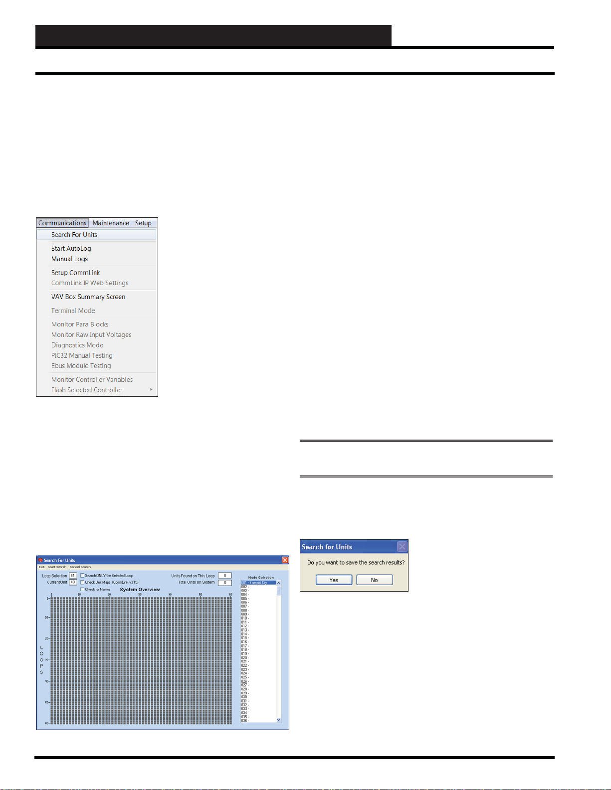
a connection. From the Main Menu, click <Communications>,
< Search For Units>.
Each gray box symbolizes a board address from one to sixty on a
maximum of 60 loops. As each unit is checked for on a loop, the
gray box will turn yellow. If a unit is found, the box will turn green.
If no unit exists at a specifi c address, the box will turn red.
If you are testing a specifi c address during installation or
troubleshooting to see if it is recognized, fi nd the correct box using
the left mouse button. The selected loop and unit addresses will
appear in the upper left corner in the Loop Selection and Current
Unit fi elds. To actually test that unit, use the right mouse button.
If the unit is found, the box will turn green; otherwise it will turn
red.
Once all addresses are checked, the total number of units or
controllers found for each loop will be displayed at the top of the
screen.
If the number per loop matches the actual number of installed
HVAC controllers, click
If you think you have consecutively addressed all of your
controllers but you see a green box located apart from the group,
you can assume you have improperly set the address switch for
that controller. However, in some cases, such as AHU Units and
MiniLink Polling Devices, they will be located at the end of the
loop at addresses 59 & 60 and no corrections are necessary .
<Exit> and save your search results.
The Search For Units Screen will appear.
If you are using a USB-Link, you should select the Check Unit
Maps option or the search will not reliably detect installed units.
To search a single loop, click on any box on the desired loop, and
select the Search ONLY the Select Loop checkbox. Other loops
will be ignored, but units previously found on other loops will not
be discarded.
Click < Start Search>.The search process will automatically look
at all 60 possible addresses on each loop unless you click < Cancel
Search> to stop the process.
If the number does not match, you will need to diagnose the
communications problem and perform searches until the number
of detected units matches the number of installed units.
NOTE: You can select <Cancel Search> at any time if you
know there are no more units to be found on your system.
Click <Exit> when you are fi nished with your search or wish to
close the Search For Units Scr een. The following message will pop
up, asking if you want to save your search results:
Click <Yes> if the detected number matches the actual number of
installed units and you wish to save the search results. If you select
<Y es>, the new search fi le will overwrite any previously saved
search fi le.
Click <No> if the numbers don’t match or you are troubleshooting
the system and don’t want to save the results. If the numbers
don’t match, make sure your system is On Line and check other
communication confi gurations as necessary .
20
No matter which search method is used, you can always choose to
save or discard the search results when you exit this screen.
Prism 2 Technical Guide
Page 21

STEP 6: SELECTING & RENAMING UNITS
Selecting and Renaming Loops and Units
Step 6: Selecting and Renaming
Loops and Units
This section explains how to select and rename loops and units.
NOTE: You can only rename job sites and nodes in the Job Sites
Window .
Selecting Loops and Units
To open the status screen of
a selected unit, simply select
the correct Loop and Unit by
clicking on the loop in the
Loop Selection Window and
double-clicking the unit in the
Unit Selection Window. These
window list boxes are located
on the left side of the Main
Prism 2 Screen.
Once a status screen is open,
you can select other controllers
with a single-click in the Unit
Selection Window instead of a
double-click.
From the Prism 2 Main Screen, click the < List> button
located on the Top Toolbar. The List of Units Screen will
appear.
Simply highlight a loop in the Loop Selection Window and all 60
possible units on that loop will appear.
Click inside the blank area or unit name in a Unit # fi eld, type in a
name or new name, and press
If you click on the words “Unit #” in the Unit # fi eld, that unit’s
status screen will appear.
<ENTER>.
Renaming Loops and Units
The only way to rename loops is in the Selected Name for Loop
Box located on the Prism 2 Top Toolbar once you have highlighted
the loop in the Loop Selection Window:
T ype in a new name for the
loop and press <ENTER>.
One way to rename units is in the Selected Name for Unit Box
located on the Prism 2 Top Toolbar:
T ype in a new name for the unit
and press <ENTER>.
However, the easiest way to rename many units at once is by using
the List of Units Screen.
Restore Unit Names
If due to an extended power outage,
all of your unit names are missing
or scrambled in the Unit Selection
Window on the Main Screen, click
<Restore Unit Names> from the
Maintenance Menu to restore the
unit names back to normal.
The status of the restore will be shown on the far left of the Prism
2 Bottom Status Bar.
Prism 2 Technical Guide
21
Page 22

STEP 7: CONFIGURING UNITS
Configuring Units
Step 7: Configuring Units
This section identifi es the main components on most controller
status screens and explains how to confi gure your system controllers
by accessing and changing their setpoints and other controls. The
complete list of status and setpoint screens will not be pr esented in
the manual.
Configuring Zone Controllers
When you select a Zone Controller, the status screen for that
controller will appear. Following is an example of a Cooling Only
VAV Box Controller Status Screen:
Zone Controller Setpoints
To confi gure all setpoints, click
example of a Cooling Only VAV Box Controller Setpoint Screen:
From each Setpoint Screen, you can select other setpoint screens,
< Save Setpoints> which will save setpoints for the specifi c
controller in a fi le to the hard drive, < Restore Setpoints> to
restore previously saved setpoints, and/or < Copy to All> to copy
setpoints to one or more controllers to make confi guring the zone
controllers much easier. These functions are described on pages
25-26.
<Setpoints>. Following is an
From each controller’s status screen, you can access < Setpoints>,
view and print < Trendlogs>, and < Print> a status report. These
options are found at the top of the screen.
All box controllers can have their dampers forced for diagnostics or
troubleshooting purposes. To force the damper, click on the button
at the top right of the Damper display on the status screen. From the
Damper display shown, you would click on the <Normal> button.
The Damper Override Window will pop up. To close the window,
you must select one of the options. To keep the option, in this
example Normal Operation, you would simply click again on the
Normal Operation selection box to close the window.
Configuring Other Controllers
When you select a VCM Controller, the status screen for that
controller will appear. The sample screen presented below is for a
standard constant volume package unit controller confi gured for a
voting system.
From each controller’s status screen, you can access <Setpoints>,
view and print <Trend Logs>, <Print> a status report, and < Cancel
Force Modes>. These options are found at the top of the screen.
Except in a few rare cases, all status screens will be limited to these
menu items.
22
Prism 2 Technical Guide
Page 23

STEP 7: CONFIGURING UNITS
Configuring Units
Select <Setpoints> to view each setpoint screen associated with
the control type. You must have a Level 3 passcode to access most
of the setpoints on these screens.
<Trendlogs> to open the normal trend log screen and
Select
perform whatever task you normally would from that screen.
Select <Print> to send the printout to a preview window where you
can then select the printer. The printout will be in text format with
a list of the important status information.
Select <Cancel Force Modes> to immediately cancel all force
modes. Force Modes will automatically cancel on their own 10
minutes after Prism 2 goes Off Line.
Controller Override, Schedule, and Holiday
Confi guration
At the top of the status screen next to the Occupied/Unoccupied
indicator are the buttons < Override>, < Schedule>, < Holidays>,
and <ALARM>.
Controller Weekly Time Schedules
When you select the <Schedule> button, the
Schedules Window will appear.
The Schedules Window in the example shows an 8:00 AM to 5:00
PM operating schedule for Monday through Friday. The bars on
the right side of the screen give a visual indication of the selected
time periods.
The <Override> button overrides the current occupied/unoccupied
operating mode. The <Schedule> button accesses the weekly
schedule and the <Holiday> button accesses the holiday schedule.
The <ALARM> button accesses the Unit Alarm Status &
Confi guration Screen, discussed on page 27.
Controller Overrides
If the controller supports it, you can override the
schedule mode of operations by clicking on the
<Override> button. The Overrides Window will
appear.
Y ou can choose
ON or Force Schedule OFF or
Force Schedule
you can choose Fan Only Mode
to force the Main Fan to operate
without any cooling or heating
being activated due to space
temperature demands.
A scheduled force override will
remain in effect until cancelled.
To cancel an override, select the
Auto Scheduling option.
NOTE: Not all units support the Fan Only Mode. In
these cases, it will not be displayed as an option.
NOTE: Some controllers do not have two start/stop events per
day . The Sch edules W indow will re fl ect this by ha ving th e E ven t
#2 columns grayed out.
When you enter a time in any fi eld, you must designate AM or PM
and press <ENTER>.
NOTE: You M UST press <ENTER> to have the system accept
your entry. If you do not press <ENTER>, the bar graph to the
right will either not display or will not change.
The holiday start and stop times will override the standard
operating hours. The holidays themselves are scheduled in the
Holiday Schedule Window described on page 24.
To eliminate a schedule from any event, simply type a zero and
press <ENTER> for the Start and Stop time for that day. The screen
will display 12:00 AM for both the Start and Stop times, indicating
that the equipment will not activate for that day.
If you want the controller to run the full 24 hours, type a zero and
press <ENTER> to set 12:00 AM for the Start time and type 11:59
PM and press <ENTER> for the Stop time. This ensures the full 24-
hour period will remain in the occupied mode without interruption.
Select < Sav e> to save your schedule. Select < Restore> to restore
a previously saved schedule. Select < Copy to All> to copy the
schedule to all like controllers, and select < Erase Schedules> to
completely erase the schedule appearing in the window.
Prism 2 Technical Guide
23
Page 24

STEP 7: CONFIGURING UNITS
Configuring Units
WARNING: <Erase Schedules> will clear ALL entered
stop/start times, so use with caution.
To save the weekly time schedule, click <Save>. The File Save
Window will appear. Give the fi le a name and click <Save>.
Controller Holidays Schedule
T o access the controller’s Holiday scheduling, click the
<Holidays> button. The Holiday Schedule Window
will appear:
The following message will pop up if the schedule is saved
successfully. Click <OK> to make it disappear.
Click <Restore> to restore any previously saved schedule from a
previously saved fi le. If you try to load a schedule from one type of
controller to a different type of controller, Prism 2 will display an
error message and prevent you from making this mistake.
Click <Copy To All> to copy a schedule to other controllers. The
following window will pop up:
If your job-site has days during the year when you need to override
the standard operating hours to accommodate holidays or other
special events, you can use this window to select the holidays.
Click on the date to highlight it and tag it as a holiday.
Days selected as holidays are indicated with a green background
and white text.
There are 14 holiday periods available for each year. These holiday
periods can span a single day or they can span weeks or even
months. The key to extended holiday periods is to make sure you
select every single day, including weekends, between the start of
the holiday and the end of the holiday.
For example, if you want to schedule a summer break, you need only
schedule one holiday period to defi ne a two or three month break
from operating in the occupied mode. Of course, the equipment
will still operate with its unoccupied settings.
Every defi ned holiday uses the same Holiday operating schedule
programmed in the Week Schedules Window.
As in the case with Week Schedules, you can select the < Erase>
button to clear all selected holidays at one time. Refer to Week
Schedules for directions on <Save>, <Restore>, and <Copy to
All>.
Select a range to copy to in the Range Box or type unit number(s)
in the Selected Units Box and then click < Send> to start the
copy process. When the copying is complete, the message Copy
Completed will appear in the bottom status bar of the window.
Click <Exit> to close the window .
24
Holidays can only be progra mmed for the cur rent year. You cannot
program holidays before the next year occurs. Holidays do not
automatically adjust for the new year, so you will need to access
this screen after the new year and make necessary adjustments to
the days that fl oat, such as Memorial Day .
Prism 2 Technical Guide
Page 25

STEP 7: CONFIGURING UNITS
Configuring Units
Controller Setpoints
Select <Setpoints> from the Top Menu Bar of any controller status
screen. A series of Setpoint buttons will appear at the bottom of the
displayed setpoint screen. Not all controllers have the same button
selections along the bottom due to different control schemes.
A sample setpoint screen is shown below. Other examples of
setpoint screens start on page 39 in the Appendix.
Save Setpoints
You can save all setpoints from any controller to a fi le on your
computer for use in restoring or for copying to another specifi c
controller. Select
setpoint screen. Give the setpoint fi le a name and click <Save>.
Restore Setpoints
<Save> from the Top Menu Bar of the designated
If you position the cursor over the top of a setpoint box, a Help
Window will pop up indicating how that setpoint is used by the
controller.
If you enter a setpoint that is either too high or too low or if you
don’t have Level 3 access, Prism 2 will not accept the new value
and will restore the previous value in that fi eld.
Setpoints are contained in groups that are closely related, such as
Temperatures or Staging Delays. When you select a button along
the bottom of the screen, the corresponding list of setpoints will be
displayed.
From each setpoint screen, you can select < Sav e>, < Restore>,
and/or < Copy to ALL> to copy setpoints to one or more controllers
to make confi guring the controllers much easier.
To re-load these setpoints from the fi le you created, select
<Restore> from the Top Menu Bar of the designated setpoint
screen. The only difference you will see from the above screen is
the title of File Open instead of File Save. Find your designated
setpoint fi le from the list of folders, and click <Open>.
If you try to load setpoints from one type of controller to a different
type of controller, Prism 2 will display an error message and
prevent you from making this mistake.
NOTE: <Save>, <Restore>, and <Copy to ALL> saves,
restores, a nd copies ALL of the setpoi nts for a controller, not
only those on a single setpoint screen.
Prism 2 Technical Guide
25
Page 26
STEP 7: CONFIGURING UNITS
Configuring Units
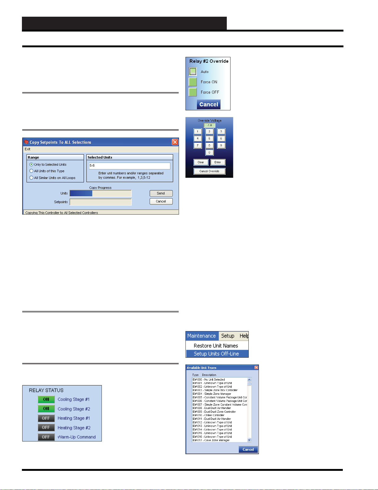
Copy Setpoints
To copy setpoints from one controller to all other controllers or
selected controllers on your installation, select
<Copy to ALL>
from the Top Menu Bar of the designated setpoint screen.
NOTE: There are a few controllers that do not allow the <Copy
To All> feature to operate since critical hardware confi gurations
copied to another similar controller on a different piece of
equipment could cause equipment failure.
You have three copy options:
1. You can copy only to selected units on the same loop by
entering individual addresses or groups of addresses such
as the above example of 5-6.
2. You can copy to all similar units located on the same
communications loop.
3. You can copy to all similar units located on any installed
loops on your installation.
Click < Send> to perform the copy function.
WARNING: WattMaste r Controls, Inc. does not assume a ny
responsibility or liability due to misuse or misunderstanding
of this feature. Copying setpoints to or from units that do not
have ident ical com ponent s can r esult in con sidera ble dam age,
e.g. from a unit with four compressors to a unit with two
compressors.
Output Overrides
Some controllers allow you to
manually override a relay or
analog output to any condition
you wish. You must exercise
caution when forcing outputs,
because you have the potential
to damage equipment by
short-cycling compressors or
performing other undesired
control settings.
If your controller supports relay overrides,
clicking on a relay indicator will cause a box
similar to the one at left to appear.
Clicking on an analog override will display
the Override Voltage Box as shown below
at left.
Any voltage between 0.0 and 10.0 volts is
considered valid and will force the output
to that value. To cancel an override, click
< Cancel Override> or enter a -1.0 value for
the Override Voltage.
Prism 2 will maintain relay and analog output
overrides for as long as communications
are open to your system. If you close
communications or the Prism 2 program, the
overrides will time-out after 10 minutes.
If you set an override from your computer, no one else will be able
to change that override from their computer. Only the initiating
party can clear or change an override condition.
Refreshing the Screen
Once you have confi gured a unit, you may have to click the
< Refresh> button found on Prism 2’s Top Toolbar to have the new
confi guration appear on the unit’s status screen.
Confi guring Units Off-Line
You can set up units off-line in the event you cannot access
controllers. For example, you can set the controllers up in your
offi ce prior to going to a job-site and save the entered setpoints to
a fi le. When you get to the job-site, you simply click < Restore> in
each controller’s setpoint screen and open the saved setpoints fi le.
To confi gure units off-line, click
< Setup Units Off-Line> from the
Maintenance Menu.
Click anywhere in the Unit
Selection Window on the Main
Screen and the Available Unit
Types Window will pop up. Use
the scroll bar to scroll through and
select the unit type that you want
to confi gure. When you click on
the unit type, the unit controller’s
setpoint screen will appear.
Enter all setpoints and save the
fi le, giving it a unique fi le name
associated with a location at your
job-site, e.g. Bill’s offi ce.
26
Prism 2 Technical Guide
Page 27

STEP 8: CONFIGURING ALARMS
Configuring Alarms
Step 8: Configuring Unit Alarms
You can confi gure which alarms can generate call-
outs or e-mails by accessing the Unit Alarm Screen
for each controller on your system. The Unit Alarm
Screen is accessed from each controller’s status
screen by clicking the < ALARM> button. This button will be a dull
red and display < No Alar ms> when there are no alarms present
or will be bright red and display <ALARM> if active alarms exist.
Click the <ALARM> button when bright red or the <No Alar ms>
button when dull red. The Unit Alarm Status & Confi guration
Screen will appear.
Below is a sample Unit Alarm Status & Confi guration Screen. This
screen also displays the Alarm Status for each enabled alarm. Each
individual <ALARM> button will be bright red if an alarm exists
and will be gray if no alarm exists or if the alarm is not enabled.
You must check the box associated with each alarm in order for
the system to alert you of each alarm. You must also select Alarm
Polling Enabled in the Job Sites Window in order for Prism 2 to
actively poll for alarms.
If there is an active alarm condition, it will be indicated by the
<ALARM> button located in the upper right corner of the Prism 2
Main Screen.
You can always view all active alarm conditions for a specifi c
controller from its individual status screen, but only alarms
designated for notifi cation will appear on the Prism 2 Main Screen
alarm display. The Alarm display is described in detail in the
section “Alarm Polling” on page 28.
Prism 2 Technical Guide
27
Page 28
STEP 9: POLLING FOR ALARMS
Alarm Polling
Step 9: Alarm Polling
NOTE: This section applies to Prism 2 Alarm Polling only. F or
System Manager Touch Screen Alarm Polling, see Appendix E.
Prism 2 can be confi gured to poll the system consistently for alarm
information reported by each installed controller. For the system to
poll for alarms, you must have Alarm Polling Enabled checked in
the Job Sites W indow.
Only the alarms that have been previously confi gured on the Unit
Alarm Status & Confi guration Screen for each type of controller
will activate an alarm in this display window. Alarms not confi gured
will only be reported on the Unit Alarm Status & Confi guration
Screen accessed from each individual controller’s status screen.
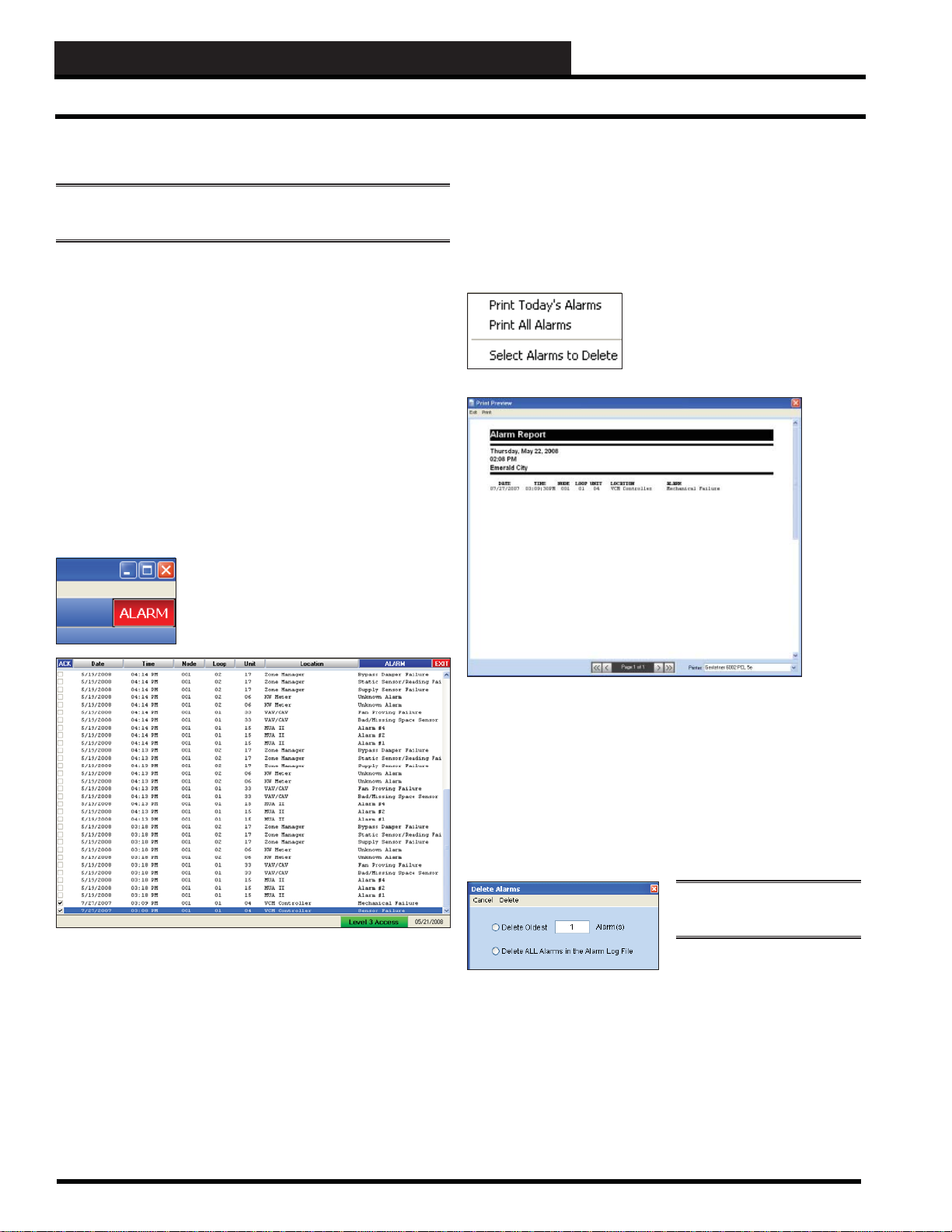
Whenever Prism 2 indicates it is On Line, it will poll the system
every 30 seconds for new alarm conditions. If any new alarms are
detected on the system, the Alarm Indicator located in the upper
right corner of the Prism 2 Main Screen will turn red and display
< ALARM>.
When you click on the alarm indicator, the
Alarm Display will appear on the Main
Screen with a list of the new alarms and any
old alarms still left in the alarm log fi le.
Acknowledging the alarms lets the system know you have been
notifi ed and are fi xing the problem.
To acknowledge all alarms, click the blue
checkmark will appear in front of each alarm.
For printing and deletion options, click the blue < ALARM> button,
and the following menu will appear:
To print just the alarms that have
come in today, select the fi rst option
< Print Today’s Alarms>. Y ou should
see a Print Preview Window like the
one shown below.
< ACK> button. A
Alarms are displayed with the newest ones appearing at the top
of the list. This sample list shows two old alarms that have been
acknowledged with a checkmark and numerous alarms that have
not been acknowledged yet.
The Date and Time of the alarm are recorded when Prism 2 actually
polls and receives the alarm condition. It does not accurately refl ect
when the alarm occurred unless Prism 2 is left running continuously
and can log the alarms as they occur.
The printer you actually send it to can be selected in the lower right
corner.
If you select < Print All Alarms>, all old and new alarms that still
exist in the alarm log will be sent to the Print Preview Window for
printing.
To keep the alarm log fi le from growing too large, you can delete
specifi ed alarms from the log by selecting < Select Alarms to
Delete>. The following window will appear .
NOTE: Only a Level 3 user
can delete alarms.
You can delete the oldest
alarms that no longer need to
be maintained, or you can delete the entire alarm log fi le and start
fresh. Once you make your selection, click < Delete>.
You should periodically delete logged alarms because the fi le can
grow quite large and can slow down the system.
28
Prism 2 Technical Guide
Page 29

STEP 10: TREND LOGGING & PRINTING
Trend Logging
Step 10: Trend Logging and Printing
Before you select this option, you should close any other
open status, setpoint, or diagnostic screens. To display
trend log data, from the Prism 2 Main Screen Top
Toolbar, click the < Logging> button.
NOTE: You can also view a un it’s tr end logs by clicking the
< Trendlogs> button from the Top Menu Bar of a unit’s
in di v i d u a l st a tu s s c re e n .
The Trend Logs Screen will open. It will be empty until you select a
menu option. The name of the controller you were viewing before
you accessed this screen will be displayed in the Title Bar. If you
weren’t viewing a controller, the fi rst unit on the fi rst loop would be
designated in the Title Bar.
T o view recent data, click
load with the most recent log data.
Report appears as follows:
Please note that there may be more than one page. You can scroll
through pages with the page scroll at the bottom of the screen.
To view previously saved log fi les, click <Select Log>. The Log
Selection Window will appear. Prism 2 will search the folder of the
specifi ed unit to determine which days of the year a log has been
saved. If you are auto-logging, every day of the year will display
in red.
<Load Log>. The Trend Log Report will
An example of a Trend Log
You can change the controller by
clicking < Select Unit>. The Select
Unit Dialog Box will appear as
displayed at left.
Highlight the Node, Loop, and Unit
of the desired Controller. The Unit
Address and Name should now
appear in the Tr end Logs Scr een T itle
Bar.
Once you have selected the desired
unit, you can either load the most
recent log data by selecting < Load
Log> or load previously stored logs
by selecting < Select Log>.
From this screen you can see highlighted days of the year
(represented with a red background) that indicate a log was saved
for this controller on that day. Click on any highlighted date to load
the data.
Prism 2 Technical Guide
29
Page 30

STEP 10: TREND LOGGING & PRINTING
Printing Trend Logs
T o print a log, fi rst select a printer from the Default Printer Selection
Dialog Box located at the bottom right of the Trend Logs Screen
and then click < Print>. Every time you open Prism 2, this printer
selection will be the default printer until you change it.
NOTE: If y o u s e l e ct a prin te r fro m thi s li st b o x , i t wi ll be co m e
the default printe r for all programs on your computer u nless
you select a different pri nt e r in Prism 2 or fr om the Windows®
Control Panel.
To graph data from a log, click < Graph>. The Log Selection
Window will appear again. Select a highlighted date to graph. The
Trendlog Graph Screen will fi ll up your entire computer display.
Click <Exit> to return to the Trend Log Screen.
If you would like to export a day’s worth or month’s worth of
log data for further analysis not provided in Prism 2, select either
< Export Daily> or < Export Monthly>. Prism 2 will create a
comma delimited . CSV fi le that can be opened in most spreadsheet
and database applications.
If you select <Export Daily>, the process is done automatically.
Prism 2 will display the fi le name and location created for the
exported data.
If you select <Export Monthly>, the following dialog box will
appear:
NOTE: Some cont rollers don’t have the ability to creat e line
charts of the logged data. If this is the case, Prism 2 will display
one or more message boxes informing you that it cannot display
line graphs.
Below is a sample line graph display from a Variable Air Volume
Box Controller.
Select a month from the Selected Month drop down box, select
a year from the Selected Year scroll box, and then click < Begin
Processing>. When the processing is done, the message DONE
will appear in the bottom status bar of the window. Your data will
be saved in your Prism 2 directory within a new subfolder titled
Export.
30
Prism 2 Technical Guide
Page 31

STEP 10: TREND LOGGING & PRINTING
Viewing History and T enant Logs
File Menu
There are four options located under the File Menu—
< View History Log>, < View Tenant Logs>, < Print Unit
Descriptions>
function is described on page 9.
, and < Edit Passcodes>. The <Edit Passcodes>
View History Log
Prism 2 tracks most user interactions such as logging on and off,
changing setpoints, acknowledging alarms, etc. These are selected
and displayed on the History Logs Screen when you click <View
History Log> from the File Menu and choose a month and year:
View Tenant Logs
To view tenant logs for a selected loop and month, click <View
Tenant Logs> from the File Menu. Y ou must click < Load> for the
data to post in the empty window.
T o print the logs, select < Print>.
Print Unit Descriptions
To obtain a hard copy of installed units and their descriptions,
click <Print Unit Descriptions> from the File Menu. The Print
Preview Screen will appear, allowing you to preview the printout
before actually sending it to the printer. Only loops with installed
units will be presented for printing.
History Logs are encrypted and cannot be viewed or modifi ed by
other programs. A permanent monthly record is maintained, and
new fi les are created each year so that logs from previous years can
still be viewed at any point in time.
Prism 2 Technical Guide
31
Page 32

STEP 11: TENANT OVERRIDE LOGGING
T enant Override Logging
Step 11: Tenant Ov erride Logging
This is an optional confi guration that allows a building owner to
log the amount of time per month that selected controllers on a
loop have been put into the Unoccupied Override Mode. From
this information, tenants can be billed for additional energy usage
beyond normal Occupied operation.
In order to set up T enant Override Logging to work with the System
Manager TS, you must have a CommLink and MiniLink Polling
Device installed on your system. The following procedure must be
done for the MiniLink Polling Device on each loop.
In the Loop Selection Window of the Prism
2 Main Screen, select the loop where your
MiniLink Polling Device is located. Then,
in the Unit Selection Window scroll down to
Address 60 - MiniLink PD and click once
on your selection.
Click the < Tenant Logging> option at the top far right of the
Polling Device Setpoints Window. The Tenant Logging Window
will appear.
The Polling Device W indow will appear.
Click <Setpoints> at the top of the screen. The Polling Device
Setpoints Window will appear.
32
Revised 8/29/11
In the Tenant Logging Window, click the box to the left of each
controller to choose tenant logging for that controller. A check
mark in the box designates that the unit will be polled for Tenant
Logging.
Prism 2 Technical Guide
Page 33

STEP 12: CREATING CUSTOM SCREENS
Overview
Step 12: Creating Custom Screens
Once all units have been detected and named and the system is
up and running, you can begin creating your own custom status
screens using the built-in Graphics Editor.
You can create simple fl oor-plans, summary screens, and even
screens containing an equipment photograph with temperatures
overlaid on the equipment.
Not all status fi elds on the standard status screens are available on
custom screens. But you can place temperatures, damper positions,
carbon dioxide, and other similar types of readings. You can also
add an alarm indicator for specifi ed units. Some items that cannot
be displayed are occupied/unoccupied modes, fan status, or any
other binary style of data.
T o access Custom Screens, click <Custom> on the Prism
2 Main Screen Top Toolbar. You must have a Level 3
passcode to access this item.
From the Custom Screens Window’s
File Menu you can start new custom
screens, edit existing screens, or open
a custom screen for viewing live data.
To start a new screen, click < New
Screen> from the File Menu.
Selecting <New Screen> will clear
any old screen data if any exists or
will refresh the memory to begin a
new screen. Before you start, it’s a good idea to create a fi lename
for the screen you are about to create.
Click < Save Screen> from the File Menu to open the File Save
Window.
At the top of the Custom Screens W indow is the Placement T oolbar .
To see a text message overview of a button’s function, hold the
mouse cursor over a button without clicking.
Following is a quick overview of each Placement Toolbar button’s
function and when it should be used.
Align Left: Use this button to align a group of selected
text or data boxes with the left edge of the left most
selected item.
Align Right: Use this button to align a group of selected
text or data boxes with the right edge of the right most
selected item.
Align Tops: Use this button to align a group of selected
text or data boxes with the top edge of the uppermost
selected item.
Align Bottoms: Use this button to align a group of
selected text or data boxes with the bottom edge of the
lowermost selected item.
Equal Vertical Space: Use this button to equalize the
vertical spacing between a group of selected text or data
boxes. Boxes are equally spaced between the uppermost
and lowermost selected items.
Equal Horizontal Space: Use this button to equalize
the horizontal spacing between a group of selected text
or data boxes. Boxes are equally spaced between the left
most and right most selected items.
Equal Height: Use this button to make all selected items
the same height as the uppermost and left most selected
item.
In the example above, you can see we gave the screen the fi lename
SampleScreen in the Selected File box. This sample screen will be
saved in the main Prism 2 directory once you click <Sav e>. <Open
Screen> defaults to the main Prism directory, so if you save your
fi le to a different folder or drive, you will have to remember where
you saved it.
Prism 2 Technical Guide
Equal Width: Use this button to make all selected items
the same width as the uppermost and left most selected
item.
Place Data: Use this button to place a new data fi eld
on the screen. New data fi elds are always placed in the
upper left corner of the screen and you will need to move
them to the desired location. If you place several data
fi elds at one time, they will overlay on top of each other
until you drag them apart for placement.
Place Text: Use this button to place a text fi eld on the
screen. As with the data fi elds, these will always be
initially place in the upper left corner. You will need to
move them to the desired location.
33
Page 34
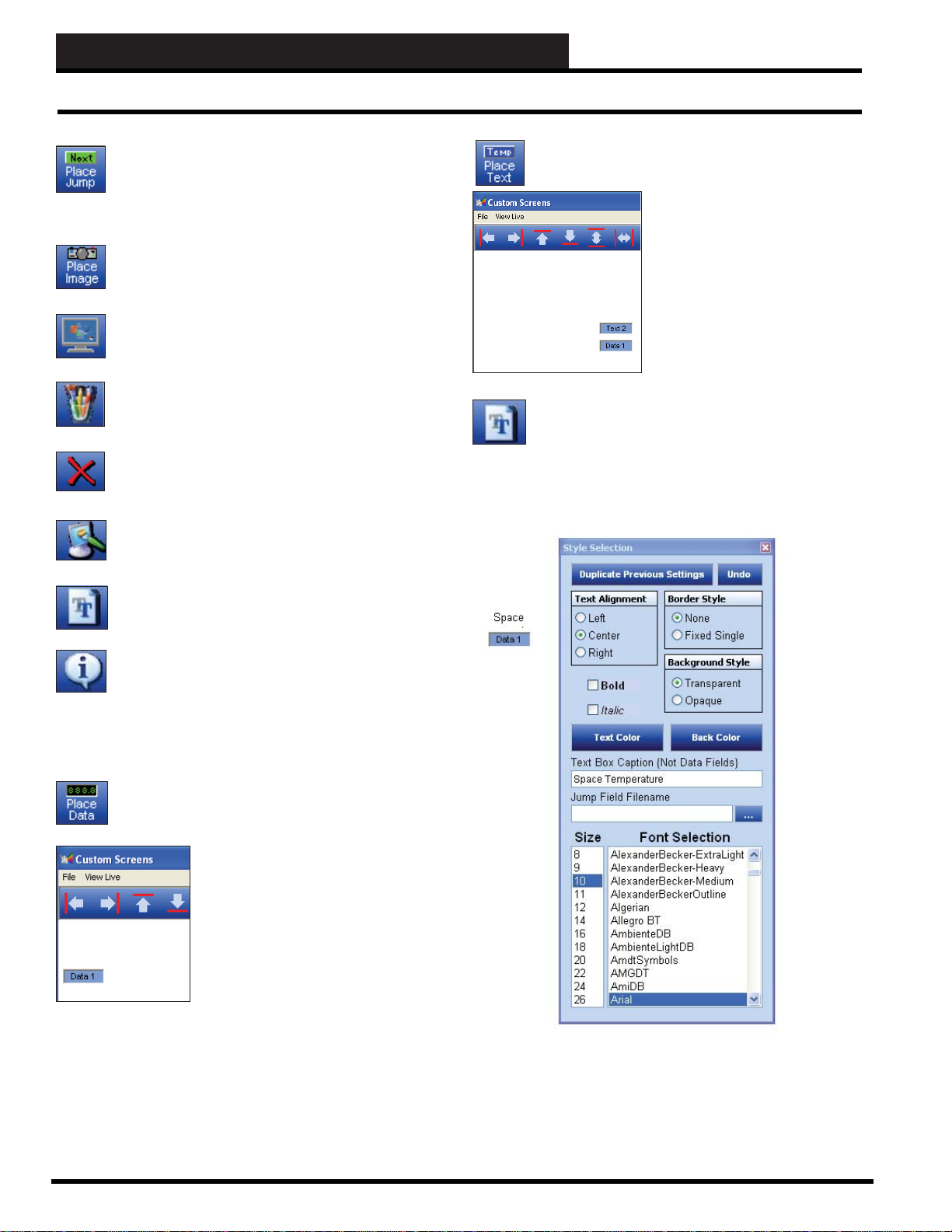
STEP 12: CREATING CUSTOM SCREENS
Creating a Sample Screen
Place Jump: Place a Jump button on your custom
screen if you want to directly jump to other custom
screens from this screen. You can place a Jump button
on any of those screens to jump back to this originating
screen.
Place Image: Use this button to select and load a graphic
image onto the background of your custom screen.
Background Color: If you are not placing any
background pictures, use this button to select a
background color for your custom screen.
Edit Bitmap: Use this button to edit the loaded graphic
image if it is in a format that is readable by the Microsoft®
Paint program.
Cut or Delete Item: If you placed a text or data fi eld
by mistake, you can delete it from the screen with this
button.
Clear Screen: Use this button to clear the screen
completely of all items.
Edit Te xt/Jump: Use this button to edit and format text.
This button is also used to designate Jump fi eld fi les.
Now click on the < Place Text> button to place a text
fi eld on the screen.
Move the text fi eld above the data
box the same way you moved the
data fi eld. Your screen should now
look like the one shown at left.
Let’s say you want a Space
Temperature data fi eld and want
the text box to identify it. The next
step is to change the text in the
T ext Box and also its appearance to
identify the data fi le.
Click the box labeled Text 2 and then click the
Te xt> button.
The Style Selection Window will appear. This window allows you
to change the appearance and the actual text in the T ext Box. Make
the selections shown in the example.
< Edit
Edit Data: Use this button to edit and format data.
Creating a sample screen
Click the < Place Data> button.
A new data fi eld labeled Data 1 will
appear in the upper left corner of the
screen.
Y ou can left-click the box, hold the mouse
button down, and drag it to a new location.
34
Prism 2 Technical Guide
Page 35
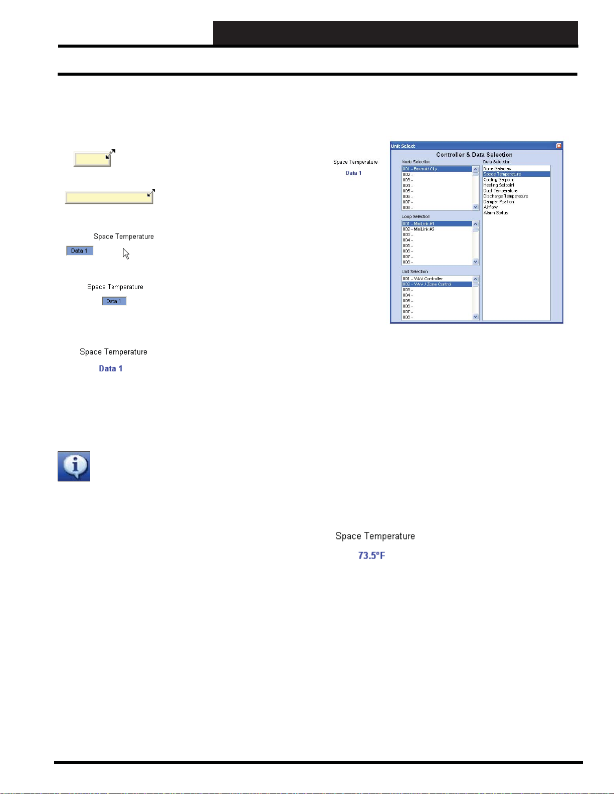
STEP 12: CREATING CUSTOM SCREENS
Save Screen and View Live Screen
You should have changed the appearance of the text in the text box
and changed the text to read Space Temperature. You will notice
that only the word Space can be seen. You need to re-size the text
box so that both words appear.
Right-click on the word Space. The text box will
change to yellow and drag handles will appear.
Keep holding the right mouse button
down and drag the text box so that
it is large enough to contain the
words Space Temperature. Now
click your mouse outside of the text
box and the yellow appearance will
disappear.
Now that the text box is correctly
sized, left-click on it and drag it
to the left to center it on top of the
Data 1 box.
Now format the Data 1 box to
remove the border and background
color. Use a bold font and change
the text color to blue (or any desired
color) to indicate a data fi eld.
Now you need to assign a data point to the Data 1 box so that the
program knows which controller to read the Space Temperature
from.
Click on the Data 1 box and then click the
button.
<Edit Data>
The Unit Select Window will appear. Remember, you must have
previously performed a Search For Units or manually confi gured
units before this function will work properly.
In the example above, the second Controller on Loop #1 along with
the Space T emperature data point is selected. Once the data point is
selected, this window will automatically close. If you re-open this
window on a previously defi ned data box, it will show the selected
unit and data point.
Now that you have formatted your text and data box and assigned
a data point, you should save the fi le and then test it to see if live
data actually appears.
Click <Save Screen> from the File Menu to save this custom
screen. Next, click < View Live> to activate the File Open Window
so that you can select which custom screen to view. Reselect this
SampleCustom.CUS screen fi le.
Prism 2 Technical Guide
If you are On Line and connected
to your system, you should now see
live data appear from the selected
controller as shown at left.
You can left-click on any active data fi eld displaying live data and
be taken to the status screen for the controller. When you close the
status screen, you will automatically return to the previous custom
screen you had open.
35
Page 36

STEP 12: CREATING CUSTOM SCREENS
Placing a Jump Field
Miscellaneous Edit Functions
The following is a quick overview of some of the other editing
buttons you did not use in the creation of your fi rst sample screen.
The alignment and sizing buttons
require selection of multiple text
and data fi elds. Selecting multiple
items is as simple as left-clicking
in the uppermost and leftmost
position you want to select and
then dragging the outline box
around the controls you want
selected before releasing the
mouse button.
Once you release the button, the selected
text will be gray and the fi elds will be
surrounded by dashed lines.
Now you can align all three boxes to the
left or right, space them equally, or even
drag all three to a new location if you
click and hold inside the original outline
you made to select these three fi elds.
Placing a Jump Field
Let’s say you have built a custom screen of space temperatures
from several zone controllers and you would like to jump to
another fl oor plan or maybe to an Air Handler Screen for the unit
that services these zones.
Click the < Place Jump> button to place a jump box
in your custom screen. Left-click on the jump box and
then click the < Edit T ext> button to select the jump fi eld
fi lename in the Style Selection Window.
In the example that follows, a Jump button was created called
AHU, and whenever it is selected, the program will jump to a fi le
called SampleScreen.CUS. In this manner, you can link fl oor plans
or campuses or equipment in logical groups and access them with a
single button click instead of manually selecting the fi lename from
the File Open Window.
NOTE: The program always aligns items with the top left most
item no matter which alignment option you choose.
Once you have fi nished aligning, sizing, or moving these controls,
you can deselect them by clicking anywhere on the outside of the
original box you outlined to select the fi elds.
In the SampleScreen.CUS screen and each preceding screen, you
would want to create a Jump button to jump back to the fi rst screen
and so on.
36
Prism 2 Technical Guide
Page 37

STEP 12: CREATING CUSTOM SCREENS
Placing an Image
Placing an Image
If you want graphics displayed along with the data and
text, click the < Place Image> button to open a File
Open Window and load a graphic onto the form. The
fi le format is limited to BMPs, JPEGs, and GIFs.
Prism 2 always places the graphic in the upper left corner of the
custom screen, so if you have a small graphic, you may want to edit
it and make it larger so that the graphic appears more centered on
the screen resolution you are currently using.
To edit the graphic, click the < Edit Bitmap> button to
launch the Windows® Paint program or use your own
graphics program and then reload the graphic when you
are fi nished.
The sample screen that follows shows a bitmap in the background
with three data fi elds, three text fi elds, and one Jump button <First
Floor> placed so that you can jump back to the custom screen that
you originated from.
Main Screen Image Hot Spot
Selection
To immediately access different job sites or custom screens, an
Easy Access Hot Spot can be created for each job-site on Prism 2’s
Main Screen image.
You can associate a custom screen with a job-site in the Job Sites
Window’s Custom Screen fi eld and then you can create a link or
hot spot on the Prism 2 Main Screen to automatically access that
job-site’s custom screen.
From the Prism 2 Main Screen, right-click anywhere inside the
main screen area. In our example, we have a map of Kansas City
as our Main Screen Image.
The message, “Drag an Area on the Graphic to create a HOT SPOT
Selection Window” will appear in red in the Lower Toolbar.
To select the whole image, position the mouse in the upper left
corner of the image, hold the left mouse button down, and drag
the selection box to the lower right corner. In our example, we will
select a small area surrounding the star that indicates a job-site
location on the map.
As you can see, the dashed lines create
a border around the star, making this
the only area on the map currently
selected as the Easy Access Hot Spot.
Once you release the left mouse button,
the Hot Spot Job Selection Window
will appear:
Prism 2 Technical Guide
37
Page 38
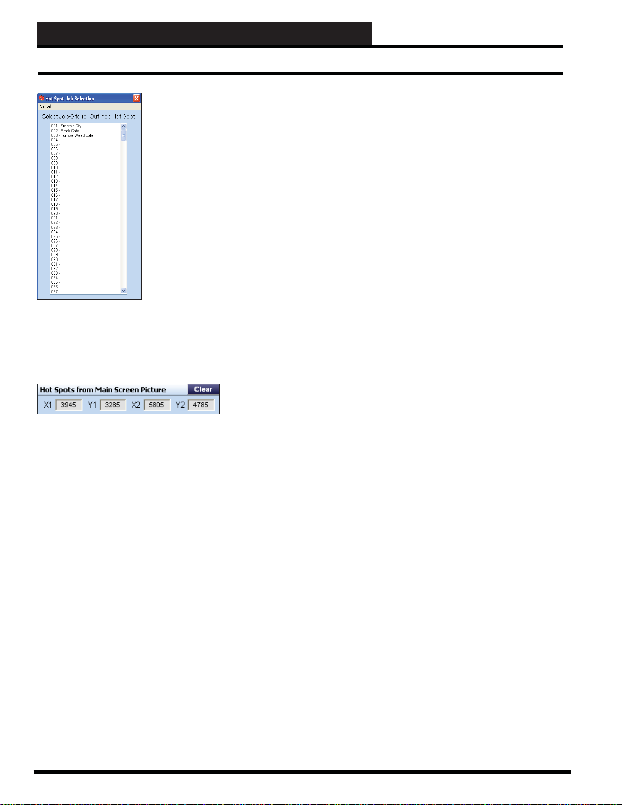
STEP 12: CREATING CUSTOM SCREENS
Hot Spots
Click on the job-site you wish to be
associated with this hot spot. As soon
as you click the job-site, the window
will close.
Multiple Hot Spots can be created
on the Main Screen Image, and each
hot spot can be associated with any
defi ned job-site listed in the Hot Spot
Job Selection Window.
In the future, all you need to do to
access your job-site is to click where
you placed its hot spot on the Main
Screen Image.
To clear a Hot Spot associated with a job-site, open the Job Sites
Window for that job-site and click the
Spots for Main Screen Picture fi eld.
< Clear> button in the Hot
38
Prism 2 Technical Guide
Page 39

APPENDIX A - SCREEN EXAMPLES
Status and Setpoint Screen Examples
Zone Controller Status Screen:
Zone Controller Alarm Status and Configuration Screen:
Constant Volume Controller Status Screen:
Constant V olume Controller Alarm Status and Configuration Screen:
Zone Controller Setpoints Screen:
Prism 2 Technical Guide
Constant Volume Controller Temperature Setpoints:
39
Page 40
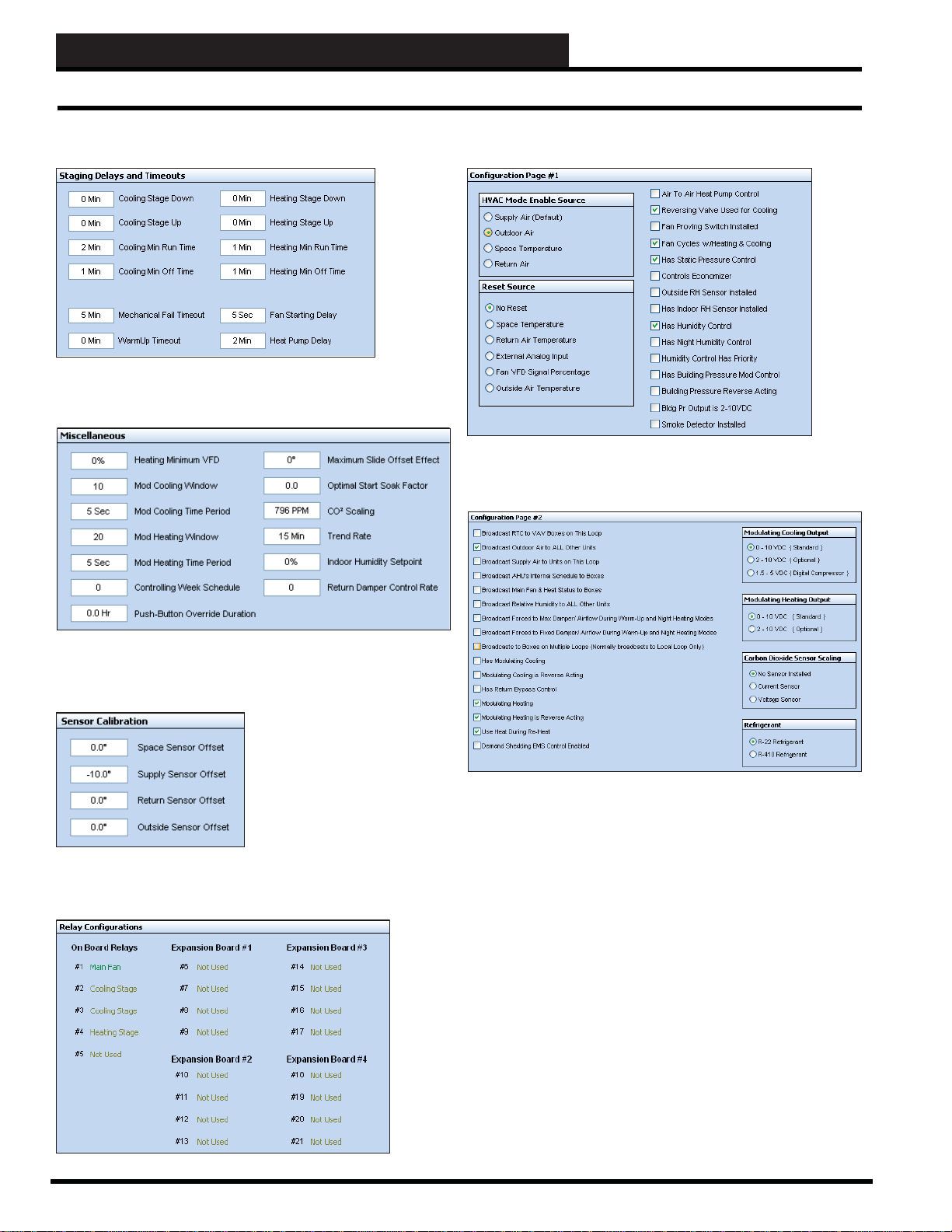
APPENDIX A - SCREEN EXAMPLES
Status and Setpoint Screen Examples
Constant Volume Controller Staging Delays and Timeouts Setpoints:
Constant Volume Controller Miscellaneous Setpoints:
Constant Volume Controller Configuration Setpoints - Page 1:
Constant Volume Controller Configuration Setpoints - Page 2:
Constant Volume Controller Sensor Calibration Setpoints:
Constant Volume Controller Relay Configuration Setpoints:
40
Prism 2 Technical Guide
Page 41

APPENDIX B - DEMOMODE
DEMOMODE Setup and Operation
DEMOMODE Setup and Operation
DEMOMODE is a set of fi les that allow you to view samples of
controller status and setpoint screens without having to connect
to a live system. You may want to be able to demo the Prism 2
program to a customer, for example.
The DEMOMODE fi les are available for download from all of
our WattMaster Controls websites under Software. DEMOMODE
is individualized for each of our control systems. You can access
all of our websites from our main website—www.wattmaster.com.
When you download the DEMOMODE fi les, make sure you copy
the fi les into the Confi guration subfolder in your main Prism 2
directory.
To run DEMOMODE, simply select an empty job-site location in
your Prism 2’s Job Sites W indow and type in DEMOMODE just as
it is - one word, all caps - in the Selected Location fi eld and pr ess
<ENTER>.
The DEMOMODE fi les will automatically confi gure one of each
type of controller included for viewing. No communications will
occur, but all status and setpoint screens related to that unit will be
available for viewing.
Exit the Job Sites Window and click on DEMOMODE in the
Site Selection Window of the Prism 2 Main Screen. Once you do
this, the controllers available for viewing will appear in the Unit
Selection Window.
Prism 2 Technical Guide
NOTE: Unless you are using your computer strictly for
DEMOMODE, you should not use the fi rst job-site location
for DEMOMO D E unless you don’t mind the inconvenience of
having to manually select a different job-site location each time
you start Prism 2.
41
Page 42

APPENDIX C - SYSTEM MANAGER TS ALARM POLLING
Setting Up Alarm Polling f or the System Manager TS
Setting Up Alarm Polling for the
System Manager TS
NOTE: This section applies to System Manager T ouch Screen
Alarm Polling only . For Prism 2 Alarm Polling, see Section 9 .
Using Prism 2 to set up Alarm Polling for the System Manager
TS, you must have a CommLink and MiniLink Polling Device
installed on your system. The following procedure must be done
for the MiniLink Polling Device on each loop.
In the Loop Selection Window of the Prism
2 Main Screen, select the loop where your
MiniLink Polling Device is located. Then,
in the Unit Selection Window scroll down to
Address 60 - MiniLink PD and click once
on your selection.
Click the <Alarm Polling> option at the top far right of the Polling
Device Setpoints Window. The Alarm / Override Polling Window
will appear.
The Polling Device W indow will appear.
Click <Setpoints> at the top of the screen. The Polling Device
Setpoints Window will appear.
42
Revised 8/29/11
In the Alarm / Override Polling Window, click the box to the left of
each controller to choose alarm polling and push-button overrides
for that controller. A check mark in the box designates alarm
polling/push-button override.
Prism 2 Technical Guide
Page 43

INDEX
A-B
9600 baud.......19
19200 baud.......19
A
Access Level.......6, 7
ACK Button.......28
Acknowledging
Alarms.......28
Addresses
59 & 60.......20
Node IP.......10
Alarm
Acknowledging.......28
Callout Cell / Pager Number.......19
Date and Time.......28
Display.......28
E-Mail Notifi cation.......12
Indicator.......28
Log.......28
Maintenance.......28
Polling.......12
Printing.......28
Status.......27
Alarm Button.......6
Controller Status Screen.......23
Main Screen.......28
Alarm Polling.......42
Alarm Polling Enabled.......11
Align Bottoms Button.......33
Align Left Button.......33
Align Right Button.......33
Align Tops Button.......33
Analog Override.......26
Asterisks.......9
Auto-Logging.......14
Auto-Log Retrieve Times Window.......14
Auto Re-Start After Power Failure.......16
Auto Scheduling.......23
Auto-Zone Setpoint Verifi cation.......11
Auxiliary
A vailable Unit Types Window.......26
, Defi ned.......12
, 27, 28
, 7, 27
, 27, 28
, 29
B
Background Color Button.......34
Background Tasks.......7
Baud Rate.......19
Begin Processing Button.......30
Bitmaps.......37
Blue ALARM Button.......28
BMP.......17
Bottom Status Bar.......6
Broadcast Time to Keep Controllers Synchronized.......16
, 37
, 7
Buttons/Icons
ACK.......28
Alarm.......6
ALARM.......27
Align Bottoms.......33
Align Left.......33
Align Right.......33
Align Tops.......33
Background Color.......34
Begin Processing.......30
Blue ALARM.......28
Cancel Dialout.......18
Cancel Force Modes.......22
Cancel Override.......26
Cancel Search.......20
Clear Hot Spot.......38
Clear Screen.......34
Copy Holidays to All.......24
Copy Schedule to All.......23
Copy to All.......22
Custom.......6
Custom Screens.......7
Cut or Delete Item.......34
Delete.......28
Delete Job-Site.......14
Dial-Out.......7
Edit Bitmap.......34
Edit Data.......34
Edit Text.......36
Edit Text/Jump.......34
Equal Height.......33
Equal Horizontal Space.......33
Equal Vertical Space.......33
Equal Width.......33
Erase Holidays.......24
Erase Schedules Button.......23
Export Daily.......30
Export Monthly.......30
Graph.......30
Hang Up.......18
Holidays.......23
Holiday Schedule.......24
Job-Site.......6
List.......6
Load.......18
Load Log.......29
Logging.......6
Login.......6
Log Times.......14
Log Units.......15
No Alarms.......27
On Line/Off Line.......5
Override.......23
Place Data.......33
, 7
Controller Status Screen.......23
, 28
, 33
, 11, 18
, 10
, 7, 21
, 31
, 7, 29
, 7, 8
, 24
, 25
, 37
, 6, 7, 18
Prism 2 Technical Guide
43
Page 44

INDEX
B-C
Place Image.......34, 37
Place Jump.......34
Placement Toolbar.......33
Place Text.......33
Print.......22
Refresh.......6
Restore.......19
Restore Holidays.......24
Restore Schedule.......23
Restore Setpoints.......22
Save Holidays.......24
Save Schedule.......23
Save Setpoints.......22
Schedule.......23
Select Log.......29
Select Unit.......29
Send.......24
Setpoints.......22
Start Search.......20
Tenant Logging.......32
Trendlogs.......22
UNIT ALARM.......27
Weather.......6
, 36
, 7, 26
, 24
, 25
, 24
, 25
, 26
, 29
C
Calculating
Log Times.......14
Cancel
Cancel Override Button.......26
Cancel Search Button.......20
Dialout.......18
Force Modes.......22
Cell Phone.......19
Check Unit Maps.......20
Clear Hot Spot Button.......38
Clear Screen Button.......34
CommLink
Auxiliary.......12
ID Number.......19
IP Web Settings.......18
IV & 5 w/IP.......11
Multiple.......11
Multiple Loop.......12
Saving Settings.......19
Settings Window.......18
Setup.......18
Single Loop.......12
CommLink 5.......11
CommLink 5 Technical Guide.......10
Communications
Set Up.......18
Communications Menu.......6
CommLink IP Web Settings.......18
, 15
Search For Units.......20
Setup CommLink.......18
Start AutoLog.......14
Communications Port.......18
COM Port #9.......10
Computer
Hard drive.......3
Monitor.......3
Network Card.......3
Pentium 2 GHz Processor.......3
Pentium 4 2 GHz Processor.......3
Software License.......3
Confi guration Dialog Box.......16
Confi guring
Controller Alarms.......27
Controllers.......22
Custom Screens.......33
Prism 2.......16
Setpoints.......22
Unit Alarms.......27
Zone Controllers.......22
Confi guring Prism 2.......16
Confi guring Units.......22
Confi guring Units Off-Line.......26
Confi guring Zone Controllers.......22
Connection.......6
Internet.......11
Modem.......11
Remote Job-Site.......18
TCP/IP.......18
Constant Volume Controller
Alarm Status and Confi guration Screen.......39
Confi guration Setpoints.......40
Miscellaneous Setpoints.......40
Relay Confi guration Setpoints.......40
Sensor Calibration Setpoints.......40
Staging Delays and Timeouts Setpoints.......40
Temperature Setpoints.......39
Controllers
Alarms, Confi guring.......27
Alarm Status Button.......23
Confi guring.......22
Confi guring Off-Line.......26
Holiday Setting.......23
Off-Line.......26
Override.......23
Renaming.......21
Schedule.......23
Selecting.......21
Setpoints.......25
Start and Stop Time.......23
W eekly Time Schedules.......23
Copy Holidays to All Button.......24
Copy Range Box.......24
Copy Schedule to All Button.......23
, 7
, 18
, 24
44
Prism 2 Technical Guide
Page 45

INDEX
C-E
Copy Selected Units Box.......24
Copy Setpoints
Only to Selected Units.......26
To All Similar Units Located on All Loops.......26
To All Similar Units on the Same Loop.......26
WARNING.......26
Copy to All.......22
Button.......25
Holidays.......24
Schedule.......23
Crossover Cable.......11
CSV File.......30
Current Date.......6
Current Unit
Search For Units Screen.......20
Custom Button.......6
Custom Screens
Align Bottoms.......33
Align Left.......33
Align Right.......33
Align Tops.......33
Background Color.......34
Button.......7
Clear Screen.......34
Creating.......33
Cut or Delete Item.......34
Display Picture.......13
Edit Bitmap.......34
Edit Data.......34
Edit Text.......36
Edit Text/Jump.......34
Equal Height.......33
Equal Horizontal Space.......33
Equal Vertical Space.......33
Equal Width.......33
File Menu.......33
Jump Field.......36
Linking.......36
Live Data.......35
Miscellaneous Edit.......36
Place Data.......33
Place Image.......34
Place Jump.......34
Place Text.......33
View Live.......35
Window.......33
Cut or Delete Item Button.......34
Cycle Power.......19
, 24
, 7
, 33
, 37
, 36
D
Damper Override Window.......22
Data
Data 1 Field
Exporting.......14
Importing.......14
Date and Time
Default Printer Selection Dialog Box.......30
Delete Button.......28
Delete Job-Site.......14
Deleting
DEMOMODE.......40
DHCP.......11
Diagnostics.......8
Dialing Status and Connection Window.......18
Dial-Out.......11
Download
Alarms.......28
Force Damper.......22
Button.......6
Cancel.......18
Hang Up.......18
Procedure for Remote Job-Site.......18
, Custom Screens.......34
Alarm.......28
, 20
, 7, 11, 18
Prism 2.......5
E
Edit
Edit Bitmap Button.......34
Edit Data Button.......34
Edit Text Button.......36
Edit Text/Jump button.......34
Text.......34
Edit User Passcodes Window.......9
E-mail Account
E-mail Address.......12
Edit Passcodes.......9
Encryption.......31
Enter Key.......4
Enter Passcode.......7
Enter Passcode Window.......7
Equal Height Button.......33
Equal Horizontal Space Button.......33
Equal Vertical Space Button.......33
Equal Width Button.......33
Erase Holidays Button.......24
Erase Schedules.......23
Erase Schedules Button.......23
Export Daily Logs.......30
Export/Import Files.......14
Export/Import to Selected Job-Site.......14
Exporting Data.......14
Export Monthly Logs.......30
, Standard.......12
, 31
, 37
Prism 2 Technical Guide
45
Page 46

INDEX
F-H
F
Factory Level Access.......8
Fan Only Mode.......23
Fields
Access Level.......7
Alarm Callout Cell / Pager Number.......19
Alarm E-Mail Notifi cation.......12
Alarm Polling Enabled.......11
Auto-Logging.......14
Auto Re-Start After Power Failure.......16
Auto Scheduling.......23
Auto-Zone Setpoint Verifi cation.......11
Background Tasks.......7
Baud Rate.......19
Broadcast Time to Keep Controllers Synchronized.......16
Cell Phone.......19
Check Unit Maps.......20
CommLink ID Number.......19
CommLink IP Web Settings.......18
Confi gure.......16
Connection.......7
Copy Only to Selected Units.......26
Copy Range Box.......24
Copy Selected Units Box.......24
Copy Setpoints to All Similar Units on Same Loop.......26
Copy to All Similar Units Located on All Loops.......26
Current Date.......7
Current Unit.......20
Custom Screen Display Picture.......13
Default Printer Selection Dialog Box.......30
Export/Import to Selected Job-Site.......14
Fan Only Mode.......23
Force Schedule OFF.......23
Force Schedule ON.......23
Hot Spots from Main Screen Picture.......13
Job-Site List #.......10
Job-Site Name.......10
Loop Selection.......20
Main Screen Picture.......17
Modem Init String.......19
Network Confi guration.......12
Node IP Address.......11
Node Name.......11
Occupied/Unoccupied Indicator.......23
Pager.......19
Phone Number.......11
Print All Alarms.......28
Print Today’s Alarms.......28
Program Status.......7
Restore Unit Names.......21
Search For Units.......20
Search ONLY the Select Loop.......20
Select Alarms to Delete.......28
Selected Loop.......7
, 27, 28
, 19
Selected Month.......30
Selected Name for Unit / Loop Box.......21
Selected Unit.......7
Selected Y ear.......30
Serial Port.......10
Setup CommLink.......18
Setup Units Offl ine.......26
SMPT Server.......13
Socket.......7
Start AutoLog.......14
Tenant Logging Enabled.......11
Type of CommLink.......12
Unit ID#.......7
File Menu.......6
Custom Screen.......33
Edit Passcodes.......9
Print Unit Descriptions.......31
View History Log.......31
View Tenant Logs.......31
Files
Alarm Log.......28
CSV.......30
Encrypted.......31
Export/Import.......14
File Save Window.......33
File
, Time and Date Stamped.......14
Firewalls.......3
Floor Plans.......36
Force Damper.......22
Force Schedule ON/OFF.......23
Forcing Outputs.......26
, 31
, 31
G
GIF.......17, 37
Graph Button.......30
Graphics.......37
Graphics Editor.......33
H
Hang Up.......18
Hard Drive Space.......3
Help Menu.......6
History Logs
Screen.......31
Viewing.......31
Holidays
Button.......23
Controllers.......23
Copy to All.......24
Erase.......24
Programming.......24
Restore.......24
Save.......24
Schedule.......24
46
Prism 2 Technical Guide
Page 47

INDEX
H-M
Holiday Schedule Window.......24
Hot Spot Job Selection Window.......37
Hot Spot Selection.......37
Hot Spots from Main Screen Picture.......13
I
Image Placement.......37
Importing Data.......14
Indicators
Alarm Indicator.......28
Installed Units.......20
Searching for.......20
Internet.......11
IP Address.......7
IT Professional.......3
, 11
J
Job-Site
Button.......6
Job-Site Selection Window.......10
List #.......10
Name.......10
Remote.......11
Selection.......7
Setting Up.......10
Job Sites Window.......7
Custom Screen Field.......37
JPEG.......17
Jump Field.......36
, 7, 10
, 10, 27, 28, 41
, 37
K
Keys, Enter.......4
L
Level 0 Access.......8
Level 1 Access.......8
Level 2 Access.......8
Level 3 Access.......8
Level 4 Access.......8
Line Graph.......30
Linking
Custom Screens.......36
Floor Plans.......36
List Button.......6
List of Units Screen.......21
Live Data.......35
Load Button.......18
Load Logs Button.......29
Load Tenant Logs.......31
Logging.......29
Button.......6
Interval, Described.......14
, 7, 21
, 31
, 32
, 7, 29
Log Times.......14
Log Units.......15
Multiple Nodes.......15
Login.......8
Button.......6
Log Off.......8
Log Selection Window.......29
Log Times.......14
Log Units.......15
Loop
Name.......6
Renaming.......21
Selection List Box.......15
Selection, Search For Units Screen.......20
Selection Window.......6
Lower Toolbar.......6,7
, 7, 8
, 7, 21
M
Main Screen
Bottom Status Bar.......6
Display Picture.......17
Hot Spot.......37
Image.......17
Lower Toolbar.......6
Picture Dialog Box.......17
Top Toolbar .......6
Maintenance
Alarms.......28
Maintenance Menu.......6
Restore Unit Names.......21
Setup Units Offl ine.......26
Manual
Terms and Conventions.......4
Manual Override.......26
Mask.......11
Menu Items
Edit Passcodes.......9
Menus
Communications.......6
File.......6
Help.......6
Maintenance.......6
Printer Selection.......28
Setup.......6
MiniLink Polling Device.......11
MiniLink Polling Device Window.......32
Modem.......11
Connection.......18
Init String.......19
Remote Link.......19
Monitor.......3
Mozilla Thunderbird.......12
Multiple Loop.......18
Defi ned.......12
, 37
, 31
, 7
, 7
, 7
, 32, 42
, 20
, 42
Prism 2 Technical Guide
47
Page 48

INDEX
N-P
N
Network Card.......3
Network Confi guration.......12
New Alarms.......28
New Screen.......33
No Alarms Button.......27
Node
IP Address.......10
Name.......11
Selection Window.......6
, 11
O
Occupied/Unoccupied Indicator.......23
Off Line.......5
Confi guring Units.......26
Restore Setpoints.......26
Saving Setpoints.......26
On Line.......5
On Line/Off Line Button.......6
Outlook Express.......12
Output Overrides.......26
Override
Analog.......26
Button.......23
Controllers.......23
Relay, Manually.......26
Voltage Box.......26
Overrides
Auto Scheduling.......23
Fan Only Mode.......23
Force Schedule OFF.......23
Force Schedule ON.......23
Output.......26
Relay.......26
Window.......23
, 18
, 18
, 7, 18
P
Pager.......19
Paint Program.......37
Passcode Level
1111.......8
2222.......8
9288.......8
Level 0.......8
Level 1.......8
Level 2.......8
Level 3.......8
Level 4.......8
Passcode Level for Scheduling Access.......16
Passcode Level for Space Setpoint Access.......16
Passcodes
Changing.......9
Edit.......9
Entering.......8
Level 3.......8
Levels.......8
System Manager Level.......8
Pentium 2 GHz Processor.......3
Pentium 4 2 GHz.......3
Phone Number.......11
Place Data.......34
Place Data Button.......33
Place Image Button.......34
Place Jump Button.......34
Placement Toolbar.......33
Buttons.......33
Place Text.......34
Place Text Button.......33
Placing an Image.......37
Poll for Trendlogs.......16
Polling Device Window.......32
Polling for Alarms.......11
Port
COM.......10
Number.......10
Number, Maximum.......10
USB.......10
Power Outage.......16
Print
Alarms.......28
All Alarms.......28
Button.......22
Logs.......30
Print Preview Screen.......31
Print Preview Window.......28
Tenant Logs.......31
Today’ s Alarms.......28
Trend Logs.......29
Unit Descriptions.......31
Printer
Default.......30
Selection.......28
Prism
Icon.......5
Original.......3
Prism 2
CD.......5
DEMOMODE.......41
Main Screen.......6
Overview.......3
System Requirements.......3
Program Features.......3
Programming
Controller Setpoints.......25
Holidays.......24
, 19
, 37
, 36
, 27, 28
, 21
, 42
48
Prism 2 Technical Guide
Page 49

INDEX
P-S
Programs
DEMOMODE.......41
Windows Paint.......37
Program Status.......6
, 7
R
Refresh
Button.......6
Status Screen.......26
Relay
Indicator.......26
Overrides.......26
Remote Connection
CommLink Setup.......18
Remote Job-Site.......11
Dial-Out.......18
Remote Link.......19
Remote Link II Technical Guide.......10
Renaming
Controllers.......21
Loops.......21
Units.......21
Reports
Trend Log Report.......29
Restore
Button.......19
Restore Holidays Button.......24
Restore Schedules Button.......23
Restore Setpoints Button.......25
Schedule.......23
Setpoints.......22
Off-Line.......26
Unit Names.......21
Routers.......3
, 7, 26
, 20
, 24
S
Sample Screen
Custom.......34
Save
Holidays.......24
Save Holidays Button.......24
Save Schedule Button.......23
Save Setpoints Button.......25
Schedule.......23
Screen.......33
Setpoints.......22
Schedule
Button.......23
Copy to All.......23
Erase.......23
for Controllers.......23
Restore.......23
Save.......23
, 24
, 24
, 24
, 24
, 24
, 24
Schedules Window.......23
Screen
Refreshing.......26
Resolution........4
Screens
Alarm Display.......28
Constant Volume Controller
Alarm Status and Confi guration.......39
Confi guration Setpoints.......40
Miscellaneous Setpoints.......40
Relay Confi guration Setpoints.......40
Sensor Calibration Setpoints.......40
Staging Delays and Timeouts Setpoints.......40
Status Screen.......39
Temperature Setpoints.......39
History Logs Screen.......31
List of Units Screen.......21
Log Selection.......29
Main.......6
Print Preview Screen.......31
Search For Units Screen.......20
Trendlog Graph Screen.......30
Trend Logs Screen.......29
Unit Alarm Screen.......27
Unit Alarm Status & Confi guration Screen.......27
Zone Controller Alarm Status and Confi guration.......39
Zone Controller Setpoints.......39
Zone Controller Status.......39
Search For Units Screen.......20
Current Unit.......20
Loop Selection.......20
Search ONLY the Select Loop.......20
Secure
System.......9
Select Alarms To Delete.......28
Selected Location.......10
Selected Loop Field.......7
Selected Loop Name.......6
Selected Month.......30
Selected Name for Loop Box.......21
Selected Name for Unit Box.......21
Selected Unit.......6
Selected Unit Field.......7
Selected Y ear.......30
Selecting
Controllers.......21
Loops.......21
Units.......21
Select Log Button.......29
Select Unit Button.......29
Select Unit Dialog Box.......29
Send Button.......24
Serial Port.......10
, 26
Prism 2 Technical Guide
49
Page 50

INDEX
S-U
Setpoints
Confi guring.......22
Controllers.......25
Copy to All.......22
Restore.......22
Save.......22
Saving Off-Line.......26
Zone Controller.......22
Setpoints Button.......22
Set Up
CommLink.......18
Communications.......18
DEMOMODE.......41
Job Sites.......10
Setup Menu.......6
Confi gure.......16
Main Screen Picture.......17
Setup Units Off-Line.......26
Single Loop.......18
Defi ned.......12
Site Selection Window.......6
SMPT Server.......13
Socket.......6
Software License.......3
Start and Stop Time.......23
Start AutoLog.......14
Start Search Button.......20
Static IP Address.......11
Status
Status Screen
Step 11: Tenant Override Logging.......32
Style Selection Window.......34
Summary
Support Information.......3
System
System Manager Passcode.......8
System Manager TS.......42
, 7, 18
Background Tasks.......7
Unit Alarms.......27
Zone Controller.......22
of Program Features.......3
Logging Off.......8
Requirements.......3
, 41
, 36
T
TCP/IP.......3, 10
Address.......11
Connection.......18
Technical Guides
CommLink w/IP.......18
Tenant Logging
Button.......32
Tenant Logging Enabled.......11
Tenant Logs.......31
Load.......31
Printing.......31
Terms and Conventions.......4
Text Edit.......34
Text Message.......19
Time and Date Stamped File.......14
Toolbars
Lower.......6
Placement Toolbar.......33
Top.......6
Trend Logging.......29
Trendlogs.......14
Button.......22
Graph Screen.......30
Report.......29
Viewing.......29
Trend Logs
Printing.......29
Trend Logs Screen.......29
Troubleshooting
Force Damper.......22
Type of CommLink.......12
Type of CommLink Selection Box.......12
, 7
, 29
, 18
U
Uninterruptible Power Supply.......16
UNIT ALARM Button.......27
Unit Alarms
Confi guring.......27
Unit Alarm Screen.......27
Unit Alarm Status & Confi guration Screen.......27
Unit ID #.......6
Unit Names
Restoring.......21
Units
Confi guring.......22
Confi guring Off-Line.......26
Off-Line.......26
Renaming.......21
Selecting.......21
Unit Search.......20
Unit Selection Window.......6
Unit Select Window
Custom Screens.......35
UPS Device.......16
USB.......10
USB-Link.......12
Network.......12
Stand Alone.......12
USB Port.......10
, 7
, 7, 21, 26, 41
, 20
50
Prism 2 Technical Guide
Page 51

INDEX
V-Z
V
VCM Controllers
Confi guring.......22
View History Log.......31
View Live.......35
View Status Only.......8
View Tenant Logs.......31
Voltage
Override.......26
W
WARNING
Copying Setpoints.......26
W attMaster Technical Support.......9
Weather Button.......6
W eekly Time Schedules.......23
Saving.......24
Windows.......3
Alarm Display.......28
Auto-Log Retrieve Times Window.......14
A vailable Unit Types Window.......26
CommLink Settings Window.......18
Confi guration Dialog Box.......16
Custom Screens.......33
Damper Override Window.......22
Default Printer Selection Dialog Box.......30
Dialing Status and Connection Window.......18
Edit User Passcodes.......9
Enter Passcode.......7
File Save.......33
History Logs Screen.......31
, 8
Holiday Schedule Window.......24
Hot Spot Job Selection.......37
Job-Site Selection.......10
Job Sites Window.......7
List of Units Screen.......21
Log Selection Window.......29
Loop Selection List Box.......15
Loop Selection Window.......6
Main Screen Picture Dialog Box.......17
Node Selection.......6
Operation.......3
Overrides Window.......23
Override Voltage Box.......26
Print Preview Screen.......28
Schedules Window.......23
Search For Units Screen.......20
Select Unit Dialog Box.......29
Site Selection.......6
Style Selection.......34
Trendlog Graph.......30
Trend Logs Screen.......29
Type of CommLink Selection.......12
Unit Alarm Screen.......27
Unit Alarm Status & Confi guration Screen.......27
Unit Select.......35
Unit Selection Window.......7
Windows Paint.......37
, 10, 27, 28, 41
, 7, 21
, 31
, 41
, 36
, 21, 41
Z
Zone Controller
Alarm Status and Confi guration Screen.......39
Confi guring.......22
Setpoints.......22
Setpoints Screen.......39
Status Screen.......22
, 39
Prism 2 Technical Guide
51
Page 52

Form: WM-PRISM2-TGD-01J Printed in the USA December 2014
All Rights Reserved. Copyright 2014
WattMaster Controls, Inc. • 8500 NW River Park Drive • Parkville, MO • 64152
Phone (816) 505-1100 www.wattmaster.com Fax (816) 505-1101
 Loading...