

Page 1
www.wattmaster.com
Technical Guide
IP Module
Page 2

Table of Contents
General Information ......................................................................................................................................... 3
IP Module Overview .....................................................................................................................................................................3
System Overview .........................................................................................................................................................................3
System Requirements ..................................................................................................................................................................3
Quick Start Guide ............................................................................................................................................ 4
CommLink IV IP Module Installation ............................................................................................................... 5
CommLink 5 IP Module Installation ................................................................................................................ 6
CommLink IV Communications Setting .......................................................................................................... 7
CommLink 5 Communications Setting ............................................................................................................ 8
CommLink 5 Baud Rate Setting ...................................................................................................................... 9
CommLink IV with IP Module Connections and Wiring ................................................................................ 10
CommLink 5 with IP Module Connections and Wiring .................................................................................. 11
CommLink Confi guration ............................................................................................................................... 12
CommLink with IP Module Hardware Connection ......................................................................................................................12
Computer IP Address Set-up for Windows
Changing the IP Address of the CommLink ...............................................................................................................................14
®
XP, Vista, 7, or 8 ....................................................................................................13
Connecting the Network ............................................................................................................................... 16
Proxy and Firewall Compatibility ................................................................................................................................................16
CommLink IV LED Descriptions .................................................................................................................... 17
CommLink 5 LED Descriptions ...................................................................................................................... 18
Troubleshooting ............................................................................................................................................. 19
WattMaster Controls, Inc.
8500 NW River Park Drive · Parkville, MO 64152
Toll Free Phone: 866-918-1100
PH: (816) 505-1100 · FAX: (816) 505-1101 · E-mail: mail@wattmaster.com
Visit our web site at www.wattmaster.com
Form: WM-IPM-TGD-01N Copyright March 2015 WattMaster Controls, Inc.
Windows
®
XP, Vista, 7 & 8 are registered trademarks of Microsoft Corporation.
WattMaster Controls, Inc. assumes no responsibility for errors or omissions.
This document is subject to change without notice.
Page 3

IP MODULE
General Information
IP Module Overview
The OE415-02 IP Module installs into the CommLink IV or 5
Communications Interface and provides a TCP/IP Port connection
from the WattMaster control system to a building’s Ethernet LAN,
providing communications with the control system through any
computer (with Prism 2 software installed) connected to the LAN
or the Internet (if confi gured for access through your LAN’s
Internet fi rewall).
Using standard TCP/IP Protocol, with WattMaster’s Prism 2
software you are able to monitor and confi gure your controllers
without a modem or a direct connection from a PC. Utilizing
existing routers, proxies, or fi rewalls allows a PC running Prism
2 to connect to a controller in a remote accessible location or
building. Several IP connection profi les can be created to facilitate
monitoring several sites.
System Overview
The IP Module is a stand-alone network appliance that connects
to a 10BaseT or 10/100 network connection. The IP Module
will require an IP address on the local network or a routable
IP address provided by an ADSL or cable modem if it is to be
accessed through the Internet. The PC will require a dialup or
Ethernet network connection to the Internet or local network with
routes to the CommLink. Check with your local IT Department
in regards to your network routing needs.
The TCP/IP connection itself is a TCP connection made on a
single port number and is static in nature. Firewall and proxy
servers can be confi gured to allow traffi c to and from this device.
The nature of the data is raw in form and comprised of packets
native to Prism 2 software. The CommLink will respond to ICMP
traffi c (PING) for verifi cation of proper confi guration, but Prism
2 software is required in order to send and receive data to the
CommLink.
System Requirements
To program the IP Module to work with Prism 2, you will need:
• CommLink IV or CommLink 5 with power adapter
• IP Module
• Prism 2 software (can be downloaded from
any of our websites)
• A PC with an Ethernet communications port
(supplied by others)
• Ethernet RJ-45 Crossover CAT 5, 10 ft. long cable
(supplied with the IP Module) and an available
network port to connect the CommLink to your
computer
• Microsoft Windows
installed on the PC you are going to use)
• An IP Address, Subnet Mask, and Gateway Address
for the CommLink’s IP Module. (Ask your Network
Administrator for this information.)
• CommLink 5 ONLY - Baud rate of the control system
that your CommLink 5 is connected to. See Figure 5,
page 9 for further explanation.
®
XP, Vista, 7, or 8 (must be
Technical Guide
3
Page 4

IP MODULE
Quick Start Guide
Quick Start Guide
NOTE: Please note, the R(+) and T(-) terminals on the
communications terminal block are reversed from all
previous versions of the CommLink.
WARNING: If you are replacing an earlier version of the
CommLink with a CommLink 5, be aware that the polarity
of the terminal block is reversed on the CommLink 5
from all previous models. You must always confi rm that
the polarity is correct when wiring 24 VAC power to the
CommLink power terminal block or serious damage to the
product will result.
Follow the steps below to get your IP Module up and running
in no time.
Step 1: Open your CommLink and snap in your IP
Module. See Figure 1, page 5 for CommLink IV
directions and Figure 2, page 6 for CommLink 5
directions.
Step 5: Connect your CommLink to your PC via
Ethernet cable. See Figures 8 & 9, page 12.
Step 6: Change your PC’s IP address. See Figure 13,
page 13.
Step 7: Change the IP address of your CommLink. See
page 14 for instructions.
Step 8: Set the baud rate for your CommLink in
the Confi guration Settings. See page 14 for
instructions.
IMPORTANT NOTES:
Follow the included CommLink connection and
wiring instructions sheet (See Figure 6, page 10 or
Figure 7, page 11) to connect and confi gure the
CommLink for an Ethernet connection.
Make sure you follow the appropriate directions for
your Windows
®
version.
Step 2: Set your CommLink’s communication switch to
Multiple or Single. See Figure 3, page 7 for
CommLink IV directions and Figure 4, page 8
for CommLink 5 directions.
Step 3: Set your CommLink 5’s Baud Rate switch to High
or Low. See Figure 5, page 9.
Step 4:
Wire your CommLink to the appropriate controller
on your system and plug the CommLink into a
power supply. See Figure 6, page 10 for
CommLink IV directions and Figure 7, page 11
for CommLink 5 directions.
Familiarize yourself with all system components and
review all documentation. Pay special attention to
“Cautions,” “Notes,” and “Warnings” since these may
keep you from experiencing unnecessary problems.
If you encounter any problems, please refer to the
Troubleshooting section of this guide fi rst. If you
can’t resolve the problem, please call WattMaster
Technical Support at our toll free number—
1-866-918-1100.
4
Technical Guide
Page 5
IP MODULE
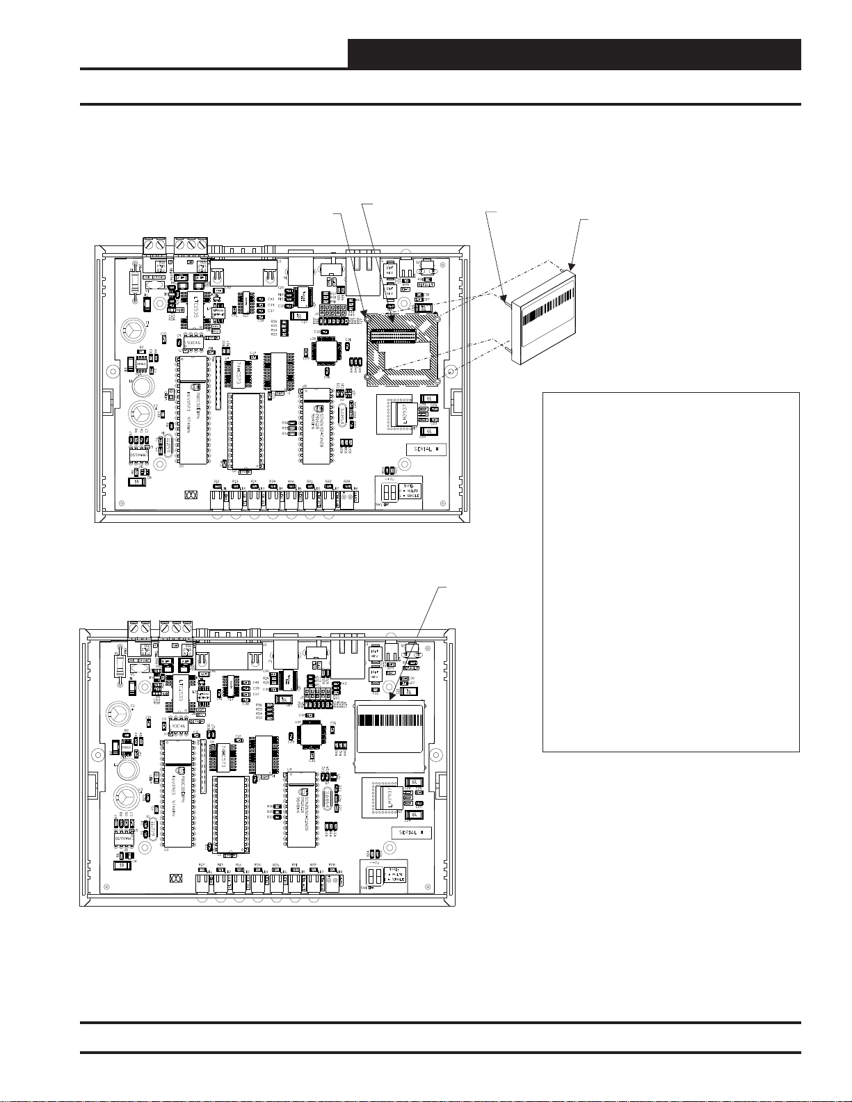
CommLink IV IP Module Installation
Installing the OE415-02 IP Module into the CommLink IV
IP Module
Socket
WattMaster Controls Inc.
COMMLINK IP
YS102074
REV6
MADE IN USA
Round Pin Hole
ALTERA
EPM3032
CommLink IV With OE415-02 IP Module Installed
IP Module
Seated In
Socket
Location
Pin - Typ.
LANTRONIX
00-20-4A-89-6B-EE
WP5001000-01 Rev.A11
Pat. 4972,470 06W21
Made inTaiwan
IP Module (Part Of OE415-02
IP Module Kit). Used When
TCP/IP LAN Or Internet
Communications With The
Control System Is Desired.
WiPort NR
IP Module Installation Instructions:
First Remove The Enclosure Screws That Hold
The Top And Bottom Of The CommLink
Enclosure Together. Remove The Top Half Of
The Enclosure To Access The Circuit Board And
IP Module Socket.
Insert The IP Module’s Guide Pins Into The
Round Pin Holes On The CommLink Circuit
Board As Shown. When The Pins Are Properly
Aligned, Press Down On The IP Module Firmly
To Seat It Into Its Socket.
While The Top Of The Enclosure Is Removed,
Make Sure That The SW1 DIP Switch Is Set
Correctly. See Figure 3.
After Making Sure The IP Module Is Firmly
Seated, Replace The CommLink Cover And
Secure The Enclosure Halves Back Together
With The Enclosure Screws That Were
Previously Removed.
WiPort NR
LANTRONIX
00-20-4A-89-6B-EE
WP5001000-01 Rev.A11
Pat. 4972,470 06W21
Made in Taiwan
WattMaster Controls Inc.
COMMLINK IP
YS102074
REV6
MADE IN USA
ALTERA
EPM3032
Figure 1: Installing the IP Module into the CommLink IV
Technical Guide
Follow The Instructions In This Guide For
Installing The IP Module Software And
Configuring The IP Module For Your Control
System.
5
Page 6
IP MODULE
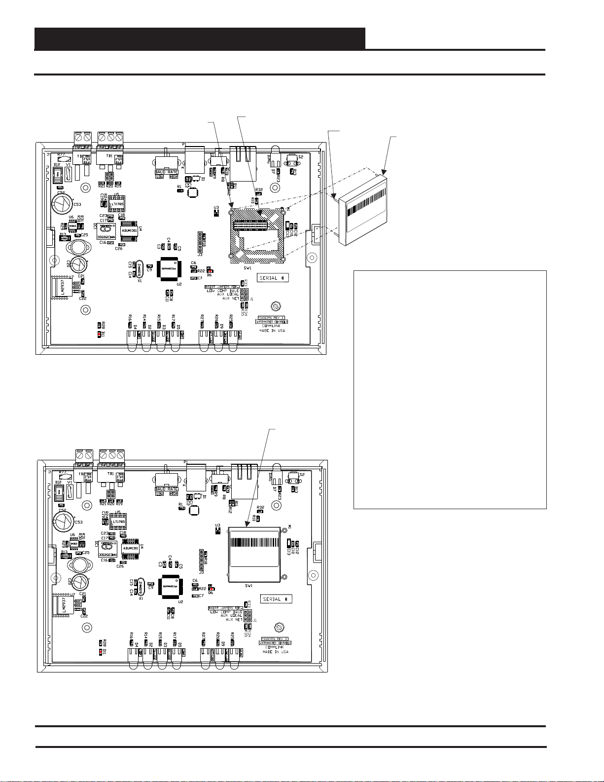
CommLink 5 IP Module Installation
Installing the OE415-02 IP Module into the CommLink 5
Round Pin Hole
R
GND
GND
24VAC
24VAC
R
SH
SH
T
T
PIC
PIC
32
32
IP Module
Socket
Location
Pin - Typ.
IP Module (Part Of OE415-02
IP Module Kit). Used When
TCP/IP LAN Or Internet
Communications With The
Control System Is Desired.
WiPort NR
LANTRONIX
00-20-4A-89-6B-EE
WP5001000-01 Rev.A11
Pat. 4972,470 06W21
Made inTaiwan
IP Module Installation Instructions:
First Remove The Enclosure Screws That Hold
The Top And Bottom Of The CommLink
Enclosure Together. Remove The Top Half Of
The Enclosure To Access The Circuit Board And
IP Module Socket.
CommLink 5 with OE415-02 IP Module Installed
IP Module
Seated In
Socket
R
GND
GND
24VAC
24VAC
R
SH
SH
T
T
WiPort NR
LANTRONIX
00-20-4A-89-6B-EE
WP5001000-01 Rev.A11
Pat. 4972,470 06W21
Made in Taiwan
PIC
PIC
32
32
Insert The IP Module’s Guide Pins Into The
Round Pin Holes On The CommLink Circuit
Board As Shown. When The Pins Are Properly
Aligned, Press Down On The IP Module Firmly
To Seat It Into Its Socket.
After Making Sure The IP Module Is Firmly
Seated, Replace The CommLink Cover And
Secure The Enclosure Halves Back Together
With The Enclosure Screws That Were
Previously Removed.
Follow The Instructions In This Guide For
Installing The IP Module Software And
Configuring The IP Module For Your Control
System.
Figure 2: Installing the IP Module into the CommLink 5
6
Technical Guide
Page 7

IP MODULE
CommLink IV Communications Setting
Setting the CommLink IV Communications Setting
WiPort NR
LANTRONIX
00-20-4A-89-6B-EE
ALTERA
EPM3032
WP5001000-01 Rev.A11
Pat. 4972,470 06W21
Made inTaiwan
CommLink IV Communications Setting
The SW1 DIP Switch Located On The Circuit Board
Inside The CommLink IV Housing Must Be Set
Correctly For Your Specific Application In Order To
Function Properly.
For Multiple Loop Applications.
The CommLink IV Is Factory Set
WattMaster Controls Inc.
COMMLINK IV
YS102074
REV6
MADE IN USA
DIP Switch 1 On & 2 Off =
Single Loop Communications
To Check And/Or Set The SW1 Dip Switch, First
Remove The (2) Enclosure Screws That Hold The
Top And Bottom Of The CommLink IV Enclosure
Together. Remove The Top Half Of The Enclosure To
Access The Circuit Board And Dip Switches.
The DIP Switch Setting Be Set To
SW1 Must
“Multiple”
In The Following Situation:
When There Is A MiniLink Wired To Your System.
The SW1 DIP Switch Setting Must Be Set To “Single”
In The Following Situation:
When There IS NO MiniLink Wired To Your
System.
Replace The CommLink IV Cover And Secure The
Enclosure Halves Back Together With The (2)
Enclosure Screws That Were Previously Removed.
DIP Switch 1 & 2 Off =
Multiple Loop Communications
Figure 3: CommLink IV Communication Settings
Technical Guide
7
Page 8

IP MODULE
CommLink 5 Communications Setting
Setting the CommLink 5 SettingCommunications
Back of CommLink 5
MULTIPLE
SINGLE
MULTIPLE
HIGH
LOW
BAUDLOOP
SINGLE
LOOP
Switch Set To Multiple
Loop Communications
SERIAL #
SHLD
GND
T(-)
24V
R (+)
CommLink 5 Communications Setting
The Loop Switch Located On The Back Of The
CommLink 5 Housing Must Be Set Correctly For
Your Specific Application In Order For The
CommLink 5 To Function Properly.
The CommLink
5 Is Factory Set For Multiple Loop Applications.
The Switch Setting Should Be Set To
Loop
“Multiple” In The Following Situation:
You Have A Single CommLink With
MiniLink(s) or MiniLink PD(s) Installed On
Your System.
The Loop Switch Setting Should Be Set To
“Single” In The Following Situation:
You Have A Single CommLink Without Any
MiniLinks Or MiniLink PDs Installed On Your
System.
MULTIPLE
SINGLE
LOOP
Switch Set To Single
Loop Communications
Figure 4: Setting Loop Communications
8
Technical Guide
Page 9

Setting the CommLink 5 Baud Rate
Back of CommLink 5
MULTIPLE
SINGLE
HIGH
HIGH
BAUDLOOP
LOW
LOW
BAUD
IP MODULE
CommLink 5 Baud Rate Setting
SERIAL #
SHLD
GND
T(-)
24V
R (+)
CommLink 5 Baud Rate Setting
The Baud Rate Switch Located On The Back Of
The CommLink 5 Housing Must Be Set Correctly
For Your Specific Application In Order For The
CommLink 5 To Function At Maximum Efficiency.
The CommLink 5 Is Factory Set For Low Baud
Rate Applications.
The Should Be Set To “High” In The
Baud Rate
Following Situations:
You Are Using Only 2 Controllers, Only
GPC-XP Controllers, or Only VCB-X
Controllers On Your System.
AZ
Switch Set To High Baud
Rate (115,200)
HIGH
LOW
BAUD
Switch Set To Low Baud
Rate (Anything Less Than
115,200)
The Baud Rate Should Be Set To “Low” In The
Following Situations:
You Are Using Orion Controllers Or Are
Using Orion Controllers In Combination
With VCB-X or GPC-XP Controllers. For
Example, VCB-X or GPC-XP Controllers
With VCM-X or VCM Controllers.
Figure 5: Setting the Baud Rate
Technical Guide
9
Page 10

IP MODULE
CommLink IV with IP Module Connections and Wiring
CommLink IV with IP Module Connection & Wiring
WARNING! Do Not Have Your Ethernet Connection
And USB Connection Connected At The Same Time.
This Could Cause Unreliable Communications.
CommLink IV with IP Module
Reset
Default
Values
When Connecting Directly To Your
Computer, Use The 10
Crossover
Long CAT5 Ethernet Cable
(Included).
Prefabricated Ft.
Supplied With CommLink
But Not Required For IP
Module Installation. See
Note 2.
Connect Directly To Your Computer
(Crossover CAT 5) Or Connect To An
Available 10/100 BaseT Port On Your
LAN (Standard CAT 5).
DIAG
10/100
ETHERNET
ACT LNK
USB
Config
Normal
COMPUTER
USB
MODEM
RS-232
TGR
485 LOOP
24V
POWER
Serial #
GND
24 VAC Power
18 Gauge 2 Conductor
With Shield (Not Included)
See Note 1.
Connect To A
MiniLink PD, MiniLink
Or Other Controller As
Required By Your
Specific System
Wiring Instructions.
See Note 1.
120 to 24 VAC Power Pack
(Included With CommLink IV)
Connect To 120/1/60 Duplex
Receptacle (By Others).
If Desired A 24 VAC Transformer
(Not Included) Rated At 12 VA
Minimum May Be Used Instead
Of The Supplied Power Pack.
Use 18 Gauge Minimum
2 Conductor Wire Between The
Transformer & CommLink IV
Terminals.
NOTES:
1.) Use 18 Gauge Minimum 2 Conductor Twisted Pair With Shield Cable Belden #82760
(Not Included) Or Equivalent To Connect The CommLink IV To A MiniLink Or MiniLink PD
On The Network Loop Or To Controllers On A Local Loop.
2.) The CommLink IV Cannot Communicate With The Control System Through Its
Ethernet Port And USB Port At The Same Time.
3.) All Wiring Must Conform To Applicable Federal, State & Local Electrical Wiring Codes.
Figure 6: CommLink IV with IP Module Connection & Wiring
10
Technical Guide
Page 11

IP MODULE
CommLink 5 with IP Module Connections and Wiring
CommLink 5 with IP Module Connections & Wiring
WARNING! Do Not Have Your Ethernet
Connection And USB Connection
Connected At The Same Time. This
Could Cause Unreliable Communications.
DIAG
USB Cable (Included).
Connect This Cable To
Your Computer USB Port
For Direct Connection To
The CommLink 5. Also
Used For Advanced
Configuration of The
CommLink 5.
Optional - Prefabricated Ft. Long CAT5
Ethernet Cable (Included With Optional OE41502 IP Module Kit).
Ethernet Router On Your LAN.
Ethernet Cable Is Required, You Will Need To
Obtain (From Others) And Install An Ethernet
Cable Of The Required Length For Your
Installation.
10
Connect To A 10/100 Base-T
10/100
ETHERNET
ACT LNK
If A Longer
When Using
A MiniLink,
Switch Should
Be Set To
Multiple.
COMPUTER
USB
MULTIPLE
SINGLE
LOOP
BAUD
HIGH
LOW
CommLink 5
with IP Module
SHLD
T(-)
R(+)
485 LOOP
POWER
NOTE: Please Note, The R(+) And T(-)
Terminals On The Communications Terminal
Block Are Reversed From All Previous
Versions Of The CommLink.
WARNING! If You Are Replacing An Earlier
Version Of The CommLink With A CommLink 5,
Be Aware That The Polarity Of The Terminal
Block Is Reversed On The CommLink 5 From
All Previous Models. You Must Always Confirm
That The Polarity Is Correct When Wiring 24 VAC
Power To The CommLink Power Terminal Block
Or Serious Damage To The Product Will Result.
GND
Serial #
24V
24 VAC Power
18 Gauge 2 Conductor
With Shield (Not Included)
See Note 1.
Connect To A
MiniLink PD, MiniLink
Or Other Controller As
Required By Your
Specific System
Wiring Instructions.
See Note 1.
120 to 24 VAC Power Pack
(Included) Connect To 120/1/60
Duplex Receptacle (By Others).
If Desired A 24 VAC Transformer
Included)
Used Instead Of The Supplied Power Pack.
Use 18 Gauge Minimum 2 Conductor Wire
Between The Transformer & CommLink 5
Terminals.
Rated At 12 VA Minimum May Be
(Not
NOTES:
1) Use 18 Gauge Minimum 2 Conductor Twisted Pair With Shield Cable Belden #82760 Or Equivalent (Not Included) To Connect
The CommLink 5 To A MiniLink Or MiniLink PD.
2) For Direct Connection Via USB, Your Computer Must Have An Unused USB Port Available. Drivers For Your USB Port Are
Provided On A CD Supplied With The CommLink 5. Please Follow The Directions In The CommLink 5 USB Driver Installation
Section (Included) To Install And Configure The USB Drivers.
3) The CommLink 5 Cannot Communicate With The Control System Through Its Ethernet Port And USB Port At The Same Time.
4) All Wiring Must Conform To Applicable Federal, State & Local Electrical Wiring Codes.
Figure 7: CommLink 5 Connection & Wiring
Technical Guide
11
Page 12

IP MODULE
CommLink with IP Module Hardware Connection
CommLink with IP Module
Hardware Connection
You have two options for connecting the CommLink to your PC
via Ethernet:
1.) You can connect the CommLink directly to your PC
by using a crossover CAT 5 Ethernet cable (provided) as
shown. See Figure 8 for details.
2.) You can connect both your PC and the CommLink to
an Ethernet Hub with standard CAT5 cables (by others).
See Figure 9 for details.
4
3
2
1
Figure 8: Connecting with Crossover Ethernet
Cable (CommLink IV shown)
Figure 9: Connecting with Ethernet Cable and Hub
(CommLink IV shown)
If using a hub or switch, connect a standard CAT 5 cable from the
CommLink to the hub or switch. You will also need to connect
your computer to the LAN via standard CAT 5 (by others).
If connecting directly to the CommLink without a hub or switch,
use a crossover CAT 5 Ethernet cable. The LNK-LAN LED will
light up once power is applied, indicating connection to the LAN.
Power up the CommLink by plugging in the power cable. The
CommLink may take up to three minutes to power up completely.
Once the CommLink is powered up, you should notice that the red
“LOOP” LED light on the CommLink remains lit continuously
and fl ickers during communication. See Figures 18 & 19, pages
17 & 18 for the LED location.
12
Technical Guide
Page 13

IP MODULE
CommLink Confi guration
Computer IP Address Set-up for
Windows® XP, Vista, 7, or 8
In order for the CommLink to communicate properly, you must
set the IP address of the CommLink and computer to be within
the same netmask. The following instructions explain how to
change your computer’s IP address.
1.) Click <start>; then click <Control Panel>.
2.) Double-click <Network Connections> (XP), <Net-
work & Sharing Center> (Vista), or <Network & Internet>
(7), The Network Connections Window or Network
& Sharing Center Window will appear (XP or Vista). Windows 7 & 8 users, click <Network and Sharing Center>
for the
Network & Sharing Center Window.
4.) Click the <Properties> button. The Local Area Con-
nection Properties Window will appear.
Figure 12: Local Area Connection Properties
Window
5). In the Connection Items List Box, be sure the Internet
Protocol (TCP/IP) is checked (Figure 12). (In Vista, this
will be TCP/IP v.4.) Click Internet Protocol (TCP/IP v.4)
to highlight it and then click
<Properties>. The Internet
Protocol Properties Window will appear.
Figure 10: Network Connections Window
NOTE: If any wireless connections are listed, disable
them by right-clicking the connection and
selecting
<Disable>.
3.) In the Network Connections Window, select the
Local Area Connections entry. (In Vista, fi nd the left
panel and click on Manage Network Connections.) The
Local Area Connection Status Window will appear.
Figure 11: Local Area Connection Status Window
Figure 13: Internet Protocol Properties Window
6). Type in the following information:
a.) Make the IP address 192.168.1.5
b.) Make the Subnet mask 255.255.255.0
c.) Blank out the Default gateway setting (leave
the setting blank as shown in Figure 13).
d.) Blank out the Preferred DNS server setting and
the Alternate DNS server setting (see Figure 13).
7.) Select
<OK> until all of the above windows are
closed. You may have to reboot the computer before the
new values are valid.
Technical Guide
13
Page 14

IP MODULE
CommLink Confi guration
Changing the IP Address of the
CommLink
Follow the instructions below to set your IP Module’s IP address.
Be sure you have confi gured your PC’s IP address as described
on page 13.
1.) Run the Prism 2 program, open the Job Sites Window,
and type the default IP address 192.168.1.25 in the Node
IP Addr ess fi eld. See the Prism 2 Technical Guide if
needed for further instructions. To access the IP Module
web page, click on the
click
<CommLink IP Web Settings> (see below).
The IP Module web page should appear as shown in
Figure 14.
<Communications> tab and then
3.) Click
bar on the left side of the web page.
Figure 15: CommLink’s IP Module Network
Confi guration Settings
4.) Under IP confi guration, select the radio button
in front of the option
confi guration> and type in the IP address,
Subnet Mask, and Default Gateway as provided
by the jobsite IT staff.
<Network Confi guration> found in the menu
<Use the following IP
Figure 14: CommLink’s IP Module Home Page
2.) Enter a password if required. By default, the
CommLink does not have a user name or password.
14
NOTE: Be sure all other settings are set to default as shown
in Figure 15.
5.) Click <OK> at the bottom of the Network Settings
Screen once the changes have been made.
Technical Guide
Page 15

IP MODULE
CommLink Confi guration
6.) Click <CommLink Confi guration> found in the menu
bar on the left side of the web page.
7.) Under Port Settings, in the Baud Rate drop down
menu, select 19,200 as the baud rate for the CommLink IV
or 115,200 if using a CommLink 5.
Figure 16: CommLink Baud Rate Setting
9.) After you are done modifying the IP settings, click
<Apply Settings> in the menu bar to the left.
10). The following message will appear on the screen
and the LNK-LAN LED will blink once:
11.) When the LNK-LAN LED fl ashes, it indicates that
the new settings have been saved. To verify that the
changes were successful, fi rst connect the IP Module to
the building’s network using a standard Ethernet cable.
Then make sure your PC has a connection to the Local
Area Network and reopen the IP Module Setup Webpage
by typing in the newly assigned IP Address.
8.) Click
Screen once the changes have been made.
<OK> at the bottom of the Serial Settings
12.) Be sure to set the IP address in Prism 2 to the new IP
address set up for the CommLink.
Technical Guide
15
Page 16

IP MODULE
Connecting the Network
Proxy and Firewall Compatibility
Proxy and Firewall confi gurations may become necessary
when the CommLink is connected to a LAN/WAN that is
protected by a commercially available Firewall, Proxy, or NAT
enabled router. Examples of these would include Cisco, NetGear,
LinkSys, or WatchGuard Technologies. Also, some ISPs provide
IP Address ranges that are already fi re-walled at the NOC or ISP
Head-End. Make sure that your IT Department or ISP can create
a mapped TCP port 39288 on your fi rewall/proxy to TCP port
39288 on the assigned IP Address of the CommLink.
Ethernet Cable To Other
Nodes On Building LAN Or WAN
Firewall //Proxy Router
Ethernet Cable
Only with proper configuration of the Firewall/Proxy are
connections to the CommLink from outside of the local area
network going to be possible. Check that the Firewall/Proxy port
is not set to time out or reset after a specifi ed amount of time
when there is no traffi c from the remote PC.
Personal Computer
Optional Direct
Computer Connection
To CommLink 5 Via Crossover
(Supplied with IP Module)
CommLink 5
Figure 17: Example Network Diagram of a Firewall or Proxy Confi guration
16
Technical Guide
Page 17

CommLink IV
IP MODULE
CommLink IV LED Descriptions
LOOP
TX-USB
RX-USB
STATUS
www.wattmaster.com
Figure 18: CommLink IV LED Display
CommLink IV LED Descriptions
LOOP - Indicates communication activity on local controller
network. This LED fl ickers off when data is exchanged with
controller network.
TX-USB - Indicates transmitted data status of USB
connection. This LED only fl ashes if the CommLink IV is
directly connected to a computer via a USB port. It will not
fl ash when using the IP Module for LAN or WAN
connections.
TX-CPU
TX-CPU - Indicates transmitted data status. This LED
RX-CPU - Indicates received data status. This LED fl ashes
ACT-LAN - Indicates activity on the local area network.
ACT-LAN
RX-CPU
fl ashes when data is sent to Prism 2 from the CommLink
IV using USB or Ethernet.
when data is sent from Prism 2 to the CommLink IV using
USB or Ethernet.
This LED fl ashes on when LAN is transmitting and
receiving data and only fl ashes if the IP Module is
installed and operating.
LNK-LAN
CONTROLS
RX-USB - Indicates received data status of USB connection.
This LED only fl ashes if the CommLink IV is directly
connected to a computer via a USB port. It will not fl ash
when using the IP Module for LAN or WAN connections.
Technical Guide
LNK-LAN - Indicates local area network is connected. This
LED is on when connected to LAN and only fl ashes if the
IP Module is installed and operating.
17
Page 18

IP MODULE
CommLink 5 LED Descriptions
Figure 19: CommLink 5 LED Display
CommLink 5 LED Descriptions
USB LEDs
LOOP - Indicates communication activity on local controller
network. This LED fl ickers when data is exchanged with
the controller network.
TX-USB - Indicates transmitted data status of USB
connection. This LED only fl ashes when your CommLink 5
is connected to a computer and data is sent to Prism 2 from
the CommLink 5 via USB.
RX-USB - Indicates received data status of USB connection.
This LED only fl ashes when your CommLink 5 is
connected to a computer and data is sent from Prism 2 to
the CommLink 5 via USB.
COMP- Indicates connection to your computer. This LED
will turn on solid once you plug the USB cable into your
computer as long as the connection is not lost.
NETWORK LEDs
ACT-LAN - Indicates activity on the local area network. This
LED fl ashes on when LAN is transmitting and receiving
data and is only operational with an Ethernet connection.
LNK-LAN - Indicates local area network is connected. This
LED is on when connected to LAN and is only operational
with an Ethernet connection.
WLAN - Indicates wireless connection to the local area
network. This LED fl ashes on when LAN is transmitting
and receiving data and is only operational with an Ethernet
connection.
18
Technical Guide
Page 19

IP MODULE
Troubleshooting
Troubleshooting Procedures
Ethernet Connection When the device is connected to a
hub, verify that the LINK LED is lit on the CommLink device
and the ACT LED occasionally blinks. The ACT LED indicates
network activity and may be refl ecting other network traffi c.
Ethernet Connection, Routing Verify the route is available
to the CommLink and fi rewalls or proxies are confi gured to pass
TCP network traffi c on port 39288 if necessary. This can be
verifi ed by your Network Administrator.
IP Address Verify that the assigned IP Address is valid for the
local network and that it is not in use by any other device. Try
to PING the CommLink’s IP address to confi rm the address is
correct and responding.
NOTE: Make sure that the CommLink is connected as
shown in Figures 6 or 7 and all installation pro-
cedures have been completed prior to using the
“ping” command.
Prism 2 Software Verify that the IP address is correctly
entered in the connection profi le for the CommLink. Also verify
that the port is left blank in the profi le. This port area specifi es
Comm port settings, not an IP address port.
TCP Port Address The TCP port address 39288 is hard coded
into the EPROM of the CommLink and in Prism 2 software. It
cannot be changed by the end user. The TCP port address needs
to be set in your Prism 2 connection.
NOTE: WattMaster Controls Technical Support cannot
troubleshoot internal PC and/or Windows®-based
operating system problems.
NOTE: WattMaster Controls Technical Support cannot
troubleshoot fi rewalls, routers, and/or problems
on a customer’s internal or external network. An
IT professional may need to be consulted.
To do this, open a DOS session by opening a command prompt:
1. To open a command prompt, click
to <All Programs>, point to <Accessories>,
and then click
2. PING to the IP Address by typing:
ping IP address
Example: ping 192.168.1.25
3. Press <Enter> on the keyboard.
4. If no reply is received, fi rst check your PC’s IP
address and Ethernet connections. If problems
persist, consult your network administrator.
<Command Prompt>.
<Start>, point
Technical Guide
19
Page 20

Form: WM-IPM-TGD-01N Printed in the USA March 2015
All rights reserved. Copyright 2015
WattMaster Controls, Inc. 8500 NW River Park Drive Parkville, MO 64152
Phone (816) 505-1100 www.wattmaster.com Fax (816) 505-1101
 Loading...