

EZ ZoneEZ Zone
EZ Zone
EZ ZoneEZ Zone
+
FAN
COOL 1
COOL 2
HEAT1
HEAT2
BYPASSOPEN
MODE
FRI
M
+
+
COOL
YORK
03:48P
OCCUPIED
Meridian
ALARMS
4-08-96
NO
0
2
1
5
4
8
7
0
*
BYPASSCLOSE
COMMUNICATION
ALARM
A = ALL ZONES
B = EACH ZONE
A
C = HVACUNIT/CLEAR
3
B
D = ALARMS
6
C
# = STEP/ENTER
9
= DECIMAL
D
*
#
+
+
COOL
YORK
03:48PM
OCCUPIED
Meridian
ALARMS
NO
04-08-96
2
1
5
4
8
7
0
*
MODE
3
6
9
#
FRI
A
B
C
D
FAN
COOL 1
COOL 2
HEAT1
HEAT2
BYPASSOPEN
BYPASSCLOSE
COMMUNICATION
ALARM
A = ALL ZONES
B = EACH ZONE
C = HVACUNIT/CLEAR
D = ALARMS
# = STEP/ENTER
= DECIMAL
*
+
TT
oo
T
o
TT
oo
+
UpgUpg
Upg
UpgUpg
rr
adeade
r
ade
rr
adeade
+
AA
uto-Zoneuto-Zone
A
uto-Zone
AA
uto-Zoneuto-Zone
Auto-Zone Plus
OCCUPIED
09/20/00 03:38PM WED
NO ALARMS
M
3
2
6
1
5
9
4
7
Dec.
*
C
8
inus
M
0
u
n
e
r
lea
MANAGER
SYSTEM
Esc
Enter
rm
la
A
tio
a
ic
n
u
m
m
o
rrid
C
e
v
O
WATTMASTER CONTROLS INC.
n
e
GuideGuide
Guide
GuideGuide

8500 NW River Park Drive • Parkville , MO 64152
PH: (816) 505-1100 • FX: (816) 505-1101 • E-mail: mail@wattmaster.com
Visit our website at www.wattmaster.com
Form: WM-AEZ-UG-01C Copyright 2000 WattMaster Controls, Inc.
Auto-Zone & System Manager are registered trademarks of WattMaster Controls, Inc.
EZ Zone is a registered trademark of York International Corp.
WattMaster Controls assumes no responsibility for errors, or omissions.
This document is subject to change without notice. All rights reserved.

Table of Contents
Introduction ........................................................................................................................................ 4
EZ Zone Upgrade Overview .............................................................................................................. 5
Component Descriptions .................................................................................................................... 6
Upgrade Package Selection ................................................................................................................ 7
Example #1 - EZ Zone Stand Alone To AZ Basic ..................................................................... 8 & 9
Example #2 - EZ Zone Stand Alone To AZ Plus ................................................................... 10 & 11
Example #3 - Networked EZ Zone To AZ Plus ..................................................................... 12 & 13
Optional Controllers And Accessories................................................................................... 14 & 15
EZ Zone Wiring ................................................................................................................................ 16
Auto-Zone Basic Wiring .................................................................................................................. 17
Auto-Zone Plus Wiring .................................................................................................................... 18
Auto-Zone Plus Address Switches................................................................................................... 19
HVAC Staging Connections ............................................................................................................. 20
Sensor Connections .......................................................................................................................... 21
Bypass Damper Connections ........................................................................................................... 22
Honeywell Economizer Actuators ................................................................................................... 23
System Manager Installation ........................................................................................................... 24
CommLink II Installation ................................................................................................................ 25
Modem Linc Central EPROM Replacement ................................................................................ 26
Master Interface EPROM Replacement ........................................................................................ 27
Zone Controller EPROM Replacement.......................................................................................... 28
EPROM Installation Procedures..................................................................................................... 29
Ribbon Cable Installation ................................................................................................................ 30
Upgrade Parts List Summary .......................................................................................................... 31
Additional Information .................................................................................................................... 32
Table of Figures
Figure 1: Existing EZ Zone Master Controller Wiring ................................................................ 16
Figure 2: New Auto-Zone Basic Controller Wiring ...................................................................... 17
Figure 3: Existing Auto-Zone Plus Controller Wiring .................................................................. 18
Figure 4: New Auto-Zone Plus Address Switch Setting ................................................................ 19
Figure 5: Existing EZ Zone HVAC Wiring .................................................................................... 20
Figure 6: New Auto-Zone HVAC Wiring ....................................................................................... 20
Figure 7: Existing EZ Zone Master Controller Sensor Wiring .................................................... 21
Figure 8: New AZ Zone Manager Sensor Wiring.......................................................................... 21
Figure 9: Existing EZ Zone Bypass Damper Wiring .................................................................... 22
Figure 10: New Auto-Zone Bypass Damper Wiring...................................................................... 22
Figure 11: Honeywell Economizer Actuators Wiring Information.............................................. 23
Figure 12: System Manager Wiring................................................................................................24
Figure 13: CommLink II Wiring ..................................................................................................... 25
Figure 14: EZ Zone Modem Linc Central EPROM Location ...................................................... 26
Figure 15: EZ Zone Master Interface Board EPROM Location ................................................. 27
Figure 16: EZ Zone Zone Controller EPROM Location .............................................................. 28
Figure 17: EPROM Removal & Installation .................................................................................. 29
Figure 18: 3 Connector Ribbon Cable Installation ....................................................................... 30
EZ Zone/Auto-Zone
Introduction
+
YORK
OCCUPIED
Meridian COOL MODE
NO ALARMS
04-08-96 03:48PM FRI
1
4
7
*
The Auto-Zone Controls System was created from the
+
FAN
COOL 1
COOL 2
HEAT1
HEAT2
BYPASSOPEN
BYPASSCLOSE
COMMUNICATION
ALARM
A = ALL ZONES
B = EACH ZONE
A
C=HVACUNIT/CLEAR
3
B
D = ALARMS
2
6
C
# = STEP/ENTER
5
9
= DECIMAL
D
*
8
#
0
+
original EZ Zone Control System concept by redesigning, enhancing and expanding the original systems capabilities under the new Auto-Zone Controls System
name.
WattMaster’s Auto-Zone Control Systems have continued in the York EZ Zone tradition of keeping the controls simple to install and use while enhancing the system to make it more applicable and in line with the needs
of the current marketplace. In addition to offering an
excellent control system for zoning applications, the
Auto-Zone Control System has been expanded to allow control of multiple single zone constant volume
units and other devices such as lighting, exhaust fans,
and unit heaters.
+
The York International Corporation’s EZ Zone Controls
System was first introduced in the early nineties. The
EZ Zone Controls System was designed for York, by
WattMaster Controls, as a simple zone control system
for York’s line of commercial unitary roof top and split
system HVAC units. Since its original design and introduction, the York EZ Zone Control System has
changed very little.
Auto-Zone Plus
OCCUPIED
09/20/00 03:38PM WED
NO ALARMS
3
2
6
1
5
9
4
8
Minus
7
0
Dec.
*
Upgrading your EZ Zone system to the Auto-Zone Controls system allows you and your customer to take advantage of the many improvements that have been made
in the Auto-Zone Controls system without having to
replace all the EZ Zone system components that are
installed on your job.
This guide is intended to provide you with simple
instructions on upgrading an existing EZ Zone system
to an Auto-Zone Control System.
MANAGER
Alarm
Menu
Clear
SYSTEM
Esc
Enter
T
A
W
Communication
R
E
T
S
A
M
T
Override
O
C
.
C
IN
S
L
O
R
T
N
4 Upgrade

EZ Zone Upgrade Overview
EZ Zone/Auto-Zone
The basic steps required to upgrade your EZ
Zone system to an Auto-Zone system are:
z Determine what EZ Zone components
are currently installed on the system.
z Replace the existing EZ-Zone Master
Controller board with an Auto-Zone
Zone Manager controller board
z Replace the existing EZ Zone
EPROM’s in each Zone Controller
with a new Auto-Zone EPROM.
z Install return air and outside air
temperature sensors
EZ Zone to Auto-Zone upgrade allows you to
retain:
z All existing wiring
z Master Controller enclosure with
keypad and display
z Existing supply air and static pressure
sensors
z Existing bypass damper
After upgrading your system from EZ Zone to
Auto-Zone, you will be able to take advantage
of many new enhancements including:
Damper actuators can be programmed
z
for direct or reverse operation
z Full modulating economizer control
capability including optional wetbulb
economizer control
z Outside air temperature sensor provides
lockout function for both heating and
cooling. When converted to Auto-Zone
Plus system only one outside air sensor
is required for the entire system
z Contact closure input for dirty filter
status
z Global and individual zone override
modes
z Zones can be set for voting or
nonvoting status
z Room sensor slide can be programmed
± 0° F to ± 5° F adjustment
from setpoint
z All Zone Dampers
z * All Zone Controllers
z Room sensors
z Staging delays, minimum off times,
and changeover intervals are
programmable
z Sensor offset calibration to correct
sensor errors due to poor location
z * Modem Link Central
z * All Master Interface Boards
z ZoneView enhanced graphical computer
front end software available when
CommLink and a PC are used
z All Fan Terminal Controllers
z System Manager operator interface
* These controllers can be retained but they will re-
quire an EPROM chip upgrade to be compatible
with the Auto-Zone System.
allows all controllers to be accessed from
one central location
Upgrade 5
EZ Zone/Auto-Zone
Component Descriptions
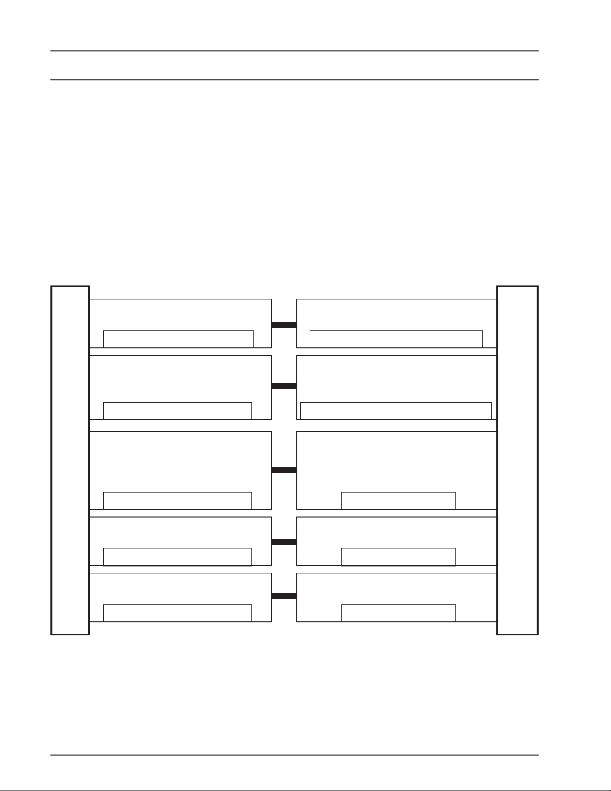
The general architecture of the EZ Zone and the AutoZone Systems are very similar making the upgrade process relatively easy.
There are some changes in the component descriptions
between the EZ Zone system and the Auto-Zone system. It is important to understand these differences
before you begin the upgrade process.
Master Controller Zone Manager
Must Be Replaced Improved Hardware & Software
Fan Terminal
Controller
Many of these components look similar, however, in
some cases they do not function in an identical fashion.
Having the wrong component installed can cause improper system operation.
The chart below depicts the difference in descriptions
for the various comparable system components in the
EZ Zone and Auto-Zone Systems.
Relay Expansion
Board
Replacement Not Required
Master Interface Board
EPROM Replacement Required
EZ Zone Components
Modem Linc Central CommLink II
EPROM Replacement Required
Zone Controller Zone Controller
EPROM Replacement Required
Same As Existing Fan Terminal Controller
MiniLink
Communications
Interface
Improved Software
Auto-Zone Components
Improved Software
Improved Software
6 Upgrade
Upgrade Package Selection
EZ Zone/Auto-Zone
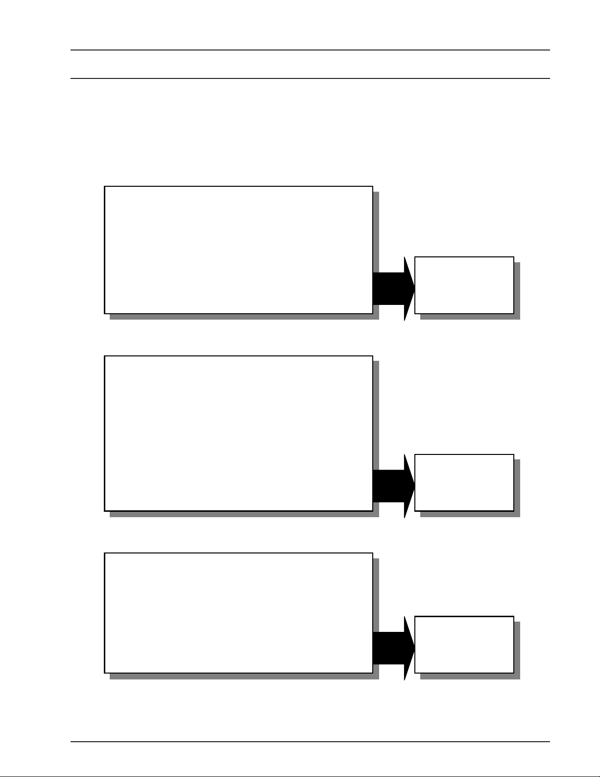
There are basically 3 possible EZ Zone to Auto-Zone
upgrade scenarios you may encounter. We have outlined these below to assist you in deciding which option is best for your application.
Upgrade A Simple EZ Zone Stand Alone
System(s) To The Auto-Zone Basic System
•
Each Existing Master Controller Has It’s Own Display
And Keypad And Is Treated As A Separate System
•
No Communications Cable Between Existing Master
Controllers
•
No Central Display Or Computer Interface Is Desired
Upgrade A Simple EZ Zone Stand Alone
System(s) To The Auto-Zone Plus System
Please see the Auto-Zone upgrade selection chart below to help determine which example best fits your
needs.
See Example #1
On
Pages 8 & 9
•
Two Or More Existing Master Controllers On The Job.
•
No Communications Cable Between Existing Master
Controllers
•
The Customer Wants To Connect The Master
Controllers So That They Are Part Of A Networked
System And/Or Install Constant Volume Unit
Controllers Or Other Controller Boards On Their
System
Upgrade A Networked EZ Zone System To
The Auto-Zone Plus System
•
Two Or More Existing Master Controllers That Are
Networked Together With A Modem Linc Central
•
The Customer May Want To Add Constant Volume
Unit Controllers Or Other Controller Boards To Their
System
See Example #2
On
Pages 10 & 11
See Example #3
On
Pages 12 & 13
Upgrade 7

EZ Zone/Auto-Zone
Example #1:
Your project has a single EZ Zone Master Panel and
it’s associated Zone Controllers. This is a typical EZ
Zone system. The upgrade will essentially convert this
to an Auto-Zone Basic System. Please see the required
upgrade components to be ordered in the list below.
To upgrade your existing EZ Zone System to the AutoZone Basic System the following procedure will be required.
Warning: All removal and installation procedures
must be done with the power to the controllers
turned off. Failure to do so can cause severe damage to the controller boards.
1) All power and input/output wiring will need to be
disconnected from the board. Remove the enclosure
cover and disconnect the keypad & display cable by
unplugging the cable connector at the board connection.
2) The new Return Air Sensor should be installed in
the return air stream in a location upstream of the point
that the bypass duct connects to the return duct.
3) Install the new Outdoor Air Sensor in a location on
the exterior of the building that provides shade and pro-
tection from the weather. See the mounting instructions
included with the sensor for detailed mounting instructions.
4) Remove the existing EZ Zone Master Controller
Board from the EZ Zone enclosure. This will require
the removal of 4 screws securing the board to the enclosure base.
5) Install the new Zone Manager board onto the existing enclosure base. The new board installation requires
6 plastic standoffs be inserted between the back of the
new board and the existing standoffs. Secure the board
to 4 of the threaded standoffs (one in each corner of the
board) with the mounting screws provided.
6) Connect the input, output and power wiring per the
Auto-Zone Basic wiring diagram (See Figure 2 on page
17). Connect the keypad display connector of the existing EZ Zone enclosure cover to the new Auto-Zone Zone
Manager board and secure the existing enclosure cover
to the enclosure base with the existing screws.
7) Remove and replace each EPROM on all the existing EZ-Zone Zone Controllers. See Figures 16 & 17 on
pages 28 & 29 for detailed EPROM Replacement information.
Note: When ordering be sure to specify Fahrenheit or Celsius operation for your system
To Upgrade To The AZ Basic System Order the Following:
(1) (OE751) EZ Zone to Auto-Zone Basic Upgrade Kit
(Includes: Zone Manager Board w/ Mounting Screws, Plastic Standoff Kit for Zone Manager,
Return Air Sensor, Upgrade Label, Installation Instructions.
(1) (OE250) Outside Air Sensor
(X) (OE752) EPROM (Replaces EZ Zone, Zone Controller EPROM) (One Required Per Controller)
For optional components list and information see pages 14 & 15 of this manual.
8 Upgrade
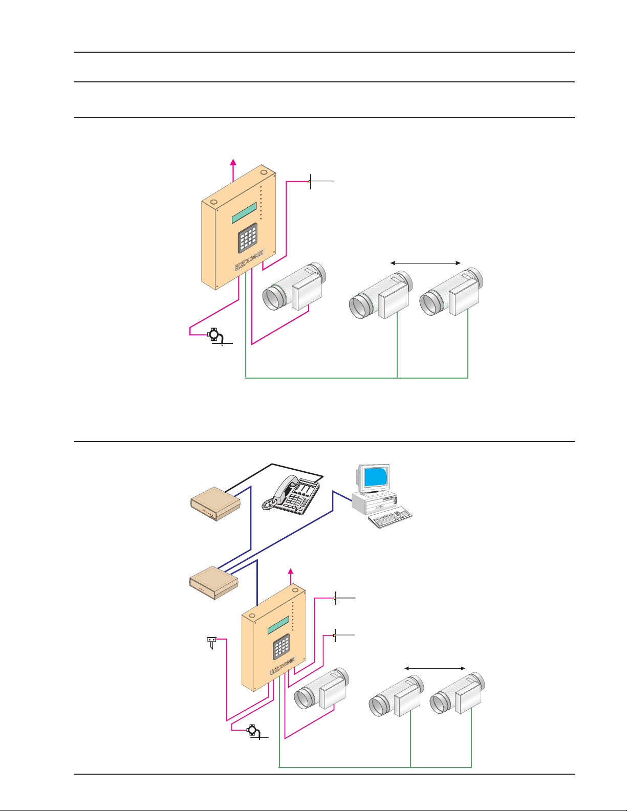
EZ Zone Stand Alone to AZ Basic
COMM
LINK
II
Existing System
To HVAC Unit
Master
Controller
Control Panel
+
YORK
EZ-ZONE COOL MODE
OCCUPIED
NO ALARMS
04-08-96 03:48PM FRI
2
1
5
4
8
7
0
*
+
+
FAN
1
COOL
2
OOL
C
®
HEAT1
2
EN
HEAT
OP
SE
BYPASS
TION
BYPASSCLO
UNICA
MM
CO
ARM
AL
ALLZONES
=
ZONE
A
EACH
=
B
UNIT/CLEAR
AC
=HV
A
C
ARMS
3
AL
=
B
D
6
C
#= STEP/ENTER
9
DECIMAL
=
D
*
#
+
Supply
Air Temp
Sensor
Bypass Air
Damper
Zone Air Dampers
Up to 16 Zone Air Dampers Allowed
#1
EZ Zone/Auto-Zone
#16
Static
Pressure
Sensor
Upgraded System
Telephone Line
(Required For
Remote Link)
1
2
4
3
5
7
6
S
y
c
h
r
o
n
o
u
s
D
a
t
a
L
in
k
SIG
DET
RDY
SND
REC
PWR
C
O
NTR
O
Remote Link
(Optional)
CommLink II
Single Loop
(Optional)
Outside
Air Temp
Sensor
LS
C
O
M
M
L
IN
K
I
I
L
O
C
O
O
M
P
M
O
D
P
E
M
WCLI
AT
T
M
A
S
T
E
R
O
N
T
R
O
S,N
C
Zone Manager
+
8
*
0
To HVAC Unit
Control Panel
FA
O
C
O
C
®
E
H
E
H
Y
E
B
D
I
O
R
M
F
L
M
Y
O
P
B
O
8
C
4
:
D
E
3
YOR K
E
N
0
I
S
O
O
P
M
C
Z
6
U
R
9
C
A
Z
C
L
E
8
O
A
0
A
-
L
O
4
A
N
0
L
A
=
A
A
E
=
B
A
V
H
=
A
C
L
3
A
=
B
D
2
E
6
T
S
1
=
C
#
5
C
9
E
D
4
=
D
*
8
#
7
0
*
9
#
Computer
(Optional - By Others)
Supply
+
N
1
L
O
2
L
O
1
T
A
2
T
A
N
E
P
O
S
S
A
E
P
S
O
L
C
S
N
S
A
IO
P
T
A
IC
N
U
M
M
M
R
S
E
N
O
Z
L
E
N
O
R
Z
A
H
E
L
C
/C
IT
N
U
C
S
M
R
A
R
E
T
N
E
/
P
L
A
M
I
+
Air Temp
Sensor
Return
Air Temp
Sensor
Bypass Air
Damper
Zone Air Dampers
Up to 16 Zone Air Dampers Allowed
#1
#16
+
Static
Pressure
Sensor
Upgrade 9

EZ Zone/Auto-Zone
Example #2:
Your project has multiple EZ Zone Master Panels and
their associated Zone Controllers. This upgrade will
convert this to an Auto-Zone Plus System.
To upgrade your existing EZ Zone System to the AutoZone Plus System the following procedures will be
required.
Warning: All removal and installation procedures
must be done with the power to the controllers
turned off. Failure to do so can cause severe damage to the controller boards.
1) All power and input/output wiring will need to be
disconnected from the existing Master Controller board.
Disconnect the keypad & display cable from the board
by unplugging its connector from the board and the display on the existing enclosure cover.
2) The new Return Air Sensor should be installed in
the return air stream in a location upstream of the point
that the bypass duct connects to the return duct.
3) Install the new Outdoor Air Sensor in a location on
the exterior of the building that provides shade and
protection from the weather. Only one OA sensor is
required for the entire system. See the mounting instructions included with the sensor for detailed mounting
instructions.
4) Connect the CommLink to the network communica-
tions loop and wire in 24VAC power (See Figure 13 on
page 25).
5) Remove the existing EZ Zone Master Controller
Board from the EZ Zone enclosure. This will require
the removal of 4 screws securing the board to the enclosure base.
6) Install the new Zone Manager board onto the existing enclosure base. The MiniLink should then be
mounted to the Zone Manager board using the standoffs and screws included with the MiniLink. The new
Zone Manager board installation requires 6 plastic
standoffs be inserted between the back of the new board
and the existing standoffs. Secure the board to 4 of the
threaded standoffs (one in each corner of the board)
with the screws that were included with the new Zone
Manager board.
7) Connect the input, output and power wiring per the
Auto-Zone Plus wiring diagram (See Figure 3 on page
18). Connect the new 3 Connector Ribbon Cable keypad display connector to the existing EZ Zone enclosure cover and to the new Auto-Zone Zone Manager
board (See Figure 18 on page 30). Secure the existing
enclosure cover to the enclosure base with the existing
screws.
8) Remove and replace each EPROM on all the existing EZ-Zone Zone Controllers. See Figures 16 & 17 on
pages 28 & 29 for detailed EPROM Replacement information.
Note: When ordering be sure to specify Fahrenheit or Celsius operation for your system
To Upgrade To The Auto-Zone Plus System Order the Following:
(X) (OE753) EZ Zone to Auto-Zone Plus Upgrade Kit (One Required Per Existing Master Controller)
(Includes: Zone Manager Board w/ Mounting Screws, Plastic Standoff Kit for Zone Manager,
MiniLink w/ Mounting Hardware, Return Air Sensor, 3 Way Display/Keypad Connector cable,
Upgrade Label, Installation Instructions).
(1) (OE361-04-CLMA) CommLink II Kit (Includes: Cables, Power Supply, Installation Instructions)
(1) (OE250) Outside Air Sensor (Only One Required For Entire System)
(X) (OE752) EPROM (Replaces EZ Zone, Zone Controller EPROM) (One Required Per Controller)
(1) (OE392-01-AZSYSM) System Manager (Not Required if Using Optional Computer)
For optional components list and information see pages 14 & 15 of this manual.
10 Upgrade
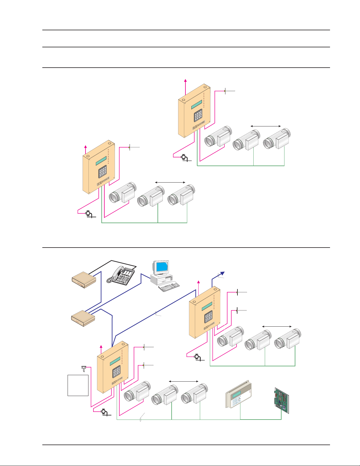
EZ Zone Stand Alone to AZ Plus
C
COMM
LINK
II
MANAGER
Existing System
To HVA
Unit
To HVAC Unit
Control Panel
+
+
YOR K
EZ-ZONE
OCCUPIED
NO
04-08-96
1
4
7
*
Controller
®
FRI
COOL MODE
03:48PM
ALARMS
A
3
B
2
6
C
5
9
D
8
#
0
Master
N
FA
1
L
O
O
C
2
L
O
O
C
1
T
A
E
H
2
T
A
N
E
E
H
P
O
S
S
A
E
P
S
Y
O
B
L
C
S
S
O
A
I
P
T
Y
A
B
C
I
N
U
M
M
O
C
M
R
A
L
S
A
E
N
O
Z
L
L
E
A
N
=
O
Z
A
H
E
L
C
C
A
/
E
T
I
=
N
B
U
C
A
V
H
=
S
C
M
R
A
L
R
A
E
T
=
N
D
E
/
P
E
T
S
=
L
A
#
IM
C
E
D
=
*
Control Panel
Supply
+
N
R
A
+
Air Temp
Sensor
Bypass Air
Damper
Static
Pressure
Zone Air Dampers
Up to 16 Zone Air Dampers Allowed
#1
Sensor
+
+
#16
YOR K
EZ-ZONE
OCCUPIED
NO
04-08-96
1
4
7
*
Master
Controller
®
MODE
FRI
COOL
03:48PM
ALARMS
A
3
B
2
6
C
5
9
D
8
#
0
Supply
+
N
FA
1
L
O
O
C
2
L
O
O
C
1
T
A
E
H
2
T
A
N
E
E
H
P
O
S
S
A
E
P
S
Y
O
B
L
C
S
N
S
A
IO
P
T
Y
A
B
IC
N
U
M
M
O
C
M
R
A
L
S
A
E
N
O
Z
L
L
E
A
N
=
O
R
Z
A
A
H
E
L
C
C
A
/
E
IT
=
N
B
U
C
A
V
H
=
S
C
M
R
A
L
R
A
E
T
=
N
D
/E
P
E
T
S
=
L
A
#
IM
C
E
D
=
*
+
Air Temp
Sensor
Bypass Air
Damper
EZ Zone/Auto-Zone
Zone Air Dampers
Up to 16 Zone Air Dampers Allowed
#1
#16
Static
Pressure
Sensor
Upgraded System
Telephone Line
(Required For Remote Link)
To Other Zone Managers
1
2
4
3
5
7
6
S
y
c
h
r
o
n
o
u
s
D
a
t
a
L
i
n
k
SIG
DET
RDY
SND
REC
PWR
CO
N
TR
O
L
S
Remote Link
(Optional)
8
9
*
0
#
Computer
(Optional - By Others)
Supply
Air Temp
Sensor
Return
Air Temp
Sensor
Network Loop
Zone Air Dampers
Up to 16 Zone Air Dampers Allowed
#1
C
O
M
M
L
I
N
K
I
I
L
O
C
O
O
M
P
M
O
D
P
E
M
WCLI
AT
T
M
A
S
T
E
R
O
N
T
R
O
S,N
C
CommLink II
Multiple Loop
To HVAC Unit
Control Panel
Zone Manager
Outside
Air Temp
Sensor
Only One OA
Sensor Is
Required
For Entire
System
+
+
YOR K
OCCUPIED
Meridian
ALARMS
NO
04-08-96
1
4
7
*
+
N
FA
1
L
O
O
C
2
L
O
O
C
1
T
A
E
H
2
T
A
N
E
E
H
P
O
S
S
E
A
P
S
Y
O
B
L
C
S
MODE
N
FRI
S
O
A
I
P
T
Y
A
B
IC
COOL
N
U
M
M
03:48PM
O
C
M
R
A
L
S
A
E
N
O
Z
L
L
E
A
N
=
O
R
Z
A
A
H
E
L
C
A
/C
E
IT
=
N
B
U
C
A
V
H
=
S
A
C
M
R
A
L
3
R
A
E
T
=
B
N
D
2
/E
P
E
6
T
S
=
L
C
A
#
5
M
I
C
9
E
D
=
D
*
8
#
0
Bypass Air
+
Damper
To HVAC Unit
Control Panel
Zone Manager
Pressure
Sensor
+
+
Static
YOR K
04-
#16
MODE
FRI
COOL
03:48PM
OCCUPIED
Meridian
ALARMS
08-96
NO
A
3
B
2
6
1
C
5
9
4
D
8
#
7
0
*
Local Loop
Static
Pressure
Sensor
(Up to 30 Allowed On System)
Network Loop
Supply
Air Temp
+
N
FA
1
L
O
O
C
2
L
O
O
C
1
T
A
E
H
2
T
A
N
E
E
H
P
O
S
S
E
A
P
S
Y
O
B
L
C
S
N
S
A
IO
P
T
Y
A
B
IC
N
U
M
M
O
C
M
R
A
L
S
A
E
N
O
Z
L
L
E
A
N
=
O
R
Z
A
A
H
E
L
C
A
/C
E
T
I
=
N
B
U
C
A
V
H
=
S
C
M
R
A
L
R
A
E
T
=
N
D
/E
P
E
T
S
=
L
A
#
IM
C
E
D
=
*
+
(Optional If Computer Front End Used)
Sensor
Return
Air Temp
Sensor
Bypass Air
Damper
System
Manager
s
lu
ED
P
SYSTEM
W
e
n
o
-Z
S
uto
A
RM
LA
OCCUPIED
01/01/9703:38PM
NOA
c
s
E
u
en
M
3
2
6
1
r
e
t
n
E
5
r
9
a
le
4
C
s
8
u
in
M
7
0
.
c
e
D
*
ER
ANAG
M
rm
a
Al
n
tio
a
ic
n
u
m
e
m
d
o
ri
C
er
v
O
Zone Air Dampers
Up to 16 Zone Air Dampers Allowed
#1
Other Controllers
(Optional - Up to 13 On Each Loop))
#16
Upgrade 11

EZ Zone/Auto-Zone
Example #3:
Your project has a Networked EZ Zone System that you
want to convert to the Auto-Zone Plus system. Please
see the required upgrade components list below for the
necessary parts to be ordered.
To upgrade your existing Networked EZ Zone System
to the Auto-Zone Plus System the following procedures
will be required.
Warning: All removal and installation procedures
must be done with the power to the controllers
turned off. Failure to do so can cause severe damage to the controller boards.
1) All power and input/output wiring will need to be
disconnected from the existing Master Controller board.
Disconnect the keypad & display cable from the board
by unplugging its connector from the board.
2) The new Return Air Sensor should be installed in
the return air stream in a location upstream of the point
that the bypass duct connects to the return duct.
3) Install the new Outdoor Air Sensor in a location on
the exterior of the building that provides shade and
protection from the weather. Only one OA sensor is
required for the entire system. See the mounting instructions included with the sensor for detailed mounting
instructions.
& 27 for detailed EPROM installation instructions.
5) Remove the existing EZ Zone Master Controller
Board from the EZ Zone enclosure. This will require
the removal of 4 screws securing the board to the enclosure base. Remove the existing Master Interface
Board from the old Master Controller board. Remove
the old EPROM from the Master Interface board and
install the new MiniLink upgrade EPROM to the Master Interface board. See Figures 15 & 17 on pages 26 &
27 for detailed EPROM installation instructions.
6) Install the upgraded Master Interface board to the
new Zone Manager board using the existing mounting
hardware. Install the new Zone Manager board onto the
existing enclosure base. The new Zone Manager board
installation requires 6 plastic standoffs be inserted between the back of the new board and the existing standoffs. Secure the board to 4 of the threaded standoffs
(one in each corner of the board) with the screws that
were included with the new Zone Manager board.
7) Connect the input, output and power wiring per the
Auto-Zone Plus wiring diagram (See Figure 3 on page
18). Connect the existing 3 Connector Ribbon Cable
keypad display connector to the existing EZ Zone enclosure cover and to the new Auto-Zone Zone Manager
board (See Figure 18 on page 30). Secure the existing
enclosure cover to the enclosure base with the existing
screws.
4) Take the cover off of the Modem Link Central, remove the old EPROM and replace with the new
CommLink EPROM. See Figures 14 & 17 on pages 25
Note: When ordering be sure to specify Fahrenheit or Celsius operation for your system
To Upgrade To The Auto-Zone Plus System Order the Following:
(X) (OE751) EZ Zone to AZ Basic Upgrade Kit (One Required Per Existing Master Controller)
(Includes: Zone Manager Board w/ Mounting Screws, Plastic Standoff Kit for Zone Manager,
Return Air Sensor, Upgrade Label, Installation Instructions)
(1) (OE755) Modem Link Central to CommLink II Upgrade Kit
(Includes: ComLink EPROM Upgrade Chip, Upgrade Label)
(1) (OE754) Master Interface Board to MiniLink Upgrade Kit
(Includes: MiniLink EPROM Upgrade Chip, Upgrade Label)
(1) OE250 Outside Air Sensor (Only One Required Per System)
(X) (OE752) EPROM (Replaces EZ Zone, Zone Controller EPROM) (One Required Per Controller)
(1) (OE392-01-AZSYSM) System Manager (Not Required if Using Optional Computer)
For optional components list and information see pages 14 & 15 of this manual.
8) Remove and replace each EPROM on all the existing EZ-Zone Zone Controllers. See Figures 16 & 17 on
pages 28 & 29 for detailed EPROM Replacement information.
12 Upgrade

Networked EZ Zone To AZ Plus
COMM
LINK
II
Teleph
COMM
LINK
II
Existing System
oneLine
24VAC
Modem
(Optional)
C
O
M
M
L
IN
K
II
L
O
C
O
O
M
P
M
O
D
P
E
M
WCLI
ATT
MA
S
T
E
RON
TR
O
S,N
24VAC
C
Modem Link Central
To HVAC Unit
Control Panel
Master
Controller
Master
Controller
To HVAC Unit
Control Panel
+
YOR K
M
4
0
+
Static
Pressure
Sensor
#16
O
M
L
M
O
P
O
8
C
4
:
D
n
3
E
a
0
I
i
S
P
d
M
6
U
i
R
9
C
r
A
C
e
L
8
O
A
0
O
N
3
2
6
1
5
9
4
8
#
7
0
*
1
2
4
3
5
7
6
8
9
*
0
#
Computer
(Optional)
Network Loop
Supply
Air Temp
+
N
FA
1
L
O
O
C
2
L
O
O
C
1
T
A
E
H
2
T
A
N
E
E
H
P
O
S
S
A
E
P
S
Y
O
E
B
L
D
I
C
O
R
S
M
N
F
S
O
A
I
L
P
M
T
O
Y
A
P
O
B
C
8
I
C
+
4
N
U
:
D
n
YOR K
M
3
E
a
M
0
I
i
S
O
P
d
M
C
6
U
i
R
9
C
r
A
C
e
L
M
8
O
M
A
R
0
A
-
L
O
4
S
A
N
0
E
N
O
Z
L
L
E
A
N
=
O
R
Z
A
A
H
E
L
C
C
A
/
E
T
I
=
N
B
U
C
A
V
H
=
S
A
C
M
R
A
L
3
R
A
E
T
=
B
N
D
E
2
/
P
E
6
T
S
1
=
L
C
#
A
5
M
I
C
9
E
D
4
=
D
*
8
#
7
0
*
+
+
Sensor
Bypass Air
Damper
Zone Air Dampers
Up to 16 Zone Air Dampers Allowed
#1
To Other Master Controllers
(Up to 30 Allowed On System)
Network Loop
+
N
FA
1
L
O
O
C
2
L
O
O
C
1
T
A
E
H
2
T
A
N
E
E
H
P
O
S
S
A
E
P
S
Y
O
E
B
L
D
I
C
R
S
N
F
S
O
A
I
P
T
Y
A
B
C
I
N
U
M
M
O
C
M
R
A
L
S
A
E
N
O
Z
L
L
E
A
N
=
O
R
Z
A
A
H
E
L
C
C
A
/
E
T
I
=
N
B
U
C
A
V
H
=
S
A
C
M
R
A
L
R
A
E
T
=
B
N
D
E
/
P
E
T
S
=
L
C
#
A
M
I
C
E
D
=
D
*
+
Supply
Air Temp
Sensor
Bypass Air
Damper
EZ Zone/Auto-Zone
Zone Air Dampers
Up to 16 Zone Air Dampers Allowed
#1
#16
Static
Pressure
Sensor
Upgraded System
Telephone Line
Local Loop
24VAC
Zone
Manager
To HVAC Unit
Control Panel
+
YOR K
r
e
M
0
4
0
+
Static
Pressure
Sensor
#16
E
D
I
O
R
M
F
L
M
O
P
O
8
C
4
:
D
n
3
E
a
0
I
i
S
P
d
M
6
U
i
R
9
C
A
C
L
8
O
A
O
N
A
B
A
C
3
B
D
2
6
1
C
#
5
9
4
D
*
8
#
7
0
*
1
2
4
3
5
7
6
8
9
*
0
#
Modem
(Optional)
C
O
M
M
L
IN
K
II
L
O
C
O
O
M
P
M
O
D
P
E
M
WCLI
ATTMASTER ON
TRO
S,NC
Upgraded
Modem Link Central
To HVAC Unit
Control Panel
Zone
Manager
Outside
Air Temp
Sensor
Only One OA
Sensor Is
Required
For Entire
System
24VAC
+
N
FA
1
L
O
O
C
2
L
O
O
C
1
T
A
E
H
2
T
A
N
E
E
H
P
O
S
S
E
A
P
S
Y
O
E
B
L
D
I
C
O
R
S
M
N
F
S
A
IO
L
P
M
T
O
Y
A
P
O
B
8
IC
C
+
+
YOR K
a
i
d
6
i
9
r
C
e
8
O
M
0
O
4
N
0
1
4
7
N
4
U
:
D
n
M
3
E
M
0
I
S
O
P
M
C
U
R
C
A
L
M
A
R
A
L
S
A
E
N
O
Z
L
L
E
A
N
=
O
R
Z
A
A
H
E
L
C
A
/C
E
IT
=
N
B
U
C
A
V
H
=
S
A
C
M
R
A
L
3
R
A
E
T
=
B
N
D
2
/E
P
E
6
T
S
=
L
C
A
#
5
M
I
C
9
E
D
=
D
*
8
#
0
*
Bypass Air
+
Damper
Supply
Air Temp
Sensor
Return
Air Temp
Sensor
Computer
(Optional)
Network Loop
Zone Air Dampers
Up to 16 Zone Air Dampers Allowed
#1
Local Loop
Static
Pressure
Sensor
To OtherZone Managers
(Up to 30 Allowed On System)
Network Loop
Supply
Air Temp
+
N
FA
1
L
O
O
C
2
L
O
O
C
1
T
A
E
H
2
T
A
N
E
E
H
P
O
S
S
E
A
P
S
Y
O
B
L
C
S
N
S
A
IO
P
T
Y
A
B
IC
N
U
M
M
O
C
M
R
A
L
S
A
E
N
O
Z
L
L
E
A
N
=
O
R
Z
A
H
E
L
C
A
/C
E
IT
=
N
U
C
A
V
H
=
S
M
R
A
L
R
A
E
T
=
N
/E
P
E
T
S
=
L
A
IM
C
E
D
=
+
(Optional If Computer Front End Used)
Sensor
Return
Air Temp
Sensor
Bypass Air
Damper
System
Manager
s
D
lu
E
P
SYSTEM
W
e
n
M
o
8P
-Z
D
to
IE
3:3
S
u
0
P
A
M
U
7
R
C
/9
A
C
L
O
A
/01
O
01
N
c
s
E
u
n
e
M
3
2
6
1
Enter
5
r
9
a
e
l
4
C
s
8
u
n
i
M
7
0
.
c
e
D
*
MANAGER
m
r
a
l
A
n
o
i
t
a
ic
n
u
m
e
m
d
i
o
r
r
C
e
v
O
Zone Air Dampers
Up to 16 Zone Air Dampers Allowed
#1
Other Controllers
(Optional - Up to 13 On Each Loop))
#16
Upgrade 13

EZ Zone/Auto-Zone
Optional Controllers and Accessories
In addition to the standard Zone Manager and Zone
Controllers, WattMaster offers many other controllers
and accessories to enhance your new Auto-Zone System. Optional Controllers that are available for use with
the Auto-Zone Plus system include the CV, CV-C, GPC,
Optimal Start Scheduler, Lighting Panel Controller and
Wetbulb Module. These controllers are not available
for use with the Auto-Zone Basic System. To utilize
any of the optional controllers you must upgrade your
system to the Auto-Zone Plus configuration. Accesso-
CV Controller
The CV Controller provides control of single zone constant volume rooftop or split system HVAC equipment.
CV controllers have four configurable relay outputs for
heating/cooling staging, a 0-10VDC output for economizer control, on board time clock for scheduling/night
setback functions and built in alarming features.
The CV Controller can be used with the Auto Zone
CV-C Controller
ries that are available for use with either the Auto-Zone
Plus or Basic System include the CommLink II Communications Interface, Remote Link, Room Sensors,
Round Zone Dampers and Rectangular Zone Dampers.
WattMaster also offers Communication Cable that is
color coded and labeled for the network communications loop and local communications loop.
Following are brief descriptions of the optional controllers and accessories that are available.
Plus System only. The CV can be programmed and
monitored from the either the System Manager or from
a personal computer which has the ZoneView Computer front end software installed. Up to 13 CV controllers can be installed on each local communications
loop of your Auto-Zone Plus system.
The CV-C Controller is a field configurable constant
volume unit controller that provides additional features
which are not available with the standard CV controller. CV-C controllers can be configured for applications
requiring CO2/IAQ economizer control, modulating HW
and CW control valves and dehumidification. The CVC relay outputs can be expanded via a plug-in expansion board for use in applications requiring additional
heating/cooling staging control.
GPC Controller
The GPC (General Purpose Controller) is a very versa-
tile controller that can be used for a variety of control
applications that are outside the function of our standard HVAC unit controllers. Each GPC controller has
(5) Universal Inputs that can accept contact closures,
thermistor temperature sensors, or 4-20mA/2-10VDC
signals. The controller has (5) digital outputs for on/off
control and (1) 0-10VDC analog output to modulate a
valve or damper. These inputs and outputs can be configured in a variety of ways using And/Or logic functions, time schedules, setpoints, etc. to perform many
different tasks.
The CV-C Controller can be used with the Auto-Zone
Plus System only. The System Manager cannot be used
to program or monitor the CV-C controller. CV-C controllers require that a personal computer which has the
ZoneView computer front end software installed be used
for all programming and monitoring. Up to 13 CV-C
controllers can be installed on each local communications loop of your Auto-Zone Plus system.
The GPC can be used for many applications including,
but not limited to:
• Control of Unit Heaters
• Control of Boilers
• Control of Exhaust Fans
• Monitoring of Temperature
• Monitoring of Humidity
• Monitoring of Status Contacts
The GPC Controller can be used with the Auto-Zone
Plus System only. The System Manager cannot be used
to program or monitor the GPC controller. GPC controllers require that a personal computer which has the
ZoneView computer front end software installed be used
for all programming and monitoring.
14 Upgrade

Lighting Panel Controller
EZ Zone/Auto-Zone
Adds building lighting control capability to the AutoZone System. The Lighting Panel Controller provides
up to (7) Independent time schedules and light levels
for control of up to (7) lighting circuits. The Lighting
Panel Controller relay outputs can be set for on/off relay or pulsed relay control depending on the lighting
system control contactor requirements. Pushbutton override is available for each lighting circuit by connecting
a momentary pushbutton to the Lighting Panel Controller board.
Optimal Start Scheduler
Provides expanded scheduling capabilities beyond those
incorporated with the standard Auto-Zone controllers.
The Optimal Start Scheduler provides for optimal
Start/Stop and up to (7) independent schedules with 2
Start/Stop events per day and (14) Start/Stop holiday
events per schedule.
Wetbulb Module
Provides wetbulb temperature monitoring for control
of all economizer equipped units on the Auto-Zone
system. The Wetbulb Module includes an Outside Air
Humidity Sensor for measuring outside air relative
humidity and utilizes the installed Outdoor Air Sensor
on the Auto-Zone System to calculate the wetbulb
temperature. This temperature is used by the economizer
control portion of the unit controller to provide accurate
The Lighting Panel Controller can be used with the Auto
Zone Plus System only. The System Manager cannot
be used to program or monitor the Lighting Panel Controller. Light Panel Controllers require that a personal
computer which has the ZoneView computer front end
software installed be used for all programming and
monitoring.
The Optimal Start Scheduler can be used with the Auto
Zone Plus System only. The System Manager cannot
be used to program or monitor the Optimal Start Scheduler Controller. This controller requires that a personal
computer which has the ZoneView computer front end
software installed be used for all programming and
monitoring.
economizer operation. The Wetbulb Module can be used
with the Auto-Zone Basic and Plus Zone Systems. The
Wetbulb Module can be monitored and programmed
from either the System Manager or from a personal
computer which has the ZoneView computer front end
software installed.
Accessories
WattMaster offers a complete line of accessories for
your Auto-Zone system. For part ordering information
and a complete list of accessories please see the AutoZone Product List Pricing manual and the Auto-Zone
• Remote Link - 14,400 baud modem for
remote access to any Auto-Zone system
• CommLink II - Required to connect the
Auto Zone Basic system to a personal
computer
• Round Air Dampers - Air damper with a
Zone Controller and actuator mounted in a
control enclosure. Available in pressure
dependent and pressure independent models.
Available in round duct sizes of 6”, 8”, 10”,
12”, 14” and 16” diameter.
Upgrade 15
Replacement Parts List Pricing Catalogs. Following is
a brief list of some of the accessories that are offered
for the Auto-Zone system.
• Rectangular Air Dampers - Rectangular,
aluminum frame opposed blade dampers.
Available in rectangular duct sizes from 8” x
8” to 24” x 36” in 2” increments of height and
width
• Rectangular Air Damper Kit - Zone
Controller and actuator mounted in a control
enclosure for use with Rectangular Air
Dampers
• ZoneView Computer Front End Software
Free when ordered with an EZ Zone to AutoZone upgrade

EZ Zone/Auto-Zone
EZ Zone Wiring
The wiring diagram below depicts a typical existing
EZ Zone Master Controller wiring. This diagram is
shown for reference only. It’s intent is to show the difference between the EZ Zone system wiring and the
Bypass Air Damper
Actuator
90
75
60
45
Master Controller Board
Auto-Zone system wiring. All wiring should be connected per the specific Auto-Zone system wiring diagrams on the following pages.
Splice As
Required
Red
Blk
Grn
LO HI
Static
Pressure
Sensor
Static
Pick-up
Supply Air
Temp Sensor
Actuator Wiring
Interface
Feedback (BK)
Gnd (WH)
Open (YL)
Close (GR)
R
G
Y1
Y2
W1
HVAC Unit
W2
24VAC Only
Line
Voltage
24VAC
GND
RS-485
Communication cable
to Zone Controllers
Figure 1: Existing EZ Zone Master Controller Wiring
16 Upgrade

Auto-Zone Basic Wiring
EZ Zone/Auto-Zone
Figure 2 below depicts the wiring schematic that should
be used for the Auto-Zone Basic System upgrade as
described in Example 1 on pages 8 and 9 of this manual.
Bypass Air Damper
Actuator
90
75
60
45
24VAC
POWER
TB2
GND
Actuator Wiring
Interface
Feedback (BK)
Gnd (WH)
Open (YL)
Close (GR)
Y1
Y2
W1
HVAC Unit
W2
R
G
+
+
REC
FDBK
GND
OPEN
CLOSE
FAN
COOL1
COOL2
HEAT1
HEAT2
V3
V4
V5
V6
24VAC Only
Line
Voltage
24VAC
GND
See Note 1 &2
Notes:
1.)24 VAC Must Be Connected So
That All Ground Wires Remain
Common.
2.)All Wiring To Be In Accordance With
Local And National Electrical Codes
and Specifications.
NE5090
BYPASS
OPEN
BYPASS
CLOSE
G
FAN
Y1
COOL 1
Y2
COOL 2
W1
HEAT 1
W2
HEAT 2
Address Switch Must Always Be Set
To Address 0 on Zone Manager Board
Splice As
Required
LO HI
Static
Pressure
Sensor
Zone Manager
+
+
32BNET
16
8
As Shown
3.)All Communication Wiring To Be 18
Ga. Minimum, 2 Conductor Twisted
Pair With Shield. Belden #82760 Or
Equivalent.
+
5.11V
ADJUST
Auto-Zone COOL MODE
06/11/95 03:48PM FRI
OCCUPIED
NO ALARM(S)
LCD DISPLAY
&
KEYPAD
1 2 3BA
4 5 6
0*#D
D
D
D
D
D
D
D
D
18
20
22
24
1
19
21
23
7
MADE IN U.S.A.
C1992
RockerDown
SW
1
4
>
ADD
OFF
1
4
2
B
32
8
N
1
6
ET
RS-485
Communications To Zone
Controllers
These Switches Must Be
In The OFF Position
As Shown
RockerDown
>
ADD
OFF
1
2
Be sure to pay strict attention to all warnings and cautions listed on the schematic.
Supply Air Temp.
Sensor
Return Air Temp.
Sensor
Outdoor Air Temp.
Auxiliary Inputs
( Dry Contacts )
Aux3
Aux2
Forced
Filter
Occupied
Alarm
Mode
Warning:
See Figure 11 in this manual for
important wiring instructions
regarding Honeywell
Economizer Actuators
Economizer Actuator
WARNING!
Use Extreme Care When Wiring
Economizer Actuators
Never Connect Or Disconnect
Wiring With Power Applied!
Never Apply Power If The
Gnd ( 1 Com ) Terminal On The
Actuator Is Not Connected.
Belimo Actuator Wiring Shown.
Consult Factory For Other
Models Of Economizer Actuators.
Some Actuators Require Isolation
Transformers In Order To Prevent
Damage To The Controller Board.
Sensor
Aux1
Economizer
Disable
5U
4Y2
3Y1
2+
1 COM
BELIMO
AF24-SR
133 IN-LB
C987
Static
Pick-up
Grn
Red
Blk
SEN
TB12
PRESSURE
SO
R
JA
GND
+5V
SIG
C
K
PJ1
ANALOG
INPUTS
+12V
+
+
SAT
RAT
OAT
AUX1
+
AUX2
AUX3
GND
GND
+
EXHAUST
CONTACTS
N.O.
RIBBON
CABLE
ANALOG
OUTPUTS
A1
A2
G
TB2
EXP
BUSS
P1
R5
C
R6
C
1
+
2
To Relief / Exhaust Fans
COMM
T
75176
SH
RS-485
COMM DRIVER
R
Local Loop
Zone Manager
Address Switch
ADD
1
2
4
8
16
32
B
NET
4.)For Individual Component Wiring See
Specific Component Wiring Diagram.
5.)It Is Recommended That All
Controllers Address Switches Are
Set Before Installation.
Figure 2: New Auto-Zone Basic Controller Wiring
Upgrade 17

EZ Zone/Auto-Zone
Auto-Zone Plus Wiring
Figure 3 below depicts the wiring schematic that should
be used for the Auto-Zone Plus System upgrade as described in Example 2 on pages 10 and 11 of this manual.
This schematic is also used for wiring of Example 3 on
Bypass Air Damper
Actuator
90
75
60
45
Actuator Wiring
Interface
Network Loop RS-485
19200 Baud
To Other Zone
Managers and/or
CommLink on
System
R
G
Y1
Y2
W1
HVAC Unit
W2
24VAC Only
Line
Voltage
24VAC
GND
See Note 1 &2
Notes:
1.)24 VAC Must Be Connected So
That All Ground Wires Remain
Common.
2.)All Wiring To Be In Accordance With
Local And National Electrical Codes
and Specifications.
3.)All Communication Wiring To Be 18
Ga. Minimum, 2 Conductor Twisted
Pair With Shield. Belden #82760 Or
Equivalent.
24VAC
GND
2
IC
EXP
PORT
+
REC
T
SHIELD
R
T
SHIELD
R
PWR
+
FDBK
GND
OPEN
CLOSE
V3
V4
R
FAN
COOL1
COOL2
HEAT1
HEAT2
NE5090
K1
OPEN
K2
CLOSE
T
SH
R
NETWORK
T
SH
R
Splice As
Required
LO HI
Zone Manager
V
R
3
7824
D
U
25
14
+
1
2
4
8
16
32
LOOP
LOCAL
LOOP
Local Loop
4.)Only One Outside Air Sensor Is
Required Per System. It May Be
Connected To Any CV Controller Or
Zone Manager On The System. If A
Wetbulb Module Controller Is Used The
OA Sensor Must Be Connected To The
Wetbulb Module.
5.)For Individual Component Wiring See
Specific Component Wiring Diagram.
V
R
2
C
C
7812
27
26
R
+
+
40
5.11V
ADJUST
MINILINK
SW
1
C
ADD
16
2
4
B
A
8
pages 12 & 13 of this manual. Be sure to pay strict attention to all warnings and cautions listed on the schematic.
Supply Air Temp.
Sensor
Static
Pressure
Sensor
Static
Pick-up
Red
Grn
Blk
S
E
P
N
R
S
E
O
S
R
GND
+5V
SIG
SU
JA
R
C
E
K
PJ1
D1
D2
D3
D4
RS-485
Communications To Zone
Controllers, CV Controllers
And/Or System Manager
ANALOG
R7
INPUTS
R8
+12V
+
+
SAT
R9
R10
RAT
OAT
AUX1
+
AUX2
AUX3
GND
GND
+
EXHAUST
CONTACTS
ANALOG
OUTPUTS
A1
A2
G
COMM
SH
N.O.
To Relief / Exhaust Fans
TB2
T
R
TB3
Return Air Temp.
Sensor
Outdoor Air Temp.
Sensor
(See Note 4)
Auxiliary Inputs
( Dry Contacts )
Aux1
Economizer
Disable
Aux2
Filter
Alarm
Aux3
Forced
Occupied
Mode
WARNING!
Use Extreme Care When Wiring
Economizer Actuators
Never Connect Or Disconnect
Wiring With Power Applied!
Never Apply Power If The
Gnd ( 1 Com ) Terminal On The
Actuator Is Not Connected.
Belimo Actuator Wiring Shown
Consult Factory For Other
Models Of Economizer Actuators
Some Actuators Require Isolation
Transformers In Order To Prevent
Damage To The Controller Board.
Economizer Actuator
5U
BELIMO
4Y2
AF24-SR
3Y1
133 IN-LB
2+
1 COM
Warning:
See Figure 11 in this manual for
important wiring instructions
regarding Honeywell economizer
actuators
Figure 3: Existing Auto-Zone Plus Controller Wiring
18 Upgrade

16
32
8
4
2
1
Caution!
The MiniLinks Must Have Address Switches Set Between 1
And 30 (Up To 30 MiniLinks (Mounted on Zone Managers)
Are Allowed Per Auto-Zone Plus System). The MiniLinks
Should Be Addressed In Consecutive Order Starting With
Address #1. Address #1 Must Be Present On The Loop For
The System To Function.
Address Switch Shown Is
Set For Address 1
Address Switch Must Always Be Set
To Address 17 on Zone Manager Board
As Shown
Address Switch Shown Is
Set For Address 4
Zone Manager
Address Switch
MiniLink
Address Switch
These Switches Must Be
In The OFF Position
As Shown
These Switches Must Be
In The OFF Position
As Shown
Caution:
The Power To The Zone Manager Must Be
Removed And Reconnected After Changing The
MiniLink Or Zone Manager Address Switch Settings
In Order For Any Changes To Take Effect.
Caution:
Disconnect All Communication Loop Wiring From
The Zone Manger Before Removing Power.
Reconnect Power And Then Reconnect
Communication Loop Wiring To Zone Manager.
ADD
ADD
ADD
1
2
4
8
16
32
B
NET
ADD
All Zone Managers On System Must Be
Addressed As 17
Network Switch As ShownMust Be ON
The Address For Each MiniLink
Must Be Unique To The Other MiniLinks
On The Network Loop. Loop #1 MiniLink
Should Be Addressed As #1
Loop #2 MiniLink Should Be Addressed
As #2 Etc..
ADD
ADD
ADD
32
3232BBNET
NET
16
16
16
8
8
8
4
4
4
1
1
1
2
2
2
OFF >
OFF
>
OFF
>
RockerDown
RockerDown
RockerDown
HEAT2
HEAT1
COOL2
COOL1
FAN
R
LOCAL
LOOP
T
SH
R
TB3
COMM
T
SH
R
MINILINK
V4
V3
CLOSE
OPEN
FDBK
GND
OPEN
K1
NETWORK
LOOP
SH
R
T
CLOSE
K2
ANALOG
OUTPUTS
A2
G
TB2
A1
Zone Manager Board
(Under MiniLink Board)
MiniLink Address Switch Setting
Zone Manager Address Switch Setting
MiniLink Board
(Mounted On Top Of Zone Manager Board)
Auto-Zone Plus Address Switches
EZ Zone/Auto-Zone
The Auto-Zone Plus Zone Manager has two different
address switches. One is located on the main Zone
Manager board and one is located on the MiniLink board
that is located on the top of the Zone Manager board.
The Zone Manager board address should always be set
to address 17 on an Auto-Zone Plus system. The
MiniLink board should be addressed with a unique number for each Zone Manager on the system. It is recommended that you start with address 1 and address each
Zone Manager consecutively. See Figure 4 below for
detailed information.
Figure 4: New Auto-Zone Plus Address Switch Setting
Upgrade 19

EZ Zone/Auto-Zone
HVAC Staging Connections
Figure5 below shows the EZ Zone Master Controller
wiring. Figure 6 below depicts the wiring schematic
that should be used for wiring of all Auto-Zone Zone
Managers boards. As can be seen below, the Auto-Zone
24VAC-R
Fan-G
Cool - Y1
Cool - Y2
Heat - W1
Heat - W2
OUT1
FAN
OUT2
COOL1
OUT3
COOL2
OUT4
HEAT1
OUT5
HEAT2
Zone Manager wiring is much simpler than the EZ Zone
Master Controller wiring. Be sure to pay strict attention to all warnings and cautions listed on the schematic.
The EZ Zone Master Controller relay outputs consist
of a series of five double pole
terminal blocks. Wire jumpers between terminal blocks
are required to the common
of each relay.
Figure 5: Existing EZ Zone HVAC Wiring
24 VAC -R
Fan-G
Cool - Y1
Cool - Y2
Heat - W1
Heat - W2
R
FAN
COOL1
COOL2
HEAT1
HEAT2
The Auto-Zone Zone Manager wiring has been simplified. There is only one terminal block with connections
clearly marked for ease of installation. Jumpers are no
longer required since the
commons are tied together
within the circuit board.
Figure 6: New Auto-Zone HVAC Wiring
20 Upgrade

Sensor Connections
C4
Splice As
Required
Red
Grn
Blk
PRESSURE
To Bypass
Actuator Feedback
SENSOR
TB12
SIG
ANALOG
+5V
GND
INPUTS
+V
+V
1
2
3
4
5
6
7
8
G
G
Figure 7: Existing EZ Zone Master Controller Sensor Wiring
LO HI
Supply Air
Sensor
Static
Pressure
Sensor
Static
Pick-up
The EZ Zone Master Controller sensor connections are located on the right side of the board.
Only a supply air temperature sensor and the
bypass actuator feedback are connected here.
EZ Zone/Auto-Zone
Splice As
D2
D3
D4
D5
D6
D8
PJ1
Required
SE
PR
N
ESSU
SO
R
JAC
R
E
+5V
SIG
K
R7
R8
C
4
+
R9
R10
TB1
GND
ANALOG
INPUTS
+12V
+
SAT
RAT
OAT
AUX1
+
AUX2
AUX3
GND
GND
+
EXHAUST
CONTACTS
TB3
N.O.
LO HI
Static
Pressure
Sensor
Static
Pick-up
Supply Air Temp.
Sensor
Return Air Temp.
Sensor
Outdoor Air Temp.
Sensor
The Auto-Zone Zone Manager includes terminals for connecting the following sensors:
• Supply Air Temperature
• Return Air Temperature
• Outside Air Temperature
The terminals are marked SAT, RAT, and OAT
for ease of wiring. Auxiliary input terminals
AUX1, AUX2 and AUX3 are used for Economizer Disable, Dirty Filter Alarm and Forced
Occupied Mode. Bypass damper feedback has
TB4
ANALOG
OUTPUTS
A1
A2
G
TB5
been relocated (see next page).
Figure 8: New AZ Zone Manager Sensor Wiring
Upgrade 21

EZ Zone/Auto-Zone
Bypass Damper Connections
PRESSURE
SENSOR
Actuator Wiring
Interface
Feedback
Gnd
Open
Close
24 VAC
OUT6
OUT7
BYPASS
OPEN
BYPASS
CLOSE
SIG
+5V
GND
Figure 9: Existing EZ Zone Bypass Damper Wiring
NE5090
K1
OPEN
K2
CLOSE
V3
V4
NETWORK
T
SH
R
Actuator Interface
Wiring
Feedback (Bk)
Ground (Wh)
Open (Yl)
Close (Gr)
REC
FDBK
GND
OPEN
CLOSE
TB12
ANALOG
INPUTS
+V
+V
1
2
3
4
5
6
7
8
G
G
The EZ Zone Master Controller has two double pole
terminal blocks for the bypass actuator connections.
These terminal blocks must
be tied together by an external jumper. In addition, the
feedback connection from the
actuator must be terminated
on the other side of the controller .
The Auto-Zone Zone Manager wiring has been simplified. There is only one terminal block with connections
clearly marked for ease of
installation. The actuator
“feedback” connection is
now terminated at the same
location as all the connections. Jumpers are no longer
required since the commons
are tied together within the
circuit board.
Figure 10: New Auto-Zone Bypass Damper Wiring
22 Upgrade

Honeywell Economizer Actuators
EZ Zone/Auto-Zone
When the HVAC units that are being upgraded to
the Auto-Zone system are equipped with either the
Honeywell M7415 or M7405 economizer actuators, an interface module and a isolation transformer
are required in order to connect and use the economizer outputs on the Auto-Zone system. The interface module converts the Honeywell actuator from
0-5VDC operation to 0-10VDC operation. An isolation transformer is also required for this installation to prevent voltage feedback to the control system. The OE266-01 Actuator Interface Module kit
Honeywell M7415 Actuator
Without Interface Module
M7415A1014
025-26250
TR
TR1
T
T1
P
P1
SENSOR
24VAC
MIN
POSN
is available from WattMaster. This kit includes both
the MS000204 Interface Module and a 24VAC Isolation Transformer.
Warning: Both the interface module and a 24VAC
isolation transformer must be installed as shown
below when connecting to the Honeywell M7415
or M7405 actuator. Failure to install these components as shown can result in serious damage to
the Auto-Zone controller board.
Honeywell M7415 Actuator With
Q769C1007 (WM # MS000204)
Interface Module Installed
7415A1014
M
Place Interface Module On
Terminals P1 and P
24VAC
SENSOR
025-26250
TR
TR1
T
T1
Installing MS000204 Interface Module To Honeywell M7415 Or 7405 Actuator
ANALOG
INPUTS
+12V
SAT
RAT
OAT
AUX1
AUX2
AUX3
GND
GND
EXHAUST
CONTACTS
N.O.
ANALOG
OUTPUTS
A1
A2
G
TB2
Zone Manager
A1
G
24 VAC - Isolation Transformer
Q769C1007 Interface Module
+
-
(WM # WP000019)
Warning:!An Isolation Transformer
Must Be Used For Connection To
Actuator Or Serious Damage Will
Result
24VAC
24VAC
Wiring OE266-01 Actuator Interface Module Kit To Zone Manager (Basic & Plus Systems)
Figure 11: Honeywell Economizer Actuators Wiring Information
(WM # MS002004)
P1
P
T1
T
TR
TR1
Honeywell Series M7415
Or M7405 Actuator
Upgrade 23

EZ Zone/Auto-Zone
System Manager Installation
System Manager
Auto-Zone v.X.XX
03/11/98 03:38PM WED
OCCUPIED
NO ALARM(S)
Line Voltage
Required VA For Transformer
System Manager = 25VA Max.
24VAC
See Note 1
2
1
5
4
7
DEC. MINUS
0
ESC
MENU
3
6
Alarm
Communication
Override
98
CLEAR
ENTER
WATTMASTER CONTROLS INC.
POWER
24VAC
GND
COMMUNICATIONS
T
SHLD
R
SYSTEM MANAGER POWER SUPPLY
RS-485
YS101716 REV.1
To MiniLink Local Loop Terminals (Recommended)
Or Local Loop Terminals Of Any Device On
Local Loop
The Ideal Recommended Location For The System Manager Is As The
The Ideal Recommended Location For The System Manager Is As The
First Device On The Local Loop, (Connect To MiniLink Local Loop Terminals)
First Device On The Local Loop, (Connect To MiniLink Local Loop Terminals)
Although The System Manager May Be Connected To Any Local Loop At
Although The System Manager May Be Connected To Any Local Loop At
Any Point On The Local Loop.
Any Point On The Local Loop.
The System Manager Will Not Operate Correctly If Attached To The Network Loop.
The System Manager Will Not Operate Correctly If Attached To The Network Loop.
See Note 3
DO NOT CONNECT TO THE NETWORK LOOP.
DO NOT CONNECT TO THE NETWORK LOOP.
To Next Device
On Local Loop
(If Desired - Not Required)
Notes:
1.)24 VAC Must Be Connected So
That All Ground Wires Remain
Common.
2.)All Wiring To Be In Accordance
With Local And National Electrical
Codes And Specifications.
3.) All Communication Wiring To Be
2 Conductor Twisted Pair With
Shield. Use Belden #82760 Or
Equivalent.
Figure 12: System Manager Wiring
24 Upgrade

Commlink II Communications Interface
(Jumper Set For Multiple Loop)
Caution: Use The “Molded Cable” To
Connect To The Computer (DCE) Connector.
This Cable Is Only To Be Used To Connect
From The CommLink (DTE) Connection To
The Modem (When Used).
Do Not
Caution:
Disconnect All Communication Loop Wiring
From The CommLink Before Removing Power
From The CommLink. Reconnect Power And Then
Reconnect Communication Loop Wiring.
Use 25 Pin Or 9 Pin Connector As
Required By Available Serial (COM) Port
On Computer.
Caution: Use The “25 Pin Or 9 Pin Cable” To
Connect To The Modem (DTE) Connector.. This
Cable Is Only To Be Used To Connect From The
CommLink (DCE) Connection To The Computer
Serial Port (COM) Connection.
Do Not
(When Used)
Note:
Place Jumper Between
Pins 1 & 2 for Multiple
Loop Applications &
Between Pins 2 & 3 for
Single Loop Applications
COMM DRIVER CHIP
(U1)
PIN 1
MULTI
SINGLE
1
2
3
CommLink Jumper Switch Settings
Notes:
R
SH
T
R
SH
T
R
SH
T
R
SH
T
All Communication Loop
Wiring Is Straight Through
Connect To First Zone
Manager On Network Loop
Network Loop
RS-485
19200 Baud
(See Note 3).
Line Voltage
See Note 1
24VAC
Required VA For Transformer
CommLink = 14VA Max.
CommLink Is Supplied With 110/24VAC Power Supply.
If Desired A Transformer (By Others)
May Be Wired To The CommLink Instead
Molded Modem Cable.
Part #HZ000098
Supplied With CommLink
(DTE)
MODEMMODEM
485 LOOP485
LOOP
COMPUTER
(DCE)
GT
R
G
2
V
4
D
N
POWER
4 Piece Computer
Cable Kit.
Part # HZ000112
Supplied With
CommLink
Connect To Modem .
Modem Is Part # OE419-02
Only
9 Pin
Female
9 Pin
Female
25 Pin
Female
9 Pin
Female
120/24 Vac
Transformer
Part # PX000015
25 Pin
Male
Part #CLMA19A1
Connect Supplied RJ12 Modular Phone Cable
To Supplied 9 Pin Or 25 Pin Connector As Reqd
By Your Computer Com Port Connection
1.)24 VAC Must Be Connected So
That All Ground Wires Remain
Common.
2.)All Wiring To Be In Accordance
With Local And National Electrical
Codes And Specifications.
3.)All Communication Wiring To Be
2 Conductor Twisted Pair With
Shield. Use Belden #82760 Or
Equivalent.
CommLink II Installation
EZ Zone/Auto-Zone
Figure 13: CommLink II Wiring
Upgrade 25
Note:
For Auto-Zone Basic System (See Example 1 page 8
& 9) jumper must be set for single loop operation as
shown above.
For Auto-Zone Plus System (See Example 2 page 10
& 11) jumper must be set for multiple loop operation
as shown above.

EZ Zone/Auto-Zone
Modem Linc Central EPROM Replacement
EPROM Location
See Figure 17 For
Removal And
Installation Instructions
Notch
The EZ Zone Modem Linc Central EPROM chip must be replaced with the Auto-Zone
CommLink upgrade EPROM
chip part #OE754. This
EPROM chip is factory programmed with the new AutoZone to EZ Zone software. This
chip must be replaced or the
Modem Linc Central will not
function with the Auto-Zone
system.
CAUTION:
Power must be removed from the
Modem Linc Central during removal of the old EPROM chip
and installation of the new
EPROM chip. It is also imperative that the old EPROM chip is
removed gently to avoid damage
to the circuit board. Installation
of the new EPROM chip must
also be done with care to prevent
damage to the pins on the new
chip. See Figure 17 for detailed
chip removal and installation information.
Figure 14: EZ Zone Modem Linc Central EPROM Location
26 Upgrade

EZ Zone/Auto-Zone
Master Interface EPROM Replacement
T
SH
R
T
SH
R
EPROM Location
See Figure 17 For
Removal And
Installation Instructions
OFF >
1
RockerDown
1
NETWORK
LOOP
2
2
3
4
4
8
5
16
6
32
7
8
Notch
24VAC
GND
The EZ Zone Master Interface
Board EPROM chip must be replaced with the Auto-Zone
MiniLink upgrade EPROM chip
part # OE755. This EPROM
chip is factory programmed with
the new Auto-Zone to EZ Zone
software. This chip must be replaced or the Master Interface
Board will not function with the
Auto-Zone system.
CAUTION:
Power must be removed from the
Master Interface Board during
removal of the old EPROM chip
and installation of the new
EPROM chip. It is also imperative that the old EPROM chip is
removed gently to avoid damage
to the circuit board. Installation
of the new EPROM chip must
also be done with care to prevent
damage to the pins on the new
chip. See Figure 17 for detailed
chip removal and installation information.
Figure 15: EZ Zone Master Interface Board EPROM Location
Upgrade 27

EZ Zone/Auto-Zone
Zone Controller EPROM Replacement
EPROM Location
See Figure 17 For
Removal And
Installation Instructions
Notch
The EZ Zone Zone Controller
EPROM chip must be replaced
with the Auto-Zone Zone
Contoller upgrade EPROM chip
part # OE752. This EPROM
chip is factory programmed with
the new Auto-Zone to EZ Zone
software. This chip must be replaced or the zone controller will
not function with the Auto-Zone
system.
CAUTION:
Power must be removed from the
Zone Controller board during removal of the old EPROM chip
and installation of the new
EPROM chip. It is also imperative that the old EPROM chip is
removed gently to avoid damage
to the circuit board. Installation
of the new EPROM chip must
also be done with care to prevent
damage to the pins on the new
chip. See the next page for detailed chip removal and installation information.
U4
9936
C8
1
2
4
8
16
32
TOKEN
NET
80C55
2
PHILIPS
U5
U6
R14
LD1
D3
C7
9936
64A
MC340
U7
RAM
8K
32K
CX4
PHILIPS
PCB80C552-5-16WP
500650=1/3
DFD9940SM
93C46
CX6
C5
R100
R13
R12C6R11
R15
EPROM
R10
Q2
D1
Q3
CX3
U3
X1
CX5
PJ1
R8
C3
C4
PJ2
V1
R9
24VDC
CONTACT:
UL / CSA 5A250VAC
K1
24VDC
CONTACT:
D2
UL / CSA 5A250VAC
K2
V2
R5
R6
R7
R1
R2
R3
C2C1
R4
CX1
U1
TCU32K2V
16L8
CX2
Q1
B31920PS
74HC259
U2
SION
TOR
EXPAN
ACTUA
R34
FLOW
U8
RN1
1
D5
R27
CX9
C13
C14
D5
ADJ
R32
T'STA
T
F1
562
YS101
REV. 2
24VAC
GND
VREF
R28
U11
C15
R25
D7
CX10
COMM
75176
R26
250
D4
MDL
CX8
B31920PS
74HC573N
LMC662
R22
P.U.
R23
R24
C11
R20
EWDOG
U10
LD3
POWER
VR1
T
7824
7824C
M
U9
R21
L1
SW1
C9
C10
R19
ADDRE
SS
SCAN
R17
R18
MS6264L-70PC
RAM
ADD
LD2
REC
R16
Figure 16: EZ Zone Zone Controller EPROM Location
28 Upgrade

EPROM Installation Procedures
EZ Zone/Auto-Zone
Small Flathead
Screwdriver
Gently Rock Chip Side To Side And Then
Lift Straight Up To Remove Chip From
Chip Socket.
I.C. Puller
Using I.C. Puller To Remove Socketed Chip
Gently Lift The Chip On One End And Rock Chip
Back And Forth With Screwdriver As Shown.
Repeat This Process On The Other End Of Chip.
Alternate This Process On Both Ends Of Chip Until
The Chip Is Free From The Chip Socket.
Direction Of Pull
Using Screwdriver To Remove Socketed Chip
Chip
Chip Socket
Printed Circuit
Board
Printed Circuit
Board
Chip
Chip Socket
WARNING!
Be sure the chip you have selected to replace is a
socketed chip. Not all driver chips on the boards
are field replaceable. Only socketed chips may be
removed and replaced in the field. All other chips
that are not socketed will require sending the board
to the WattMaster factory for repair.
remove a chip that is not socketed it will destroy
the circuit board.
chip needing replacement is indeed a socketed chip
please proceed in the following manner.
Remove the communications loop connector and
then the 24VAC power connector on the controller
before attempting to change any components.
DAMAGE
installed with power applied.
If you are unsure how to safely remove the chip or
about the correct pin placement, please consult the
factory before proceeding.
Damage to the board caused by failure to correctly
remove or install the chip is not covered by the
WattMaster warranty.
Use extreme care to avoid inserting the screwdriver
or I.C. Puller under the socket. You must insert the tip
of the screwdriver or ends of the I.C. Puller between
the body of the chip and the chip socket.
Each chip be installed with Pin 1 in the correct
location. Installing the chip “backwards” will in most
cases destroy the device when power is reapplied.
Pin 1 can be located by looking for the notch in the end
of the chip. Pin 1 on "some" chips is identified with a dot.
Be certain that pins are lined up in the socket
before pressing the chip in. Failure to properly line
up the pins will result in damage to the chip.
This is a common error -
VERY BE CAREFUL.
Only after confirming that the chip has been correctly
installed with Pin 1 in the proper position and that the
pins are lined up and none are bent or out of the socket,
should communication or power wiring be reconnected
to the board. Tp prevent possible damage always
reconnect the power wiring first and then the
communication wiring.
Once you have determined that the
will occur if components are removed or
MUST
ALL
If you try to
Notch
Dot
Pin1
Top View Of Socketed Chip Assembly
Socket
Typical RS-485 Communications
Driver Chip Detail
Dot
Pin 1
Printed
Circuit
Board
End View Of Socketed Chip Assembly
Chip
Chip Socket
Printed Circuit
Board
Figure 17: EPROM Removal And Installation
Upgrade 29

EZ Zone/Auto-Zone
Ribbon Cable Installation
SENSORJACK
PRESSURE
GND
+5V
SIG
PJ1
D1
D2
D3
D4
ANALOG
R7
INPUTS
R8
+12V
+
+
SAT
R9
R10
RAT
OAT
AUX1
+
AUX2
AUX3
GND
GND
+
EXHAUST
CONTACTS
N.O.
ANALOG
OUTPUTS
A1
A2
G
TB2
Note:
The 3 Connector Ribbon Cable Is Only Required
When Connecting A System As Shown In
Example #2 On Pages 10 & 11 Of This Guide.
3- Connector Ribbon Cable
To KeyPad & Display Board
See Connection Detail Below
COMM
T
SH
R
TB3
24VAC
PWR
GND
2
IC
EXP
PORT
+
+
REC
CLOSE
R
FAN
COOL1
COOL2
HEAT1
HEAT2
FDBK
GND
OPEN
V3
V4
NE5090
K1
OPEN
K2
CLOSE
T
SH
R
NETWORK
LOOP
LOCAL
T
LOOP
SH
R
VR3
D25
U14
+
1
2
4
8
16
32
VR2
C27
C26
7824
7812
R40
+
+
5.11V
ADJUST
MINILINK
SW1
ADD
16
B
2
4
A
C
8
CAUTION!
USE CARE TO ROUTE THE RIBBON CABLE SO THAT IT IS NOT CRIMPED AND SO
IT IS CLEAR OF ENCLOSURE COVER SCREWS WHEN INSTALLED
Use 3-Connector Ribbon Cable When Connecting
Auto-Zone Plus Zone Manager Board
To EZ Zone Keypad & Display Board
Minilink Board
Zone Manager Board
Keypad And Display
Circuit Board
Cable Connection Detail
Figure 18: 3 Connector Ribbon Cable Installation
30 Upgrade

Upgrade Parts List Summary
EZ Zone/Auto-Zone
All the standard and components that are required or
available for the Auto-Zone to EZ Zone upgrades are
summarized below. See the upgrade examples on pages
8 through 13 of this manual for the parts lists that are
required for your specific application. For other Auto-
Zone products such as CV Unit Controllers, Lighting
Panel Controllers etc., please see pages 14 & 15 or consult the factory to see if these are available for your
specific application.
Part No Description
OE392-01-ZSYSM System Manager (Used on Plus Systems)
Includes: System Manager Only.
OE751
OE753
OE231
OE250 Outside Air Temperature Sensor (10kohm)
OE419-03 Remote Data Link (
EZ Zone To Auto-Zone Basic Upgrade Kit
Includes:
Zone Manager, Return Air Sensor, Upgrade Label, Installation Instructions.
EZ Zone To Auto-Zone Plus Upgrade Kit
Includes: Zone Manager Board w/ Mounting Screws, Plastic Standoff Kit for
Zone Manager, MiniLink w/ Mounting Hardware, Return Air Sensor, 3 Way
Display/Keypad Connector cable, Upgrade Label, Installation Instructions.
Duct Temperature Sensor
(10kohm with 12” Probe, used for Return or Supply Air Sensor)
Includes: Duct Temperature Sensor, 2 Wire with 12” Long Probe.
Includes: Temperature Sensor Mounted in Weatherproof Handy Box.
Includes: Modem and 120/9 VAC Power Supply.
Zone Manager Board w/ Mounting Screws, Plastic Standoff Kit for
Modem- External -14,400 Baud )
OE361-04 CommLink II (Used on Basic & Plus Systems )
Includes: CommLink II, Power Supply & Cables for Connection to Computer and
Remote Link are Included.
OE752
OE755
OE754
EC101600-3
SP500
Replacement EPROM Chip
Contains Auto-Zone software to replace EZ Zone software in Zone Controller
Includes: EPROM Chip
Modem Linc Central To CommLink II Upgrade Kit
Includes: ComLink II EPROM Upgrade Chip, Upgrade Label
Master Interface Board To MiniLink Upgrade Kit
Includes: MiniLink EPROM Upgrade Chip, Upgrade Label
Blank Enclosure Cover
Used to replace EZ Zone Master Controller Cover when Keypad & Display are
not Desired. Includes: Metal Enclosure Cover Only
ZoneView AZ Software
Windows Based Software for Accessing System using a PC
Includes: 3.5” Floppy Installation Diskettes and Operations Manual.
Upgrade 31

EZ Zone/Auto-Zone
Additional Information
For further technical information regarding the AutoZone products please refer to the appropriate Installation, Operation and Maintenance manual included with
WattMaster Controls Inc.
Phone: (816) 505-1100
Fax: (816) 505-1101
E-mail: mail@wattmaster.com
your upgrade package. Additional technical assistance
is available by contacting the WattMaster technical support group at the numbers listed below.
Thank you for choosing WattMaster Controls!
32 Upgrade

Notes:
EZ Zone/Auto-Zone
Upgrade 33

Form: WM-EZA-UG-01C Printed in the USA October 2000
All rights reserved Copyright 2000
WattMaster Controls Inc. • 8500 NW River Park Drive • Parkville MO • 64152
Phone (816) 505-1100 E-mail: mail@wattmaster.com Fax (816) 505-1101
 Loading...