

Page 1
Design, Installation
Plus System
and Operations Manual
Revision 03A
Page 2
Auto-Zone Plus
Design, Installation & Operations Manual
Section 1..............................................................................System Overview
Section 2...................................................................Installation and Wiring
Section 3....................................................................................Programming
Section 4....................................................... Start-Up and Troubleshooting
This document is subject to change without notice.
WattMaster Controls, Inc. assumes no responsibility
for errors or omissions herein.
Auto-Zone Plus Design, Installation & Operations Manual - Form WM-AZP-IO-03A
Auto-Zone is a registered trademark of WattMaster Controls, Inc.
Copyright 2008 WattMaster Controls, Inc.
All rights reserved.
Page 3

Section 1
Table of Contents
Conventions ....................................................................................................1
General Information .....................................................................................3
Description of System Components.................................................................................5
Design Considerations.................................................................................10
Zone Diversity................................................................................................................10
Cooling - Partial Load Conditions .................................................................................10
Heating - Partial Load Conditions .................................................................................13
Override Conditions.......................................................................................................13
Building Pressurization..................................................................................................14
Design Guide ................................................................................................15
Step #1 - Zoning.............................................................................................................15
Step #2 - Sizing the Central Unit ...................................................................................18
Step #3 - Duct Design Considerations ...........................................................................18
Step #4 - Room Air Motion/Diffuser Selection.............................................................19
Step #5 - Bypass Damper Sizing....................................................................................19
Step #6 - VFD Considerations .......................................................................................20
Step #7 - Sizing Zone Dampers .....................................................................................22
Auxiliary Heat Control Options.................................................................25
Index: ............................................................................................................27
Table of Figures
Figure 1-1: Auto-Zone Plus System ..............................................................................2
Figure 1-2: Typical HVAC Unit Installation.................................................................3
Figure 1-3: Incorrect Zoning of Typical Building .......................................................16
Figure 1-4: Correct Zoning of Typical Building..........................................................17
Figure 1-5: Locating the Static Pressure Sensor..........................................................21
Table 1-1: Round Damper Sizing Chart ......................................................................22
Table 1-2: Round Damper Dimensional Data .............................................................23
Table 1-3: Pressure Independent “K” Factors..............................................................23
Table 1-4: Rectangular Damper Sizing Information....................................................24
Design Guide
Page 4

Page 5
Auto-Zone Plus Section 1
Conventions
This document uses the following definitions throughout as a guide to the user in
determining the nature of information presented:
Note: Additional information which may be helpful.
Tip: Suggestion to make installation, set-up, and troubleshooting easier.
Caution: Items which may cause the equipment not to function correctly but will
not otherwise damage components.
Warning: Errors which can result in damage to equipment and void warranties.
Design Guide 1-1
Page 6
Section 1 Auto-Zone Plus
Figure 1-1: Auto-Zone Plus System
1-2 Design Guide
Page 7
Auto-Zone Plus Section 1
General Information
The Auto-Zone Plus control system converts single-zone Constant Volume HVAC units
into variable air volume/variable temperature multiple zone systems. The microprocessor
based Zone Manager calculates the heating and cooling requirements for each zone based
on real time information received from each Zone Controller. The Zone Manager then
directs the HVAC unit to provide the appropriate amount of heating, cooling, and
ventilation to satisfy each zone's requirements. A static air pressure sensor located in the
supply duct measures air pressure and the Zone Manager controller sends a signal to
modulate a bypass damper to maintain the static pressure setpoint. The Zone Manager has
been updated with a new feature so that it can instead be configured to provide a 0-10
VDC signal output to control a Variable Frequency Drive (VFD) which in turn varies the
HVAC units supply air fan motor speed to maintain the static pressure setpoint.
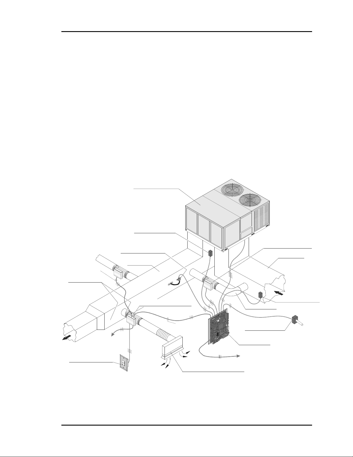
Typical HVAC Unit
(Packaged or Split System)
LOCAL COMM LOOP
ZONE CONTROLLER
Above Corridor
( Preferred Location )
Zone Sensor
(4-1/2' to 5'; Shoulder Height)
TWISTED PAIR
WITH SHIELD TO
LOCAL COMM LOOP
TWISTED PAIR WITH
SHIELD TO OTHER
ZONE CONTROLLERS
OR CV CONTROLLERS
Static Pressure Pickup
(2/3 Of The Way Down Main Duct)
Supply Duct
Supply Temp Sensor
(Ahead of Bypass Takeoff)
Zone Damper and Control
( Over Corridor for Easy Service )
LOCAL COMM LOOP
ZONE CONTROLLER
TWISTED PAIR
WITH SHIELD TO
Diffuser at Perimeter Wall
(Direct Airflow Inward Towards Center of Area)
Bypass Damper
( Locate Where Easily Accessible )
Duct to Return
(Preferred)
Outdoor Air Sensor
(Mount Away From Direct Sunlight))
Zone Manager
NETWORK COMM LOOP
WITH SHIE LD TO
NEXT ZONE MANAGER
TWISTED PAIR
Return Duct
Return Temp Sensor
(Avoid Mixed Air Area)
Figure 1-2: Typical HVAC Unit Installation
Design Guide 1-3
Page 8

Section 1 Auto-Zone Plus
Other new features provided with the Zone Manager controller include the ability to
control a modulating chilled water valve for cooling and/or a modulating hot water valve
or SCR electric heater for heating. This modulating cooling and/or heating requires the
addition of the OE352 2 Slot Expansion Base Board with an OE355 4 Analog Output
Board mounted on it. The base board/expansion board assembly connects to the Zone
Manager via a modular cable. The Zone Manager has the ability to control up to 2 stages
of cooling and 2 stages of heating. When more stages are required the same OE352 2
Slot Expansion Base Board can be populated with up to (2) OE357 4 Relay Output
Expansion Boards to provide up to 4 additional stages of heating and/or cooling.
This new version also has Optimal Start capabilities. A target zone can be selected as a
control point and the Zone Manager will start the system at the correct time to make sure
the zone setpoint temperature is reached according to the scheduled start time based on
the soak time that the user configures. The new Zone Manager can now also be
configured to allow control of your HVAC unit based on the heating or cooling Supply
Air Temperature.
The Auto-Zone Plus System Manager allows multiple Zone Managers to be programmed
and monitored from a central operator's panel. Single-zone constant volume rooftop
HVAC units can also be connected to the Auto-Zone Plus communication network,
allowing for both multizone and single-zone equipment to be controlled from the same
system.
Substantial savings can be realized using the Auto-Zone Plus system instead of having to
install multiple single zone Constant Volume rooftop units to accommodate multiple
zone requirements. The Auto-Zone Plus system is versatile and can be used with any
packaged roof top or indoor HVAC unit or any split system HVAC unit. It controls a
variety of terminal unit functions including pressure dependent or pressure independent
single duct terminals and series or parallel flow fan terminals.
The optional Prism color graphics software package is available to provide for on site or
remote monitoring via a personal computer.
1-4 Design Guide
Page 9
Auto-Zone Plus Section 1
Description of System Components
A typical Auto-Zone Plus system is comprised of the following basic components.
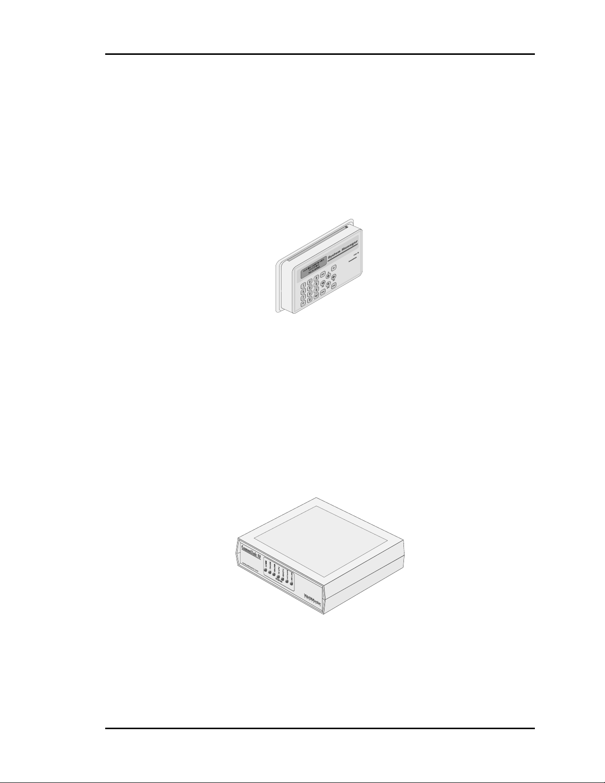
System Manager
The microprocessor based System Manager allows multiple Zone Managers and any
single-zone constant volume HVAC units to be programmed and monitored from a
central operator's panel. The System Manager is connected to the Auto-Zone Plus
communication network and can be wired to any local loop connection on the system.
The System Manager is mounted in an attractive, white plastic housing, suitable for wall
mounting. A four line by twenty character backlighted LCD display and membrane
keypad provide a user friendly interface. All system variables, setpoints, and values can
be viewed and modified from the System Manager. Menu driven programming makes the
Auto-Zone Plus easy to set up and operate without the need for specialized training.
CommLink IV
The OE361-12 CommLink IV Communications Interface allows computer access into the
Auto-Zone controls system and also provides communications across multiple local
communications loops on the control system.
The CommLink IV comes packaged in an attractive beige colored plastic enclosure. The
CommLink IV is powered by a small plug-in transformer that is included. Locally, an
optional on-site personal computer with Prism software installed may be connected to the
CommLink IV to provide direct access to system control parameters. A USB cable (6 ft.
long) is provided with the CommLink IV for connection to your computer.
Design Guide 1-5
Page 10
Section 1 Auto-Zone Plus
Remote telephone access to the control system can be obtained by purchasing the optional
OE419-06 Remote Link II modem. With the optional Remote Link II modem installed,
the control system can be accessed remotely by using another Remote Link II modem
(purchased separately) connected to a personal computer with Prism software installed at
the remote location. With the Remote Link installed at the job site, the CommLink IV can
be configured to call a pager or cell phone number if an alarm condition occurs.
An optional OE415-02 IP Module Kit is also available that provides an Ethernet
connection to the controls system from any computer connected to your building’s LAN.
It can also be configured to allow access to the control system from the Internet if your
Ethernet firewall is configured for this option.
Zone Manager
The Zone Manager is a microprocessor based controller which monitors up to sixteen
zones in the system. The zone manager controls the zoned HVAC unit to satisfy the
requirements of each individual zone while maintaining efficient operation and comfort.
The Zone Manager operates the fan, heating, cooling, duct static pressure, and
economizer functions. Each Zone Manager also features time scheduling, night set back,
trend logging of sensor values, and automatic changeover.
1-6 Design Guide
Page 11
Auto-Zone Plus Section 1
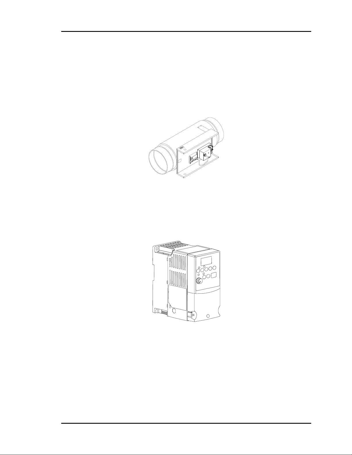
Bypass Damper or VFD Control
A Bypass damper or Variable Frequency Drive (VFD) is used to control the duct static
pressure. When using bypass damper control, the Zone Manager sends a signal to the
bypass damper actuator to maintain duct static pressure by opening and closing a damper
in order to bypass a portion of the discharge air stream back into the return air duct of the
HVAC unit in response to the duct static pressure.
When a VFD is used, the Zone Manager sends a 0–10 VDC signal to the VFD to
maintain duct static pressure by causing the VFD to change the Supply Fan motor speed
thereby increasing or decreasing the air flow in response to the duct static pressure.
Minimum airflow requirements of the heat exchanger must be considered when using a
VFD on units that have heating. See the design section of this manual for specific
recommendations and information.
Design Guide 1-7
Page 12

Section 1 Auto-Zone Plus
Zone Controller
The Zone Controller monitors space temperature and positions a damper to maintain
proper air flow to the assigned zone in order to achieve desired comfort and ventilation
levels.
If the current supply air temperature in the duct will benefit the local zone temperature
setpoint, the zone damper will modulate the air flow across the damper as needed to in
order to satisfy the setpoint temperature. If the supply air will not benefit the zone (such
as hot air in the duct when the space is calling for cooling), the controller will direct the
damper actuator to a minimum position and wait for a change in the supply air
temperature to occur that will help achieve the heating or cooling setpoint.
Constant Volume Controller
The Constant Volume (CV) Controller is a microprocessor based controller designed to
operate packaged roof top HVAC units. Up to thirteen stand alone CV controllers can be
connected to each Zone Manager's local communications loop to provide a fully
integrated multizone/single-zone control system. The CV controller operates the fan,
heating, cooling, and economizer functions. Each CV controller also features time
scheduling, night set back, trend logging of sensor values, and automatic changeover.
1-8 Design Guide
Page 13
Auto-Zone Plus Section 1
V
J
T
A
/
V
Y
V
A
V
A
T
A
T
V
A
V
A
T
A
T
V
A
V
A
T
A
T
V
A
V
A
T
A
T
V
V
T
V
A
/
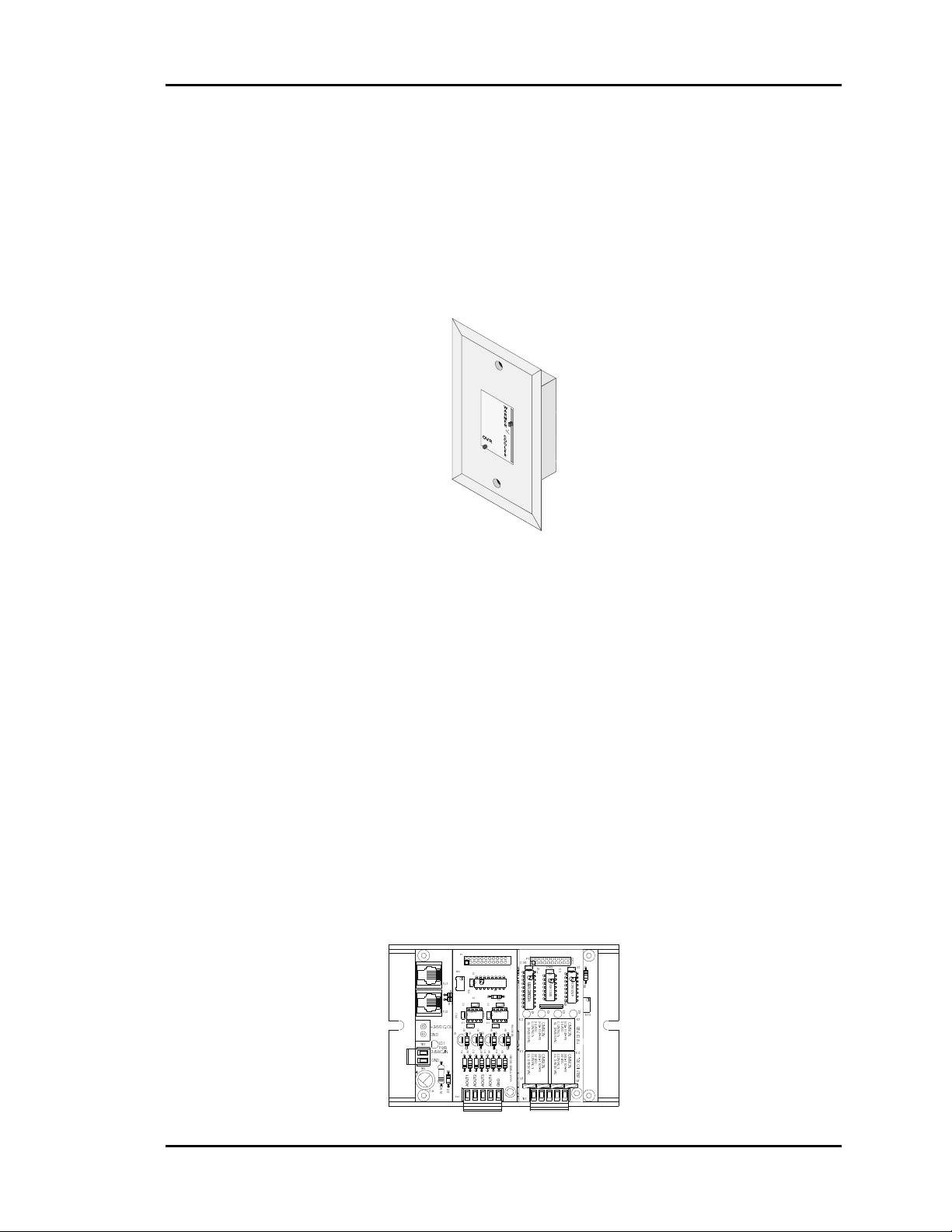
Zone Sensor
The patented zone sensor is of a flush, wall mounted design. A special plate on the face
of the sensor accurately senses space conditions. As a result of its unique design, the zone
sensor rejects the influence of internal wall temperature effects. The sensor comes in four
different configurations:
• Sensor only
• Sensor w/push-button override (Override time fixed at 2 hours)
• Sensor w/setpoint adjustment
• Sensor w/override & setpoint adjustment
Any combination of these sensor configurations can be used with the system.
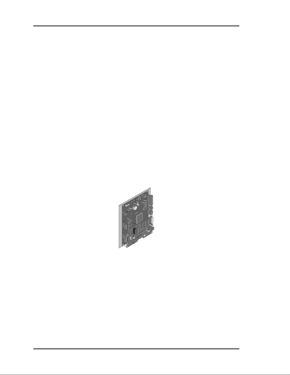
Expansion Boards
The Zone Manager is designed to utilize expansion boards to provide additional
versatility to the control system. The OE352 2 Slot Expansion Base Board connects to the
Zone Manager via a modular cable and with the OE355 4 Analog Output Expansion
Board mounted on it can provide for 2 additional analog outputs to control a modulating
hot water heating valve or SCR electric heater and/or modulating chilled water valve. The
OE357 4 Relay Output Board can also be mounted on the 2 Slot Expansion Base Board
and provides for up to 6 total stages of heating and/or cooling combined when two
OE357 Boards are used.
P1
P1
RV1
U1
PJ1
R9
CX1
R7
D2D1 R8
C1
R11
U2
PJ2
LM358
CX2
C3
+24VDC-OUT
R2
Q1
Q2R3Q4
GND
C1
LD1
TB1
R13
PWR
D1R6D2R7D4D3R8
24VAC-IN
GND
TB2
C6
Design Guide 1-9
CX3
7824CT
MC
AOUT1
AOUT2
R
D
1
3
4
TB1
VR2
VR3
U3
U1
CX3
C4
Q3
MC
AOUT3
CX1
R1
P82B715P
C2
LM358
R4
C2 C3
7805ACT
GND
AOUT4
P1
CX1
P1
U
L
R
R
R
N
3
2
1
2
8
0
3
K2
U
L
5
2
R5
5
0
YS101786
C
K1
R9
U
L
5
2
5
0
C
7812CT
1
4 AOUT MOD. I/O BD.
MC
R4
B1
L
HAANI
T
S
P
I
L
I
H
P
1
C
2
4
O
N
D
C
C
:
C4 C5
C
2
4
O
N
D
C
C
:
VR5
P2JP2
CX2
1
U
D
L
M
3
5
8
N
U2
G
O
5
M
L
-
1
R
1
O
4
N
P
-
P
S
G
O
5
M
L
-
R
1
1
O
4
N
P
-
P
S
7824CT
MC
3
X
C
U3
2
U
P
C
7
R4R
R
4
F
5
6
H
8
C
5
7
CX2
0
4
R10
4
P
N
1
N
R
R1
4
3
K
K2K
K
R12
2
K3
G
C
2
O
U
S
4
L
O
5
L
M
L
O
N
-
5
D
1
R
0
C
1
O
9
2
4
S
C
5
7
N
P
M
1
0
-
1
:
P
0
0
S
O
1
1
C
S
D
7
Y
U
8
L
0
G
C
K4
2
O
U
R
4
L
5
O
M
L
.
I
N
5
-
D
R
1
D
O
C
1
O
B
2
4
C
5
N
P
O
0
-
I
:
P
S
Y
C
L
R
4
7824CT
MC
4
R6
Page 14

Section 1 Auto-Zone Plus
Design Considerations
Consider the following items when designing an Auto-Zone Plus system.
Zone Diversity
An Auto-Zone Plus system is designed to improve tenant comfort by dynamically rebalancing the air distribution when used with a typical constant volume rooftop
heating/cooling unit. If zones with extremely different load conditions are serviced by a
single rooftop unit, the result will be poor control and excessive wear due to cycling of
the equipment.
It is especially important to avoid mixing interior zones (which require cooling all year)
with exterior zones (which may require constant heat during winter months). If you must
mix zones under these conditions, consider using either VAV boxes with heat or separate
baseboard heat on exterior zones. Auto-Zone Plus systems offer a variety of methods to
control additional zone heat to help you avoid problems.
Group similar loads on an individual unit and use more than one zoned unit if required.
Any special loads can be handled by using separate constant volume units.
The Auto-Zone Plus system offers the designer considerable flexibility by allowing both
multiple-zoned units and single-zone units to be connected within a single simple system.
Cooling - Partial Load Conditions
The engineer must be aware of several potential problems when applying an Auto-Zone
Plus system during cold weather operation.
Low Ambient Temperature Lockout
During very cold weather it is common for mechanical systems to have “low temp
lockouts” which protect equipment from damage if operated under these conditions.
Auto-Zone Plus also provides user programmed lockouts for protection purposes,
although mechanical safeties should always be used as the final stage of protection.
If the rooftop unit services interior zones with thermal loads which require cooling when
outside temperatures are below the safe operating limits for your equipment, you should
seriously consider installing an economizer on your rooftop unit. The Auto-Zone Plus
control system is designed to take advantage of an economizer if it is installed. The use of
an economizer will save money on utilities and provide comfort under conditions when it
is not possible to operate the mechanical cooling system.
1-10 Design Guide
Page 15

Auto-Zone Plus Section 1
Low Supply Air Temperatures
Under lightly loaded conditions much of the supply air may be bypassed back into the
return air side of the system. This bypassing will result in the lowering of the supply air
temperature, which may result in the supply air temperature reaching the low temp safety
limit. If the supply air low temp safety limit is exceeded, the control system will “cut-off”
the mechanical cooling to protect it from damage. Excessive cycling of the mechanical
system will result if this condition persists. Comfort may also suffer if the system cannot
run long enough to satisfy cooling demands.
A number of things can be done to reduce this problem. Some of these things depend
upon the type of installation.
• Avoid oversizing the unit. Do your load calculations carefully. Since Auto-Zone Plus
directs the heating or cooling to the zones which require it, you may find that you can
use a smaller unit in many cases. Oversizing is the number one cause of excessive low
supply air temperature cycling.
• Increase your cooling minimum airflow or damper position settings to allow more air
during cooling operation. Be careful to avoid settings which are so high you cause
over cooling of the spaces. Find a compromise position.
• Bypass the air into the plenum instead of into the return air intake. Be careful if you
use this method since you may get “dumping” of cold air from your return air grilles.
This method works best with plenum returns, do not use this method with ducted
returns unless you have carefully considered the consequences.
• Increase your static pressure setpoint to help reduce the amount of air being bypassed.
Be aware of increased noise levels and the cost of operation if you use excessive static
pressures. This will not work if you are using pressure independent zone controllers,
since they will maintain a constant flow of air to the zones regardless of duct static
pressure. This technique will likely cause over cooling of the spaces due to increased
airflows at minimum positions.
Design Guide 1-11
Page 16

Section 1 Auto-Zone Plus
Warning: If the fan system has the capability of producing static pressures which
could damage ductwork you must provide a manual reset, high
pressure limit switch to cut-off the fan system in the event of high
duct static. Do not use your Auto-Zone Plus system as
a safety device!
• Use an Economizer. Although this is not a cure-all, it greatly improves operation
during cool weather when cooling loads are minimal. Using an Economizer also
improves ventilation and lowers operating costs.
1-12 Design Guide
Page 17

Auto-Zone Plus Section 1
Heating - Partial Load Conditions
Heating difficulties are less common than cooling difficulties. They are similar in nature,
however, and the cures are generally the same.
• Increase the Heating minimum setpoints on as many zones as possible.
• Increase the static pressure setting as high as is practical. Increasing static pressure
does not help if you are using pressure independent operation.
• Bypass to plenum instead of the return air intake if acceptable.
• Do not oversize your equipment.
• Use auxiliary heat in either your VAV boxes or baseboard.
Caution: When using a VFD for duct static pressure control, the VFD control
must have its minimum speed setting configured to meet the minimum
airflow requirements of the installed heating equipment. This is
especially critical when using indirect fired gas heating since the heat
exchanger could be damaged if the heating airflow falls below the
minimum airflow recommended for the heat exchanger. If the unit is
equipped with electric heat, failure to meet minimum airflow
requirements of the electric heater could cause nuisance tripping of the
electric heaters safety devices. The minimum heating airflow required
for your HVAC unit should be available from your HVAC unit
manufacturer. See your VFD installation manual for information on
setting the minimum airflow.
Auto-Zone Plus has a number of auxiliary heat control options which provide solutions to
most problems. Refer to the Auxiliary Heat Control Options topic near the end of this
section.
Override Conditions
After-hours overrides can produce aggravated partial load conditions in both the heating
and cooling modes. The problem is most commonly caused by a single zone being
overridden for after-hours use. This causes the rooftop equipment to operate for only one
zone. The Auto-Zone Plus system offers an improved solution to this common problem
by allowing a single override to trigger a group of zones via a “global” override. This
allows the system to operate with sufficient load to reduce cycling caused by light load
conditions.
Design Guide 1-13
Page 18

Section 1 Auto-Zone Plus
Building Pressurization
If you are using an economizer, building pressurization must be addressed. Failure to
properly handle building pressurization may result in doors remaining open when the
economizer is operating. Pressurization problems can render economizer operation
useless. The following suggestions will help to avoid potential problems.
• Use powered exhaust when the system uses ducted returns. The return duct pressure
drop will cause most barometric relief dampers to function poorly or not at all. AutoZone Plus has the ability to control a powered exhaust whenever the economizer is
operating.
• Use a separate building pressure control which operates a relief fan or dampers.
1-14 Design Guide
Page 19

Auto-Zone Plus Section 1
Design Guide
There are seven basic steps to designing an Auto-Zone Plus system:
1. Zoning
2. Sizing the Central Unit
3. Duct Design Considerations
4. Room Air Motion / Diffuser Selection
5. Bypass Damper Sizing
6. VFD Considerations
7. Sizing Zone Dampers
Step #1 - Zoning
Determine the number of zones. A single air handler unit can have no more than sixteen
zones. If the number of zones exceeds sixteen then more than one Zone Manager will be
required.
The primary precaution to be taken in applying the Auto-Zone Plus System is to select the
zoning so that no zone will be at maximum (design) heating (or cooling) load when any
other zone requires the opposite temperature air to satisfy its load. For example,
depending on the wall, ceiling and floor material and location within the building (e.g.
top or middle floor), a typical floor of a building usually has a minimum of nine distinct
temperature or control zones that are affected uniquely by the outdoor load. These zones
are depicted in Figure 1-3 & Figure 1-4.
Depending on the size of the building and partition layout, some of these zones may
overlap or be insignificant from a zoning standpoint. For example, Zone 9 could be
multiple conference or computer rooms where additional zoning would be required, or it
could be as small as a corridor where no zoning is required. Similarly, zones 7 and 8
could have no external windows and no partitions between them and could be considered
a single zone. Zone 6 could be divided into multiple offices with full partitions between
them, thus requiring separate Zone Controllers because of different internal loads, but the
same external load.
Generally speaking, the greater the number of individual Zone Controllers, the greater the
comfort. The designer will have to look at the specific building, balancing the costs of
multiple zones with the added comfort and energy savings possible with multiple zones,
to match the building owner's requirements.
Design Guide 1-15
Page 20
Section 1 Auto-Zone Plus
It is important to recognize that all buildings have some purely internal zones, such as
Zone 10, which may contain separate offices/conference/computer rooms. These internal
zones will normally have high cooling requirements year around while external zones
(1,2,3, etc.) could be at or near design heating load requirements during the winter
months. This diversity can be used (if properly zoned with multiple HVAC units serving
similar loads and zones) to save energy. However, a single HVAC unit is used to serve
zones with opposed cooling and heating demands as shown in Figure 1-3 the resulting
system will be very energy inefficient and comfort levels in the building will not be
satisfactory.
9
8
7
1
10
6
2
3
5
4
Figure 1-3: Incorrect Zoning of Typical Building
As previously mentioned, Figure 1-3 shows a misapplication of an Auto-Zone Plus (or
any heating/cooling changeover) system. Supplemental heat could be added to the
perimeter zones and controlled with the auxiliary heat control board from the Zone
Controller which would improve the performance of the system but still would not be
ideal. System performance would still generally be compromised and frequent
changeover from the heating to the cooling mode will occur during the heating season if
purely internal zones are combined on the same air-conditioning unit serving perimeter
zones.
1-16 Design Guide
Page 21
Auto-Zone Plus Section 1
The best approach would be to serve the interior zones with cooling only loads with a
separate constant volume HVAC unit (that could be zoned if desired between multiple
rooms with a similar load profile) instead of zoned with perimeter zones. Also perimeter
zones with South and West exposures typically have a higher cooling load than North and
East exposures. It is best to group the South and West perimeter zones together on the
same HVAC unit and the North and East perimeter zone together on another HVAC unit.
This will provide the best energy savings, prevent the HVAC units from changing over
from heating to cooling frequently and provide the best comfort for the occupants. This
recommended ideal system is depicted in Figure 1-4. If you use this approach you will
have the best flexibility and energy saving system design that is
possible.
9
8
7
10
6
5
4
Figure 1-4: Correct Zoning of Typical Building
1
2
3
Design Guide 1-17
Page 22

Section 1 Auto-Zone Plus
Step #2 - Sizing the Central Unit
Because the zones are controlled with variable air volume, it is unlikely that all zones will
be at design load at the same time. The zoning allows for the diversity of loads to be
taken into account and will often provide better comfort with a smaller HVAC unit.
In sizing the system, the individual zone loads should be calculated using any dependable
load estimating program. Because of diversity, the central unit should be selected for the
instantaneous peak load, not the sum of the peak loads, as would be done with a constant
volume single zone system. Consider the following when sizing the central unit.
• Size the peak cooling load based on the month and hour of the greatest total
building/system load.
• Heating should be sized for the lowest design temperature with an additional margin
for morning "pickup". This margin is generally recommended to be 20 to 25 percent
of base design.
Step #3 - Duct Design Considerations
The AZ Plus system uses a typical low pressure duct design. To reduce noise problems
duct pressures should not exceed 1 inch W.C.
Primary trunk ducts should not be "undersized." This is especially true for "pressure
dependent" systems. Pressure dependent refers to the typical Auto-Zone, Zone Controller
without the air flow sensor. With larger trunk ducts, it is easier to assure relatively
constant pressure to each zone. Runs should be as short as possible, and the trunk duct
system kept as symmetrical as possible to facilitate system balancing. Wherever possible,
run the trunk ducts above corridors and locate the zone dampers above corridors to reduce
the noise in the space and facilitate service of the units. Trunk ducts should be sized for no
more than 0.1 inch W.C. drop per 100 feet., and a maximum duct velocity of 2000 FPM.
Note: For pressure independent terminal units with velocity sensors and
conventional "VAV" boxes properly selected for "quiet" operation, this 2000
FPM rule can be exceeded by up to 50 percent. The designer, however, should
be very experienced in VAV system design before considering modification of
this general rule
Typical VAV systems with pressure independent terminals use the static regain method
for sizing ducts. The typical Auto-Zone Plus system is a low-pressure, pressure
dependent system that utilizes conventional unitary air-conditioning units. These systems
should use the equal-friction method of sizing the ducts, and use the maximum loss of 0.1
inch per 100 feet as described above.
.
1-18 Design Guide
Page 23

Auto-Zone Plus Section 1
Step #4 - Room Air Motion/Diffuser
Selection
Air motion is a consideration for occupant comfort. The selection of diffusers for an
Auto-Zone Plus system requires more care than a constant volume system due to varying
flow of air into the zones. Slot diffusers are recommended due to their superior
performance at low air flows. Because the zone air flow is variable volume, lower cost
round or rectangular diffusers that were satisfactory for constant volume may prove
unsatisfactory with an Auto-Zone Plus system. These diffusers may result in "dumping"
of the cold air at low flows in the cooling mode, and insufficient room air motion at low
air flows in the heating mode. Although high air motion in the heating mode can be
undesirable, a slot diffuser with a high induction ratio generally helps to reduce room air
"stratification" when the heating comes from a ceiling diffuser. Linear slot diffusers
should be properly selected for the air flow and "throw" suited to the specific installation
or zone.
Additional factors to consider in diffuser selection are sound level and throw at design
flow. Generally, multiple diffusers will result in lower sound levels in the space, but this
must be balanced with the additional hardware and installation costs. It is commonly
recommended that slot diffusers be located near the perimeter or outside wall with the
airflow directed into the room. Consult your diffuser supplier or catalog for proper
diffuser sizing and location.
Series fan boxes may be used instead of zone dampers where higher induction rates are
desirable. If the heat loss on perimeter walls is high, such as large areas of glass, the use
of Series Fan Boxes may be indicated to maintain higher induction rates to offset
“downdrafts.” If the heat loss is greater than 275 BTUH/LINEAR FOOT, you should use
high quality slot diffusers next to the outer wall with the airflow directed inward to
counteract downdrafts during heating. Serious downdraft problems occur when heat
losses exceed 400 BTUH/LINEAR FOOT and both high induction diffusers and series
fan boxes are recommended.
Step #5 - Bypass Damper Sizing
Using a load calculation program, the bypass damper should be sized to give you the
maximum CFM of air to be bypassed, typically 60 to 70 percent of the HVAC units rated
capacity.
To size the damper, select a damper from the table based on calculated bypass CFM and a
maximum velocity between 1750-2250 FPM. When determining the bypass duct size, be
sure to take into account any transition fittings and associated pressure drops. (See Table
1-1: Damper Sizing Chart)
Design Guide 1-19
Page 24

Section 1 Auto-Zone Plus
Whenever possible, use a single bypass damper and round duct for the bypass. If space
limitations or total airflow requires it, multiple bypass dampers can be controlled in
parallel.
For proper control of the Bypass Damper the static pressure sensor location is very
important. See Figure 1-5: Locating the Static Pressure Sensor for proper mounting
locations.
Step #6 - VFD Considerations
When using a VFD instead of a bypass damper for static pressure control, it is important
to consider the minimum fan speed that will still allow for proper airflow across the
electric heating element or gas fired heat exchanger. You should consult the HVAC unit’s
selection and design information regarding the minimum airflow that is allowed to
prevent damage to the heat exchanger in the case of gas fired equipment and prevent
nuisance tripping of the thermal safety devices when you are using an electric heater.
The VFD Controller on your HVAC unit must be configured so that the airflow never
falls below the minimum required by the heat exchanger. The WattMaster controller will
only modulate the VFD to control the fan speed in response to the static pressure setpoint
that you have set.
Also the wiring supplying the 0-10 VDC signal between the Zone Manager and the VFD
should be 18 gauge minimum 2 conductor twisted pair with shield to help prevent signal
feedback to the Zone Manager. This wire is available from WattMaster as part number
WR-LL-WG-18 or you can use Belden #82760 or equivalent wire.
For proper control of the VFD, the Static Pressure Sensor location is very important. See
Figure 1-5: Locating the Static Pressure Sensor for proper mounting locations.
1-20 Design Guide
Page 25

Auto-Zone Plus Section 1
p
Preferred Location
If the trunk ducts are properly sized for
minimum pressure drop, the location of
the static pickup probe is not particularly
critical. It should ideally be located at
right angles to the airflow in a straight
section of the supply duct approximately
2/3 the distance of the total length of the
supply duct. Also the probe should be
located not less than 3 duct diameters
downstream and 2 duct diameters
upstream of any elbow or takeoff.
Less Than Ideal, But
Acceptable
Since the "ideal" location is often
difficult to find in an installation, a
location in the main trunk where the
tip is not in a "negative pressure area"
(e.g. just downstream of the inside
curve of an elbow) or an area where
the tube opening is directly impacted
by the velocity of the supply air.
Another option is to use (2) Static
Pressure Probes and tie them together
with a tee. Use equal lengths of tubing
for each sensor and run the third leg of
the tee back to the Static Pressure
Sensor. This will average the pressure
readings of the two duct runs.
Least Desirable, But Acceptable
If the supply duct comes directly from
the unit and immediately splits in
opposite directions without a curved
duct split, the pressure pickup should be
located ahead of the split, or as close to
it as possible to it, even if the bypass
damper(s) are located downstream of the
split.
Supply Air
Temp. Sensor
Supply Air
Duct
Supply Air
Supply Air
Duct
Supply Air
Temp. Sensor
Static Pressure
Sensor
Supply
Duct
Tee
Tubing To Be Equal
Length And Size
Fan
Bypass
Damper
Supply
Fan
Static Pressure
Probes
Picku
Supply
Fan
Static Pressure
Pickup Probe
Static Pressure
Pickup Probe
Bypass
Damper
Supply Air
Temp. Sensor
Static Pressure
Sensor
Bypass
Damper
Return Air Duc t
3D
Min.2DMin.
Return Air Duct
Static Pressure
Return Air Duct
Return Air
Tem p. Se ns or
Sensor
Return Air
Tem p. S en sor
Return Air
Temp. Sensor
Figure 1-5: Locating the Static Pressure Sensor
Design Guide 1-21
Page 26
Section 1 Auto-Zone Plus
Step #7 - Sizing Zone Dampers
Use a load program to determine the peak load for each zone. These calculations will be
used in selecting the appropriate zone damper sizes. WattMaster can provide either round
zone dampers or rectangular zone dampers for your zones
Using the maximum acceptable velocity for a branch duct (typically 1000-1500 FPM for
minimal noise), find the smallest damper that will deliver the required CFM as
determined by the load program.
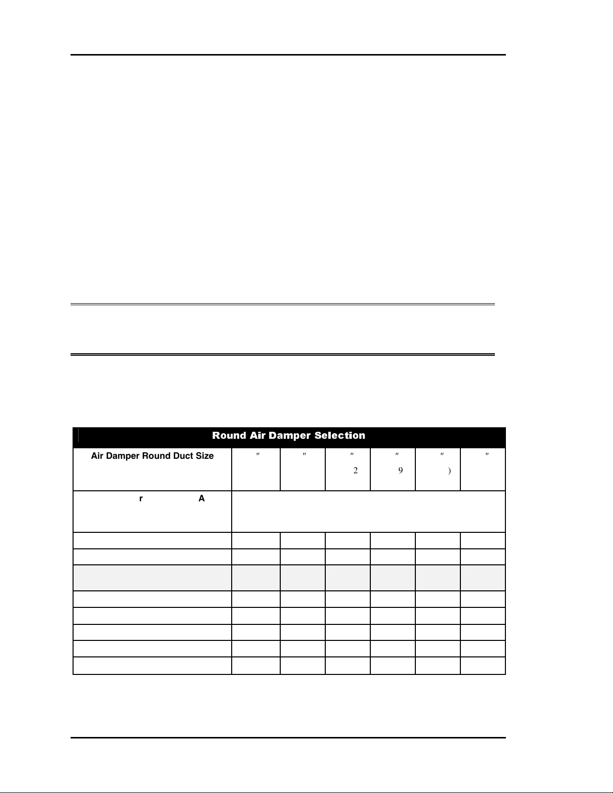
Round Zone Damper Selection
Locate the branch velocity used in the duct design program on the left hand column of the
damper sizing chart (Table 1-1). Move across the chart and find the damper which will
provide the acceptable CFM to meet zone requirements.
Note: Compare the damper size selected against the duct size to determine if the
next size up or down will provide acceptable performance without requiring a
transition fitting.
One additional damper may be slaved together for large zones. See zone wiring diagram
for details. This should be reserved for situations when it is not practical to use a single
large damper.
Air Damper Round Duct Size
Velocity through Round Air
( Area Ft
Damper
750 - P.I. or P.D. Zone
1000 - P.I. or P.D. Zone
Maximum CFM For P.I. Zone
1250 – P.D. Zone Only
1500 – P.D. Zone Only
1750 - Bypass Only
2000 - Bypass Only
2250 - Bypass Only
2
(FPM)
Damper
)
Round Air Damper Selection
6″
(0.188)
141 254 399 577 788 1031
188 338 532 769 1050 1375
206 413 634 921 1264 1608
235 423 665 961 1313 1718
282 507 798 1154 1575 2062
329 592 931 1346 1838 2405
376 676 1064 1538 2100 2749
423 761 1197 1730 2363 3094
8″
(0.338)
Volume through Round Air Damper
10″
(0.532)
(CFM)
12″
(0.769)
14″
(1.050)
16″
(1.375)
Table 1-1: Round Damper Sizing Chart
1-22 Design Guide
Page 27
Auto-Zone Plus Section 1
Round Damper
Blade Assembly
Zone Controller
1/2" Foil Faced
Insulation
W
A
O
I
R
L
F
F
L
R
I
O
A
W
Actuator
Control Enclosure
(Cover Removed)
VAV/Zone Round Damper Dimensional
Data
Duct Diameter A B C
6″
8″
10″
12″
14″
16″
19.00 5.88 9.38
19.00 7.88 11.38
19.00 9.88 13.38
22.00 11.88 15.38
22.00 13.88 17.38
22.00 15.88 19.38
Table 1-2: Round Damper Dimensional Data
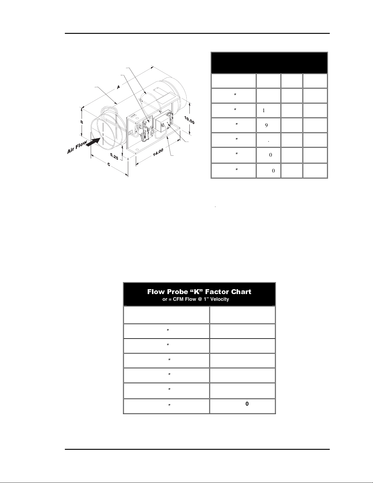
Pressure Independent Round Damper “K” Factor
Pressure Independent Round Air Dampers utilize “K” factors to correctly measure and
read CFM values. These “K” factors represent the airflow that will pass through a given
size damper at 1” of velocity pressure. These “K” factors must be programmed into the
control system for all pressure independent dampers. See Table 1-3 for a list of “K”
factors by round damper diameter used.
Flow Probe “K” Factor Chart
K Factor = CFM Flow @ 1” Velocity Pressure
Damper Diameter Flow Probe “K” Factor
6″
8″
10″
12″
14″
16″
474
950
1417
2120
2908
3700
Table 1-3: Pressure Independent “K” Factors
Design Guide 1-23
Page 28
Section 1 Auto-Zone Plus
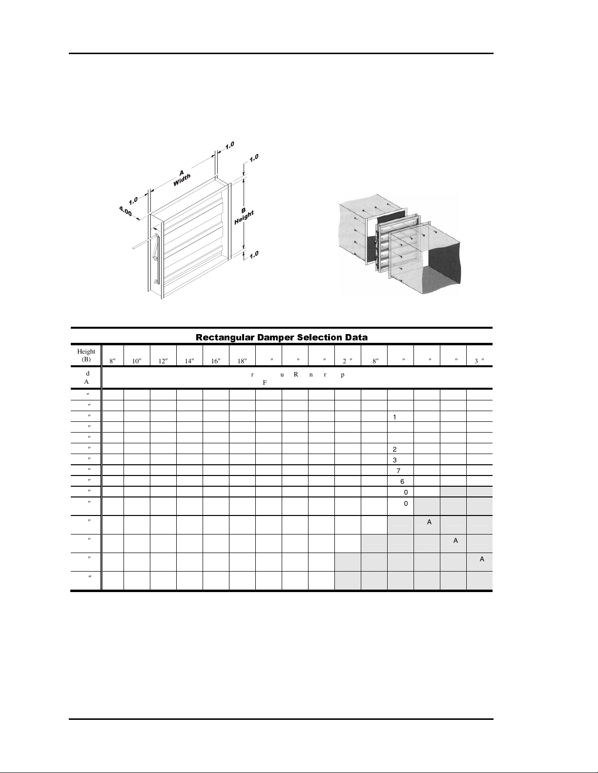
Rectangular Zone Dampers
The Rectangular Damper is used in applications where rectangular ducts are specified or
required because of space limitations or job requirements. The Rectangular Damper
utilizes opposed blades for improved air flow control. See Table 1-4 for sizing info.
Dimensional Data Typical Installation
Height
(B)
Width
(A)
10″ 510 590 690 800 910 1030 1150 1260 1380 1500 1610 1730 1840 2000 2080
12″ 560 650 730 850 970 1090 1210 1330 1460 1580 1700 1820 1940 2060 2190
14″ 660 770 880 1030 1180 1330 1480 1630 1760 1910 2060 2210 2360 2510 2640
16″ 750 890 1030 1200 1370 1540 1710 1880 2060 2230 2400 2570 2740 2910 3090
18″ 770 980 1180 1380 1580 1780 1980 2180 2350 2550 2750 2950 3150 3350 3540
20″ 850 1090 1330 1550 1770 1990 2210 2430 2650 2870 3090 3310 3530 3750 3990
22″ 930 1210 1480 1730 1980 2230 2480 2730 2950 3200 3450 3700 3950 4200 4440
24″ 950 1290 1630 1900 2170 2440 2710 2980 3250 3520 3790 4060 4330 4600 4880
26″ 990 1390 1780 2080 2380 2680 2980 3280 3550 3850 4150 4450 4750 NA NA
28″ 1070 1500 1930 2250 2570 2890 3210 3530 3850 4170 4500 4820 NA NA NA
30″ 1020 1550 2080 2430 2780 3130 3480 3830 4150 4500 4850 NA NA NA NA
32″ 1090 1660 2230 2600 2970 3340 3710 4080 4450 4820 NA NA NA NA NA
34″ 1150 1770 2380 2780 3180 3580 3980 4370 4750 NA NA NA NA NA NA
36″
″
10″ 12″ 14″ 16″ 18″ 20″ 22″ 24″ 26″ 28″ 30″ 32″ 34″ 36″
8
8″ 410 530 640 740 850 970 1080 1190 1300 1410 1520 1630 1740 1850 1970
1060 1790 2520 2670 3090 3510 3930 4350 5040 NA NA NA NA NA NA
Rectangular Damper Selection Data
Airflow Through Rectangular Damper
CFM @ 1000 FPM Velocity
Notes:
1.) Zone Dampers should be sized based on the required zone CFM. The table above is calculated based on 1000 FPM velocity through
the Rectangular Damper. Zone Damper recommended velocity is 1000 - 1500 FPM. Select 1000 FPM or less for quiet operation. For
other velocities, use the following multipliers to obtain the correct CFM: 500 FPM = 0.5, 750 FPM = 0.75, 1250 FPM = 1.25, 1500 FPM =
1.5, 2000 FPM = 2.0, 2250 FPM = 2.25.
2.) Bypass Dampers should be selected for 60% to 70% of the HVAC units rated CFM capacity. Recommended Bypass Damper velocity
-
Table 1-4: Rectangular Damper Sizing Information
1-24 Design Guide
Page 29

Auto-Zone Plus Section 1
Auxiliary Heat Control
Options
The Auto-Zone Plus system offers the user a variety of methods to deal with zone heating
requirements. When deciding how to handle zone heating requirements the user should
consider the following:
• Does the rooftop unit have heat?
• Are you using fan powered boxes?
• Is auxiliary heat used such as baseboard or radiant ceiling panels?
If the zone has some type of heat, the user must consider how the heat is to be used.
Typical questions that should be asked:
Q: Should the zone heat be used as a first stage where it will become active before a
heating demand is created at the rooftop unit?
A: This mode is useful if you expect to have both heating and cooling demands at the
same time. The zone will use it’s own heat and allow the rooftop unit to continue to
provide cooling for other zones. This mode is also useful if the rooftop unit does not
have any heating capabilities.
Q: Is the zone heat only to be used as a second stage, where it will be activated only if
the rooftop unit cannot maintain the space temperature, such as during very cold
weather?
A: In this mode of operation the rooftop will examine the heating and cooling demands
and try to satisfy all of the zones by switching between heating and cooling as
required. The zone heat will only be activated if the zone temperature falls below a
selected limit.
Q: Should the zone heat be locked out if the rooftop unit is supplying warm air?
A: In many instances it is desirable to use the rooftop heating whenever possible and
only use zone heat when the rooftop unit is in cooling or vent mode. This often
provides the most cost effective operation since zone heat is typically electric. This
mode of operation will lockout zone heat if the rooftop is delivering heated air.
Design Guide 1-25
Page 30

Section 1 Auto-Zone Plus
The following paragraphs describe the operation of each of the relays on the optional
relay expansion board. The user can choose the appropriate relays for any given
application.
Relay #1 - Parallel Fan
If the Zone is in cooling mode or vent mode, the parallel fan can activate anytime the
zone temperature drops 0.5°F below the heating setpoint. It de-activates when the
temperature rises above the heating setpoint. The space temperature must be below the
Aux Heat Setpoint in the occupied mode, before the Parallel Fan relay can be energized.
Relay #2 - Box Heat
If the Zone Manager is in cooling mode or vent mode then the box heat can activate
anytime the zone temperature drops 1.5°F below the heating setpoint. It de-activates when
the temperature rises to within 1.0°F of the heating setpoint. Box Heat is not allowed to
activate in the heating mode when there is hot air being supplied by the air handling unit.
This output was intended to allow zone re-heat while the Zone Manager is satisfying
cooling demands in other zones. The space temperature must be below the Aux Heat
Setpoint in the occupied mode, before the Box Heat relay can be energized.
Relay #3 - Aux Heat
In the occupied mode, the Aux Heat can activate anytime the zone temperature is 0.5°F
below the Aux Heat Setpoint. It de-activates when the temperature rises 0.5°F above the
Aux Heat Setpoint. In the Unoccupied Mode, the Aux Heat uses the Unoccupied Heating
Setpoint with the same deadband values mentioned above. This prevents the zone from
maintaining the same Aux Heat Setpoint at night that it does during the daytime.
This output was intended to allow zone heating to augment the normal Heating Mode and
also to allow a zone an attempt to satisfy its own heating needs before creating a Heating
Demand at the Zone Manager.
Relay #4 - Series Fan
The series fan runs anytime the main fan is running. This includes Occupied and
Unoccupied Modes. The fan can only start running when the Zone Damper is closed, so it
determines that the damper is closed before starting the fan.
Modulating Box Heat Available
Modulating Heat is available by using the OE322 Expansion Board but requires special
consideration. The OE322 board can provide a 0-10 VDC modulating signal for a
Modulating Hot Water Valve or an SCR Electric Heating Coil Controller. Please contact
WattMaster for more information.
1-26 Design Guide
Page 31

Auto-Zone Plus Section 1
Index:
“K” Factor........................................... 23
1000-1500 FPM .................................. 22
1750-2250 FPM .................................. 19
2000 FPM rule .................................... 18
275 BTUH/LINEAR FOOT................ 19
4 Relay Output Expansion Board.......... 4
400 BTUH/LINEAR FOOT................ 19
Air Motion .......................................... 19
Analog Output Board............................ 4
Auto-Zone Plus System
Diagram............................................. 2
Aux Heat ............................................. 26
AUX HEAT setpoint........................... 26
Auxiliary Heat..................................... 13
Auxiliary Heat Control Options.......... 25
Baseboard Heat ................................... 25
Box Heat ............................................. 26
Building Pressurization....................... 14
Bypass CFM........................................ 19
Bypass Damper
Defined.............................................. 7
Bypass Damper Sizing........................ 19
Ceiling Diffuser .................................. 19
Central Unit
Sizing ........................................ 17, 18
CommLink IV
Described .......................................... 5
Constant Volume Controller
Defined.............................................. 8
Constant Volume Rooftop Units........... 4
Conventions .......................................... 1
Cooling
Partial Load Conditions .................. 10
Damper
Sizing .............................................. 19
Design Considerations ........................ 10
Design Guide ...................................... 15
Diffuser ............................................... 19
Downdrafts.......................................... 19
Duct Design ........................................ 18
Duct Static Pressure .............................. 7
Ducted Returns.................................... 11
East Exposures .................................... 17
Economizer ............................. 10, 12, 14
Ethernet Connection.............................. 6
Expansion Boards
Defined.............................................. 9
Exposures
East.................................................. 17
North ............................................... 17
South ............................................... 17
West ................................................ 17
Fan Powered Boxes............................. 25
First Stage Heat................................... 25
Heating
Sizing .............................................. 18
Heating - Partial Load Conditions ...... 13
Heating Difficulties............................. 13
Heating Requirements......................... 25
High Duct Static.................................. 12
HVAC Unit Installation
Diagram............................................. 3
Incorrect Zoning
Diagram........................................... 16
Installation
HVAC Unit ....................................... 3
Internet .................................................. 6
IP Module Kit
Defined.............................................. 6
Linear Slot Diffusers........................... 19
Load Program...................................... 22
Low Ambient Temperature Lockout... 10
Low Supply Air Temperatures............ 11
Low Temp Lockouts ........................... 10
Modulating Box Heat.......................... 26
Modulating Chilled Water Valve.......... 4
Modulating Hot Water Valve................ 4
Noise Levels........................................ 11
Noise Problems ................................... 18
North Exposures.................................. 17
Optimal Start......................................... 4
Override Conditions............................ 13
Design Guide 1-27
Page 32

Section 1 Auto-Zone Plus
Oversizing
Unit ................................................. 11
Parallel Fan ......................................... 26
Partial Load Conditions
Cooling............................................ 10
Heating............................................ 13
Peak Cooling Load
Sizing .............................................. 18
Peak Load
Determining .................................... 22
Plenum Returns................................... 11
Powered Exhaust................................. 14
Pressure Eependent ............................. 18
Pressure Independent Round Damper
“K” Factor....................................... 23
Pressure Independent Zone
Controllers....................................... 11
Prism ................................................. 4, 5
Radiant Ceiling Panels........................ 25
Rectangular Damper Sizing ................ 24
Rectangular Zone Dampers................. 24
Relay #1 - Parallel Fan........................ 26
Relay #2 - Box Heat............................ 26
Relay #3 - Aux Heat............................ 26
Relay #4 - Series Fan .......................... 26
Remote Link II
Described .......................................... 6
Requirements
for Heating ...................................... 25
Rooftop HVAC Units ........................... 4
Rooftop Unit ....................................... 25
Room Air Motion................................ 19
Round Damper Sizing Chart............... 22
Round Zone Damper Selection........... 22
SCR Electric Heater.............................. 4
SCR Electric Heating Coil.................. 26
Second Stage Heat .............................. 25
Selection
Round Zone Damper....................... 22
Sensors
Described .......................................... 9
Series Fan............................................ 26
Series Fan Boxes................................. 19
Sizing
Central Unit..................................... 17
Rectangular Dampers...................... 24
Zone Dampers................................. 22
Slaved Dampers .................................. 22
Slot Diffusers ...................................... 19
Slot Expansion Base Board................... 4
South Exposures ................................. 17
Static Pressure Sensor
Locations......................................... 21
Static Pressure Sensor Location.......... 20
Static Pressure Setpoint....................... 11
Stratification........................................ 19
System Components.............................. 5
System Manager.................................... 4
Defined.............................................. 5
Temperatures
Low Supply Air............................... 11
Variable Frequency Drive (VFD) ......... 7
VFD................................................. 7, 13
VFD Control
Defined.............................................. 7
West Exposures................................... 17
Zone Controller
Defined.............................................. 8
Zone Controllers
Pressure Independent ...................... 11
Zone Dampers
Rectangular ..................................... 24
Sizing .............................................. 22
Zone Diversity..................................... 10
Zone Manager
Defined.............................................. 6
Requirements for............................. 15
Zone Sensor
Defined.............................................. 9
Zoning................................................. 15
Incorrectly ....................................... 16
1-28 Design Guide
Page 33

Auto-Zone Plus Section 2
Table of Contents
Installation Tips............................................................... 5
Zone Manager ..................................................................8
General.............................................................................................................................8
Zone Manager Components.............................................................................................9
Zone Manager Wiring....................................................................................................10
Zone Manager Addressing.............................................................................................11
Expansion Board Wiring................................................................................................12
Communications Loops .................................................14
Bypass Dampers ............................................................16
Bypass Damper Wiring..................................................................................................18
Zone Dampers................................................................ 19
Zone Controllers ............................................................20
Zone Controller Components.........................................................................................21
Zone Controller Wiring & Addressing ..........................................................................23
Slaved Zone Controller Wiring......................................................................................24
Auxiliary Relay Board for Zone Controllers .................. 25
General...........................................................................................................................25
Auxiliary Relay Board Wiring .......................................................................................26
Auxiliary Relay Sequence of Operation.........................................................................27
Relay #1 - Parallel Fan...............................................................................................27
Relay #2 - Box Heat...................................................................................................27
Relay #3 - Aux Heat...................................................................................................27
Relay #4 - Series Fan .................................................................................................27
Modulating Box Heat.................................................................................................27
CV Controller .................................................................28
General...........................................................................................................................28
CV Controller Components ...........................................................................................29
CV Controller Wiring ....................................................................................................30
CV Controller.................................................................................................................32
CV-C Controller .............................................................. 33
General...........................................................................................................................33
CV-C Controller Wiring ................................................................................................34
CV-C Expansion Board Wiring .....................................................................................35
CV-C Controller.............................................................................................................37
Design Guide 2-1
Page 34

Section 2 Auto-Zone Plus
Sensors .......................................................................... 38
Room Sensors ................................................................................................................38
Supply Air Temperature Sensor.....................................................................................40
Return Air Temperature Sensor .....................................................................................40
Outside Air Temperature Sensor....................................................................................41
Duct Static Pressure Sensor ...........................................................................................42
CommLink IV ................................................................. 44
General...........................................................................................................................44
Optional IP Module Kit .................................................................................................44
Optional Remote Link II................................................................................................45
CommLink IV Wiring....................................................................................................46
CommLink IV DIP Switch Setting ................................................................................47
Installing the CommLink IV ..........................................................................................48
System Manager............................................................ 49
System Manager Wiring ................................................................................................50
Table of Figures
Figure 2-1: Plus System Overview.................................................................................6
Figure 2-2: Typical System Component Location ..........................................................7
Figure 2-3: Remote Communication Options.................................................................7
Figure 2-4: Auto-Zone Plus Zone Manager Dimensions................................................8
Figure 2-5: Auto-Zone Plus Zone Manager Components ..............................................9
Figure 2-6: Zone Manager Wiring..................................................................................10
Figure 2-7: Zone Manager Address Switch Setting........................................................11
Figure 2-8: Expansion Board Wiring and Jumper Settings ............................................12
Figure 2-9: Communication Loop Wiring, Daisy-Chain Configuration ........................15
Figure 2-10: Round And Rectangular Bypass Dampers................................................16
Figure 2-11: Bypass Damper Wiring..............................................................................18
Figure 2-12: Round And Rectangular Zone Dampers ...................................................19
Figure 2-13: Zone Controller Components....................................................................21
Figure 2-14: Zone Controller Wiring & Addressing......................................................23
Figure 2-15: Slaved Zone Controller Wiring.................................................................24
Figure 2-16: Auxiliary Relay Board Layout ..................................................................25
Figure 2-17: Zone Controller Auxiliary Relay Board Wiring Examples.......................26
Figure 2-18: CV Controller Dimensions........................................................................28
Figure 2-19: CV Controller - Components ....................................................................29
Figure 2-20: CV Controller Wiring ...............................................................................30
Figure 2-21: CV Controller Address Switch Setting .....................................................32
2-2 Design Guide
Page 35

Auto-Zone Plus Section 2
Figure 2-22: CV-C Controller Dimensions.................................................................33
Figure 2-23: CV-C Controller Wiring ........................................................................34
Figure 2-24: CV-C Expansion Board Wiring .............................................................35
Figure 2-25: CV-C Controller Address Switch Setting ..............................................37
Figure 2-26: Room Sensor Installation .......................................................................38
Figure 2-27: Room Sensor to Zone Controller Wiring...............................................39
Figure 2-28: Room Sensor to CV Controller Wiring..................................................39
Figure 2-29: Supply or Return Air Sensor Installation...............................................40
Figure 2-30: Outside Air Temperature Sensor............................................................41
Figure 2-31: Duct Static Pressure Sensor Dimensions ...............................................42
Figure 2-32: Static Pressure Sensor Wiring................................................................43
Figure 2-33: CommLink IV Wiring............................................................................46
Figure 2-34: CommLink IV DIP Switch Setting ........................................................47
Figure 2-35: CommLink IV to Zone Manager Wiring ...............................................47
Figure 2-36: System Manager Dimensional Data.......................................................49
Figure 2-37: System Manager Wiring.........................................................................50
Design Guide 2-3
Page 36

Section 2 Auto-Zone Plus
2-4 Design Guide
Page 37

Auto-Zone Plus Section 2
Installation Tips
Take a few moments to review the following before beginning installation of the AutoZone Plus System.
• Familiarize yourself with all system components and review all documentation. Pay
special attention to “Cautions” and “Warnings” since these may keep you from
experiencing unnecessary problems.
• Before installing zone dampers, be sure to tag each damper with its appropriate
location. A set of labels is included with this manual. It is also best to set the zone
controller address switches before mounting in drop ceilings. Use the Zone Address
Worksheet to list all zone locations. This will assist you greatly when setting up the
system.
• Be sure and install all wiring according to local, state, and national codes.
• Pay close attention to communication wiring since the most common mistakes are
made in this area. Polarity is the most important rule. Make notes on your wiring
diagrams as to which color wire you will be using on each terminal.
Note: Auto-Zone Plus systems use two separate types of communications loops. The
Network Loop connects only to the Zone Managers and the CommLink IV.
The Local Loops connect between the Zone Manager and the Zone Controllers
for that HVAC unit. Each Zone Manager has its own Local Loop for
connection to associated Zone Controllers and any additional Constant
Volume units and the System Manager.
Do not connect Zone Controllers, Constant Volume Units
or the System Manager to the Network Loop!
• When in doubt - ask! Contact your local Auto-Zone distributor if you have any
questions. The only dumb questions are the ones you don’t ask.
• Remember - each electronic device contains only one puff of smoke. If you release it,
you have voided the warranty! So please be careful and pay attention.
Design Guide 2-5
Page 38

Section 2 Auto-Zone Plus
Typical Rooftop HVAC Unit
Control Cable
Supply Fan
Mixed Air
Heating Coil
Cooling Coi l
Filter Bank
Outdoor Air
Exhaust Air
Connect To Other
Zone Managers
Avoid Direct
Sunlight
Network Comm Loop
Vol tage
120/24 VAC
Transfomer
Ethernet Cable To Router
Temperature Sensor
2 Conductor
24 GA.
Outdoor Air
Temp. Sensor
24 VAC
Ground
Supply Air
2 Conductor
24 GA.
3 Conductor
24 GA.
HI
LO
Modulating Zone
Damper
Controller
Zone Manager
Local Comm Loop
Space Temperature Sensor
System Manager
CommLink IV
Use Of The CommLink IV Is Required For All Multiple Loop
Networked Systems. The IP Module, Remote Link II And
Computer Are Optional. All Computers Used Require The
Graphical User Interface Software
Ethernet Router
(By Others)
When IP Module
Option Is Used
Be Installed.
Optional IP Module
Installs Into CommLin k IV
And Provides
LAN And Internet Com munications
With The Cont rol System
Prism
USB Cable To Computer
Serial Cable To Remote Link
All Components Shown Inside This Box Are Optional
Modulating Bypass
Damper
Static Pressure Sensor
& Pickup Tube
Supply Air Duct
Zone
Zone 1
Plain
UP TO 16 ZONES
Optional Personal Computer
Phone Cable To Telephone
Wall Outlet Jack
Optional Remote Link II
Connects to CommLink IV
And Provides Dial-up Modem
Communications
With The Control System
2 Conductor
24 GA.
Return Air
Return Air
Temperature Sensor
Connect To Other
Zone Controllers Or
CV Units
Zone
Controller
Space Temperature Sensor
W/ Override & Setpoint Adjustment
WARMER
NORMAL
COOLER
OVR
Zone 2
Modulating Zone
Damper
Figure 2-1: Plus System Overview
2-6 Design Guide
Page 39

Auto-Zone Plus Section 2
Typical HVAC Unit
(Packaged or Split System)
Supply Temp Sensor
(Ahead of Bypass Takeoff)
Bypass Damper
( Locate Where Easily Accessible )
Return Duct
LOCAL COMM LOOP
TWISTED PAIR
WITH SHIELD TO
ZONE CONTROLLER
Above Corridor
( Preferred Location )
Static Pressure Pickup
(2/3 Of The Way Down Main Duct)
LOCAL COMM LOOP
TWISTED PAIR WITH
ZONE CONTROLLERS
OR CV CONTROLLERS
Zone Sensor
(4-1/2' to 5'; Shoulder Height)
SHIELD TO OTHER
Supply Duct
Zone Damper and Control
( Over Corridor for Easy Service )
W
A
R
M
N
O
E
R
M
R
A
L
C
O
O
V
R
O
L
E
R
LOCAL COMM LOOP
TWISTED PAIR
WITH SHIELD TO
ZONE CONTROLLER
Diffuser at Perimeter Wall
(Direct Airflow Inward Towards Center of Area)
Duct to Return
(Preferred)
Outdoor Air Sensor
(Mount Away From Direct Sunlight))
Zone Manager
NETWORK COMM LOOP
TWISTED PAIR
WITH SHIELD TO
NEXT ZONE MANAGER
Return Temp Sensor
(Avoid Mixed Air Area)
Figure 2-2: Typical System Component Location
Communications Cable Network Loop:
Connects To Zone Managers(s
CommLink IV
The CommLink IV Is Required For All
Auto-Zone Plus Systems. The IP
Module, Remote Link II, And Computer
Are Optional On All Systems, But They
Require A CommLink IV. All Computers
Require Installation of Prism Graphical
User Interface Soft ware.
Ethernet Cable To Router
)
USB Cable To Computer
Optional IP Module
Installs Into CommLink IV
And Provid es
LAN And Internet Communications
With The Control System
Serial Cable To Remote Link
Ethernet Router
(By Others)
When IP Module
Option Is Used
All Components Shown Inside This Box Are Optional
Optional Personal Computer
Phone Cable To Telephone
Wall Outlet Jack
Optional Remote Link II
Connects to CommLink IV
And Provides Alarm Ca ll-Outs
A Second Remote Link II Is Required
If Connection To Job Site
Is Desired From Remote Computer
Figure 2-3: Remote Communication Options
Design Guide 2-7
Page 40

Section 2 Auto-Zone Plus
Zone Manager
General
The Zone Manager may be installed in any convenient protected location. Observe the
recommended environmental limitations for the Zone Manager (see Technical Data
section of the product data sheet) when choosing a location.
The Zone Manager may be mounted without removing the controller from the mounting
plate. The unit is mounted by four (4) screws in the corners. Select the correct screws or
other fasteners for the type of mounting material being utilized.
7.13
9.00
7.63
Figure 2-4: Auto-Zone Plus Zone Manager Dimensions
2-8 Design Guide
8.25
2.38
Page 41

Auto-Zone Plus Section 2
C
Zone Manager Components
COMMUNICATIONS
LOCAL
COMMUNICATIONS
LOOP
ZONE MANAGER
ADDRESS
SWITCH
SET TO ADDRESS 17
NETWORK
LOOP
CLUSTER
ADDRESS
SWITCH
SET SEQUENTIAL
ADDRESSES 1,2,3, ETC
24VA
POWER
ECONOMIZER
CONTROL
STATIC
PRESSURE
SENSOR
RELIEF
FAN
CONTACT
ANALOG
INPUTS
Figure 2-5: Auto-Zone Plus Zone Manager Components
Design Guide 2-9
Page 42

Section 2 Auto-Zone Plus
g
e
g
Zone Manager Wiring
Expansion Board For
Modulating Heating & 6
e Cooling Configuration.
Sta
Shown. Other Configuration
Options Are Available.
Figure 2-4
See
Bypass/Slave
Actuator
(Optional)
0
Bypass Interface
(Optional)
Network
Comm Loop
1
Board
PJ1
GND
OPEN
CLOSE
PJ2
LD2
LD1
FDBK
GND
OPEN
TB1 TB2
CLOSE
Y1
Y2
W1
W2
HVAC Unit
Te
rminals
24 VAC Only
Line
Voltage
Note
Wired So That All Ground Wires Remain Common
OE352 Expansion Base Board
W/ OE355 4 Analog Output &
OE357 4 Relay Expansion Board
Auto-Zone Plus Zone Manager
24VAC
PWR
GND
NE5090
REC
K
1
OPEN
FDBK
GND
K
2
CLOSE
OPEN
CLOSE
V3
V4
T
T
SH
SHIELD
R
R
NETWORK
T
SHIELD
R
R
FAN
COOL1
COOL2
HEAT1
HEAT2
T
SH
R
LOOP
LOCAL
LOOP
R
G
24VAC
GND
: 24 VAC Power Connection Must Be
(Optional)
V
R
3
C
7824
2
7
D
U
2
1
5
4
1
2
4
8
16
32
S
W
1
C
V
R
2
C
7812
2
6
R
4
0
5.11V
ADJUST
1
2
4
B
A
8
6
Local Communications Loop
PJ1
D1
D2
D3
D4
A
D
D
To Zone Controllers
And System Manager
Note: See Specific Manufacturer’s Wiring Diagrams
For Other Models Or Brands Of Actuators If Used.
(Actuator Must Be Capable of Acceptin
VDC Signal)
Splice As
Required
Static Pressure
Sensor
LO HI
FRP
Tubing
(By Others)
G
B
R
L
R
E
K
D
N
S
E
N
P
R
S
O
E
S
R
G
+
S
S
J
U
A
5
N
I
R
C
G
V
E
K
D
ANALOG
R7
INPUTS
R8
+12V
SAT
R9
R10
RAT
OAT
AUX1
AUX2
AUX3
GND
GND
EXHAUST
CONTACTS
N.O.
Output Signal
(0-10 VDC)
ANALOG
OUTPUTS
A1
A2
G
TB2
Static Pressure
Pick-up Probe
Supply Air Temperature
Sensor
Return Air Temperature
Sensor
Outdoor Air Temperatur
Sensor
AUX1 Heat/Cool
Disable Or Fan
Proving
AUX2
Filter
Alarm
AUX3
Forced
Occupied
Mode
+
-
VFD
(Optional)
Economizer Actuator
BELIMO
AF24-SR
0
1
COMM
T
SH
R
5 U
4 Y2
3 Y1
133 IN-LB
2 +
1 COM
TB3
.
0-10 or 2-10
Figure 2-6: Zone Manager Wiring
2-10 Design Guide
Page 43

Auto-Zone Plus Section 2
Zone Manager Addressing
Figure 2-7: Zone Manager Address Switch Setting
Design Guide 2-11
Page 44

Section 2 Auto-Zone Plus
A
A
A
A
Expansion Board Wiring
The OE352 Expansion Base Board can be populated with (1) or (2) OE357 Relay Output
Expansion Boards or (1) OE357 Relay Output Expansion Board and (1) OE355 4 Analog
Output Expansion Board or (1) OE355 4 Analog Output Expansion Board by itself. The
number and type of expansion board(s) required depend on your HVAC unit
configuration and requirements. See Figure 2-8 for details.
OE352 Expansion Base Board
With OE355 4 Analog Output &
OE357 4 Relay Expansion Board
Connect
To Zone
Manager
Connect
To 24 VAC
Transformer
OUT1
OUT2
OUT3
OUT4
4RLY IO BD.
(Optional)
24VAC
GND
YS101790
Jumpers
Must Be Set
As Shown
Modulating
Cooling
Device
Cooling
Heating
Modulating
Heating
Device
OE352 Expansion Base Board
With OE355 4 Analog Output Board
Connect
To Zone
Manager
Connect
To 24 VAC
Trans former
(Optional)
24 VAC 24 VAC
GND GND
24VAC
GND
AOUT1
AOUT2
AOUT3
AOUT4
GND GND
4 AOUT MOD I/O BD 4 AOUT MOD I/O BD
Jumpers
Must Be Set
As Shown
Modulating
Heating
Device
Heating
YS101786 YS101786
Cooling Stage 3
Cooling Stage 4
Cooling Stage 5
Cooling Stage 6
Expansion Board Wiring For HVAC Units With
Modulating Hot Water Heating & Modulating
Modulating
Cooling
Device
Cooling
Heating Stage 3
Heating Stage 4
Heating Stage 5
Heating Stage 6
Expansion Board Wiring For HVAC Units With
Modulating Chilled Water Cooling &
Chilled Water Cooling
OE352 Expansion Base Board
With OE355 4 Analog Output &
OE357 4 Relay Expansion Board
Connect
To Zone
Manager
Connect
To 24 VAC
Trans former
Than 2 Stages Of ing
(Optional)
24 VAC 24 VAC
GND GND
24VAC
GND
AOUT1
AOUT2
AOUT3
AOUT4
GND
4 AOUT MOD I/O BD
YS101790
4RLY IO BD.
Heat
Jumpers
Must Be Set
As Shown
YS101786
Requiring More
Expansion Board Wiring For HVAC Units With
Modulating Hot Water Heating & Requiring More
Cooling Stage 3
Cooling Stage 4
Cooling Stage 5
Cooling Stage 6
Heating Stage 3
Heating Stage 4
Heating Stage 5
Heating Stage 6
Expansion Board Wiring For HVAC Units Requiring More
Than 2 Stages of Heating & Also Requiring More
Than 2 Stages Of Cooling
OE352 Expansion Base Board
With (2) sOE357 4 Relay Expansion Board
Connect
To Zon e
Manager
Connect
To 24 VAC
Transformer
Than 2 Stages Of Cooling
Figure 2-8: Expansion Board Wiring and Jumper Settings
(Optional)
4RLY IO BD.
4RLY IO BD.
Jumpers
Must Be Set
As Shown
24VAC
GND
YS101790
YS101790
2-12 Design Guide
Page 45

Auto-Zone Plus Section 2
The Expansion board(s) plugs into the OE352 Expansion Base Board and the Base Board
connects to the Zone Manager via a modular cable. There are jumpers located on the base
board that must be set depending on the board and application it is being used for. Refer
to Figure 2-8 for wiring and jumper settings for the various configurations available.
Warning: Use extreme care not to damage any of the electronic components
while mounting the backplate. Mark the holes then remove the Zone
Manager before drilling. Do not allow metal shavings to
fall onto the circuit boards.
The Zone Manager requires the following electrical connections:
18 gauge minimum unless otherwise noted.
-24VAC Supply Voltage........................................................................... 2 Conductors
-Communications Loop .................. (18 ga. min.) 2 conductor twisted pair with shield
WattMaster wire, Belden #82760 wire or equivalent
-Supply Air Temperature Sensor ........................................ (24 ga. min.) 2 Conductors
-Return Air Temperature Sensor......................................... (24 ga. min.) 2 Conductors
-Outside Air Temperature Sensor ....................................... (24 ga. min.) 2 Conductors
-Supply Static Pressure Sensor ........................................... (24 ga. min.) 3 Conductors
-Bypass Damper.................................................4 Conductors, twisted pair with shield
-VFD ..................................................................2 Conductors, twisted pair with shield
-HVAC Unit Control Wiring .....................................................................R - Common
G - Fan
Y1 - Cool 1
Y2 - Cool 2
W1 - Heat 1
W2 - Heat 2
The Following Outputs Require The OE352 Expansion Base Board and 1 or more
of the following expansion boards:
OE357 4 Relay Expansion Board -Y3 through Y6
OE357 4 Relay Expansion Board - W3 through W6
OE355 4 Analog Output Expansion Board – Modulating Cooling
OE355 4 Analog Output Expansion Board – Modulating Heating
Tip: After making all electrical connections, it is advised to unplug all terminal
blocks on the Zone Manager until you are ready to begin the checkout procedure.
This may help to prevent damage if wiring errors occur elsewhere in the system
during installation or start-up.
Design Guide 2-13
Page 46

Section 2 Auto-Zone Plus
Communications Loops
The daisy chain is the best method for running a communications loop since there is only
one starting point and one ending point for each of the communications loops. See Figure
2-9.
Note: Auto-Zone Plus systems use two separate types of communications loops. The
Network Loop connects only to the Zone Managers and the CommLink. The
Local Loops connect between the Zone Manager and the Zone Controllers for
that HVAC unit. Each Zone Manager has its own Local Loop for connection
to its associated Zone Controllers, any additional CV or CV-C units or Add-on
Controllers and the System Manager.
Do not connect Zone Controllers, CV Controllers, Add-on Controllers or
the System Manager to the Network Loop!
Both the network communications loop and the local communications loops utilize 18
gauge minimum 2 conductor twisted pair with shield communication cable to
interconnect the various controllers and interfaces on the system. The loops are best
connected in daisy chain configuration, meaning the loops are connected from one
controller to another. It is not necessary to sequentially address the zone controllers or
other controllers in relation to their location on the loop. However zone controllers
should be numbered from 1 to 16 and any CV, CV-C or Add-on Controllers should be
numbered from 18 to 30.
WattMaster offers communications cable that is color coded with red or green candy
striping to distinguish the Network and Local Loop wiring runs. The network loop wire
has red striping while the local loop wire has green striping. This can really help you on
large jobs by keeping your network and local loop wiring runs visually distinguishable
from each other and helps prevent potential network and local loop cross connections. If
you do not use the WattMaster communications cable you must use Belden #82760 cable
or its equivalent.
Tip: Incorrect wiring of the communications loop is the most common mistake made
during installation. Before beginning installation, write down the wire color used
on each terminal connection and consistently maintain that color code. It is
recommended that a continuous wire run be made between devices. Any time a
splice is made in the cable you increase your chance of problems.
2-14 Design Guide
Page 47

Auto-Zone Plus Section 2
|b0|i0|c0|
|b0|i0|c0|
|b0|i0|c0|
|b0|i0|c0|
|b0|i0|c0|
|b0|i0|c0|
|b0|i0|c0|
|b0|i0|c0|
Caution: Make sure when you are inserting wires into the terminal blocks that
strands of wire do not stick out and touch the next terminal. This could
cause a short or erratic operation.
Constant Volume
Controller
(Addresses Start At 18)
Computer
(Optional)
Set MiniLink
Address
Switch To 1
Network Loop
24VAC
HVAC Unit #1
Zone Manager
Zone
Controller #1
RAM
R34
R18
8K
32K
FLOW
CX4
CX3
CX8
U4
U8
U3
RN1
1
9936
MS6264L-70PC
AZZONE
V4.00F C094
74HC573N
B31920PS
D5
R27
CX9
U9
C13
C9
R1
LMC662
R2
RAM
R3
EPROM
C8
C14
80C55
R22
2
VREF
ADJ
D5
P.U.
C10
R32
X1
R23
T'STA
R28
R24
T
U11
C2C1
R19
PHILIPS
C11
R20
C15
PHILIPS
PCB80C55 2- 5 -1 6WP
500650=1/ 3
DFD9940SM
R4
CX5
EWDOG
R25
R5
U5
D7
ADDRE
R6
SS ADD
R7
CX10
93C46
PJ1
1
U6
2
R8
COMM
75176
4
SW1
CX6
8
C3
U10
16
32
LD3
POWER
C5
TOKEN
C4
R100
PJ2
NET
R13
R26
R14
V1
250
D4
LD2
LD1
R21
F1
R9
YS101
562
REV. 2
REC
SCAN
R12C6R11
R10
fTimes New
L1
fTimes New
Roman|b0|i0|
Roman
c0|p18;OMRON
G5L-114P-PS
24VDC
CONTACT:
MDL
VR1
D1
K1
UL / CSA 5A250VAC
D3
T
C7
fTimes New
7824
7824C
R15
fTimes New
24VAC
Roman|b0|i0|
9936
Roman
M
64A
c0|p18;OMRON
G5L-114P-PS
MC340
24VDC
CONTACT:
Q3Q2
U7
D2
R16
UL / CSA 5A250VAC
R17
K2
GND
V2
CX1
U1
TCU32K2V
16L8
CX2
Q1
74HC259
B31920PS
U2
EXPAN
SION
ACTUA
TOR
p18;
p18;
Zone
Controller #16
RAM
R34
R18
8K
32K
FLOW
CX4
CX3
CX1
CX8
U4
U8
U3
RN1
TCU32K2V
1
9936
MS6264L-70PC
AZZONE
V4.00F C094
74HC573N
B31920PS
D5
R27
16L8
CX9
U9
C13
C9
R1
LMC662
R2
RAM
R3
EPROM
C8
C14
80C55
R22
CX2
2
VREF
ADJ
D5
P.U.
C10
R32
X1
R23
74HC259
B31920PS
T'STA
R28
R24
T
U11
C2C1
R19
PHILIPS
C11
R20
C15
PHILIPS
PCB80C55 2- 5 -1 6WP
500650=1/ 3
DFD9940SM
R4
CX5
EWDOG
R25
R5
U5
D7
ADDRE
R6
SS ADD
R7
CX10
93C46
PJ1
1
U6
2
R8
COMM
75176
4
SW1
CX6
8
C3
U10
16
32
LD3
POWER
C5
TOKEN
C4
R100
PJ2
NET
R13
R26
R14
V1
250
D4
LD2
LD1
R21
F1
R9
YS101
562
REV. 2
REC
SCAN
R12C6R11
R10
fTimes New
L1
fTimes New
Roman|b0|i0|
p18;
Roman
c0|p18;OMRON
G5L-114P- PS
24VDC
CONTACT:
MDL
VR1
D1
K1
UL / CSA 5A 25 0V AC
D3
T
C7
fTimes New
7824
7824C
R15
fTimes New
24VAC
Roman|b0|i0|
p18;
9936
Roman
M
64A
c0|p18;OMRON
G5L-114P- PS
MC340
24VDC
CONTACT:
Q3Q2
U7
D2
R16
UL / CSA 5A 25 0V AC
R17
K2
GND
V2
U1
Q1
U2
EXPAN
SION
ACTUA
TOR
USB Cable
To C omp ut er
CommLink IV
Set MiniLink
Address
Switch To 2
Set Board To
Address 17
24VAC
Set Board To
Address 17
Local
Loop #1
HVAC Unit #2
Zone Manager
Local
Loop #2
24VAC
The Loop Does Not
Have To Follow The Board
Address Sequence
Zone
Controller #1
RAM
R34
R18
8K
32K
FLOW
CX4
CX3
CX1
CX8
U3
U4
U8
U1
RN1
TCU32K2V
1
MS6264L-70PC
V4.00F
74HC573N
B31920PS
AZZONE
9936
D5
C094
R27
16L8
CX9
U9
C13
C9
R1
LMC662
R2
RAM
R3
EPROM
C8
C14
80C55
R22
CX2
2
D5
VREF
ADJ
Q1
P.U.
C10
R32
X1
R23
74HC259
B31920PS
U2
T'STA
R28
U11
R24
T
C2C1
R19
PHILIPS
C11
R20
C15
PHILIPS
PCB80C552-5-16WP
500650=1/3
DFD9940SM
R4
CX5
EWDOG
R25
R5
U5
D7
ADDRE
R6
SS ADD
R7
CX10
93C46
PJ1
1
U6
EXPAN
SION
2
R8
COMM
75176
4
SW1
CX6
C3
U10
8
16
32
LD3
POWER
C5
TOKEN
C4
R100
PJ2
NET
R13
R26
ACTUA
TOR
R14
V1
250
D4
LD2
LD1
R21
F1
R9
YS101
562
REV.
REC
SCAN
R12C6R11
R10
fTimes New
2
L1
fTimes New
Roman|b0|i0|
p18;
Roman
c0|p18;OMRON
G5L-114P-PS
24VDC
CONTACT:
MDL
VR1
D1
K1
UL / CSA 5A250VAC
D3
T
C7
fTimes New
7824
7824C
R15
fTimes New
24VAC
Roman|b0|i0|
p18;
9936
Roman
M
64A
c0|p18;OMRON
G5L-114P-PS
MC340
24VDC
CONTACT:
Q3Q2
U7
D2
R16
UL / CSA 5A250VAC
R17
K2
GND
V2
24VAC
24VAC
Zone
Controller #16
RAM
R34
R18
8K
32K
FLOW
CX4
CX3
CX8
U3
U4
U8
RN1
1
MS6264L-70PC
V4.00F
74HC573N
B31920PS
AZZONE
9936
D5
C094
R27
CX9
U9
C13
C9
R1
LMC662
R2
RAM
R3
EPROM
C8
C14
80C55
R22
2
D5
VREF
ADJ
P.U.
C10
R32
X1
R23
T'STA
R28
U11
R24
T
C2C1
R19
PHILIPS
C11
R20
C15
PHILIPS
PCB80C552-5-16WP
500650=1/3
DFD9940SM
R4
CX5
EWDOG
R25
R5
U5
D7
ADDRE
R6
SS ADD
R7
CX10
93C46
PJ1
1
U6
2
R8
COMM
75176
4
SW1
CX6
C3
U10
8
16
32
LD3
POWER
C5
TOKEN
C4
R100
PJ2
NET
R13
R26
R14
V1
250
D4
LD2
LD1
R21
F1
R9
YS101
562
REV.
REC
SCAN
R12C6R11
R10
fTimes New
2
L1
fTimes New
Roman|b0|i0|
Roman
c0|p18;OMRON
G5L-114P- PS
24VDC
CONTACT:
MDL
VR1
D1
K1
UL / CSA 5A 25 0V AC
D3
T
C7
fTimes New
7824
7824C
R15
fTimes New
24VAC
Roman|b0|i0|
9936
Roman
M
64A
c0|p18;OMRON
G5L-114P- PS
MC340
24VDC
CONTACT:
Q3Q2
U7
D2
R16
UL / CSA 5A 25 0V AC
R17
K2
GND
V2
24VAC
Or Add On Devices
(Addresses Start At 18)
CX1
U1
TCU32K2V
16L8
CX2
Q1
74HC259
B31920PS
U2
EXPAN
SION
ACTUA
TOR
p18;
p18;
24VAC
To A ny Ot her
CV Controllers
Constant Volume
Controller
24VAC
To Ot he r
CV,
CV-C or Add-On
Controllers
Figure 2-9: Communication Loop Wiring, Daisy-Chain Configuration
Even though the daisy-chain configuration is preferred, the star configuration can also be
used. If required, a combination of the two can also be used. Remember, the best
communications loop wiring is the one which utilizes the minimum number of ends
while using the shortest wiring path.
Note: The loop does not have to follow the controller address sequence.
Caution: If comm loop is not installed in conduit be careful to position the cable
away from high noise devices like fluorescent lights, transformers,
VFD’s, etc. Conduit is not required for comm loop wiring unless
required by local codes.
Design Guide 2-15
Page 48

Section 2 Auto-Zone Plus
Bypass Dampers
The Bypass Damper can be either round or rectangular. The Round Bypass Damper is
supplied with the Damper Actuator and Bypass Wiring Interface Board factory mounted
in a sheet metal enclosure attached to a Round Air Damper assembly. This Round Bypass
Damper Package is field connected to the appropriate size round duct. Rectangular
Bypass Dampers mount directly in the rectangular ductwork using flanged connections
field formed in the rectangular ductwork. A Rectangular Bypass Damper Kit is required
to complete the Rectangular Bypass Damper package. The Rectangular Bypass Damper
Figure 2-10: Round And Rectangular Bypass Dampers
Kit is supplied with the Damper Actuator and Bypass Wiring Interface Board factory
mounted in a sheet metal enclosure. This assembly is then field mounted over the
Rectangular Damper shaft and secured to the ductwork with sheet metal screws.
Up to two additional Rectangular Bypass or Round Bypass Dampers can be slaved
together when it is not practical to use a single large damper. See Figure 2-11. The
bypass damper(s) should be installed as close as possible to the rooftop unit.
Round and Rectangular Bypass Dampers should be securely hung using either wire
cradles or metal strapping. While the dampers may be hung in any position, avoid sharp
kinks in flexible duct to prevent airflow restrictions. The Round Bypass Dampers are
insulated for use in non-conditioned spaces to avoid sweating and to improve energy
efficiency.
2-16 Design Guide
Page 49

Auto-Zone Plus Section 2
See Figure 2-2 for a typical bypass damper mounting location. See Figure 2-11 for
typical Bypass Wiring Interface Board wiring instructions.
Warning: If sheet metal screws are used to mount the dampers, be certain that
they do not interfere with the movement of the damper blade.
Warning: Never depress the actuator clutch with power applied. Unplug the
actuator cable before depressing the clutch and attempting to rotate
the damper blade. Do not force the damper blade as this can damage
the gears in the damper actuator.
Design Guide 2-17
Page 50

Section 2 Auto-Zone Plus
Bypass Damper Wiring
BYPASS ACTUATOR #1
(MASTER)
10
MODULARCABLE
BYPASS ACTUATOR #3 (SLAVE)
(WHEN USED)
1 10 0
NOT USED FOR
THIS APPLICATI ON
CLOSE
OPEN
TB1
GND
FDBK
CLOSE
OPEN
GND
BYPASS &
SLAVE INTERFACE CARD
LD1
LD2
PJ2
FRO
CO
NT
MZ
RO
ONE
LLE
OP
CLOSE
EN
R
TB2
PJ1
BYP
SLAVEINTE
YS
TO ACTUA
101824
ASSAN
D
RF
TOR
ACE
BYPASS ACTUATOR #2 (SLAVE)
ZONE MANAGERBOARD
NE5090
REC
K1K1
OPEN
FDBK
GND
K2K2
CLOSE
OPEN
CLOSE
V3
V4
NET
T
WOR
SH
R
K
BYPASS &
SLAVE INTERFACE CARD
ACE
TOR
RF
D
ASSAN
101824
TO ACTUA
BYP
SLAVEINTE
YS
PJ1
TB2
R
EN
OP
CLOSE
LLE
ONE
RO
MZ
NT
FRO
CO
PJ2
LD2
LD1
TB1
GND
OPEN
CLOSE
CLOSE
FDBK
GND
OPEN
MODULAR
CABLE
NOT USED FOR
THIS APPLICATI ON
BYPASS &
SLAVE INTERFACE CARD
ACE
TOR
RF
D
ASSAN
101824
TO ACTUA
BYP
SLAVEINTE
YS
PJ1
GND
OPEN
TB2
CLOSE
R
EN
OP
CLOSE
LLE
ONE
RO
MZ
NT
FRO
CO
PJ2
LD2
LD1
FDBK
GND
TB1
OPEN
CLOSE
MODULAR
CABLE
NOT USED FOR
THIS APPLICATI ON
Figure 2-11: Bypass Damper Wiring
Warning: If the fan system has the capability of producing static pressures which
could damage ductwork, you must provide a manual reset, high
pressure limit switch to cut-off the fan system in the event of high
duct static. Do not use your Auto-Zone System as a
safety device!
2-18 Design Guide
Page 51

Auto-Zone Plus Section 2
Zone Dampers
The Zone Damper can also be either round or rectangular. The Round Zone Damper is
supplied with the damper actuator and Zone Controller factory mounted in a sheet metal
enclosure attached to a Round Air Damper assembly. This Round Zone Damper Package
is field connected to the appropriate size round duct. Rectangular Zone Dampers mount
directly in the rectangular ductwork using flanged connections field formed in the
rectangular ductwork. A Rectangular Zone Damper Kit is required to complete the
Rectangular Zone Damper package. The Rectangular Zone Damper Kit is supplied with
the Damper Actuator and Zone Controller factory mounted in a sheet metal enclosure.
This assembly is then field mounted over the Rectangular Damper shaft and secured to
the ductwork with sheet metal screws.
Figure 2-12: Round And Rectangular Zone Dampers
Up to two additional Rectangular Zone or Round Zone Dampers can be slaved together
when it is not practical to use a single damper. See Figure 2-15. Generally this is not
required.
Round and Rectangular Zone dampers should be securely hung using either wire cradles
or metal strapping. While the dampers may be hung in any position, avoid sharp kinks in
flexible duct to prevent airflow restrictions. The Round Zone Dampers are insulated for
use in non-conditioned spaces to avoid sweating and to improve energy efficiency.
See Figure 2-2 for typical Round Zone Damper mounting locations. See Figure 2-14 for
Zone Controller wiring instructions.
Design Guide 2-19
Page 52

Section 2 Auto-Zone Plus
Zone Controllers
The Zone Controllers are mounted in snap-track which is typically located in the control
enclosure on each zone damper. Orient the board in the snap-track so that the actuator,
flow sensor (optional), and auxiliary relay board (optional) cables will reach their
respective connectors on the Zone Controller, if they are used. Press the board into the
snap-track carefully to avoid damaging any of the electronic components on the circuit
board. To remove a board from the snap-track, carefully pull one edge of the snap-track
away from the board with your fingers and remove the board.
Caution: Do not use any tools to pry the board loose. This will damage the
board and/or the snap-track.
Warning: When mounting the snap-track, be sure the heads of the screws do not
protrude far enough to touch the bottom of the Zone Controller circuit
board.
Consider serviceability of the location when mounting the Zone Controllers. They should
be easily accessible to facilitate servicing.
Tip: Use small stickers on the ceiling grid or tiles to help future service personnel
locate system components. If you use small stickers from an office supply store,
you can get different colors to code the location of various components.
2-20 Design Guide
Page 53

Auto-Zone Plus Section 2
Zone Controller Components
Air Flow Sensor
Modular Connector
Auxiliary Input
Terminals
Space Sensor
Terminals
RS-485
Communications
Loop Connection
PowerLED
Fuse
DiagnosticBlink
Code LED
Typ ical
Pin 1
Indicator
FLOW
RN1
1
D5
R27
D5
R32
T'STAT
R28
D7
COMM
R26
250
D4
F1
REV. 2
562
YS101
MDL
24VAC
C13
R25
C14
ADJ
C15
U8
CX9
VREF
U11
CX10
75176
R22
P.U .
R23
R24
CX8
C11
R20
LD3
VR1
RAM
Chip
R34
U9
EWDOG
U10
POWER
R21
L1
7824
C9
C10
R19
ADDRESS
SW1
SCAN
R18
ADD
LD2
REC
RAM Size
Select
Jumper
CX4
U4
RAM
C8
80C55
2
U5
1
U6
2
4
8
16
32
TOKEN
NET
R13
R14
LD1
D3
C7
R15
RAM
8K
C5
R12C6R11
EPROM
Chip
32K
EPROM
CX6
R100
R10
Q2
D1
PAL
Chip
CX3
U3
R8
C4
R9
K1
CX1
U1
16L8
R1
R2
R3
CX2
Q1
X1
CX5
R5
R6
R7
PJ1
C3
U2
C2C1
R4
Address Switch
(Set Between 1 & 16)
EXPANSION
Expansion Board
Modular Connector
PJ2
V1
ACTUATOR
DamperActuator
Modular Connector
Q3
U7
GND
R17
R16
D2
K2
V2
24 VAC
PowerInput
Figure 2-13: Zone Controller Components
Design Guide 2-21
Page 54

Section 2 Auto-Zone Plus
The Zone Controller requires the following electrical connections:
18 Gauge minimum unless otherwise noted.
-24VAC Supply Voltage........................................................................... 2 Conductors
-Communications Loop .................. (18 ga. min.) 2 conductor twisted pair with shield
WattMaster wire, Belden #82760 wire or equivalent
-Room Temperature Sensor..................................... 2 Conductors for standard sensors
3 Conductors for sensors with setpoint adjustment
-Fan Terminal units / Auxiliary Heat.............. 2-4 Conductors see wiring diagrams for
(Optional) Auxilary Relay board
Tip: After making all electrical connections, it is suggested that all terminal blocks on
the Zone Controller be unplugged until you are ready to begin the checkout
procedure. This may help prevent damage if wiring errors occur elsewhere in the
system during installation or start-up. This is particularly important with the
Zone Controllers since an error on one unit may prevent any of the others from
working until the problem is found and corrected.
Warning: Polarity is very important when connecting power to the controllers!
The grounded side of the control transformer must be connected to the
terminal labeled GND on the Zone Controller. If a single transformer
is used to power more than one Zone Controller you must connect
GND-to-GND and 24VAC-to-24VAC on each zone controller.
Failure to observe polarity will result in damage to one or more
components in your system.
2-22 Design Guide
Page 55

Auto-Zone Plus Section 2
ging
g
Zone Controller Wiring & Addressing
Airflow Sensor (Optional)
Only Used For Pressure
Independent Applic ations
Airflow
Room Sensor
W
A
R
M
E
R
NORMAL
C
O
O
OVR
L
E
R
All Comm Loop Wiring Is
T
SH
R
TMP
GND
AUX
Straight Thru
T
T
SH
SH
R
R
Connection To AUX
Terminal Required Only
When Sensor Is Spec ified
With Slide Adjust Option
Local Loop
RS-485
9600 Baud
SH
R
T
Hi
Lo
Connect To
Next Controller
And/Or Zone
Manager On
Local Loop
24VAC
Required VA For Transformer
Each Zone Controller = 10 VA Max.
(Includes Actuator)
Diagnostic Blink Code LED
Caution!
Zone Controllers Must Have Address Switches Set Between
1 And 16 ( Up To 16 Zone Controllers Per Local Loop ).
Note:
The Power To The Zone Controller M ust Be
Removed And Reconnected After Chan
Address Switch Set tin
To Ta ke Eff ec t.
Caution:
Disconnect All Communic ation Loop Wiring
From The Zone Contr oller Before Removing Power
From The Zone Control ler. Reconnect Power And
Then Reconnect Com munication Loop Wiring.
Notes:
1.)24 VAC Must Be Connected So
That All Ground Wire s Remain
Common.
2.)All Wiring To Be In Accordance
With Local And National Electrical
Codes And Specificat ions.
s In Order For Any Changes
3.)AllCommunication Wirin g To Be
2 Conductor Twisted Pair With
Shield. Use Belden #82760 Or
Equivalent.
GND
The
SHIELD
Zone Controller
AIRFLOW
RN1
U8
PJ3
P.U.
D5
R27
C13
C14
D6
P.U.
VREF
ADJ
R32
R28
T'STAT
C15
R33
R25
D7
COMM
T
R
CX10
485
DR
V
R26
YS101562 REV. 3
D4
R35
V3
OI
24VAC
GND
C16
Address Switch Sh own Is
Set For Address 9
CX8
R34
R18
CX9
U9
C9
R22
P.U.
C10
R23
R24
U11
R19
R20
C11
EWDOG
ADDRESS
OFF
U10
SW1
POWER
R21
L1
VR1
7824
R17
This Switch Must Be
In The ON Position
As Shown
CX4
CX3
U3
U4
EPROM
C8
U5
ADD
SCAN
R16
R8
U6
1
2
4
CX6
8
16
32
C4
C5
R100
NET
R14
R13
REC
R9
R12
R11
C6
Q2
D1
D3
C7
R15
Q3
U7
D2
Controller
Address Switch
The Address For Each Controller
Must Be Between 1 And 16 And Be
Unique To The Other Controllers
CX1
U1
PAL
R1
R2
Q1
R3
CX2
X1
C1
U2
C2
R4
CX5
R5
R6
R7
PJ1
EXPANSION
C3
PJ2
ACTUATOR
V1
K1
K2
V2
ADDRESS ADD
1
2
4
8
16
32
TOKEN
NET
On The Local Loop
Zone Actuator
Switches Labele d 32 And
Token Should Be In The
OFF Position As Shown
Address Switch S hown Is
Set For Address 13
10
Figure 2-14: Zone Controller Wiring & Addressing
Set the Zone Controller Address Switch following the following addressing
instructions.
Caution: Incorrect addressing is the number one cause of communication
problems. Check the addressing carefully. Remember, the Zone
Controller only reads the switch during a power-up. If the address
switch is changed, the unit must be turned OFF then ON before the
new setting will be recognized.
Note: Ignore any markings or numbers on the switch. Use this chart!
Design Guide 2-23
Page 56

Section 2 Auto-Zone Plus
Slaved Zone Controller Wiring
EXPANSION
ACTUATOR
PJ2PJ1
ZONECONTROLLER BOARD
SLAVED-ZONE ACTUATOR #2
(WHEN USED)
ZONE ACTUATOR #1
(MASTER)
10
MODULARCABLE
SLAVED-ZONE ACTUATOR #1
1 10 0
MODULARCABLE
BYPASS &
SLAVE INTERFA CE CARD
CLOSE
OPEN
TB1
GND
FDBK
CLOSE
OPEN
GND
LD1
LD2
PJ2
FRO
CO
NT
MZ
RO
ONE
LLE
OP
CLOSE
EN
R
TB2
PJ1
BYP
SLAVEINTE
YS
TO ACTUA
101824
ASS AN
D
RF
TOR
ACE
BYPASS &
SLAVE INTERFA CE CARD
ACE
TOR
RF
D
ASS AN
101824
TO ACTUA
BYP
SLAVEINTE
YS
PJ1
GND
OPEN
TB2
CLOSE
R
EN
OP
CLOSE
LLE
ONE
RO
MZ
NT
FRO
CO
PJ2
LD2
LD1
FDBK
GND
TB1
OPEN
CLOSE
MODULAR
CABLE
NOT USED FOR
THIS APPLICATI ON
BYPASS &
SLAVE INTERFA CE CARD
ACE
TOR
RF
D
ASS AN
101824
TO ACTUA
YS
BYP
SLAVEINTE
PJ1
GND
OPEN
TB2
CLOSE
R
EN
OP
CLOSE
LLE
ONE
RO
MZ
NT
FRO
CO
PJ2
LD2
LD1
FDBK
GND
TB1
OPEN
CLOSE
MODULAR
CABLE
NOT USED FOR
THIS APPLICATI ON
Figure 2-15: Slaved Zone Controller Wiring
2-24 Design Guide
Page 57

Auto-Zone Plus Section 2
Auxiliary Relay Board for
Zone Controllers
General
An optional auxiliary relay board is available for the Zone Controllers. This board
provides additional outputs for the following applications:
• Parallel Fan
• Box Heat
• Auxiliary Heat (typically perimeter type)
• Series Fan
The board comes shipped with a modular cable which plugs directly into the Zone
Controller connector marked “Expansion.” After connecting the board, the system will need
to be powered OFF then ON for the system to recognize the presence of the relay board.
Figure 2-16: Auxiliary Relay Board Layout
Warning: Relay contacts are rated for 24VAC pilot duty only! Do not apply
voltages higher than 24VAC.
Design Guide 2-25
Page 58

Section 2 Auto-Zone Plus
Auxiliary Relay Board Wiring
24VAC
GND
OE320 Zone Controller
I
I
G
O
G
O
7
7
24VAC
24VAC
8
8
2
2
34063
4
4
T
T
B
B
4
4
GND
GND
Fan Relay
(By Others)
R1
U
U
7
7
OE320 Zone Controller
I
I
G
O
G
O
7
7
24VAC
24VAC
8
24VAC
K
2
GND
8
2
2
34063
4
4
T
T
B
B
4
4
GND
GND
Fan Relay
(By Others)
R1
U
U
7
7
K
2
Heat
C1
Contactor
(By Others)
EXPANSION
24VAC
GND
OE321 Relay Expansion Board
Expansion Board Wiring For Series
Flow Fan Terminal Without Heat
OE320 Zone Controller
I
I
G
O
G
O
7
7
24VAC
24VAC
8
8
2
2
34063
4
4
T
T
B
B
4
4
GND
GND
Fan Relay
(By Others)
R1
U
U
7
7
K
2
24VAC
GND
OE321 Relay Expansion Board
Expansion Board Wiring For Series
Flow Fan Terminal With Electric Heat
OE320 Zone Controller
I
I
G
O
G
O
7
7
24VAC
24VAC
8
8
2
2
34063
4
4
T
T
B
B
4
4
GND
GND
Fan Relay
(By Others)
R1
U
U
7
7
K
2
C1
EXPANSION
Heat
Contactor
(By Others)
EXPANSION
EXPANSION
OE321 Relay Expansion Board
Expansion Board Wiring For Parallel
Flow Fan Terminal Without Heat
OE320 Zone Controller
I
I
G
O
G
O
7
24VAC
GND
7
24VAC
24VAC
8
8
2
2
4
4
T
T
B
B
4
4
GND
GND
Aux. Heat Contactor
(By Others)
34063
U
U
7
7
K
2
C1
OE321 Relay Expansion Board
Expansion Board Wiring For Parallel
Flow Fan Terminal With Electric Heat
EXPANSION
OE321 Relay Expansion Board
Expansion Board Wiring For Auxiliary Heat
Figure 2-17: Zone Controller Auxiliary Relay Board Wiring Examples
2-26 Design Guide
Page 59

Auto-Zone Plus Section 2
Auxiliary Relay Sequence of Operation
Relay #1 - Parallel Fan
If the Zone is in cooling mode or vent mode, the parallel fan can activate anytime the
zone temperature drops 0.5°F below the heating setpoint. It de-activates when the
temperature rises above the heating setpoint. The space temperature must be below the
Aux Heat Setpoint in the occupied mode, before the Parallel Fan relay can be energized.
Relay #2 - Box Heat
If the Zone Manager is in cooling mode or vent mode then the box heat can activate
anytime the zone temperature drops 1.5°F below the heating setpoint. It de-activates when
the temperature rises to within 1.0°F of the heating setpoint. Box heat is not allowed to
activate in the Heating Mode when there is hot air being supplied by the air handling unit.
This output was intended to allow zone re-heat while the Zone Manager is satisfying
cooling demands in other zones. The space temperature must be below the Aux Heat
Setpoint in the occupied mode, before the Box Heat relay can be energized.
Relay #3 - Aux Heat
In the occupied mode, the Aux Heat can activate anytime the zone temperature is 0.5°F
below the Aux Heat Setpoint. It de-activates when the temperature rises 0.5°F above the
Aux Heat Setpoint. In the Unoccupied Mode, the Aux Heat uses the Unoccupied Heating
Setpoint with the same deadband values mentioned above. This prevents the zone from
maintaining the same Aux Heat Setpoint at night that it does during the daytime.
This output was intended to allow zone heating to augment the normal Heating Mode and
also to allow a zone an attempt to satisfy its own heating needs before creating a Heating
Demand at the Zone Manager.
Relay #4 - Series Fan
The Series Fan runs anytime the Main Fan is running. This includes Occupied and
Unoccupied Modes. The fan can only start running when the Zone Damper is closed, so it
determines that the damper is closed before starting the fan.
Modulating Box Heat Available
Modulating Heat is available by using the OE322 Expansion Board but requires special
consideration. The OE322 board can provide a 0-10 VDC modulating signal for a
Modulating Hot Water Valve or an SCR Electric Heating Coil Controller. Please contact
WattMaster for more information.
Design Guide 2-27
Page 60

Section 2 Auto-Zone Plus
CV Controller
General
The CV Controller (Constant Volume Controller) may be installed in any convenient
protected location. Observe the recommended environmental limitations for the CV
Controller. It should not be mounted in locations subject to extreme low or high
temperatures (below 20° F or above 140° F) or in damp or wet environments (maximum
of 90% RH). If it is to be mounted outdoors it must be enclosed in weathertight enclosure.
The CV Controller may be mounted without removing the controller from the mounting
plate. The unit is mounted by securing with four (4) screws through the mounting holes in
the mounting backplate. Select the correct screws or other fasteners for the type of
mounting material being utilized.
.20 Dia.
Typ. of 4
7.3”
6.2“
6.6”
1.1”
Figure 2-18: CV Controller Dimensions
2-28 Design Guide
Page 61

Auto-Zone Plus Section 2
s
Typical
CV Controller Components
PAL
Chip
Relay Output
Ter mi nals
Address Switch
RS-485
Communications
Terminal Block
RS-485
Communications
Driver Chip
Communications
LED
Power LED
Diagnostic Blink
Code LED 1
Diagnostic Blink
Code LED 2
CPU
Chip
Pin 1
Indicator
RAM
Chip
EPROM
Chip
Figure 2-19: CV Controller - Components
Real Time
Clock Chip
24 VAC
Power Input
Ter minal
Design Guide 2-29
Page 62

Section 2 Auto-Zone Plus
CV Controller Wiring
Figure 2-20: CV Controller Wiring
2-30 Design Guide
Page 63

Auto-Zone Plus Section 2
Warning: Polarity is very important when connecting power to the controllers!
The grounded side of the control transformer must be connected to the
terminal labeled GND on the CV Controller. If a single transformer is
used to power more than one CV Controller you must connect GNDto-GND and 24VAC-to-24VAC on each CV controller. Failure to
observe polarity will result in damage to one or more components in
your system.
Warning: Use extreme care not to damage any of the electronic components
while mounting the backplate. Mark the holes then remove the CV
Controller from the backplate before drilling.
Do not allow metal shavings to fall onto the circuit boards.
The Constant Volume Controller requires the following electrical connections:
18 Gauge minimum unless otherwise noted.
-24VAC Supply Voltage........................................................................... 2 Conductors
-Communications Loop .................. (18 ga. min.) 2 conductor twisted pair with shield
WattMaster wire, Belden #82760 wire or equivalent
-Supply Air Temperature Sensor ........................................ (24 ga. min.) 2 Conductors
-Room Air Temperature Sensor........... (24 ga. min.) 2 Conductors for standard sensor
3 Conductors for sensors with setpoint adjustment
-Outdoor Air Temperature Sensor ...................................... (24 ga. min.) 2 Conductors
-HVAC Unit Control Wiring .....................................................................R - Common
G - Fan
Heat/Cool Stage 1
Heat/Cool Stage 2
Heat/Cool Stage 3
Heat/Cool Stage 4
Tip: After making all electrical connections it is advised to unplug all terminal blocks
on the CV Controller until you are ready to begin the checkout procedure. This
may help to prevent damage if wiring errors occur elsewhere in the system
during installation or start-up.
Design Guide 2-31
Page 64

Section 2 Auto-Zone Plus
CV Controller Addressing
CV ControllerAddress Switch SettingCV ControllerAddress SwitchValues
Switch Shown Is
Set ForAddress 5
ADDRESS ADD
Note:
1.) Ignore AnyMarkingsOnThe Switch Body.
2.) Use The Address Charts Below OrAddress Switch
3.) PowerTo ControllerMust Be Turned Off And
SW1
Value Table Above To Determine Correct Switch Setting.
Back On InOrderFo
Address Switch Values Are Not
Labeled On The CV Controller
Use The TableBelow
Address SwitchValues
1
2
4
8
16
32 (AlwaysOFF- Not Used)
TOKEN (AlwaysOFF)
NETWORK (AlwaysON)
rSwitch Settings To Take Effect.
SW
1
Address Switch Shown Is
Set ForAddress 9
Address Switch Values Are
Added Together When The
RockerIs Pushed Down In
The Direction OfThe “ADDRESS
ADD” Arrow Marked On The CV
Controller Circu
ADDR
ESS
ADD
Controller
Address Switch
it Board
SW
1
Address Switch Shown Is
Set ForAddress 30
AD
D
RESS
A
DD
ADDRESS ADD
SW1
ADDRESS ADD ADDRESS ADD ADDRESS ADD ADDRESS ADD ADDRESS ADD
SW1 SW1 SW1 SW1 SW1
ADDRESS ADD ADDRESS ADD ADDRESS ADD ADDRESS ADD ADDRESS ADD
SW1 SW1 SW1 SW1 SW1
ADDRESS ADD ADDRESS ADD ADDRESS ADD ADDRESS ADD ADDRESS ADD
SW1 SW1 SW1 SW1 SW1
ADDRESS ADD ADDRESS ADD ADDRESS ADD ADDRESS ADD ADDRESS ADD
SW1 SW1 SW1 SW1 SW1
ADDRESS ADD A
ADDRESS ADD ADDRESS ADD ADDRESS ADD ADDRESS ADD
1
6
11
16
21
DDRESS ADD ADDRESS ADD ADDRESS ADD ADDRESS ADD
2
SW1 SW1 SW1 SW1
7
12
17
22
3
8
13
18
23
4
9
14
19
24
Address Switch SettingChart For CV Controllers
5
10
15
20
25
26
SW1 SW1 SW1 SW1 SW1
27
28
29 30
Figure 2-21: CV Controller Address Switch Setting
2-32 Design Guide
Page 65

Auto-Zone Plus Section 2
CV-C Controller
General
The CV-C Controller is very similar to the CV controller except the OE331 CV-C
Controller is a configurable controller that allows for user configurable inputs and
outputs. CV-C Controllers also have provisions for mounting a Relay Expansion Board to
provide additional heating or cooling staging capability. It cannot be programmed
Caution: The CV-C controller requires the use of a personal computer with Prism
software installed for programming and monitoring of the controller.
Unlike the CV controller the System Manager cannot communicate with
the CV-C Controller.
The CV-C Controller may be installed in any convenient protected location. Observe the
recommended environmental limitations for the CV-C Controller. It should not be
mounted in locations subject to extreme low or high temperatures (below 20° F or above
140° F) or in damp or wet environments (maximum of 90% RH). If it is to be mounted
outdoors it must be enclosed in weathertight enclosure.
The CV-C Controller may be mounted without removing the controller from the
mounting plate. The unit is mounted by securing with four (4) screws through the
mounting holes in the mounting backplate. Select the correct screws or other fasteners for
the type of mounting material being utilized.
.20 Dia.
Typ. of 4
6.2“
7.3”
TB1
COMM
SHLD
LD6
COMM
LD7
PWR
LD8
LED1
LD9
LED2
R1
INPUTS
AOUT2
TB3
PRESSURE
SENSOR
C21
T
R
CX5
TEST POINT
U7
RV1
VREF ADJ
+VDC
AIN1
AIN2
AIN3
AIN4
AIN5
GND
GND
AOUT1
AIN7
GND
PJ1
EXPANSION
CX1
RN1
1
U1
U5
RS-485
COMM
1
RN3
C1
P1
+VREF
5.11V
EWDOG
R28
RN5
C10
C12
D15
C17
C20
R26
U3
CX2
U2
EPROM
RAM
TUC-5R PLUS
HH
YS101816 REV. 2
U6
C2
PHILIPS
ADD
ADDRESS
1
2
4
PU1
8
D6
16
PU2
D7
PU3
D8
PU4
D9
PU5
D11
PU7
D14
U13
PJ2
CX10
32
TOKEN
NETWORK
U10
SW1
C11
X2
0-5
0-1
VDC
VDC
JP1
R15
U12
CX14
C14
R19
U14
CX13
U15
C15
R22
R24
R25
D17
CX15
PJ3
T'STAT
6.7”
D1
CX3
CX4
U4
RLY1
RLY2RLY3RLY4RLY5
PAL
1
(1 MEG)
RN2
CX6
X1
C3
1
RN4
U9
C7
R7
D10
CX12
D12
R13
SC1
D19
D18
C19
C18
VR1
VR2
V1
D2D3D4D5
V2
V3
COM1-3
R1
R2
R3
R4
R5
COM4-5
TB2
V4
V5
U8
NE5090NPB3192
0PS
CX8
R6
L1
C9
R10
D13
9936
R11
U11
MC34064A
C13
C16
TB4
GND
R27
D16
V6
POWER
7824CT
24VAC
M
6.6”
1.1”
Figure 2-22: CV-C Controller Dimensions
Design Guide 2-33
Page 66

Section 2 Auto-Zone Plus
CV-C Controller Wiring
Figure 2-23: CV-C Controller Wiring
2-34 Design Guide
Page 67

Auto-Zone Plus Section 2
CV-C Expansion Board Wiring
Required VA For Transformer
Relay Expansion Board = 20VA Max.
Relay Outputs R6 Thru R13 May Be User
Configured For The Following:
0 - Not Used (Nothing connected to this
output )
1 - Heating Stage
2 - Cooling Stage
3 - Humidifier Enable
4 - Reheat Enable
5 - Scheduled Relay from Internal Schedule
6 - Scheduled Relay from External Schedule
(Only 1 Available!)
Notes:
1.)24 VAC Must Be Connected So
That All Ground Wires Remain
Common.
2.)All Wiring To Be In Accordance
With Local And National Electrical
Codes And Specifications.
PRESSURE
SENSOR
Connect Expansion Board
to CV-C Controller
with Modular Cable
24VAC
24VAC
GND
COM
POWER
N.O. CONTACTS
1 - 8
RELAY COMMONS 9,10
CV- C Controller
EXPANSION
RELAY 1
RELAY 2
RELAY 3
RELAY 4
RELAY 5
RELAY 6
RELAY 7
RELAY 8
T'STAT
IN OUT
EXPANSION PORT
Relay Expansion Board
Required VA For Transformer
Each CV-C Controller = 20VA Min.
GND
GND
24VAC
24VAC
Warnin g:
If One Transformer Is Used To Power The CV-C Controller And The
Relay Expansion Board, Polarity Must Be Strictly Observed. If The
Polarity Is Reversed, Serious Damage To Both Boards Will Result.
Not Used
Caution!
Relay Expansion Board Must Have Address Switches Set As
Shown Or The Board Will Not Function.
ADDRESS
U1
U3
Caution:
Disconnect The Modular Cable Between The CV-C Controller And The
U4 U5
Relay Expansion Board Before Removing Power From The Relay
Expansion Board. Reconnect Power And Then Reconnect The Modular
Cable Between The CV-C Controller And The Relay Expansion Board.
Note:
Set-up, Programming And Monitoring Of The CV-C Controller Requires The
Use Of A Personal Computer And Prism Software.
Figure 2-24: CV-C Expansion Board Wiring
Warning: Polarity is very important when connecting power to the controllers!
The grounded side of the control transformer must be connected to the
terminal labeled GND on the CV-C Controller. If a single transformer
is used to power more than one CV-C Controller you must connect
GND-to-GND and 24VAC-to-24VAC on each CV controller. Failure
to observe polarity will result in damage to one or more components
in your system.
Design Guide 2-35
Page 68

Section 2 Auto-Zone Plus
Warning: Use extreme care not to damage any of the electronic components
while mounting the backplate. Mark the holes then remove the CV-C
Controller from the backplate before drilling.
Do not allow metal shavings to fall onto the circuit boards.
The CV-C Controller requires the following electrical connections:
18 Gauge minimum unless otherwise noted.
-24VAC Supply Voltage........................................................................... 2 Conductors
-Communications Loop .................. (18 ga. min.) 2 conductor twisted pair with shield
WattMaster wire, Belden #82760 wire or equivalent
-SA, OA, RA, MA Temperature Sensors (optional)........... (24 ga. min.) 2 Conductors
-Room Air Temperature Sensor........... (24 ga. min.) 2 Conductors for standard sensor
3 Conductors for sensors with setpoint adjustment
-All other Sensors ......................................... See wiring diagram included with sensor
-HVAC Unit Control Wiring .....................................................................R - Common
R1-G - Fan
R2 – configurable
R3 – configurable
R4 – configurable
R5 – configurable
-AOUT1.................................................................................................... Configurable
-AOUT2.................................................................................................... Configurable
The Following Outputs Require The OE351 Relay Expansion Board:
R6, R7, R8, R9, R10, R11, R12, R13 ...................................................... Configurable
Tip: After making all electrical connections it is advised to unplug all terminal blocks
on the CV-C Controller until you are ready to begin the checkout procedure.
This may help to prevent damage if wiring errors occur elsewhere in the system
during installation or start-up.
2-36 Design Guide
Page 69

Auto-Zone Plus Section 2
CV-C Controller Addressing
CV-C Controller Address Switch SettingCV-C Controller Address Switch Values
Switch Shown Is
Set For Address 5
ADDRESS ADD
Note:
1.) Ignore Any Markings On The Switch Body.
2.) Use The Address Charts Below Or Address Switch
Value Table Above To Determine Correct Switch Setting.
3.) Power To Controller Must Be Turned Off And
Back On In Order For Switch Settings To Take Effect.
SW1
Address Switch Values Are Not
Labeled On The CV Controller
Use The Table Below
Address Switch Values
1
2
8
16
(Always OFF- Not Used)
32
TOKEN
(Always OFF)
NETWORK
(Always ON)
Address Switch Setting Chart For CV-C Controllers
ADDRESS ADD
ADDRESS ADD ADDRESS ADD ADDRESS ADD ADDRESS ADD
Address Switch Shown Is
Set For Address 9
Address Switch Values Are
Added Together When The
Rocker Is Pushed Down In
The Direction Of The “ADDRESS
ADD” Arrow Marked On The CV-C
Controller Circuit Board
Controller
Address Switch
Address Swit ch Shown Is
Set For Address 30
1
SW1
ADDRESS ADD ADDRESS ADD ADDRESS ADD ADDRESS ADD ADDRESS ADD
6
SW1 SW1 SW1 SW1 SW1
ADDRESS ADD ADDRESS ADD ADDRESS ADD ADDRESS ADD ADDRESS ADD
11
SW1 SW1 SW1 SW1 SW1
ADDRESS ADD ADDRESS ADD ADDRESS ADD ADDRESS ADD ADDRESS ADD
16
SW1 SW1 SW1 SW1 SW1
ADDRESS ADD ADDRESS ADD ADDRESS ADD ADDRESS ADD ADDRESS ADD
21
SW1 SW1 SW1 SW1 SW1
ADDRESS ADD ADDRESS ADD ADDRESS ADD ADDRESS ADD ADDRESS ADD
2
SW1 SW1 SW1 SW1
7
12
17
22
3
8
4
9
14
18
23
19
24
5
10
15
20
25
26
SW1 SW1 SW1 SW1 SW1
27
28
29 30
Figure 2-25: CV-C Controller Address Switch Setting
Design Guide 2-37
Page 70
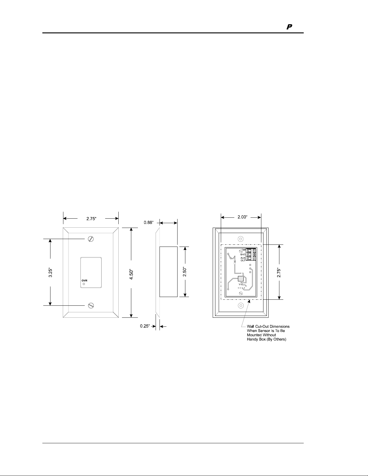
Section 2 Auto-Zone Plus
Sensors
Room Sensors
The Room Sensor uses a patented flush mount design to isolate the temperature sensing
element from the housing which mounts flush with the wall surface.
Room Sensors should be located on an inside wall away from direct sunlight or heat
producing equipment such as computers, copiers, etc. Such devices can adversely affect
the accuracy of the sensor. Although the sensor eliminates most of the effects of thermal
coupling to the walls, try to avoid walls which retain large amounts of thermal energy
(such as marble or steel). Walls containing either cold or warm air currents should also be
avoided whenever possible. Avoid locating the sensor in dead air areas of a room. This
will result in slow response to temperature changes in the space.
Figure 2-26: Room Sensor Installation
Mount the sensor approximately 50-60 inches from the floor for best results. The Room
Sensor is designed to mount vertically in a standard 2 by 4 inch electrical box. The sensor
may be mounted directly into the drywall where electrical codes do not require low
voltage wiring to be enclosed in conduit. A template is supplied with the sensor to
facilitate cutting a hole of the correct size.
2-38 Design Guide
Page 71

Auto-Zone Plus Section 2
Tip: Be careful when cutting the hole for the sensor or the plastic bezel of the sensor
may not completely cover the opening.
Tip: If sensors must be installed on walls which are solid and cannot be penetrated,
surface mounted boxes and raceway can be purchased from your local electrical
distributor.
Connect the terminal labeled GND on the room sensor to the terminal labeled GND on
the Zone Controller terminal block for the TEMP SENSOR. See Figure 2-27. Connect
the terminal labeled TMP on the room sensor to the terminal labeled TEMP on the Zone
Controller terminal block for the TEMP SENSOR. If the room sensor has a setpoint
adjust slider, connect the sensor terminal labeled AUX to the Zone Controller AUX
terminal block labeled AUX1.
ZoneController
Room Sensor
W
A
R
M
E
R
C
O
O
OVR
L
E
R
TMP
GND
AUX
Connection To AUX
Terminal Required Only
When SensorIs Specified
With Slide Adjust Option
AUX
+VS
AUX1
AUX2
GND
TEMP
GND
TB1TB1
++
TB2
Figure 2-27: Room Sensor to Zone Controller Wiring
Connect the terminal labeled GND on the room sensor to the terminal labeled GND on
the CV Controller terminal block for the TEMP SENSOR. See Figure 2-28. Connect the
terminal labeled TMP on the room sensor to the terminal labeled AIN1 on the CV
Controller terminal block for the TEMP SENSOR. If the room sensor has a setpoint
adjust slider, connect the sensor terminal labeled AUX to the CV Controller AUX
terminal block labeled AIN2.
Figure 2-28: Room Sensor to CV Controller Wiring
Design Guide 2-39
Page 72

Section 2 Auto-Zone Plus
Supply Air Temperature Sensor
The supply air temperature sensor should be located as close to the rooftop unit
discharge as possible for best response. It should also be mounted upstream of the bypass
damper for best results. Locate the sensor in the center of the widest part of the duct. Use
the supplied template and a 5/16" drill to make a hole for the sensor. Install the gasket
over the probe and mount securely to the duct using the supplied sheet metal screws. Be
sure the gasket is compressed to provide an air tight seal. For best accuracy, apply
insulation on the outside of the duct, over the sensor. This will help prevent thermal
gradients from affecting the sensor.
Leads Are Non-polarized.
Butt Splice Leads To 24 Gauge
Wire Minimum. Connect Leads
To "Analog In" And "Ground"
At Controller.
4.0"
Thread
Together
5-1/2" (OE230)
11-1/2" (OE231)
3/4"
Mounting Plate
1/4" Hex Head Sheet Metal Screws
Mounting Plate
Gasket
Adhesive Backed Drill Guide
Mounting Template
Duct Work
Drill 5/16" Hole In Ductwork For Probe
Figure 2-29: Supply or Return Air Sensor Installation
Return Air Temperature Sensor
The return air temperature sensor should be located as close to the rooftop unit return
air intake as possible. Avoid locations which will be exposed to extreme outside
temperatures. Locate the sensor in the center of the widest part of the duct. Use the
supplied template and a 5/16" drill to make a hole for the sensor. Install the gasket over
the probe and mount securely to the duct using the supplied sheet metal screws. Be sure
the gasket is compressed to provide an air tight seal. For best accuracy, apply insulation
on the outside of the duct, over the sensor. This will help prevent thermal gradients from
affecting the sensor.
Caution: Do not mount the return air sensor in the mixed air section. This will
cause an error in the reading.
2-40 Design Guide
Page 73

Auto-Zone Plus Section 2
Outside Air Temperature Sensor
The outside air sensor must be located where it will not be affected by direct sun or heat
producing equipment. Mounting under the eve of a roof is often a good choice.
Caution: Complaints of inaccurate outside sensor readings are very common and
can almost always be shown to be the result of poor sensor location
Note: All sensors utilize the same type thermistor sensor element. For troubleshooting
sensor problems refer to temperature sensor resetting instructions in Section 3 of
this manual.
Gasketed Cover
CAUTION!
See Note3
3.00”
Cover
Mounting
Screw -Typ.
2.30”
2.70”
ClosurePlug
CAUTION!
See Note 2
0.21" Dia. x 0.73
Lg. Slot -Typ.
4.50”
3.00”
Front View Side View
Notes:
1.)The Outside Air SensorMust Be
Mounted In AVertical Position As
Shown (SensorTube Pointing
Down).
Water Must Not Be
Allowed To Stand In Sensor
Tube. Rainwater Will Damage
Sensor.
SensorMust Be Located
Where ItWill Not Be Affected By
Direct Sunlig
Equipment.IfPossible Mount Under
RoofEaveOr Similar Protected
Location.IfSensorIs Not Located
As Specified, Erroneous Outside Air
Temperature ReadingsWill Result.
ht OrHeat Producing
2.25”
1.13”
SensorTube
CAUTION!
See Note 1
2.)Unused Conduit Opening(s) Must
HaveClosurePlugs
Be Coated with Sealing Compound To
Provide Raintight Seal. Water Can
Damage Sensor!
3.)Gasket Must Be Installed Under Cover
Plate ToProvide Raintight Seal.
Rainwater Can Damage Sensor!
4.)All WiringToBeIn Accordance With
LocalAnd NationalElectrical Codes
And Specifications.
MountingTab
&Screw -Typ.
Installed And Must
ClosurePlug
CAUTION!
See Note 2
BackView
Incorrect
See Note #1
Incorrect
SensorMounting
Correct
Postion
MountingTab
&Screws -Typ.
Figure 2-30: Outside Air Temperature Sensor
Design Guide 2-41
Page 74

Section 2 Auto-Zone Plus
.
Duct Static Pressure Sensor
The duct static pressure sensor is designed to be mounted at the controller, or on the
ductwork near the pickup tube, and may be connected via its modular plug. If the
sensor is mounted on the ductwork, the modular plug must be cut off and 3-conductor
wire spliced onto the sensor leads. If the trunk ducts are properly sized for minimum
pressure drop, the location of the static pickup probe is not particularly critical. It
should ideally be located at right angles to the airflow in a straight section of the supply
duct approximately 2/3 the distance of the total length of the supply duct. Also the
probe should be located not less than 3 duct diameters downstream and 2 duct
diameters upstream of any elbow or takeoff. See Figure 1-3 in Section 1 of this
manual for general mounting location information.
"
0
0
.
"
1
5
5
.
0
1.95"
OE271
0.60"
0.200" (3/16" Tubing Conn.)
0.125" (1/8" Tubing Conn.)
(-)LO
S.P. Sensor
0.15" DIA.
12.0" APPROX
OUT (Black)
GND (Green)
OUT
GND
2.20"
2.50"
IN (Red)
UP
IN
0.15"
1.29"
2.94"
0.35"
Figure 2-31: Duct Static Pressure Sensor Dimensions
Caution: Mount the static pressure sensor on a vertical surface with the tube tips
pointing downward. Avoid any kinks or sharp bends in the tubing which
runs from the pickup tube to the sensor.
Warning: The plastic housing on the sensor is electrically conductive. Avoid
contact with any electrical components. It is acceptable to mount the
sensor on grounded sheet metal such as ductwork, electrical panels,
etc.
2-42 Design Guide
Page 75

Auto-Zone Plus Section 2
Warning: Use extreme care when mounting the sensor to avoid damage to the
plastic housing. Do not over tighten the mounting screws! Do not use
mounting screws which are too large for the holes!
Tip: Having at least 10-20 feet of tubing between the pick-up tube and the pressure
sensor will improve control performance by acting as a “filter” to remove
pressure fluctuations caused by turbulence in the duct.
Figure 2-32: Static Pressure Sensor Wiring
Note: Refer to Figure 1-4 in section 1 of this manual for instructions concerning
proper location of the static pressure sensor.
Design Guide 2-43
Page 76

Section 2 Auto-Zone Plus
CommLink IV
General
The CommLink IV is used to transfer communications between controllers on your
control system loops. It can also be used as an interface for connection of a computer to
your system. The CommLink IV provides communication with any controller on the
control system through a computer that is running Prism software or it can be used to
communicate with most controllers by using only the System Manager. For remote
communications, an IP Module Kit can be installed for LAN and Internet connections or
a Remote Link II can be connected for dial-up connections.
STATUS
Optional IP Module Kit
The OE415-02 IP Module Kit, when installed and configured in the CommLink IV
communication interface, provides TCP/IP Internet and/or intranet connection for
Ethernet networked computer systems allowing them to communicate with your
control system.
The OE415-02 IP Module Kit consists of the IP Module and a 10 ft. long CAT5 Ethernet
crossover cable. Using standard TCP/IP Protocol, with WattMaster’s Prism software, you
are able to monitor and configure your controllers without a modem or a direct
connection from a PC. Utilizing existing routers, proxies, or firewalls allows a PC
running Prism to connect to a controller in a remote accessible location or building.
Several IP connection profiles can be created to facilitate monitoring several CommLink
IVs with IP Module Kits installed on individual sites. See the IP-Module Technical Guide
Form: WM-IPM-TGD for complete product details and installation instructions.
2-44 Design Guide
Page 77

Auto-Zone Plus Section 2
Optional Remote Link II
The OE419-06 Remote Link II is a 14,400 baud modem that can be used with a
CommLink IV or a computer. It is used to provide remote dial-up communications with
the CommLink IV. When it is used as a computer modem (at the remote computer
location), it connects to the remote computer.
Note: WattMaster will not support any other internal or external modems by other
manufacturers.
The Remote Link connects to the CommLink IV communications interface at the control
system location via a DB9 serial cable. A telephone line connects the Remote Link to the
local phone service. Using another Remote Link modem connected to a computer and
phone service at a remote location, you can monitor and control the system using the
Prism computer front end software. Connection is made by dialing the telephone number
of the job site where the Remote Link is located. See the Remote Link II Technical Guide
Form: WM-RLII-TGD for complete product details and installation instructions.
Design Guide 2-45
Page 78

Section 2 Auto-Zone Plus
C
CommLink IV Wiring
ommLink IV
Communications Interface
Serial #
GND
24V
POWER
Optional Items Not
Required For
DIAG
10/100
ETHERNET
ACT LNK
USB Switch
Should Be Set
To Normal
COMPUTER
USB
Normal
Config
USB
MODEM
RS-232
Female
TGR
485 LOOP
9 Pin
CommLink Only
Installations
Optional - Prefabricated Ft. Long CAT5
Ethernet Cable (Included With Optional OE41502 IP Module Kit).
Ethernet Router On Your LAN.
Ethernet Cable Is Required, You Will Need To
Obtain (From Others) And Install An Ethernet
Cable Of The Required Length For Your
Installation.
.
USB Cable (Included). Connect
This Cable To Your Computer USB
Port For Directly Connecting To
CommLink IV. Also Used For
Advanced Configuration of
CommLink IV.
Molded Modem Cable.
Part #HZ000098
Supplied With RemoteLink II
10
Connect To A 10/100 Base-T
If A Longer
25 Pin
Male
When An Optional Remote
Link Is Used, Connect This
Cable To CommLink IV And
Remote Link As Shown. Cable
Is Included With Remote Link.
Connect To The
Zone Manager MiniLink
See Note 1
120 to 24 VAC Power Pack
(Included) Connect To 120/1/60 Duplex
Receptacle (By Others)
If Desired A 24 VAC Transformer
Included)
Used Instead Of The Supplied Power Pack.
Use 18 Gauge Minimum 2 Conductor Wire
Between The Transformer & CommLink IV
Te rm in a ls
WARNING!
With Your CommLink, Do Not Have Your
Ethernet Connection And USB Connection
Connected At The Same Time. This Could
Cause Unreliable Communications.
Notes:
1) Use 18 Gauge Minimum 2 Conductor Twisted Pair With Shield Cable Belden #82760 Or Equivalent
(Not Included) To Connect The CommLink IV To The Zone Manager MiniLink.
2) For Direct Connection Via USB, Your Computer Must Have An Unused USB Port Available. Drivers
For Your USB Port Are Provided On A CD Supplied With The CommLink IV And Will Need To Be
Installed On Your Computer In Order For It To Function Correctly. Please Follow The Directions In
The CommLink IV USB Driver Installation Section (Included) To Install And Configure The USB
Drivers.
3) The CommLink IV Cannot Communicate With The Control System Through Its Ethernet Port And
USB Port At The Same Time.
4) All Wiring Must Conform To Applicable Federal, State & Local Electrical Wiring Codes.
24 VAC Power
18 Gauge 2 Conductor
With Shield (Not Included)
See Note 1
Rated At 12 VA Minimum May Be
(Not
If You Are Using The IP Module
Figure 2-33: CommLink IV Wiring
2-46 Design Guide
Page 79

Auto-Zone Plus Section 2
q
p
CommLink IV DIP Switch Setting
CommLink IV Communication Settings
The SW1 DIP Switch Located On The Circuit Board Inside
The CommLink IV Housing Must Be Set Correctly For
Your Specific Application In Order To Function Properly.
The CommLink IV Is Factory Set For Multiple Loop
Applications.
To Check And/Or Set The SW1 Dip Switch, First Remove
The (2) Enclosure Screws That Hold The Top And Bottom
Of The CommLink IV Enclosure Together. Remove The
Top Half Of The Enclosure To Access The Circuit Board
And Dip Switches.
The DIP Switch Setting Should Be Set To “Multiple”
SW1
For The Auto-Zone Plus System
Replace The CommLink IV Cover And Secure The
Enclosure Halves Back Together With The (2) Enclosure
Screws That Were Previously Removed.
WattMaster Controls Inc.
COMMLINK IV
YS102074
REV6
MADE IN USA
ALTERA
EPM3032
DIP Switch 1 & 2 Off =
Multiple Loop Communications
uired Setting For Auto-Zone Plus System
Re
Figure 2-34: CommLink IV DIP Switch Setting
USB
CLOSE
LOOP
LOCAL
LOOP
MODEM
RS-232
1
2
4
8
16
32
S
W
1
1
B
4
2
C
A
8
6
DIAG
10/100
ETHERNET
USB
ACT LNK
Network
Comm Loop
FDBK
GND
OPEN
CLOSE
V3
V4
T
SHIELD
R
R
FAN
COOL1
COOL2
HEAT1
HEAT2
T
SHIELD
R
Local
Comm Loo
COMPUTER
Normal
Config
K
2
T
SH
R
NETWORK
T
SH
R
TGR
485 LOOP
T
A
D
D
Local Communications Loop
To Zone Controllers
And System Manager
Serial #
GND
24V
POWER
R
SHIELD
ANALOG
OUTPUTS
A1
A2
G
TB2
COMM
T
SH
R
TB3
Figure 2-35: CommLink IV to Zone Manager Wiring
Design Guide 2-47
Page 80

Section 2 Auto-Zone Plus
Installing the CommLink IV
When you are using the CommLink IV with the Auto-Zone Plus System and are not
going to use a Computer, Remote Link II, or IP Module, you only need to perform three
steps to install your CommLink IV.
Step #1: Check and make sure your CommLink’s communication switch is set to
Multiple. See Figure 2-34 for details on setting the DIP Switch on the CommLink IV.
Step #2: Install communications wiring (18 ga. minimum 2 conductor twisted pair with
shield) from the CommLink IV to a Zone Manager on your controls system. The
communication wiring should connect from the T, G & R terminals on the CommLink IV
to the network T, SH & R terminals of the MiniLink mounted on top of one of the Zone
Managers on your controls system. See Figure 2-35. Be sure that you wire the
CommLink “T” terminal to the MiniLink “T” terminal, The CommLink “G” Terminal to
the MiniLink “SH” terminal and from the CommLink “R” terminal to the MiniLink “R”
terminal as shown.
Step #3: Wire the supplied 120/24 VAC power pack to the 24 VAC and GND terminals
on the CommLink IV. Plug the power pack into a standard 120 VAC duplex outlet.
If you intend to use a Computer, Remote Link II, or IP Module, in addition to the steps
just performed you will need to perform additional installation procedures. Please refer to
the CommLink IV Installation Technical Guide Form: WM-CLIV-TGD which is supplied
with the CommLink IV. It will instruct you regarding installation and troubleshooting of
the CommLink when an optional personal computer and/or other communication devices
are used. This manual is also available from any of the WattMaster websites for
downloading as are the USB drivers and Prism Software which are required for
installation when using the optional personal computer or other communication devices.
2-48 Design Guide
Page 81

Auto-Zone Plus Section 2
System Manager
The OE392 System Manager System Operator Interface provides a direct link to enable
the system operator to view the status and to adjust the setpoints of any Zone Manager,
Zone Controller or CV Controller on the Auto-Zone Plus system communications loop.
The System Manager is housed in an attractive beige colored plastic enclosure with white
and green accents. The System Manager is equipped with a four line by 20 character
backlighted display panel and a 20 key membrane keypad for data selection and entry. All
keypad operations are simple and straight forward, utilizing non-cryptic plain English
language messages. Menu driven programming allows for easy setup and operation
without the need for specialized training. The System Manager also has two integral
LED’s for user notification of system communication and alarm conditions. Protection
from unauthorized users is provided by the System Manager’s integral multi-level
passcode authorization programming.
The System Manager is designed for wall mounting. It is recommended that the System
Manager be mounted at approximately eye level to allow for ease of programming and
reading of the display. The System Manager is typically mounted in the building manager
or superintendent’s office or in an equipment room. The enclosure is quite suitable for
mounting in any location or with most decor.
9.00
6.25
Membrane
Keypad
Four Line by 20 Character
Backlighted Display
Figure 2-36: System Manager Dimensional Data
1.90
Design Guide 2-49
Page 82

Section 2 Auto-Zone Plus
System Manager Wiring
The System Manager can be connected anywhere on the Plus system local
communications loop. Do Not Connect the System Manager to the Plus System
Network Loop! The system will not function if the System Manager is connected to the
network loop. The System Manager must also be connected to 24 VAC in order to
operate. See Figure 2-37 for System Manager wiring.
Figure 2-37: System Manager Wiring
2-50 Design Guide
Page 83

Auto-Zone Plus Section 2
Index:
14,400 Baud Modem........................... 45
24VAC-to-24VAC.................. 22, 31, 35
90% RH............................................... 33
Above 140° F ...................................... 33
Actuator Cable .................................... 17
Actuator Clutch................................... 17
Add-on Controllers
Addressing ...................................... 14
Address Switch
Zone Controller............................... 23
Address Switch Setting
CV Controller.................................. 32
CV-C Controller.............................. 37
Addressing
Add-on Controllers ......................... 14
CV Controllers.......................... 14, 32
CV-C Controllers...................... 14, 37
MiniLink ......................................... 11
Zone Controllers ....................... 14, 23
Zone Manager ................................. 11
AUX.................................................... 39
Aux Heat Relay................................... 27
AUX1.................................................. 39
Auxiliary Heat..................................... 25
Auxiliary Relay
Operation Sequence ........................ 27
Auxiliary Relay Board
Layout ............................................. 25
Wiring ............................................. 26
Zone Controllers ............................. 25
Backplate
Mounting......................................... 13
Belden #82760 cable........................... 14
Below 20° F ........................................ 33
Box Heat ............................................. 25
Box Heat Relay ................................... 27
Bypass Damper
Wiring ............................................. 18
Bypass Dampers
Installing.......................................... 16
Mounting......................................... 16
Bypass Wiring Interface Board ........... 16
Wiring ............................................. 17
Cable
Belden #82760 ................................ 14
WattMaster...................................... 14
CommLink IV
Connecting to Zone Manager.......... 47
Description...................................... 44
Dip Switch Setting .......................... 47
Installation....................................... 48
Installing.......................................... 46
Wiring ............................................. 46
Communication Problems
Incorrect Addressing....................... 23
Communications Loops ...................... 14
Components
CV Controller.................................. 29
Zone Controller............................... 21
Conductors
Voltage............................................ 13
Conduit................................................ 15
CV Controller
Addressing ................................ 14, 32
Components .................................... 29
Dimensions ..................................... 28
Electrical Connections .................... 31
Environmental Limitations ............. 28
Installing.......................................... 28
Mounting......................................... 28
Wiring ............................................. 30
CV-C Controller
Addressing ................................ 14, 37
Dimensions ..................................... 33
Electrical Connections .................... 36
Environmental limitations............... 33
Installing.......................................... 33
Mounting......................................... 33
Prism requirement........................... 33
Wiring ............................................. 34
CV-C Expansion Board
Wiring ............................................. 35
Daisy Chain......................................... 14
Design Guide 2-51
Page 84

Section 2 Auto-Zone Plus
Damp or Wet Environments ............... 33
Damper Actuator........................... 16, 17
Damper Blade ..................................... 17
DB9 Serial Cable ................................ 45
Dial-up Communications.................... 45
Dial-up Connections ........................... 44
Dimensions
CV Controller.................................. 28
CV-C Controller.............................. 33
Duct Static Pressure Sensor ............ 42
System Manager.............................. 49
Drywall................................................ 38
Duct Static Pressure Sensor ................ 42
Dimensions ..................................... 42
Installing.......................................... 42
Mounting......................................... 42
Electrical Connections
CV Controller.................................. 31
CV-C Controller.............................. 36
Zone Controller............................... 22
Zone Manager ................................. 13
Electrical Short.................................... 15
Energy Efficiency
Improving........................................ 16
Environmental Limitations
CV-C Controller.............................. 33
Expansion Board
Jumper Settings............................... 12
Wiring ............................................. 12
Extreme High Temperatures ............... 33
Extreme Low Temperatures................ 33
GND.................................................... 39
GND-to-GND ......................... 22, 31, 35
Inaccurate Outside Sensor Readings... 41
Incorrect Addressing........................... 23
Incorrect Wiring.................................. 14
Installation Tips .................................... 5
Intranet Connection............................. 44
IP Module Kit ..................................... 44
Desribed .......................................... 44
LAN and Internet Connections ........... 44
Local Loops..................................... 5, 14
Metal Shavings.............................. 31, 36
MiniLink
Addressing ...................................... 11
Modulating Box Heat.......................... 27
Modulating Hot Water Valve.............. 27
Network Loop ................................. 5, 14
OE322 Expansion Board..................... 27
OE351 Relay Expansion Board .......... 36
OE352 Expansion Base Board............ 12
OE355 4 Analog Output
Expansion Board....................... 12, 13
OE357 4 Relay Expansion Board ....... 13
OE357 Relay Output Expansion
Board............................................... 12
OE392 System Manager ..................... 49
OE415-02 IP Module Kit.................... 44
OE419-06 Remote Link II .................. 45
Outside Air Temperature Sensor......... 41
Installing.......................................... 41
Mounting......................................... 41
Parallel Fan ......................................... 25
Parallel Fan Relay ............................... 27
Plastic Bezel........................................ 39
Plastic Housing ................................... 43
Plus System Overview
Diagram............................................. 6
Polarity................................ 5, 22, 31, 35
Power
Recycling .................................. 23, 25
Prism ................................................... 44
Rectangular Damper shaft................... 16
Recycling Power ........................... 23, 25
Relay #1 - Parallel Fan........................ 27
Relay #2 - Box Heat............................ 27
Relay #3 - Aux Heat............................ 27
Relay #4 - Series Fan .......................... 27
Relay Contacts .................................... 25
Remote Link II.................................... 44
Described ........................................ 45
Requirements
Electrical, CV Controller ................ 31
Return Air Temperature Sensor
Installing.......................................... 40
Mounting......................................... 40
Rooftop Unit
Discharge ........................................ 40
Return Air Intake ............................ 40
2-52 Design Guide
Page 85

Auto-Zone Plus Section 2
Room Sensor
Wiring ............................................. 39
Room Sensors
Installing.......................................... 38
Mounting......................................... 38
Round Zone Damper........................... 19
SAT
Sensor.............................................. 40
SCR Electric Heating Coil.................. 27
Sensors
OAT ................................................ 41
RAT................................................. 40
SAT................................................. 40
Sequence of Operation
Auxiliary Relay............................... 27
Series Fan............................................ 25
Series Fan Relay.................................. 27
Setpoint Adjust Slider......................... 39
Slaved Dampers ............................ 16, 19
Slaved Zone Controller
Wiring ............................................. 24
Star Configuration............................... 15
Static Pressure Sensor
Wiring ............................................. 43
Supply Air Temperature Sensor.......... 40
Installing.......................................... 40
Mounting......................................... 40
Sweating
Prevention ................................. 16, 19
System Manager
Described ........................................ 49
Dimensions ..................................... 49
Wiring ............................................. 50
TCP/IP Internet ................................... 44
TEMP SENSOR ................................. 39
Temperatures
Extreme High .................................. 33
Extreme Low................................... 33
Terminal Blocks
Unplugging...................................... 22
Thermistor Sensor............................... 41
TMP .................................................... 39
WattMaster
Communication Cable .................... 14
Weathertight Enclosure
CV Controller.................................. 28
Wire
Requirements .................................. 13
Wiring
Incorrect .......................................... 14
Wiring
Auxiliary Relay Board .................... 26
Bypass Damper ............................... 18
Bypass Wiring Interface Board ....... 17
CommLink IV................................. 46
CV Controller.................................. 30
CV-C Controller.............................. 34
CV-C Expansion Board .................. 35
Expansion Board............................. 12
Room Sensor................................... 39
Slaved Zone Controllers ................. 24
System Manager.............................. 50
Zone Controller............................... 23
Zone Manager ................................. 10
Zone Controller
Address Switch ............................... 23
Addressing ................................ 14, 23
Auxiliary Relay Board .................... 25
Components .................................... 21
Electrical connections ..................... 22
Installing.......................................... 20
Mounting......................................... 20
Serviceability .................................. 20
Slaved.............................................. 24
Wiring ............................................. 23
Zone Controller Address Switches
When to Set....................................... 5
Zone Dampers
Installing.......................................... 19
Mounting......................................... 19
Zone Manager
Addressing ...................................... 11
Components ...................................... 9
Dimensions ....................................... 8
Electrical Connection Requirements13
Installing............................................ 8
Mounting........................................... 8
Wiring ............................................. 10
Design Guide 2-53
Page 86

Section 2 Auto-Zone Plus
2-54 Design Guide
Page 87

Auto-Zone Plus Section 3
Table of Contents
LCD/Keypad Operations................................................... 3
System Manager Layout...................................................................................................4
View Alarms Screen ........................................................ 6
Full System Access ......................................................... 7
Keypad Functions ............................................................................................................7
System Manager LED Indicators .....................................................................................8
Set Time & Date ..............................................................8
New Passcodes................................................................ 9
Rebuild Alarm Map......................................................... 10
Read / Reset Units .........................................................11
Zone Manager Read/Reset Operations ......................... 12
Zone Manager Status .................................................... 13
Zone Manager Configuration ......................................... 16
Zone Manager Setpoints ............................................... 21
Control Setpoints ...........................................................................................................21
Zone Manager & CV AHU Force Modes......................... 28
Zone Controller Read/Reset Operations ....................... 30
Individual Zone Status Screens .................................... 30
Zone Controller Setpoints ............................................. 33
Zone Controller Force Modes ........................................ 37
CV Read/Reset Operations ............................................38
Constant Volume AHU Status ....................................... 39
Constant Volume AHU Setpoints .................................. 42
Zone Manager Scheduling, Holidays and Optimal Start49
Week Schedules .............................................................................................................49
Holidays .........................................................................................................................50
Optimal Start..................................................................................................................51
CV AHU Scheduling and Holidays ................................. 52
Week Schedules .............................................................................................................52
Holidays .........................................................................................................................53
Wetbulb Module Read/Reset Operations...................... 54
LCD/Keypad Operations Summary ................................ 56
Programming 3-1
Page 88

Section 3 Auto-Zone Plus
3-2 Programming
Page 89

Auto-Zone Plus Section 3
LCD/Keypad Operations
Main Screen
v1.xx
Monday Operations
03/24/02 09:46 AM
Outdoor Air 78.0°F
The Auto-Zone System Manager is your direct link to the status and setpoints of any
Auto-Zone component on your communications loop. With the System Manager, you can
view any temperature or output condition and change any setpoint to fine tune the
operations of the total system. All keypad operations are simple and straight-forward,
utilizing non-cryptic plain English messages. The System Manager automatically detects
the type of unit that has been selected, and displays the appropriate status and setpoint
screens. The attractive plastic case of the System Manager allows for placement in any
area of your building.
The remainder of this document will lead the user through the system menus and keypad
operation.
All user functions are accessed by pressing the Menu button. Once the button is pressed,
the Main User Menu is displayed.
Programming 3-3
Page 90

Section 3 Auto-Zone Plus
System Manager Layout
1.90
9.00
6.25
Main User Menu
1) View/Change Zone
2) View Alarms
MENU) Full Access
ESC) Main Screen
Four Line by 20 Character
Backlighted Display
1) View/Change
Zone
2) View Alarms
MENU) Full
Access
ESC) Main
Screen
Membrane
Keypad
For quick access to an individual zone,
select this menu item. Any Zone or
Constant Volume unit can be selected.
The user can view the room
temperature and change the current
cooling and heating setpoints. You
must be at least a Level 1 user to
change the setpoints.
If the System Manager has been
configured for Alarm Polling, the user
can select this item to get a list of unit
addresses that are currently in alarm. If
an alarm exists, the Alarm LED will
be active on the right side of the panel.
If you are a Level 2 user, the full system
Read/Reset capabilities are available to
you. These capabilites are accessed via
this Menu button.
When you have finished viewing the
system you can exit this menu and return
to the Main Screen by pressing the ESC
button.
3-4 Programming
Page 91

Auto-Zone Plus Section 3
View/Change Zone
View/Change
[ Enter Unit ID# ]
Selected Unit: 101
If you have selected the View/Change Zone menu item, you
will be allowed to view any selected zone temperature and
its current cooling and heating setpoints. If you are at least a
Level 1 user, you can also change the cooling and heating
setpoints from this screen. The first screen that appears,
prompts you for the Unit ID you wish to view. The Unit ID
is actually two separate numbers, combined into one value.
The first part of the number contains the Loop Address at
which the zone is located. The second part of the number
contains the actual Board Address.
EXAMPLE: You would like to view the 3rd zone on the
You would like to view the 12th zone on the
Zone Controller Status
Zone Controller
Temperature: 75.4°F
Cooling SP.: 75°F
Heating SP.: 72°F
If the selected Unit ID is correct, and the unit responds, one of
the following screens will appear. If you are a Level 1 user, you
can select either the Cooling or the Heating setpoint with the
Up/Down Arrow keys. To change the setpoint, use the
Left/Right Arrow keys. The setpoints are fully adjustable
between their normal limits of 50 to 90 degrees. When you are
finished viewing this screen, simply press the ESC button to
exit.
5th loop. Enter 503 as the Unit ID
24th loop. Enter 2412 as the Unit ID
Constant Volume Unit
Constant Volume Unit
Temperature: 75.4°F
Cooling SP.: 75°F
Heating SP.: 72°F
Programming 3-5
The Heating Setpoint is never allowed to get any closer than
two degrees of the Cooling setpoint on Zone Controllers and
one degree on Constant Volume Units. If you are lowering the
Cooling setpoint or raising the Heating setpoint, both values
will be kept apart automatically by the correct amount.
Page 92

Section 3 Auto-Zone Plus
Entering Passcodes
THIS ACTION REQUIRES
PASSCODE CLEARANCE
Enter Passcode: xxxx
Anytime you are prompted to enter a passcode, the following
screen will appear. No reference is made as to the level of
passcode to enter, but if you attempt to access a Level 2
function with a Level 1 passcode, the system will prompt you
to enter the correct passcode again.
View Alarms Screen
Alarm Address Locations
SYSTEM ALARM STATUS
Alarm @ Unit ID 118
The System Manager can be programmed to poll all the AutoZone units on your system for alarm information. This allows
the centrally located System Manager to display an Alarm
Indicator whenever an alarm condition exists anywhere on your
system. The actual alarms are not displayed on this screen, only
the Unit ID where the alarm is located. The example shows that
a unit at location 118 has experienced an alarm condition. This
alarm may or may not be current, as the System Manager
latches the alarm condition. This makes it possible to determine
if any intermittent alarm conditions have occured. If you have
Level 2 access, you can enter the full system access mode,
select that unit for display, and determine what the exact alarm
condition is for that unit. The alarm conditions are always
displayed on the Status Screens.
Alarm Clearing
SYSTEM ALARM STATUS
Clear Alarms? YES
To Change Response
Use Left/Right Arrow
3-6 Programming
If all the alarm conditions have been corrected at the individual
units, you can clear these alarms from the System Manager on
the following screen. Use the Left/Right arrow keys to select
the YES/NO response desired. If you clear the alarms, but
some still exist, the System Manager will show an alarm
indication, when the affected unit is polled again.
Page 93
Auto-Zone Plus Section 3
Full System Access
Full Access Menu
1) Set Time & Date
2) Read/Reset Units
3) New Passcodes
4) Rebuild Alarm Map
If you selected the MENU key from the first menu screen you
can gain full system access. However, you must be a Level 2
user. If you haven't already been asked to enter the passcode,
you will be asked before the Full Access Menu is displayed.
This prevents the casual user from being overwhelmed with the
full amount of data and setpoints available to the Level 2 user.
Keypad Functions
The System Manager keypad is labeled either numerically or as to actual function for that
key. Below is a summary of the labeled keys and their functions.
MENU This key is used to gain access to the first menu, and the user will be
notified, on the LCD, if any subsequent use of the key will be
required for further access.
ESC The ESCape key allows the user to abort what he/she is doing or exit
back to previous menus. Also, anytime you want to leave the system
unattended you should press the ESC key until the Main Screen
appears.
CLEAR If you make a mistake while entering setpoint data, you can clear the
bad data from the display by pressing the Clear key.
ENTER Use the Enter key to close out a data entry. It can also be used to
advance to the next field or screen.
DEC If entering a setpoint that requires a decimal point, press this key
where the decimal is located while entering the value.
MINUS If you need to enter a negative value, you must press the Minus key
before entering the digits for that value.
UP/DOWN
Arrows
LEFT/RIGHT
Arrows
Use these keys to step forward or backward through Status Screens or
Setpoint Data Fields.
If the screen prompts you to use these keys, it is used normally to
toggle modes of operation. In some cases they may be used for other
functions and the user will be prompted as to what these might be.
Programming 3-7
Page 94

Section 3 Auto-Zone Plus
System Manager LED Indicators
There are two LED indicators located on the right hand side of the System Manager.
The top LED labeled “Alarm” indicates an Alarm condition if the Manager detects an
alarm condition while polling the system.
The bottom LED labeled “Communication” is active during actual communications or
packet transfers. This LED will normally "flicker" and not remain on constantly.
Set Time & Date
The System Manager has its own built in Real Time Clock. It broadcasts this time once a
day, at midnight, to synchronize all the other units on your Auto-Zone system. Although
the times are displayed on the Main Screen in a standard 12-hour format, they are
programmed using the 24-hour Military format. Once the time has been entered, it is also
broadcast immediately to all other units on the system. That means that you only need to
program the System Manager time to set the Real Time Clocks for all units on your
communications loop.
Programming Time
Program Time/Date
Day (Sunday=0): 1
Enter Hr. (0-23): 9
Enter Minutes : 53
Day
Hours (Hr)
Minutes
Programming Date
Program Time/Date
Month (1-12): 9
Day (1-31): 18
Year (00-99): 95
Month
Day
Year
- Enter the Day of the Week (0 to 6) with
Sunday = 0
- Enter Hours in 24-Hour Military Format
(1700 = 5:00 PM)
Enter the Minutes (0 to 59)
-
- Enter the Month (1 to 12)
Enter the Day of the Month (1 to 31)
-
-
Enter the current Year with 2 digits (00 to
99)
3-8 Programming
Page 95

Auto-Zone Plus Section 3
Daylight Savings Adjustments
Daylight Savings
Auto Adjustments: YES
Use Left/Right Arrow
If your area of the country requires Daylight Savings changes, you
can enable the System Manager to automatically reset its own
clock during the Daylight Savings changeover. However, if you
enable this operation, be aware it will changeover the first Sunday
in April and then switch back the last Sunday in October. These
used to be the standard dates every year that were constant from
year to year.
The U.S. government has seen fit recently to arbitrarily determine
the switch over dates each year so it is recommended that you
disable this function and manually change the schedules from year
to year.
Use the Left or Right arrow keys to toggle the second line of the
display between Adjustments Enabled and Adjustments Disabled.
New Passcodes
Programming Passcodes
Enter New Passcode
Level 1.....: XXXX
Level 2.....: XXXX
[Must Be 4 Digits]
Caution: If you change the Level 2 passcode and cannot remember what it is, you
will be locked out of your system!
The System Manager has two levels of user access.
Level 1 users are limited to viewing or changing Zone
Temperatures and their Heating and Cooling Setpoints, and to
viewing Unit ID numbers for those in alarm conditions.
Level 2 users have complete system access. Any status or
setpoint field can be read or reset from the Auto-Zone system.
These two levels of passcodes are programmable by any Level
2 user. The default Level 1 passcode is "1111" and the default
Level 2 passcode is "2222."
The actual digits in your passcodes are never displayed. An "X"
is used as a place holder for each digit entered. Passcodes must
always be four digits in length, so the useable range of numbers
is 1000 to 9999.
Programming 3-9
Page 96

Section 3 Auto-Zone Plus
Rebuild Alarm Map
Rebuilding Screens
Clearing Old Map
....................
................
Build New Map?
[ESC = NO]
Building New Map
Loop: 1 Unit: 1
Dec) Go To Next Loop
ESC) Abort Process
Alarm Unit Map Built
Press Any Key To
Continue
If you would like the LED Alarm Indicator to function on the
front of your System Manager, you must enable Alarm Polling
by building an Alarm Map. This map keeps track of which
units exist on your communications loop so the System
Manager will poll only those units. That means you will need
to rebuild this map anytime units are added or removed from
your system. It also means you can disable alarm polling. To do
this, disconnect the RS-485 communications plug from the
back of your Comm Link IV. Then, select the Rebuild Alarm
Map menu. The System Manager will not find any units to poll
for alarms since none are connected. This is useful during
building startup, when you don't want nuisance alarms
bothering you.
The screen will display each address it is testing and if a unit
has been found at that address. If you know you only have two
loops on your system and you don't want to wait for it to test
the remaining twenty-eight loops, you can press the ESC key as
soon as Loop 3 is displayed and the test will conclude. All units
found up to that point will be saved in memory.
The System Manager does not rebuild this map automatically
on powerup! You must do this manually. This rebuild should
only be performed one time, when all units are up and running.
It is not a regular requirement. As mentioned above, only when
the number of units connected changes should the alarm map
be rebuilt.
3-10 Programming
Page 97

Auto-Zone Plus Section 3
Read / Reset Units
Read/Reset Address Entry
Read/Reset
[ Enter Unit ID# ]
Selected Unit: 101
You must know the Unit ID of the controller you wish to view.
This number is created by combining the Loop Address with
the controller Board Address. The Zone Controllers are always
addressed starting at one and continuing up to sixteen. The
Zone Manager is always at address seventeen and any Constant
Volume units would start at eighteen and continue to thirty. If
this is a Constant Volume only system, the address range of the
controllers would simply be one to thirty.
Example Unit ID Numbers:
Controller @ Loop 3, Board Address 1
Controller @ Loop 12, Board Address 14
Once you have finished the Read/Reset function, you can exit
this mode by pressing the ESC key. This will return you to the
Full Access Menu.
Unit ID = 301
Unit ID = 1214
Programming 3-11
Page 98

Section 3 Auto-Zone Plus
Zone Manager
Read/Reset Operations
If the Unit ID you entered was for a Zone Manager, the following menus will appear.
Zone Manager Menu #1
1) Manager Status
2) Change Setpoints
MENU) Next Menu
ESC) To Exit
1) Manager Status
2) Change Setpoints
MENU) Next Menu
Zone Manager Menu #2
1) Schedules
2) Configuration
3) Force Modes
MENU) Previous Menu
1) Schedules
2) Configuration
3) Force Modes
MENU) Previous Menu
View the current temperatures
and operating modes for this
Zone Manager.
View or change any of the
available setpoints for this
Zone Manager.
Access the next Menu Page for
the Zone Manager.
View or change any of the
Week Schedules or Holidays
for this Zone Manager.
View or change the operating
configuration of the Zone
Manager. These setpoints are
normally set one time and
never changed again. They
include parameters such as the
number of zones, or heating
and cooling stages, etc..
Select this menu to override
the currently scheduled
operating mode.
Return to the previous menu
shown above.
3-12 Programming
Page 99

Auto-Zone Plus Section 3
Zone Manager Status
Line 1 Displays the currently selected Zone Manager and its current operating software
version on all Status Screens shown below.
Status Screen #1
Manager # 1 vl.xx
Occupied Mode
Vent Mode
Line 2 -
Line 3 -
Line 4 -
Status Screen #2
Manager # 1 vl.xx
Supply Air: 78.6°F
Return Air: 77.3°F
Outdoor Air: 70.2°F
The Supply Air Temperature, Return Air Temperature and
Outdoor Air Temperature are displayed on this screen.
The Outdoor Air Temperature is either the onboard sensor
reading, or it can be the Global Broadcast value received from
another unit. Only one unit per system needs to have the
Outdoor Air Sensor installed.
Unoccupied Mode
Return Control
Occupied Mode
Push Button Override
Forced Occupied
Forced Unoccupied
Forced Fan Only Mode
Purge Mode
Neutral Mode
Vent Mode
Cooling Mode
Heating Mode
Binary Contact Alarm
Blank Line if no Alarm
Programming 3-13
Page 100

Section 3 Auto-Zone Plus
Status Screen #3
Manager # 1 vl.xx
Static Pr..: 0.49"
Bypass Dmpr: 18 %
Economizer.: 50 %
The Static Pressure, measured in Inches of Water Column, is
displayed along with the Bypass Damper or VFD Percentage
position currently being used to maintain that amount of static.
The last line shows the Economizer Damper position if your
system is configured for Economizer Control.
Status Screen #4
Manager # 1 vl.xx
Active Cool Stage: 0
Active Heat Stage: 0
Manager # 1 vl.xx
CW Valve ...: 0%
HW Valve ...: 0%
If you configured the Zone Manager for DX cooling the active
number of cooling stages will be displayed. If you also
configured the Zone Manager for Staged Heating the active
number of heating stages will be displayed also. There are a
maximum of six stages of heating and six stages of cooling
available, if the optional relay expansion board is used. If you
configured your Zone Manager for a Cooling Valve the percent
open position of the CW valve will be displayed. If you
configured the Zone Manager for HW valve the percent open
position of the HW valve will be displayed.
Status Screen #5
Manager # 1 vl.xx
Cool Total.: 0.0°F
Heat Total.: 0.0°F
Mavericks..: 0
As the Zone Manager polls its Zone Controllers, it totals up the
heating and cooling demand so it can make an HVAC decision.
The Cooling Total and Heating Total are displayed on this
screen.
The Zone Manager also knows if any units have had more than
a four degree demand for at least one hour. It totals them up
and displays this value as the total number of Mavericks.
Mavericks occur when Zone Controller has had more than a
four degree demand for one hour. It will move out of Maverick
Mode if demand falls within two degrees or less.
3-14 Programming
 Loading...