

Page 1

$XWR=RQH
Page 2

Page 3
1ed_J_^U3_^db_\CicdU]c
g
)
y
Description
The CV-C Controller is a configurable controller that
allows for user configurable inputs and outputs. CV-C
Controllers also have provisions for mounting a Relay
Expansion Board to provide additional heating or cooling
staging capability.
Analog Inputs
Only Analog Input #1 (Space Temp Sensor Only) and
Analog Input #6 (Airflow Sensor Only) have a specific
function that cannot be changed. All other inputs are user
configurable in one of the following modes:
•
0 - Not Used ( Nothing connected to this input )
•
1 - Slide Offset (Requires Flush Mount Wall
Sensor with this Option)
•
2 - Supply Air Temperature
•
3 - Return Air Temperature
•
4 - Mixed Air Temperature
•
5 - Outdoor Air Temperature (Will broadcast to
ALL other controllers)
•
6 - Humidity Sensor (4-20 ma scaling)
•
7 - Humidity Sensor (0-5 VDC scaling)
•
8 - CO² Sensor (4-20 ma scaling)
•
9 - CO² Sensor (0-5 VDC scaling)
10
•
- Relief Pressure Sensor (Requires 0-5 VDC
±0.3" WG Sensor)
11
•
- Dirty Filter Contact (Normally Open)
12
•
- Alarm Contact (Normally Open)
13
•
- Alarm Contact (Normally Closed)
14
•
- Fan Status Contact (Normally Open)
Analog Outputs
There are two Analog Outputs available on this
controller. They are both user configurable as follows:
•
0 - Not Used (Nothing connected to this
output)
•
1 - Economizer (Requires either Supply Air or
Mixed Air Sensor)
•
2 - Relief Fan VFD Signal (Requires Relief
Pressure Sensor)
•
3 - Chilled Water Valve (Requires Supply
Sensor)
•
4 - Hot Water Valve (Requires Supply Sensor)
•
5 - Humidification/De-Humidification
(Requires Humidity Sensor)
3F33_^db_\\Ub
Relay Outputs
Only Relay Output #1 (Fan On/Off Only) has a specific function
that cannot be changed. All other outputs are user configurable
in one of the following modes:
•
0 - Not Used (Nothing connected to this output )
•
1 - Heating Stage
•
2 - Cooling Stage
•
3 - Humidifier Enable
•
4 - De-Humidifier Enable
•
5 - Scheduled Relay from Internal Schedule
•
6 - Scheduled Relay from External Schedule (Only 1
Available!)
There are a total of 12 relays that can be configured. Four are
found on the Controller itself (R2 - R5) and the remaining eight
(R6 - R13) are found on the Optional Relay Expansion Board that
can be connected to the PJ2 expansion input.
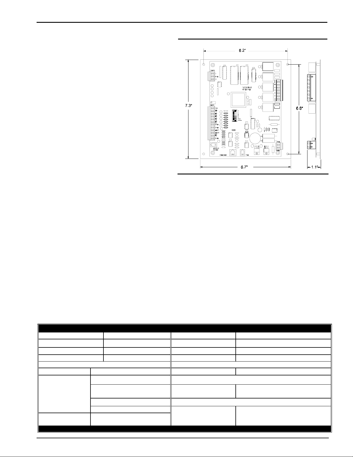
Mounting
The CV-C Controller is provided with an integral backplate for
mounting inside of a control enclosure. An optional factory control
enclosure for the CV-C Controller is available.
Technical Data CV-C Controller
Power 24 Volt AC Weight 1.5 lb.
Power Consumption 12 VA Maximum Network Connection RS-485
Operating Temp
Operating Humidity 90% RH Non-CondensingCommunications RS-485 - 9600 Baud
10°F to 149°F
Inputs: Outputs:
Quantity Available Types Quantity Available Types
Type III-10kohm Sensor
6
1 Modular Phone Jack For
WattMaster reserves the right to change specifications without notice
Form: AZ-CVC-DS-01A-599-0101
Optional Airflow or SP Sensor
0-10 VDC Sensor
0-5 VDC Sensor
4-20mA Sensor
Contact Closure
Binar
Protocol HSI Open Protocol Token Passin
Binary
5 Onboard Relays (2 Amp @ 24 VAC
N.O. Contacts with Suppressors
Analog
2 0-10 Volt DC Out
One Year Warranty
Page
1 of 1
Page 4
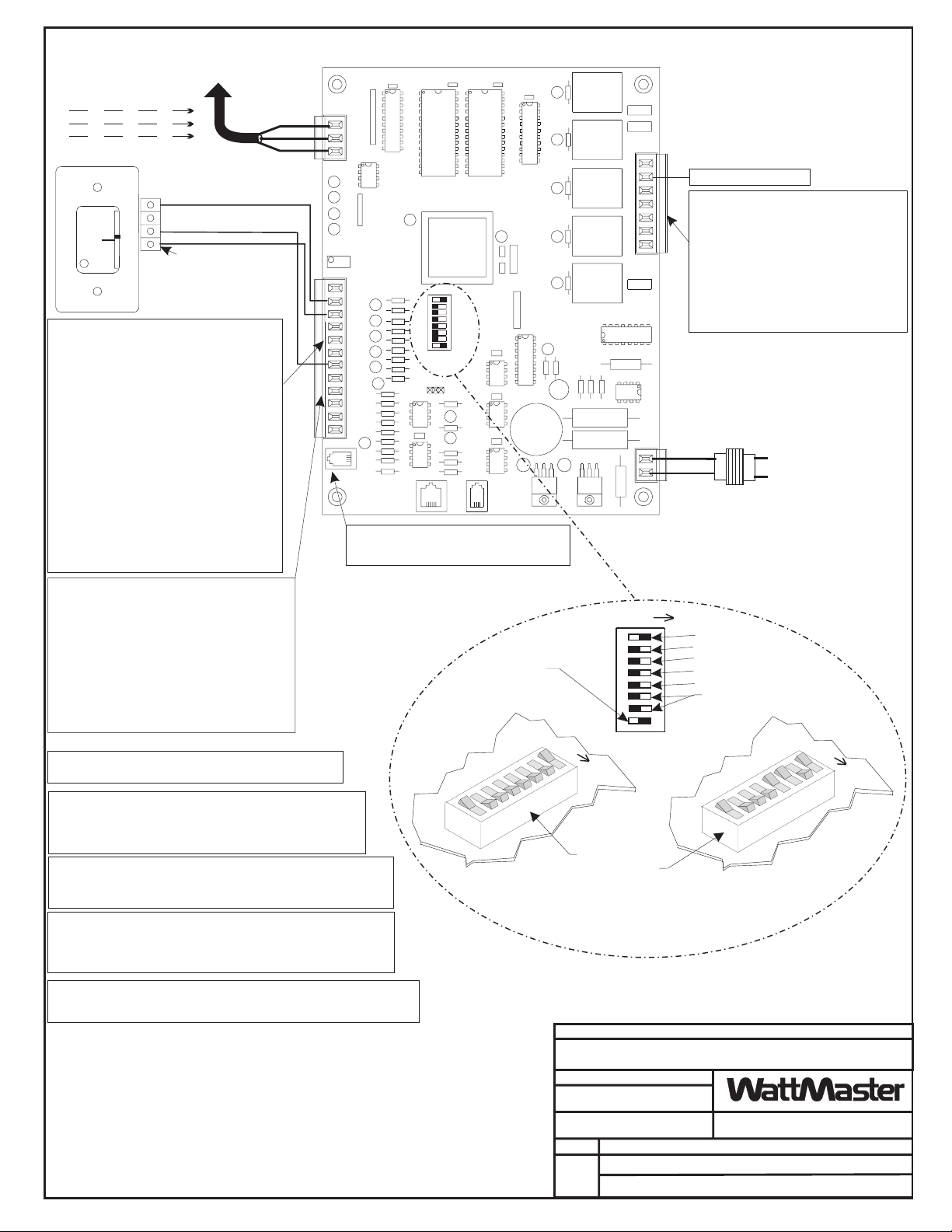
Connect To Next Controller And/Or
All Comm Loop Wiring Is
Straight Thru
T
T
SH
SH
R
SH
R
Room Sensor
W
A
R
M
E
R
NORMAL
C
O
O
OVR
L
E
R
AIN2 Thru AIN5 & AIN7 May Be User
Configured For The Following:
0 - Not Used ( Nothing connected to this input)
1 - Slide Offset
(Requires Flush Mount Wall Sensor)
2 - Supply Air Temperature
3 - Return Air Temperature
4 - Mixed Air Temperature
5 - Outdoor Air Temperature
(Will broadcast to ALL other controllers)
6 - Humidity Sensor (4-20 mA scaling)
7 - Humidity Sensor (0-5 VDC scaling)
8 - CO² Sensor (4-20 mA scaling)
9 - CO² Sensor (0-5 VDC scaling)
10 - Relief Pressure Sensor
(Requires 0-5 VDC ±0.3" WG Sensor)
11 - Dirty Filter Contact (Normally Open)
12 - Alarm Contact (Normally Open)
13 - Alarm Contact (Normally Closed)
14 - Fan Status Contact (Normally Open)
MiniLink On Local Loop
T
T
SH
R
R
TMP
GND
AUX
Connection To
AUX Terminal is Reqd
Only When Sensor
Is Specified With
Slide Adjust Option
Local Loop RS-485
9600 Baud
(See Note 3).
CV- C Controller
COMM
T
SHLD
R
TUC5R PLUS
YS101718
INPUTS
12V
AIN
1
AIN
2
AIN
3
AIN
4
AIN
5
GND
GND
AOUT1
AOUT2
AIN
7
GND
PRESSURE
SENSOR
EXPANSION
AIN6 (Phone Jack) Can Only Be Configured
For An Airflow Sensor And Is Used For
Status or To Verify Fan Operation Only
1
2
4
8
16
32
TOKEN
NETWORK
T'STAT
1-3
M
O
C
R1
R2
R3
R4
R5
4-5
M
O
C
GND
24VAC
R - Fan ON/OFF Only
Relay Outputs R2 Thru R5 May Be User
Configured For The Following:
0 - Not Used (Nothing connected to this
output )
1 - Heating Stage
2 - Cooling Stage
3 - Humidifier Enable
4 - De-Humidifier Enable
5 - Scheduled Relay from Internal Schedule
6 - Scheduled Relay from External Schedule
(Only 1 Available!)
Required VA For Transformer
Each CV-C Controller = 20VA Max.
GND
24VAC
See Note 1
Line Voltage
AOUT1 & AOUT2 May Be User Configured For
The Following:
0 - Not Used (Nothing connected to this output)
1 - Economizer
(Requires Supply or Mixed Air Sensor
2 - Relief Fan VFD Signal
(Requires Relief Pressure Sensor)
3 - Chilled Water Valve
(Requires Supply Sensor)
4 - Hot Water Valve (Requires Supply Sensor)
5 - Humidification / De-Humidification
(Requires Humidity Sensor)
Note: All Temperature Sensors Must Be Thermistor Type III
Which Provide 10K Ohms Resistance @77 Deg. F
Caution!
CV-C Controllers Must Have Address Switches Set Between 1
And 30 When Used With CV or CV-EX Systems. Auto-Zone
Plus Systems Require That The Address Switches Be Set
Between 18 And 30.
Note:
The Power To The CV-C Controller Must Be Removed And
Reconnected After Changing The Address Switch Settings In Order
For Any Changes To Take Effect.
Caution:
Disconnect All Communication Loop Wiring From The CV-C Controller
Before Removing Power From The CV-C Controller. Reconnect Power
And Then Reconnect Communication Loop Wiring.
Note:
Set-up, Programming And Monitoring Of The CV-C Controller Requires The
Use Of A Personal Computer And ZoneView AZ Software.
Notes:
1.)24 VAC Must Be Connected So
That All Ground Wires Remain
Common.
2.)All Wiring To Be In Accordance
3.)AllCommunication Wiring To Be
2 Conductor Twisted Pair With
Shield. Use Belden #82760 Or
Equivalent.
With Local And National Electrical
Codes And Specifications.
This Switch Must Be
In The ON Position
As Shown
ADDRESS
Address Switch Shown Is
Set For Address 1
Must Be Unique To The Other Controllers
ADDRESS ADD
ADD
Controller
Address Switch
Address Switch Shown Is
The Address For Each Controller
On The Local Loop
FILENAME
CVCWIR1.CDR
DATE:
07/08/99
PAGE
1
DESCRIPTION:
CV-C Controller Wiring
1
2
4
8
16
These Switches Should Be
In The OFF Position
As Shown
ADDRESS
Set For Address 13
JOB NAME
CONTROLS
DRAWN BY:
B. CREWS
OE747
ADD
Page 5
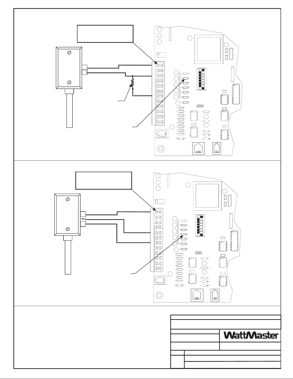
4-20ma
Sensor
Note: Terminal that is Labeled
“12V” on the Terminal Block
has been Electrically Modified
and is Actually 24 Volts
+
-
250 ohm Resistor
Installed Between the
AIN2 Input Terminal
and the GND Terminal
Resistor Must be of 1%
Accuracy or Better
The Pull-up Resistor (PU2),
for the Associated In
Must be Removed When a
4-20ma Sensor is Used
put (AIN2),
4-20ma Sensor Installation
INPUTS
12V
AIN
1
AIN
2
AIN
3
AIN
4
AIN
5
GND
GND
AOUT1
AOUT2
AIN
7
GND
PRESSURE
SENSOR
PU1
PU2
PU3
PU4
PU5
PU7
1
2
4
8
16
32
TOKEN
NETWORK
CV- C Controller
0-5VDC
Sensor
Note: Terminal that is Labeled
“12V” on the Terminal Block
has been Electrically Modified
and is Actually 24 Volts
+
-
The Pull-up Resistor (PU4),
for the Associated In
Must be Removed When a
0-5 VDC Sensor is Used
put (AIN4),
EXPANSION
0-5VDC Sensor Installation
INPUTS
12V
AIN
1
AIN
2
AIN
3
AIN
4
AIN
5
GND
GND
AOUT1
AOUT2
AIN
7
GND
PRESSURE
SENSOR
PU1
PU2
PU3
PU4
PU5
PU7
1
2
4
8
16
32
TOKEN
NETWORK
T'STAT
CV- C Controller
Notes:
1.)24 VAC Must Be Connected So
That All Ground Wires Remain
Common.
2.)All Wiring To Be In Accordance
With Local And National Electrical
Codes And Specifications.
EXPANSION
FILENAME
CVCHUMID1.CDR
DATE:
06/01/00
PAGE
1
CV-C Humidity Sensor Wiring
T'STAT
JOB NAME
CONTROLS
DRAWN BY:
DESCRIPTION:
Auto-Zone
B. CREWS
Page 6
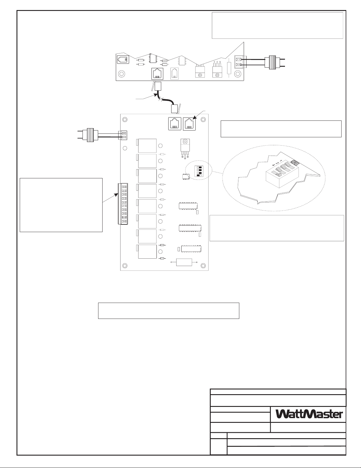
Warning:
If One Transformer Is Used To Power The CV-C Controller And The
Relay Expansion Board, Polarity Must Be Strictly Observed. If The
Polarity Is Reversed, Serious Damage To Both Boards Will Result.
Line Voltage
Required VA For Transformer
Relay Expansion Board = 20VA Max.
See Note 1
Relay Outputs R6 Thru R13 May Be User
Configured For The Following:
0 - Not Used (Nothing connected to this
output )
1 - Heating Stage
2 - Cooling Stage
3 - Humidifier Enable
4 - De-Humidifier Enable
5 - Scheduled Relay from Internal Schedule
6 - Scheduled Relay from External Schedule
(Only 1 Available!)
PRESSURE
SENSOR
EXPANSION
Connect Expansion Board
to CV-C Controller
with Modular Cable
24VAC
GND
24VAC
COM
POWER
N.O. CONTACTS
1-8
RELAY COMMONS 9,10
CV- C Controller
RELAY 1
RELAY 2
RELAY 3
RELAY 4
RELAY 5
RELAY 6
RELAY 7
RELAY 8
T'STAT
IN OUT
EXPANSION PORT
U1
Required VA For Transformer
Each CV-C Controller = 20VA Max.
GND
GND
Line Voltage
24VAC
24VAC
See Note 1
Not Used
Caution!
Relay Expansion Board Must Have Address Switches Set As
Shown Or The Board Will Not Function.
ADDRESS
U3
Caution:
Disconnect The Modular Cable Between The CV-C Controller And The
U4
Relay Expansion Board Before Removing Power From The Relay
Expansion Board. Reconnect Power And Then Reconnect The Modular
Cable Between The CV-C Controller And The Relay Expansion Board.
U5
Notes:
1.)24 VAC Must Be Connected So
That All Ground Wires Remain
Common.
2.)All Wiring To Be In Accordance
With Local And National Electrical
Codes And Specifications.
Relay Expansion Board
Note:
Set-up, Programming And Monitoring Of The CV-C Controller Requires The
Use Of A Personal Computer And ZoneView AZ Software.
FILENAME
CVCWIR1.CDR
DATE:
PAGE
1
JOB NAME
CONTROLS
07/08/99
DRAWN BY:
B. CREWS
DESCRIPTION:
OE351
CV-C Relay Expansion Board Wiring
Page 7
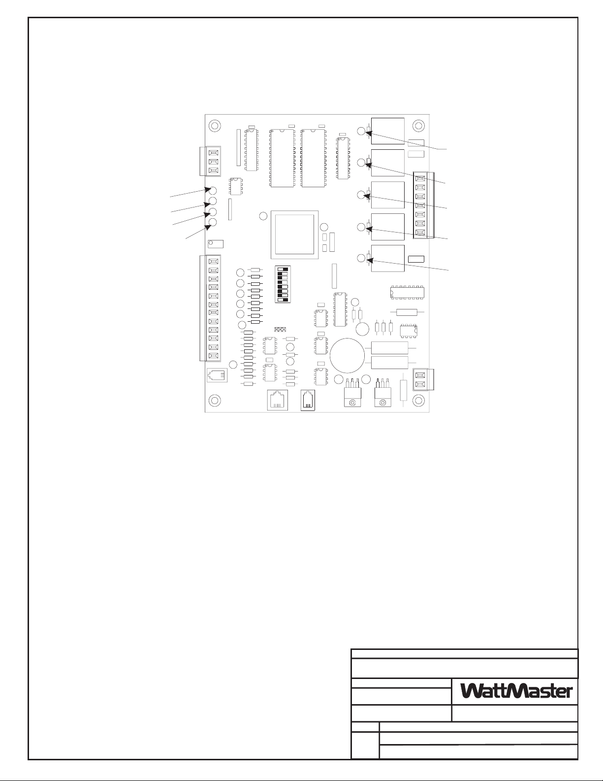
CV-C Controller LED Descriptions
COMMUNICATIONS - LED
POWER - LED
NOT USED
DIAGNOSTIC BLINK CODE - LED
The CV-C Controller uses an on board LED to indicate various diagnostic conditions
during powerup and operation. The CV-C Controller LED is labeled ""COM". Starting
with power up the LED blink codes are as follows:
COMM
INPUTS
T
SHLD
R
12V
AIN
1
AIN
2
AIN
3
AIN
4
AIN
5
GND
GND
AOUT1
AOUT2
AIN
7
GND
PRESSURE
SENSOR
EXPANSION
TUC5R PLUS
YS101718
1
2
4
8
16
32
TOKEN
NETWORK
T'STAT
RELAY #1 ENERGIZED - LED
1-3
M
CO
R1
R2
R3
R4
R5
4-5
M
CO
RELAY #2 ENERGIZED - LED
RELAY #3 ENERGIZED - LED
RELAY #4 ENERGIZED - LED
RELAY #5 ENERGIZED - LED
GND
24VAC
Off for five seconds
SCAN LED blinks the board address (Address 14 = 14 blinks)
Five second pause
Twenty second time delay - LED blinks twenty times
Status code is repeatedly blinked every ten seconds to indicate controller status:
Priority No. of Blinks Status
Lowest 1 Normal Operation
- 2 Override Active
- 3 Bad Zone or Airflow Sensor
- 4 (Not used on CV Units)
Highest 5 Communication Failure
Only the highest priority failure code will be shown. You must correct the highest priority
alarm before other problems will be indicated.
JOB NAME
FILENAME
CVCLED1A.CDR
DATE:
06/01/00
PAGE
DESCRIPTION:
CONTROLS
DRAWN BY:
Auto-Zone
1
LED Descriptions
B. CREWS
Page 8

Page 9

Section 2
Table of Contents
Initialization ................................................................................................................. 1
Operating Summary.................................................................................................... 1
Comm LED Diagnostic Blinks ...................................................................................3
Analog Inputs............................................................................................................... 4
Analog Outputs............................................................................................................5
Relay Outputs ..............................................................................................................5
Pushbutton Override Operation ................................................................................6
HVAC Mode of Operation.......................................................................................... 6
Occupied/Unoccupied Mode of Operation ...............................................................8
Daylight Savings Adjustments ................................................................................... 8
Off Mode of Operation................................................................................................ 9
Vent Mode Operation ................................................................................................. 9
Fan Only Mode Operation ......................................................................................... 9
DX Cooling Operation .............................................................................................. 10
Chilled Water Valve Operation ............................................................................... 13
Step Heating Operation ............................................................................................15
Hot Water Valve Operation ..................................................................................... 18
Fan Control ................................................................................................................ 19
Humidity Control ......................................................................................................20
Humidification ( Relay Enable ).....................................................................................................20
Humidification ( Analog Control ).................................................................................................20
De-Humidification ( Relay Enable )...............................................................................................20
Relief Pressure Control............................................................................................. 21
Economizer Control ..................................................................................................21
Indoor Air Quality..................................................................................................... 23
Scheduled Relays .......................................................................................................23
Fan Status................................................................................................................... 24
Alarm Contact ........................................................................................................... 24
Slide Offset Option .................................................................................................... 24
Dirty Filter Contact ...................................................................................................24
Static Pressure Sensor............................................................................................... 25
Alarm Detection & Reporting .................................................................................. 26
PID Operation............................................................................................................ 28
Page 10

Page 11

Auto-Zone CV-C
Initialization
Initialization
InitializationInitialization
On system powerup LED1 and LED2 are extinguished. After 5 seconds LED2 will blink
out the address of the controller ( Address Switch Setting ). Following this, the LED2
LED will extinguish for another 5 seconds and then begin to blink for a 20 second startup
delay. At the conclusion of this 20 second period, the LED2 LED will begin blinking a
diagnostic code every 10 seconds. This code is described later in this document. The
duration of a powerup initialization sequence is roughly 1 minute plus the user defined
Staggered Start delay described later in this document.
During this initialization period, the controller retrieves all operating setpoints from its
non-volatile EEPROM memory and initializes all outputs to an off condition.
NOTE: All future references to the Constant Volume
Configurable unit in this document use CVC as the
designation.
Section 2
Operating Summary
Operating Summary
Operating SummaryOperating Summary
At all times, after the conclusion of the initialization sequence, the CVC performs a
specific set of operating instructions in the following order: ( a - g Repeat Continuously )
a. Read Analog Inputs for Temperatures, Overrides and Lockout or Reset contact
closures.
b. Check the RS-485 communications port for any new setpoints from the System
Manager and keeps the status updated for the System Manager.
c. If the push-button override is active, it checks the timer to see if the override is
finished.
d. Calculates the current occupied/unoccupied mode from its internal week
scheduling.
e. Calculates what state the output relays and analog output should be set to.
Sequence of Operation 2-1
Page 12

Section 2
f. Updates the diagnostic LED2 blinking.
g. Stores data in the internal trend log if ready for another log.
Auto-Zone CV-C
2-2 Sequence of Operation
Page 13

Auto-Zone CV-C
Comm LED Diagnostic
Comm LED Diagnostic
Comm LED DiagnosticComm LED Diagnostic
Blinks
Blinks
BlinksBlinks
As mentioned earlier, the COMM LED will blink a diagnostic code every 10 seconds
during normal operations. If this LED is off continuously or on continuously, there is a
total failure in the controller and it should be replaced. The diagnostic blinks are
described below in order of priority. The highest priority condition must be corrected
before any lower conditions can be observed and corrected. 1 Blink is the lowest priority
and 5 blinks is the highest priority.
1 Blink Normal operations. No alarm conditions
2 Blinks Pushbutton Override is active during Unoccupied Hours.
3 Blinks Zone Temperature Sensor failure detected.
4 Blinks Not Used in this Controller
5 Blinks RS-485 communications lost
Section 2
Sequence of Operation 2-3
Page 14

Section 2
Analog Inputs
Analog Inputs
Analog InputsAnalog Inputs
Only Analog Input #1 (AIN1) and Analog Input #6 (Airflow Sensor) have a specific
function that cannot be changed. All other inputs are user configurable in one of the
following modes:
0 Not Used ( Nothing connected to this input )
1 Slide Offset ( Requires Flush Mount Wall Sensor with this Option )
2 Supply Air Temperature
3 Return Air Temperature
4 Mixed Air Temperature
5 Outdoor Air Temperature ( Will broadcast to ALL other controllers )
6 Humidity Sensor ( 4-20 ma scaling )
7 Humidity Sensor ( 0-5 vdc scaling )
8 CO² Sensor ( 4-20 ma scaling )
9 CO² Sensor ( 0-5 vdc scaling )
10 Relief Pressure Sensor ( Requires 0-5 vdc ±0.3” WG Sensor )
11 Dirty Filter Contact ( Normally Open )
12 Alarm Contact ( Normally Open )
13 Alarm Contact ( Normally Closed )
14 Fan Status Contact ( Normally Open )
Auto-Zone CV-C
Later in this manual, when it discusses the available options, it will be assumed that you
have installed and configured the correct sensors required for the options you select. If
you haven’t then improper operation will occur.
NOTE: All temperature sensors must be Thermister Type III
which provide 77°F @ 10K Ohms Resistance.
There are a total of 5 programmable Analog Inputs ( AIN2 - AIN5 and AIN7 ).
Analog Input #1 is always configured for a Space Temperature Sensor. This is also the
input that a push-button override would be connected to since the button press
temporarily shorts the thermister sensor to ground to indicate the override request.
Analog Input #6 ( Airflow Sensor ) can be used for status only or to verify fan operation.
No other control outputs can utilize this sensor.
2-4 Sequence of Operation
Page 15

Auto-Zone CV-C
Analog Outputs
Analog Outputs
Analog OutputsAnalog Outputs
There are two Analog Outputs available on this controller. They are both user
configurable as follows:
0 Not Used ( Nothing connected to this output )
1 Economizer ( Requires either Supply Air or Mixed Air Sensor )
2 Relief Fan VFD Signal ( Requires Relief Pressure Sensor )
3 Chilled Water Valve ( Requires Supply Sensor )
4 Hot Water Valve ( Requires Supply Sensor )
5 Humidification / De-Humidification ( Requires Humidity Sensor )
Relay Outputs
Relay Outputs
Relay OutputsRelay Outputs
Section 2
Only Relay Output #1 (R1) has a specific function that cannot be changed. All other
outputs are user configurable in one of the following modes:
0 Not Used ( Nothing connected to this input )
1 Heating Stage
2 Cooling Stage
3 Humidifier Enable
4 De-Humidifier Enable
5 Scheduled Relay from Internal Schedule
6 Scheduled Relay from External Schedule ( Only 1 Available! )
There are a total of 12 additional relays that can be configured. Four are found on the
controller itself (R2 - R5) and the remaining eight are found on an optional relay
expansion board that is connected to the PJ2 Expansion input.
Relay Output #1 is always configured to control the Fan On/Off command.
Sequence of Operation 2-5
Page 16

Section 2
Pushbutton Override
Pushbutton Override
Pushbutton OverridePushbutton Override
Operation
Operation
OperationOperation
This function requires a Space Temperature Sensor that also includes a Push-Button.
During unoccupied hours, the user can force the controller back to occupied operation by
pressing the override button for a period of time between 200 milliseconds and 3 seconds.
This overrides the schedule back to the occupied mode for a user defined period of time.
During Override operations, the user can cancel the override by pressing the override
button for a period of time between 3 seconds and 10 seconds. This removes the override
from the schedule and allows the controller to return to normal unoccupied operations.
If the override button is held for more than 10 seconds, it causes a space sensor failure
alarm. This is due to the fact that the override button actually shorts the space
temperature sensor input to ground. If this input is shorted to ground or left "floating"
with no sensor detected for more than 10 seconds, it is considered a failure.
Auto-Zone CV-C
HVAC Mode of Operation
HVAC Mode of Operation
HVAC Mode of OperationHVAC Mode of Operation
There are five possible modes of operation. These are Cooling Mode, Heating Mode,
Vent Mode, Fan Only Mode and the Off Mode. The HVAC mode of operation is
calculated the same way in both occupied and unoccupied modes of operation.
Off Mode The schedule is off and no overrides are active. There is no heating or
cooling demand in the space. Under these conditions, all outputs will be
off and the analog output will be set to 0.0 vdc.
Vent Mode No heating or cooling demand exists during the occupied mode of
operation. The fan will be on if the CVC is programmed for Constant Fan
operation.
Cool Mode A cooling demand is generated when the space temperature rises half the
amount of the Deadband Setpoint above the currently active Cooling
Setpoint. The space is considered satisfied when it drops that amount
below the Cooling Setpoint.
2-6 Sequence of Operation
Page 17

Auto-Zone CV-C
Heat Mode A heating demand is generated when the space temperature drops half the
amount of the Deadband Setpoint below the currently active Heating
Setpoint. The space is considered satisfied when it rises that amount above
the Heating Setpoint.
Section 2
Fan Only Mode A Fan Only mode cause ALL outputs except for the fan to their inactive
state. It is exactly like the Off Mode except the fan is running. This mode
can be used to temporarily purge the space, etc.
Sequence of Operation 2-7
Page 18

Section 2
Occupied/Unoccupied
Occupied/Unoccupied
Occupied/UnoccupiedOccupied/Unoccupied
Mode of Operation
Mode of Operation
Mode of OperationMode of Operation
Since the CVC contains its own built in Real Time Clock, it can operate from its own
internal scheduling system. This schedule supports a two Start & Stop event per day and
up to 14 Start/Stop Day Holidays. The Holidays all use the same special Holiday
Start/Stop times programmed by the user.
If the current operating mode is unoccupied, the CVC can accept a push-button override
back to the occupied mode. Push-button overrides are not recognized if the current mode
is already occupied. The push-button override duration is user programmed. If the user
wants to extend the current override without reprogramming the Duration, they can reinitialize the existing programmed period by pressing the override button anytime during
the current override. If the current override had been active for 1 hour and 45 minutes and
the user presses the push-button again, the override will reset for another 2 hour period (if
they programmed a 2 hour period), bringing the total override time to 3 hours and 45
minutes. If the user wants to cancel an override before it can time-out, simply hold the
push-button for a period of time between 3 and 10 seconds.
Auto-Zone CV-C
The CVC calculates its current heating and cooling setpoints based on the current mode
of operation. If the command is for unoccupied mode, the CVC adds the unoccupied
setbacks to the occupied heating and cooling setpoints.
Daylight Savings
Daylight Savings
Daylight SavingsDaylight Savings
Adjustments
Adjustments
AdjustmentsAdjustments
Since the CVC system usually contains a System Manager for keypad access to the Status
and Setpoints, the CVC controllers receive a Time Clock broadcast from the System
Manager which keeps all the CVC units synchronized. The System Manager also has the
ability to automatically adjust the time to take the Daylight Savings changes into account.
This is enabled at the System Manager so the effect is automatic at the CVC units. If the
user desires this feature, see Section 3 Setting the Time & Date.
2-8 Sequence of Operation
Page 19

Auto-Zone CV-C
Off Mode of Operation
Off Mode of Operation
Off Mode of OperationOff Mode of Operation
After the schedule goes unoccupied and both heating and cooling demands go away, the
fan stops running, all Relay Outputs are turned off and Analog Output Voltages go to 0.0
vdc. No outputs are allowed to activate in the Off Mode until a heating or cooling
demand occurs. During occupied hours this would be the Vent Mode.
Vent Mode Operation
Vent Mode Operation
Vent Mode OperationVent Mode Operation
During occupied hours when there is no heating or cooling demand, the CVC reverts to a
Vent Mode of operation. The fan is running and the heating and cooling outputs are held
off.
Section 2
See the section titled HVAC Mode of Operation for a graphical representation of how
the Vent Mode is calculated.
Fan Only Mode Operation
Fan Only Mode Operation
Fan Only Mode OperationFan Only Mode Operation
If the user would like to circulate air around the space without causing the heating or
cooling to activate, they can select the Fan Only mode. In this mode all other control
outputs are turned off. All normal scheduled operation is suspended until the Fan Only
mode is canceled. Fan Only mode can be set or cleared from the System Manager or
from the ZoneView front end program on systems equipped for remote communications.
Sequence of Operation 2-9
Page 20

Section 2
DX Cooling Operation
DX Cooling Operation
DX Cooling OperationDX Cooling Operation
If the user has configured the CVC with the DX Cooling option, the following sequence
of operation occurs during a cooling demand.
Once a cooling demand exists (see HVAC Mode of Operation), the following conditions
must be met before any relays can be activated:
a. Make sure any stages of heating are staged off or the hot water valve is
closed.
b. Make sure the Changeover Delay is satisfied. This only applies if the
previous demand was for heating.
c. Check the Outdoor Air Temperature to verify the cooling is enabled to run
due to warm temperatures.
Auto-Zone CV-C
d. If the Economizer option was enabled, the Economizer must be 100%
open if the outside air has enabled it for operation.
e. Check the current Minimum Off Timer to make sure this stage has been
off long enough since the last time it was cycled on and back off.
f. If there is more than 1 stage, check the Staging Delay Time from the
previous stage to be sure it has elapsed before activating the second stage.
g. If we are activating stage #2 or higher, make sure the Space Temperature
Demand is large enough to require the additional stages to activate.
The formula for determining the amount of demand required for each
additional stage is shown below:
Level = ((Deadband / 2) + ((Deadband / 2) * ActiveStages ))
IF Temperature > (Setpoint + Level) THEN its OK to activate another
stage.
( Active Stages refers to the number of compressors currently running. )
Example:
Stage #1 Activates @ 74.5°F - Deactivates @ 73.5°F
Stage #2 Activates @ 75.0°F - Deactivates @ 74.0°F
Stage #3 Activates @ 75.5°F - Deactivates @ 74.5°F
Deadband = 1°F
Setpoint = 74°F
2-10 Sequence of Operation
Page 21

Auto-Zone CV-C
If you have configured the system to control De-Humidification with the DX Cooling
then the compressors are staged on at a rate equal to the Cool Staging Period if the
Humidity reading is above a user defined Humidity Setpoint. This control ignores the
Space Temperature which means it can cause a heating demand in the space. If this
occurs, the cooling remains on to de-humidify the air while the heat runs to warm up the
space. As the humidity drops below the Humidity Setpoint by the Humidity Deadband
value, the compressors can stage off if they have been on at least one minute. If there is
still a cooling demand in the space and the demand requires the currently active cooling
stages to be on, then no staging off will occur until the demand drops low enough to stage
the compressors off.
Ignoring the Humidity Control for the moment, the compressors will stage off if the
following conditions are true.
a. The space temperature has dropped enough to remove a demand for the
currently active stage. ( see previous screen for stage off levels )
b. The outside air has dropped enough to disable the compressors.
Section 2
c. The Supply Air has dropped below 45°F or 7.2°C.
d. Someone has reduced the number of cooling stages to less than what are
currently active.
e. The compressor stage has been on at least one minute.
The staging of compressors always occurs based on both temperature demand and
specific intervals based on whether the unit is staging up or down. There are four timers
that need to be satisfied:
Staging Delay Timer ( User Adjustable )
a.
If a large demand exists when the cooling mode is entered all available
stages would be called for. Only one stage at a time can actually be
activated. The Staging Delay period must be satisfied before each additional
stage is activated.
Minimum Run Timer ( Not Adjustable )
b.
Once a stage has been activated, it must remain for at least one minute
before it is allowed to turn off again. This protects the equipment from short
cycling.
Sequence of Operation 2-11
Page 22

Section 2
Auto-Zone CV-C
c.
d.
The Relay Output assignment always assigns cooling stages starting with those defined
on the TUC-5R+ board and then any additional stages defined on the Relay Expansion
board. The stages are assigned from the lowest relay number up to the highest. If you
defined 6 relays for cooling and two were on the TUC-5R+ board and the remaining four
were on the relay expansion board, then stage #1 would be the lower relay number on the
TUC board and stage #3 would be the lowest relay number on the expansion board.
NOTE: You must take into account the stage assignments
Minimum Off Timer ( User Adjustable )
Once a stage has been turned off, it must remain off for this amount of
time before it can be restarted.
Changeover Delay ( User Adjustable )
If the previous HVAC mode was for heating, the cooling mode is not
allowed to activate any compressors until this delay period has been
satisfied. This period is used to prevent rapid cycling back and forth
between the heating and cooling modes.
when you physically wire the controller and/or
expansion board into your AHU equipment.
2-12 Sequence of Operation
Page 23

Auto-Zone CV-C
Chilled Water Valve
Chilled Water Valve
Chilled Water ValveChilled Water Valve
Operation
Operation
OperationOperation
If the user has configured the CVC with the Chilled Water Valve option, the following
sequence of operation occurs during a cooling demand.
Once a cooling demand exists (see HVAC Mode of Operation), the following conditions
must be met before the valve modulation signal is activated.
a. Make sure any stages of heating are staged off or the hot water valve is
closed.
b. Make sure the Changeover Delay is satisfied. This only applies if the
previous demand was for heating.
Section 2
c. Check the Outdoor Air Temperature to verify the cooling is enabled to run
due to warm temperatures.
d. If the Economizer option was enabled, the Economizer must be 100%
open if the outside air has enabled it for operation.
If you have configured the system to control De-Humidification with the Chilled Water
Valve then the valve will modulate open at a user defined rate if the Humidity reading is
above a user defined Humidity Setpoint. This control ignores the Space Temperature
which means it can cause a heating demand in the space. If this occurs, the cooling
remains on to de-humidify the air while the heat runs to warm up the space. As the
humidity drops below the Humidity Setpoint by the Humidity Deadband value, the valve
can modulate closed. If there is still a cooling demand in the space then the valve will still
modulate to maintain a user defined supply air temperature.
Ignoring the Humidity Control for the moment, the chilled water valve operates as
follows:
a. A cooling demand equal to the Cooling Setpoint plus half the Deadband has
occurred in the space.
b. If the cooling mode is enabled by outside air, then the valve modulates to
maintain a supply temperature, defined by the user, until the demand drops
Sequence of Operation 2-13
Page 24

Section 2
below the cooling setpoint by the same amount it rose above it to start the
demand.
c. Once the cooling demand has been satisfied, the valve will go fully closed
until the next cooling demand or until the Humidity requires the valve to
open.
Once the Chilled Water Valve is enabled for operation, the actual valve position is
calculated using a Proportional, Integral and Derivative (PID) formula. All three formula
constants are user adjustable along with a fourth setpoint for the Integrating Interval.
There are defaults programmed in the code that should not be changed unless the user,
through actual observation, has determined that the valve is hunting or is not operating
quickly enough to maintain a constant Supply Air Temperature.
A later section entitled PID Operation can be refereed to for an actual example of code
that does the valve positioning. This formula applies to both Chilled Water and Hot
Water Valve operations.
Auto-Zone CV-C
2-14 Sequence of Operation
Page 25

Auto-Zone CV-C
Step Heating Operation
Step Heating Operation
Step Heating OperationStep Heating Operation
If the user has configured the CVC with the Step Heating option, the following sequence
of operation occurs during a heating demand.
If the controller was configured for De-Humidification, then any statements concerning
the cooling being off before the heat can activate can be ignored as the cooling is used in
conjunction with the heat to reduce humidity and maintain space temperature.
Once a heating demand exists (see HVAC Mode of Operation), the following conditions
must be met before any relays can be activated:
a. Make sure any stages of cooling are staged off or the chilled water valve is
closed.
b. Make sure the Changeover Delay is satisfied. This only applies if the
previous demand was for cooling.
Section 2
c. Check the Outdoor Air Temperature to verify the heating is enabled to run
due to cool temperatures.
d. If you have Economizer control, the Economizer must be at its minimum
ventilation position.
e. Check the current Minimum Off Timer to make sure this stage has been
off long enough since the last time it was cycled on and back off.
f. If there is more than 1 stage, check the Staging Delay Time from the
previous stage to be sure it has elapsed before activating the second stage.
g. If we are activating stage #2 or higher, make sure the Space Temperature
Demand is large enough to require the additional stages to activate.
The formula for determining the amount of demand required for each
additional stage is shown below:
Level = ((Deadband / 2) + ((Deadband / 2) * ActiveStages ))
IF Temperature < (Setpoint - Level) THEN its OK to activate another
stage.
( Active Stages refers to the number of heating stages currently running. )
Sequence of Operation 2-15
Page 26

Section 2
Auto-Zone CV-C
Example:
Stage #1 Activates @ 71.5°F - Deactivates @ 72.5°F
Stage #2 Activates @ 71.0°F - Deactivates @ 72.0°F
Stage #3 Activates @ 70.5°F - Deactivates @ 71.5°F
Heating can stage off if the following conditions are true.
a. The space temperature has risen enough to remove a demand for the
currently active stage. ( see previous screen for stage off levels )
b. The outside air has risen enough to disable the heating.
c. The Supply Air has risen above 150°F or 65.5°C.
d. Someone has reduced the number of heating stages to less than what are
currently active.
e. The heating stage has been on at least one minute.
Deadband = 1°F
Setpoint = 72°F
The heat staging always occurs based on both temperature demand and specific intervals
based on whether the unit is staging up or down. There are four timers that need to be
satisfied:
Staging Delay Timer ( User Adjustable )
a.
If a large demand exists when the heating mode is entered all available
stages would be called for. Only one stage at a time can actually be
activated. The Staging Delay period must be satisfied before each additional
stage is activated.
b. M
inimum Run Timer ( Not Adjustable )
Once a stage has been activated, it must remain for at least one minute
before it is allowed to turn off again. This protects the equipment from short
cycling.
Minimum Off Timer ( User Adjustable )
c.
2-16 Sequence of Operation
Page 27

Auto-Zone CV-C
Once a stage has been turned off, it must remain off for this amount of time
before it can be restarted.
Changeover Delay ( User Adjustable )
d.
If the previous HVAC mode was for cooling, the heating mode is not
allowed to activate any heat stages until this delay period has been satisfied.
This period is used to prevent rapid cycling back and forth between the
heating and cooling modes.
The Relay Output assignment always assigns heating stages starting with those defined
on the TUC-5R+ board and then any additional stages defined on the Relay Expansion
board. The stages are assigned from the lowest relay number up to the highest. If you
defined 6 relays for heating and two were on the TUC-5R+ board and the remaining four
were on the relay expansion board, then stage #1 would be the lower relay number on the
TUC board and stage #3 would be the lowest relay number on the expansion board.
Section 2
NOTE: You must take into account the stage assignments
when you physically wire the controller and/or
expansion board into your AHU equipment.
Sequence of Operation 2-17
Page 28

Section 2
Hot Water Valve
Hot Water Valve
Hot Water ValveHot Water Valve
Operation
Operation
OperationOperation
If the user has configured the CVC with the Hot Water Valve option, the following
sequence of operation occurs during a cooling demand.
If the controller was configured for De-Humidification, then any statements concerning
the cooling being off before the heat can activate can be ignored as the cooling is used in
conjunction with the heat to reduce humidity and maintain space temperature.
Once a heating demand exists (see HVAC Mode of Operation), the following conditions
must be met before the valve modulation signal is activated.
a. Make sure any stages of cooling are staged off or the chilled water valve is
closed.
Auto-Zone CV-C
b. Make sure the Changeover Delay is satisfied. This only applies if the
previous demand was for cooling.
c. Check the Outdoor Air Temperature to verify the cooling is enabled to run
due to warm temperatures.
d. If you have Economizer control, the Economizer must be at its minimum
ventilation position.
Heating can modulate closed if the following conditions are true.
a. A heating demand equal to the Heating Setpoint plus half the Deadband has
occurred in the space.
b. If the heating mode is enabled by outside air, then the valve modulates to
maintain a supply temperature, defined by the user, until the demand rises
above the cooling setpoint by the same amount it rose above it to start the
demand.
c. Once the heating demand has been satisfied, the valve will go fully closed
until the next heating demand.
2-18 Sequence of Operation
Page 29

Auto-Zone CV-C
Once the Hot Water Valve is enabled for operation, the actual valve position is calculated
using a Proportional, Integral and Derivative (PID) formula. All three formula constants
are user adjustable along with a fourth setpoint for the Integrating Interval. There are
defaults programmed in the code that should not be changed unless the user, through
actual observation, has determined that the valve is hunting or is not operating quickly
enough to maintain a constant Supply Air Temperature.
A later section entitled PID Operation can be referred to for an actual example of code
that does the valve positioning. This formula applies to both Chilled Water and Hot
Water Valve operations.
Fan Control
Fan Control
Fan ControlFan Control
The Fan runs continuously in the occupied mode and cycles on and off with the heating
or cooling in the unoccupied mode unless the user configures it for the Fan Cycle Mode.
In this mode, the Fan will start before any other outputs can be activated. It must have
been off for at least one minute before it can be restarted.
Section 2
Once the fan has been commanded to turn off, it first checks to see if all heating and
cooling stages are off or valves are closed. If everything has been off for at least 30
seconds, the fan is allowed to stop.
If the user has entered the Fan Only force mode, this will be the only active output and all
scheduling or anything else that normally affects the fan will be ignored until the Fan
Only mode is removed.
WARNING: The Fan Only mode does not automatically clear itself. The user must
remove this force command or the fan will never turn off and no
heating or cooling will occur!
Sequence of Operation 2-19
Page 30

Section 2
Humidity Control
Humidity Control
Humidity ControlHumidity Control
If you selected the De-Humidification control using DX Cooling or the Chilled Water
Valve, then that operation is discussed in those sections. This section applies to an Output
Relay that has been assigned to humidity control or an Analog Output that is assigned to
control the humidity level. If an external device will be used to increase or decrease the
humidity but it needs an enable signal from the CVC, then this is the mode to select.
Auto-Zone CV-C
Humidification ( Relay Enable )
As the humidity drops below the user adjustable Humidity Setpoint, the assigned Output
Relay activates. It remains active until the Humidity rises above the setpoint by the user
adjustable Humidity Deadband amount. This operation can occur in both the Occupied
and the Unoccupied mode and the fan will be started if it is not already running.
The only mode that will prevent this Humidification control from occurring is the Fan
Only Mode.
Humidification ( Analog Control )
If you assigned an Analog Output for this mode, the output signal voltage will ramp from
the minimum programmed voltage to the maximum programmed voltage ( 0 to 100% ) as
the Humidity drops below the setpoint. When the humidity level drops below the setpoint
by the Humidity Deadband amount, the output will be at its 100% programmed voltage.
Since the CVC is controlling this voltage signal, this mode requires the fan to be running.
If the voltage signal is greater than 0% the fan is verified to be running or it is started.
The only mode that will prevent this Humidification control from occurring is the Fan
Only Mode.
De-Humidification ( Relay Enable )
If you aren’t using mechanical cooling to control the humidity level, then you can assign
an Enable Relay to activate whenever the Humidity rises above the Humidity Setpoint. It
will remain on until the humidity drops below the setpoint by the Humidity Deadband
amount.
The only mode that will prevent this Humidification control from occurring is the Fan
Only Mode.
No Analog Output Control is available for De-Humidification.
2-20 Sequence of Operation
Page 31

Auto-Zone CV-C
Relief Pressure Control
Relief Pressure Control
Relief Pressure ControlRelief Pressure Control
If you have assigned both a Relief Pressure Sensor on an Analog Input and Relief Fan
control on one of the Analog Outputs, then the following control occurs.
If the Fan is running then the relief fan voltage signal increases as the relief pressure rises
above the Relief Pressure Setpoint by 0.02” WG. The voltage decreases as the pressure
drops below the setpoint by 0.02” WG. this 0.04” WG deadband is not user adjustable.
If the pressure ever exceeds the setpoint by 0.10” WG, the voltage signal will be doubled
in an attempt to reduce building pressure before damage occurs.
The relief fan voltage signal remains at zero volts whenever the main fan is off.
Section 2
Economizer Control
Economizer Control
Economizer ControlEconomizer Control
If you assigned an Analog Output to control an Outside Air Damper ( Economizer ) then
the following sequence occurs.
Assuming that the current HVAC mode is calling for Cooling, the economizer is enabled
for operation when the outside air temperature is below the Enable Setpoint or a Wetbulb
Temperature, received from another controller on the communications loop, is receiving
a value that is below the Enable Setpoint. Whichever value that is being used, the
economizer is enabled when the temperature is 1° below the enable setpoint and is
disabled when the temperature rises 1° above the setpoint.
The economizer is always considered to be the first stage of cooling. If it cannot satisfy
the space temperature with the supply air or mixed air temperature it is providing, then
mechanical cooling will be enabled to operate if the outside air is above the mechanical
cooling lockout setpoint.
The user can select either Supply Air Temperature control or Mixed Air Temperature
control. If the user selects Mixed Air Temperature but then neglects to configure an
Analog Input as a Mixed Air sensor, the controller will default to using the Supply Air
Temperature. If no supply air temperature sensor is provided, then incorrect control will
occur!
Once the economizer is enabled to begin controlling, it checks the outside air temperature
and calculates a starting position to immediately drive to instead of just creeping slowly
open from its programmed minimum position. Once this initial adjustment is made, the
Sequence of Operation 2-21
Page 32

Section 2
economizer watches the movement of the controlling temperature to determine if it
should make any further adjustments. If the temperature is dropping but it is still above
setpoint, the economizer will not open any further unless the temperature stops dropping
and becomes stagnant at a level above the setpoint. The same is true if the temperature is
below the setpoint and rising, no adjustments are made unless the temperature stagnates
as some fixed value.
If the economizer is moving too fast or too slow to maintain stable temperature control,
the user can adjust a Control Rate value between a value of 0.1 and 9.9 with 9.9 being the
fastest control and 0.1 being the slowest control.
As mentioned in the DX Cooling and Chilled Water Valve operations, the economizer
must be fully open before mechanical cooling can occur. On the same hand, if mechanical
cooling has been initiated, the economizer must remain fully open until the mechanical
cooling is removed or the supply air temperature drops below 40°F or 4.4°C. If this
occurs, the economizer closes by 5% every 10 seconds until it is fully closed or the
supply air has recovered enough to allow the economizer to be used again. If the supply
air rises above this low limit protection, the economizer will begin to creep open if it
needs to reduce the supply air or mixed air ( not likely ) downward.
Auto-Zone CV-C
One other test that can occur but is not generally required occurs when the user has
installed a return air sensor. If the outside air is within 5° of the return air temperature
then it can’t really be used for cooling the supply air so the economizer is disabled and
maintained at the user defined minimum position.
2-22 Sequence of Operation
Page 33

Auto-Zone CV-C
Indoor Air Quality
Indoor Air Quality
Indoor Air QualityIndoor Air Quality
If you have configured an Analog Input to read a CO² sensor or to receive the broadcast
of CO² from another unit, this CVC can override the minimum economizer position to
bring in more fresh outside air to relieve the condition.
As the CO² level rises above the user adjustable CO² Setpoint, the Minimum Economizer
position switches over to a user adjustable value of up to 100% and makes sure the
economizer does not close any further than this new value. If the value is less than 100%
and the economizer is opening to control supply or mixed air, the economizer is still free
to modulate between 100% and this new minimum position. The only condition that will
override the minimum is supply air dropping below the 40°F or 4.4°C protection limit.
As the CO² level drops below the CO² Setpoint by the user adjustable Deadband value,
the original Economizer Minimum Position is restored and the economizer is now free to
modulate over its entire range again, or return to minimum if cooling is not required.
Section 2
Scheduled Relays
Scheduled Relays
Scheduled RelaysScheduled Relays
If you define one of the Output Relays to follow the Internal Schedule, then whenever the
Schedule is Occupied the relay will activate. Whenever the schedule goes Unoccupied the
relay de-activates. Push-button overrides will not re-activate this relay. Only the
Occupied mode will activate the relay. Only one relay should be assigned to follow an
external schedule.
If you define one of the Output Relays to follow an External Schedule then the same
conditions apply. That relay will follow the broadcast receipt of the selected schedule.
Only one relay should be assigned to follow an external schedule since there is only one
Schedule Setpoint available. If you assigned more than one relay, they would all follow
the same schedule.
The External Schedule can only be received from an Auto-Zone Optimal Start Scheduler
installed on one of the communications loops in your building. These options require the
ZoneView AZ computer program for programming and monitoring.
Sequence of Operation 2-23
Page 34

Section 2
Fan Status
Fan Status
Fan StatusFan Status
You can configure one of the Analog Inputs to monitor a binary contact closure for proof
of airflow. This is currently a Status Only input and will not affect the operations of the
CVC if no proof of flow is detected.
Alarm Contact
Alarm Contact
Alarm ContactAlarm Contact
If you require a generic type alarm indication on a contact closure, you can configure an
Analog Input for either a Normally Open or a Normally Closed contact. This alarm will
not affect the CVC operation but it will be reported at the ZoneView AZ computer screen
and can be used to generate alarm callouts if all the proper equipment is installed for
remote communications.
Auto-Zone CV-C
Slide Offset Option
Slide Offset Option
Slide Offset OptionSlide Offset Option
If you install Flush Mount Wall Sensors with the optional slide adjustment, you can affect
the current heating and cooling setpoints up or down by a programmable amount. This
can be as much as 5°F above or below the current setpoints or as little as 1°F. The
position of the slide is proportional so that if it is halfway up or down, you affect the
setpoints by half the amount you programmed. If the slide is all the way up or down you
create the maximum effect on the setpoints.
Dirty Filter Contact
Dirty Filter Contact
Dirty Filter ContactDirty Filter Contact
You can configure an Analog Input to monitor for a differential pressure contact closure
in the event the filters become clogged. This contact closure can generate an alarm callout
if desired and if the remote communications options have been installed.
2-24 Sequence of Operation
Page 35

Auto-Zone CV-C
Static Pressure Sensor
Static Pressure Sensor
Static Pressure SensorStatic Pressure Sensor
You can install a Static Pressure Sensor on the fixed Analog Input labeled Pressure
Sensor and be provided automatically with the current static pressure. This is a status
only reading that can be used to verify fan operation if you are viewing this system with
the ZoneView AZ computer program. No setup or programming is required. If the input
detects the sensor, you will see the reading.
Section 2
Sequence of Operation 2-25
Page 36

Section 2
Alarm Detection &
Alarm Detection &
Alarm Detection &Alarm Detection &
Reporting
Reporting
ReportingReporting
The CVC continuously performs self diagnostics during normal operations to determine
if any operating failures have occurred. These failures can be reported to the user in
several ways, depending on the options installed by the user. If you are using the
ZoneView AZ computer software to interface with the unit, you can enable or disable
each alarm condition as desired to prevent nuisance alarms from being reported. This
alarm disabling does not apply to the System Manager alarm polling described below, it
is only from remote alarm callout.
The System Manager continuously polls all installed controllers for alarm conditions. If it
detects any alarm, the ALARM LED on the right side of the front panel illuminates and
latches, even though the alarm may have gone away on the controller. This latching
mechanism allows the user to detect intermittent alarm conditions and begin closer
monitoring of the offending controller to determine what caused the alarm condition.
There is keypad access to retrieve the Loop and Board Addresses of the units in alarm.
Auto-Zone CV-C
On Auto-Zone systems equipped with the Remote Communications option (OE361-04-S)
the ZoneView AZ program can display alarm conditions on each Status Screen as the
user scrolls through the controllers on their system. The CommLink II Communications
Interface can also place a call to a Pager number for on the spot notification of alarm
conditions.
Alarm conditions are not latched in the controller generating the alarm. They can come
and go as the condition is corrected. Alarms are latched at the System Manager so a
record of the alarm is not lost.
Possible Alarm Conditions
Bad Space Sensor
If the space sensor is missing or has been shorted out for more than 10
seconds, an alarm is generated.
2-26 Sequence of Operation
Page 37

Auto-Zone CV-C
Cooling Failure
Anytime the first stage of cooling is activated on CV-C units the Supply
Air has 30 minutes to change by 5°F from its starting condition. If this
does not occur an alarm is generated. This test is not performed if your
system is configured for Chilled Water Valve operation.
Heating Failure
The same conditions apply as listed for Cooling Failure except it looks at
the first stage of heating to test the condition. This test is not performed if
your system is configured for Hot Water Valve operation.
Space Temperature Alarm
If the space temperature is above or below its cooling or heating setpoints
by 5°F for at least 30 minutes, an alarm is generated.
Dirty Filter Alarm
If the Dirty Filter contact closes no operational changes are made but an
alarm is generated.
Section 2
Generic Alarm
If the Normally Open or Normally Closed Generic Alarm input becomes
active and alarm is generated.
NOTE: If you do not required alarm reporting at the System
Manager simply disconnect the RS-485 connector from
the System Manager and force it to Rebuild the Alarm
Map. (See Section 3 Rebuilding Alarm Map)
Sequence of Operation 2-27
Page 38

Section 2
PID Operation
PID Operation
PID OperationPID Operation
The Hot & Chilled Water Valves are controlled via a Proportional, Integral, Derivative (
PID ) loop. This method of control provides accurate temperature control with minimal
adjustments to the valve position. The best method of explaining the PID operation is to
show a simplified form of the formulas incorporated into the controller code.
The following abbreviations will be used in the formula:
TimeSP = Integrating Interval
HotSP = Supply Air Temperature Setpoint
Kp = Proportional Constant
Ki = Integral Constant
Kd = Derivative Constant
P = Proportional Error
I = Integral Error
D = Derivative Error
HWValve = Calculated Valve Position
SupplyAir = Current Supply Air Temperature Reading
Auto-Zone CV-C
IF the TIMER has exceeded the TimeSP THEN
Error = HotSP - SupplyAir
P = ( Error x ( Kp / 100 )) x 100
I = ( Error x ( Ki / 10))
D = ( Error - OldError ) x ( Kd / 10 )
HWValve = P + I + D
OldError = Error “ Save current error for next time “
END ROUTINE
The Error is the difference between the Setpoint and the actual Temperature. The P error
uses a limited amount of this error to create a proportional only valve position. For
example, if the Kp was set to 10 then a 10°C temperature error would cause the P error
to set the valve 100% open.
10° Error = ( 10 x ( 10 / 100)) x 100 = 100%
5° Error = ( 5 x ( 10 / 100)) x 100 = 50%
2-28 Sequence of Operation
Page 39

Auto-Zone CV-C
The Integral ( I ) is added to itself each time through the loop. This prevents the valve
from stopping at a point of equilibrium where the proportional error is not changing,
therefore the valve position would be changing. The amount of effect the Integral can
have is limited by the Ki constant.
The Derivative ( D ) is used to track the rate of change in temperature error from
setpoint. If the last change was small, the derivative would have very little affect since the
( Error - OldError ) subtraction would yield a small value. In this case, the derivative
would not affect on the final valve position calculation.
If the last error was large, indicating the temperature was rapidly moving toward or away
from the setpoint, the valve position calculation could make a large adjustment due to the
proportional error. This could have the affect of causing hunting or overshoot in the
temperature control. To limit the proportional effect during rapid temperature changes,
the derivative becomes the brakes of the system if we are approaching setpoint or the
accelerator if we are moving away from the setpoint. If the temperature error had
increased from the last calculation, the derivative would create a positive value that
would be added to the proportional and integral values to create an even greater valve
position:
Section 2
Accelerator Example:
OldError = 2°
Error = 4°
( Error - OldError ) = 2
P + I + 2 = Increased valve position
Brakes Example:
OldError = 2°
Error = 0°
( Error - OldError ) = -2
P + I + ( -2 ) = No Change in valve position
Since the Proportional Error was also reduced the derivative had the effect of canceling
any change in the valve position until it detects another movement down in the
temperature error. If the effect of remaining unchanged causes the temperature error to
increase again, then the valve position would again increase without ever having
experienced an unneeded or undesired decrease.
If the temperature had continued to drop, then the derivative would add to the
proportional error in an attempt to catch the temperature before it went too far below
setpoint.
Sequence of Operation 2-29
Page 40

Section 2
The Integrating Interval ( TimeSP ) controls how many times per minute the calculations
are made. The default number of times per minute is set to 12
( 60 Seconds / 5.0 Seconds = 12 Times Per Minute ). This allows for a rapid reaction to
changes in temperature. If the default Constants and this TimeSP cause unstable
operation, they can be adjusted to bring the valve positioning under control.
NOTE: It is not possible to recommend which variables to change or how much to
change them without firsthand observation of the valve operation.
It is recommended that the default setpoints be used until you can observe actual heating
control and determine if any changes need to be made. Changes made to the PID
Constants should be made in small increments and one at a time. The results should then
be studied before making any further changes.
Auto-Zone CV-C
2-30 Sequence of Operation
Page 41

Page 42

Form: WM-CVC-SQW-01A Printed in the USA March 2002
All rights reserved Copyright 2002
WattMaster Controls Inc. • 8500 NW River Park Drive • Parkville MO • 64152
Phone (816) 505-1100 www.wattmaster.com Fax (816) 505-1101
 Loading...